MI-395 - Support pour écran plat Mount-It! - Free user manual and instructions
Find the device manual for free MI-395 Mount-It! in PDF.


| Product Type | Fireplace TV Mount |
| Brand | Mount-It! |
| Model | MI-395 |
| Weight Capacity | 72.6 lbs (33 kg) |
| VESA Compatibility | Up to 600x400 mm |
| TV Size Compatibility | Up to 70 inches (estimated) |
| Mounting Options | Wood studs or concrete/brick |
| Material | Heavy-duty steel |
| Extension Type | Spring arm with tension adjustment |
| Tilt | Yes, adjustable angle |
| Height Adjustment | Yes, with spring tension |
| Leveling | Post-installation leveling possible |
| Cable Management | Yes, integrated |
| Included Decorative Plates | Yes, to cover wall plate |
| Hardware Included | Mounting bolts, wall anchors, Allen wrench, ratchet wrench |
| Product Weight | Approximately 15 lbs |
| Power Source | None (manual operation) |
| Maintenance | Wipe with dry cloth; check hardware periodically |
| Safety Warnings | Choking hazard; do not exceed weight capacity; do not install on drywall alone |
| Warranty | Contact Mount-It! support |
Frequently Asked Questions - MI-395 Mount-It!
User questions about MI-395 Mount-It!
0 question about this device. Answer the ones you know or ask your own.
Ask a new question about this device
Download the instructions for your Support pour écran plat in PDF format for free! Find your manual MI-395 - Mount-It! and take your electronic device back in hand. On this page are published all the documents necessary for the use of your device. MI-395 by Mount-It!.
USER MANUAL MI-395 Mount-It!
natural_image
Technical line drawing of a mechanical frame assembly (no text or symbols)
Scan this QR code for product information, videos, and assembly assistance.
FIREPLACE TV MOUNT

HAVE QUESTIONS?
Monday - Friday from 8:00am - 4:00pm PST

support@mount-it.com

(855) 925-5668

www.mount-it.com
Thank you for choosing Mount-It!
MAINTENANCE: A intervention sigulants (no moist taxa len taxa more) are
SHERN TERRAINE: A FIM-based regulator (see more info see it as more) verified that the support was a version of one of its best
(1) A structure of a set of different sets of the set of the set of different sets of the set of different sets. The set of different sets is also a set of different sets of the set of different sets of the set of different sets of the set of different sets of the set of different sets of the set of different sets of the set of different sets of the set of different sets of the set of different sets of the set of different sets of the set of different sets of the set of different sets of the set of different sets of the set of different sets of the set of different sets of the set of different sets of the set of different sets of the set of different
WALL MOUNTING HARDWARE

W-A (x6)
\$T6.3×55

W-B (x6)
010x45

W-C (x6)
D6
Check carefully to make sure there are no missing or defective parts. Some hardware provided may not be used. Use the correct wall mounting and TV mounting hardware suitable for your installation.
CHOKING HAZARD. Package includes small parts.
Not for children under 3 years. Adult supervision is required
Missing Parts? Call us at (855) 925-5668 and we will ship replacement parts free of charge.
MOUNT-IT!
Step 1 Step 3
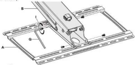
Installing The Spring Arm To The Wallplate
Attach the Spring Arm (B) and Wall Plate (A) with bolts (4 x l) as shown, using the Allen Wrench (Q) to tighten securely.
Step 2
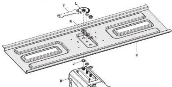
Installing The TV Bracket To The Spring Arm
Placing Washer (J) on the 3 exposed bolts on the Spring Arm (B) attach TV BRACKET (C) as shown then secure with Washer (K) and Nut (L). Use Wrench (T) to tighten securely.
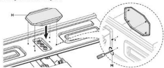
Attaching The Plastic Plate To The TV Bracket
Install Plastic Plate (H) to cover the nuts from the previous step inserting Bolt (M) from the opposite side as shown using a screwdriver to tighten.
Positioning The Mount Over The Fireplace
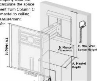
The height of the mount is dependent on the depth of the mantel to ensure the spring arm clears the mantel when fully lowered.
Determine the proper wall placement using the chart below.
Measure the depth of your mantel and locate the closest measurement in column A that your mantel depth is Smaller Than Or Equal To. The corresponding measurement in column B "Mantel Clearance" indicates the minimum required mounting height to properly clear the
Indicates the minimum required mounting height to properly clear the mantel. Use Column C "Min. Wall Space Height" to calculate the space your TV+Mount requires. Ensure that the measurement from Column C is less than your total wall space as measured from mantel to ceiling. Include any attached soundbars in the TV Height measurement.
Note: Installing below the required mounting height for your mantel depth will prevent the mount from fully clearing the mantel.
| A. Mantel Depth | B. Mantel Clearance | C. Mln. Wall Space Height |
| ≤5 inches | 1.2 inches | TV Height + 11.5" |
| ≤9.8 inches | 3 inches | TV Height + 14.5" |
| ≤11.8 inches | 4 inches | TV Height + 15" |
| ≤13.8 inches | 5 inches | TV Height + 16.5" |
Step 4
Option 1. Wood Studs Installation
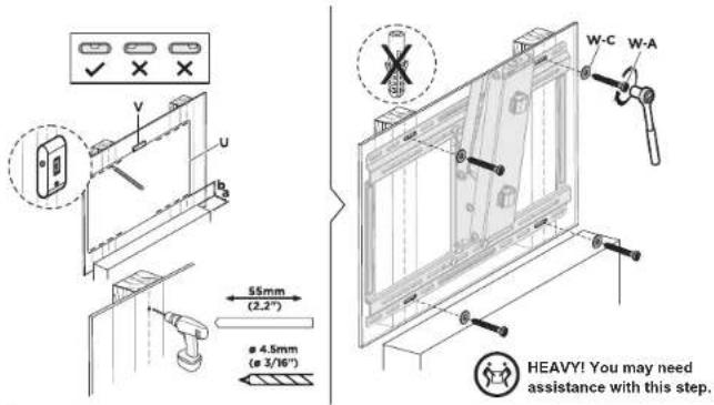
Use a stud finder to locate 2 drywall studs and mark the location with a pencil. Using a bubble level to ensure straightness, hold the Wall Template (U) to the wall at required mounting height determined by step 3. Mark the center of the template holes which align with the center of each stud.
Use a 3/16" (4.5mm) drill bit to drill pilot holes on the wall with a depth of 2.2" (55mm). Please note, failure to drill pilot holes may result in the lag bolt heads snapping during installation.
Holding the mount to the wall aligned with the pilot holes install Washer (W-C) and Lag Bolt (W-A) and tighten securely. Do not overtighten. Overtightening can damage the lag bolts, greatly reducing their holding power.
NOTE: This step may require assistance of 1 or more persons to hold heavy parts in place. CAUTION: DO NOT INSTALL ON DRY WALL ALONE. INSTALL MOUNT ON WOOD STUDS. USER MUST VERIFY THE WALL CAN HOLD THE WEIGHT OF THE TV AND THE TV MOUNT.
WARNING: Tighten screws so that the wall plate is firmly attached, but do not overtighten. Overtightening can damage screws, greatly reducing their holding power.
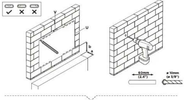
Option 2. Concrete/brick Installation
Using the bubble level (V) to ensure straightness, hold the Wall Template (U) to the wall at the required mounting height determined by step 3. Identify the 4 outermost holes (located at each corner) and mark the center of the holes with a pencil. Use a 3/8" (10mm) drill bit to drill pilot holes on the wall with a depth of 2.4" (60mm). Please note, failure to drill pilot holes may result in the lag bolt heads snapping during installation, or stone cracking/crumbling Never drill into the mortar in between the blocks, make sure that the anchors are seated flush with the concrete surface.
Carefully clear any dust or debris from inside the drilled holes and insert all 4 Plastic Wall Anchors (W-B). Holding the mount to the wall aligned with the pilot holes install Washer (W-C) and Lag Bolts (W-A) and tighten securely. Do not overtighten. Overtightening can damage the lag bolts or the wall, greatly reducing their holding power.
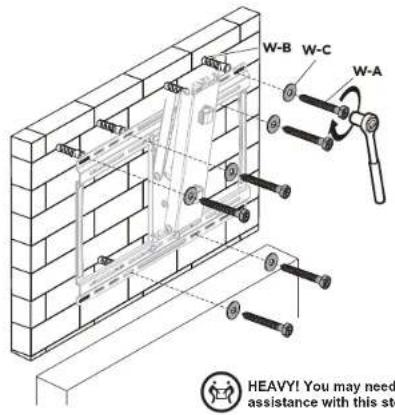
WARNING: Tighten screws so that wall plate is firmly attached, but do not overtighten. Overtightening can damage screws, greatly reducing their holding power.
Step 5
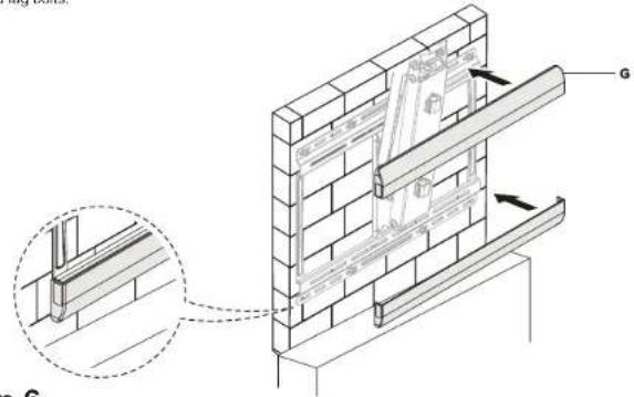
Attaching The Decorative Plates
Install Decorative Cover (G) as shown over the top and bottom of the wall bracket, covering the now installed lag bolts.
Step 6
Attaching The Vesa Brackets To The TV
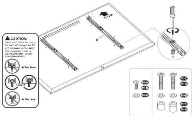
Lay your display face down on a soft, flat, or even surface to prevent damage, and place the VESA Bracket (D) over the bolt holes on the rear of the TV so that the VESA Brackets (D) are aligned with one another and not hanging over the top or bottom of the screen. Select the appropriate size mounting bolt for your display's mounting holes and verify the length of the VESA bolt is not too long. If you are unsure of the correct bolt size for your display refer to your TV user manual or contact the TV manufacturer for sizing information. If necessary use the included spacers (M-F or M-G) between the mount and the TV as shown above to adjust the length of the mounting bolt. Multiple spacers can be used in combination to achieve the desired bolt depth. Square Washer (M-E) must be used in all configurations.
MOUNT-IT!
Step 7 Step 9
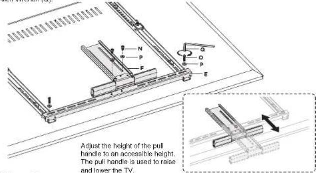
Attaching the pull handle
a. Attach the Cross Bar (E) to the VESA Brackets (D) using Washer (P) and Bolt (O). Tighten securely using Allen Wrench (Q).
b. Attach Pull Handle (F) to the Cross Bar (E) using Washer (P) and Bolt (N). Tighten securely using Allen Wrench (Q).
Step 8
Attaching TV To The Spring Arm
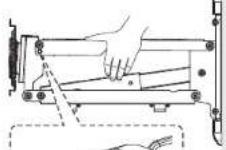
a. Insert the Allen Key into the hole as shown to prevent the end of the mount from moving when you are hanging the TV.
CAUTION: FAILURE TO FIX THE SPRING ARM POSITION BY INSERTING ALLEN KEY
(Q) MAY RESULT IN INJURY "
b. To attach the TV to the mount, remove the Nut (D1) pictured, lower the latch as shown. Once lowered, attach the VESA bracket to the TV Plate. Raise the latch up and reinstall nut (D1) to secure the TV in place.
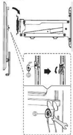

HEAVY! You may need assistance with this step.
Adjusting the spring arm tension
The tension of the spring arm must match the weight of the TV for easy height adjustment of the TV. The spring arm tension is set at the lowest level as factory default. Depending on the weight of the TV, the spring arm tension may need to be increased.
Note: Omitting spring arm tension adjustment may result in your TV not staying in the desired position.
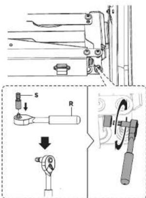
Note: Use the included ratchet wrench(R) and ratchet bit(S) to adjust the tension adjustment. To increase the tension (heavier TV) rotate the Ratchet wrench clockwise(multiple rotations might be required to reach the adequate spring tension level.)
To decrease the tension (lighter TV) rotate the Ratchet wrench (R) counter-clockwise (multiple rotations might be required to reach the adequate spring tension level.)
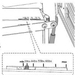
Note: The spring tension indicator will show the current weight setting of the spring arm.

Please scan this QR code for a video guide to adjust the spring arm tension
Step 10 Step 11
Cable Management
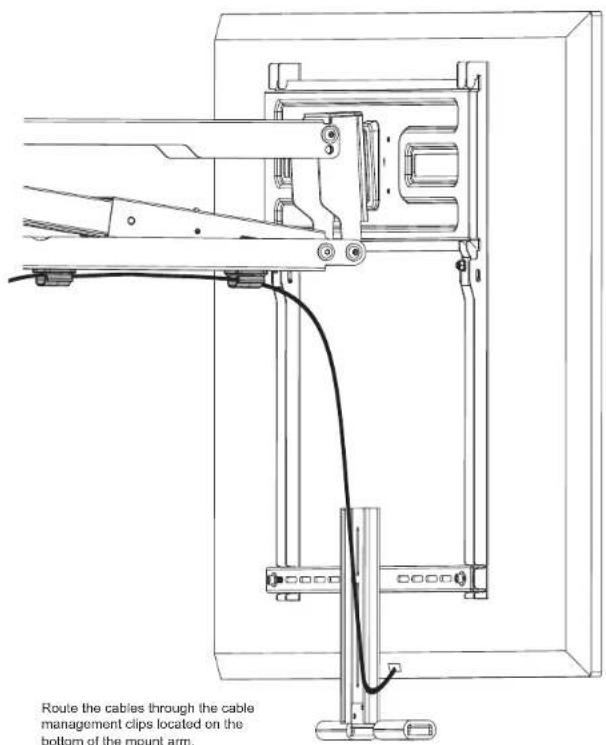
Positioning The TV
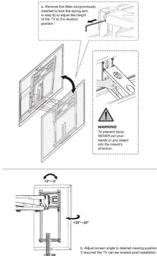
a. Remove the Allen kay(previously inserted to lock the spring arm in step 8) to adjust the height of the TV to the desired position "
To prevent injury NEVER put your hands or any object into the mount's structure.
b. Adjust screen angle to desired viewing position. If required the TV can be leveled post installation.
DIMENSIONS & WEIGHT CAPACITY
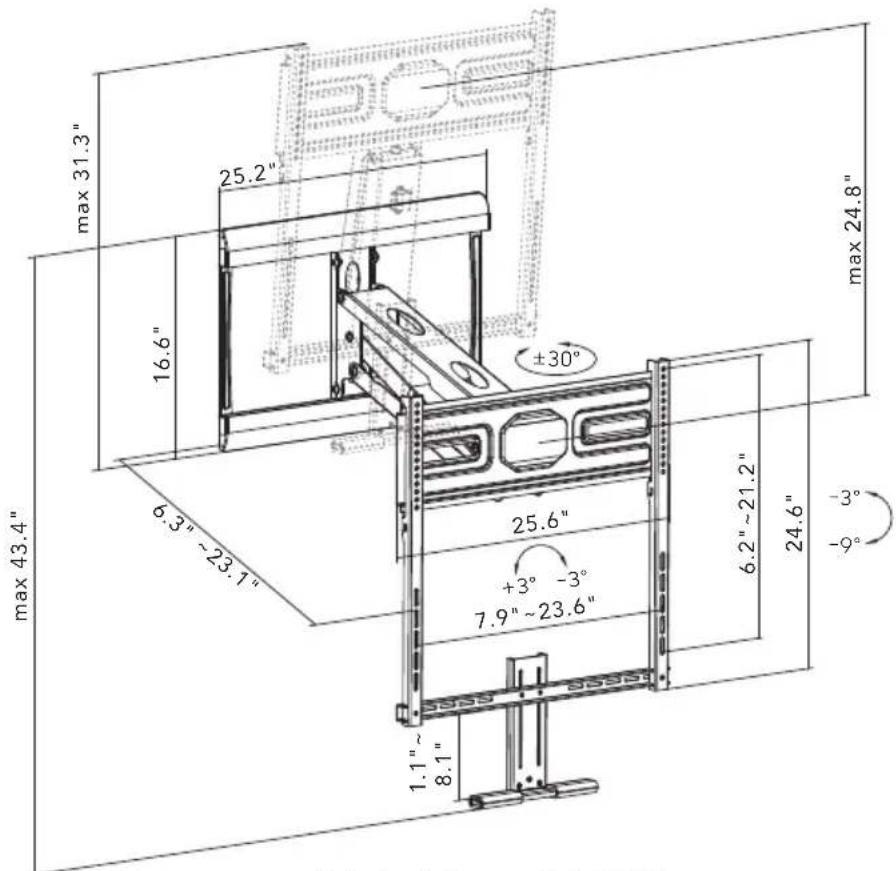
Rated weight capacity is 72.6lbs.
Caution:
Ensure all mounting surfaces are capable of holding the weight of your mount.
DO NOT EXCEED MAXIMUM LISTED WEIGHT CAPACITY. SERIOUS INJURY OR PROPERTY DAMAGE MAY OCCUR
Visit us at www.mount-it.com for product registration and warranty information.
Our US based customer service team is standing by to answer any questions you have about your Mount-It! product.
Available by phone Monday - Friday from 8:00am to 4:00pm PST.
Chat live with an agent on our website!

support@mount-it.com

(855) 925-5668

www.mount-it.com
- FIREPLACE TV MOUNT
- Thank you for choosing Mount-It!
- Step 1 Step 3
- Installing The Spring Arm To The Wallplate
- Step 2
- Installing The TV Bracket To The Spring Arm
- Attaching The Plastic Plate To The TV Bracket
- Positioning The Mount Over The Fireplace
- Step 4
- Option 1. Wood Studs Installation
- Option 2. Concrete/brick Installation
- Step 5
- Attaching The Decorative Plates
- Step 6
- Attaching The Vesa Brackets To The TV
- MOUNT-IT!
- Step 7 Step 9
- Attaching the pull handle
- Step 8
- Attaching TV To The Spring Arm
- Adjusting the spring arm tension
- Step 10 Step 11
- Cable Management
- Positioning The TV
- DIMENSIONS & WEIGHT CAPACITY
- Caution:
Brand : Mount-It!
Model : MI-395
Category : Support pour écran plat