MI-14002 - Flat Screen Mount Mount-It! - Free user manual and instructions
Find the device manual for free MI-14002 Mount-It! in PDF.


| Product Type | Flat Panel Wall Mount |
| Brand | Mount-It! |
| Model | MI-14002 |
| Compatible Screen Sizes | 32" to 65" |
| VESA Compatibility | 100x100mm to 600x400mm |
| Weight Capacity | 100 lbs (45.4 kg) |
| Mount Type | Fixed / Tilt / Full Motion (specify if known) |
| Tilt Range | +5° to -15° |
| Swivel Range | ±90° |
| Level Adjustment | ±3° |
| Wall Plate Dimensions | 15" x 6" (381 x 152 mm) |
| Mount Depth | 2.5" to 18" (63.5 to 457 mm) |
| Material | Heavy-gauge steel |
| Color | Black |
| Installation | Professional installation recommended |
| Tools Required | Stud finder, drill, socket wrench |
| Included Accessories | Mounting hardware, bubble level, cable management |
| Warranty | Limited lifetime warranty |
Frequently Asked Questions - MI-14002 Mount-It!
User questions about MI-14002 Mount-It!
0 question about this device. Answer the ones you know or ask your own.
Ask a new question about this device
Download the instructions for your Flat Screen Mount in PDF format for free! Find your manual MI-14002 - Mount-It! and take your electronic device back in hand. On this page are published all the documents necessary for the use of your device. MI-14002 by Mount-It!.
USER MANUAL MI-14002 Mount-It!
natural_image
Technical line drawing of a mechanical assembly with four arms and central housing (no text or symbols)
Scan this QR code for product information, videos, and assembly assistance.

UL CERTIFIED FULL MOTION TV WALL MOUNT

HAVE QUESTIONS?
Monday - Friday from 8:00am - 4:00pm PST

support@mount-it.com

(855) 925-5668

www.mount-it.com
Thank you for choosing Mount-It!
VESA MOUNTING HARDWARE
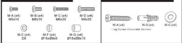
Check carefully to make sure there are no missing or defective parts. Some hardware provided may not be used. Use the correct mounting hardware suitable for your installation.
CHOKING HAZARD. Package includes small parts.
Not for children under 3 years. Adult supervision is required.
Missing Parts? Call us at (855) 925-5668 and we will ship replacement parts free of charge.
DIMENSIONS & WEIGHT CAPACITY
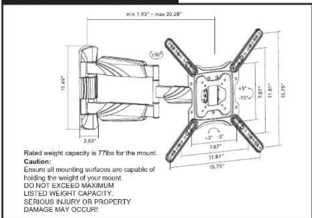
Step 1
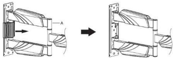
Remove the Decorative Cover
- Remove the preinstalled decorative cover from the middle of the wall bracket on Mount Arm (#A) to allow access to the bolt hole beneath.
natural_image
Mechanical assembly diagram showing a rotating component with labeled section A, before and after assembly (no text or symbols present)Step 2
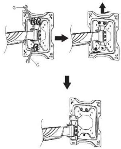
Remove the VESA Plate
- As shown in the diagram, loosen the top two nuts on the rear of the VESA plate, and remove the single nut on the lower half (save this nut for the reinstallation of the plate later.) Lift the VESA plate up and off of the Mount Arm (#A).
Step 3
A. Wood Stud Installation Option
- Using a stud finder locate the stud and center the Mount Arm (#A) on the stud at the desired height. Use the Bubble Level (#F) to ensure straightness and mark the center of the 3 mounting holes indicated here with a pencil. - Use a 3/16" drill bit and drill on the marked locations to a depth of 2.2". Secure the Mount Arm (#A) to the wall using 3 Lag Screws (#FW-A) and Washers (#FW-C). Tighten the screws until secure.

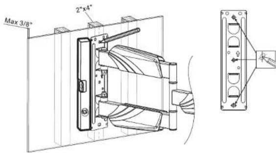
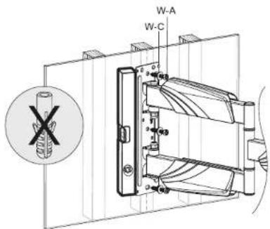

B. Concrete/Brick Mounting Option
- Use a bubble level to ensure straightness and hold the Mount Arm (#A) to the desired location on the wall. Mark the center of the 4 mounting holes indicated here with a pencil. - Use a 3/8" drill bit and drill on the marked locations to a depth of 2.4". Clear any dust and debris from the holes and insert the Concrete Anchors (#W-B). Secure the Mount Arm (#A) to the wall using Lag Screws (#W-A) and Washers (#W-C). Tighten the screws until secure.
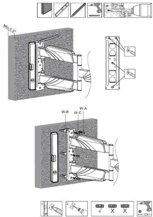
Step 4
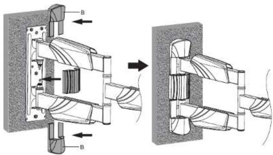
Install the Decorative Covers
- Reinstall the middle cover removed in step 1. - Install the Decorative Covers (#B) on the top and bottom of the wall bracket.
natural_image
Mechanical assembly diagram showing a shaft and housing with labeled components (no text or symbols present)Step 5
Optional Installation of the VESA Extension Arms
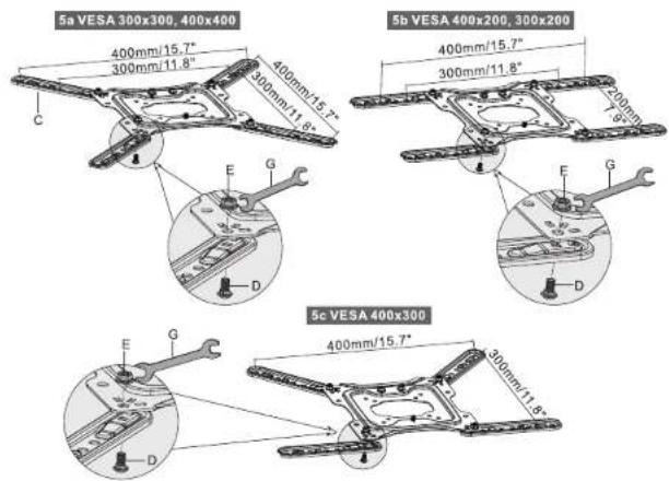
- For TVs with a VESA pattern greater than 200x200, the use of the VESA Extension Arms (#C) will be required. Follow the orientation shown in diagrams 5a, 5b, or 5c for the configuration that matches your TV. Secure the Extension Arms to the VESA Plate using the VESA Arm Bolts (#D) and VESA Arm Nuts (#E). Ensure that they are tightened until secure.
Step 6
Attach the TV
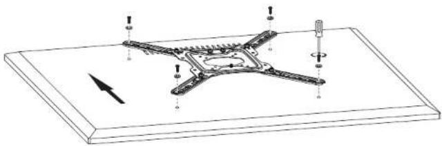
- Select the appropriate size mounting bolt (Select one size #M-A, M-B, M-C, or M-D) and washer (#M-E) for your display's mounting holes and verify the length of the VESA bolt is not too long. If you are unsure of the correct bolt size for your display refer to your display's user manual or contact the display's manufacturer for sizing information. If necessary, use the included spacers (#M-F, M-G) between the mount and the screen as shown above to adjust the length of the mounting bolt. Multiple spacers can be used in combination to achieve the desired bolt depth. - Attach the VESA Plate using the selected bolts in the orientation shown here and tighten until secure. Do not over tighten.


natural_image
Technical line drawing of a mechanical component with mounting holes and a directional arrow (no text or symbols)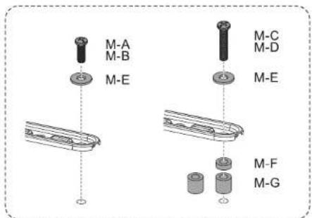
Step 7
Hang the TV on the Wall Mount
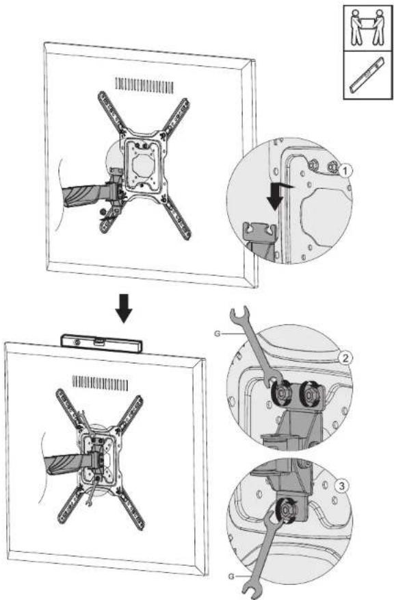
- Hang the TV back on the end of the Mount Arm by hooking the top two bolts into the slots on top of the arm.
- Use a bubble level to ensure the TV is level, then tighten the two nuts on the top back down using the Wrench (#G).
- Reinstall and tighten the lower nut removed in step 2 using the Wrench (#G).
Step 8
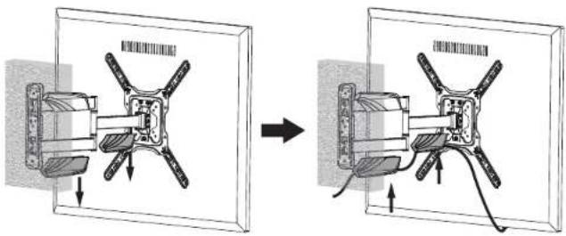
Cable Management
- Route the cables thought the cable clips on the underside of the arm segments.
natural_image
Diagram showing two mechanical assembly states with arrows indicating motion, no text or symbols presentStep 9
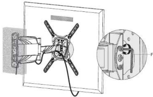
Tilt Adjustments
• To adjust the tilt of the screen loosen the bolt on the side the mount (indicated in the magnification bubble) using the Hex Wrench (#F) then tilt the screen to the desired angle and tighten the bolt back down.
natural_image
Technical diagram of a mounted device with cable and mounting bracket, showing internal components and a close-up view of a mechanical component (no text or symbols)Step 10
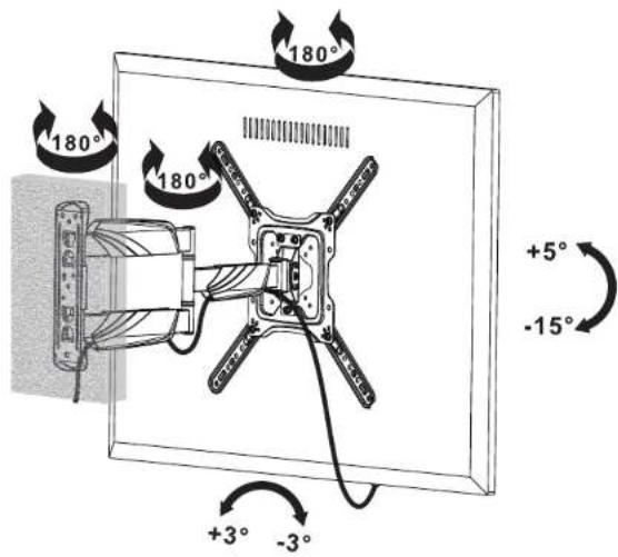
Final Adjustments
• Each arm joint can be turned 180° to fold and extend the arm.
• The screen can be tilted up and down +5°/-15°
Visit us at www.mount-it.com for product registration and warranty information.
Our US based customer service team is standing by to answer any questions you have about your Mount-It! product.
Available by phone Monday - Friday from 8:00am to 4:00pm PST.
Chat live with an agent on our website!

support@mount-it.com

(855) 925-5668

www.mount-it.com
- UL CERTIFIED FULL MOTION TV WALL MOUNT
- Thank you for choosing Mount-It!
- Step 1
- Remove the Decorative Cover
- Step 2
- Remove the VESA Plate
- Step 3
- Wood Stud Installation Option
- Concrete/Brick Mounting Option
- Step 4
- Install the Decorative Covers
- Step 5
- Optional Installation of the VESA Extension Arms
- Step 6
- Attach the TV
- Step 7
- Hang the TV on the Wall Mount
- Step 8
- Cable Management
- Step 9
- Tilt Adjustments
- Step 10
- Final Adjustments
Brand : Mount-It!
Model : MI-14002
Category : Flat Screen Mount