MI-14010 - Support pour écran plat Mount-It! - Free user manual and instructions
Find the device manual for free MI-14010 Mount-It! in PDF.


| Product Type | Flat Screen Wall Mount |
| Brand | Mount-It! |
| Model | MI-14010 |
| Compatible Screen Sizes | 26 to 55 inches |
| VESA Compatibility | 100x100, 200x100, 200x200, 300x200, 300x300, 400x200, 400x400 mm |
| Weight Capacity | 80 lbs (36 kg) |
| Tilt Range | -5° to +15° |
| Swivel Range | ±45° |
| Level Adjustment | ±3° |
| Distance from Wall | 1.5 to 18 inches (3.8 to 45.7 cm) |
| Material | High-grade steel |
| Mounting Type | Dual stud wall plate |
| Installation Hardware Included | Yes, all necessary bolts and wall anchors |
| Wall Plate Dimensions | 16.5 x 4.5 inches (42 x 11.4 cm) |
| Product Weight | 6 lbs (2.7 kg) |
| Color | Black |
| Security | Locking knobs to prevent screen tilt/swivel drift |
| Maintenance | Periodically check bolt tightness; clean with dry cloth |
| Spare Parts Availability | Contact customer support for replacement parts |
| Warranty | Limited lifetime warranty |
Frequently Asked Questions - MI-14010 Mount-It!
User questions about MI-14010 Mount-It!
0 question about this device. Answer the ones you know or ask your own.
Ask a new question about this device
Download the instructions for your Support pour écran plat in PDF format for free! Find your manual MI-14010 - Mount-It! and take your electronic device back in hand. On this page are published all the documents necessary for the use of your device. MI-14010 by Mount-It!.
USER MANUAL MI-14010 Mount-It!
natural_image
Technical line drawing of a mechanical assembly with mounting brackets and structural supports (no text or symbols)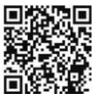
Scan this QR code for product information, videos, and assembly assistance.
HEAVY-DUTY FULL-MOTION TV WALL MOUNT

HAVE QUESTIONS?
Monday - Friday from 8:00am - 4:00pm PST

support@mount-it.com

(855) 925-5668

www.mount-it.com
Thank you for choosing Mount-It!
• The equipment is secured in the states' appropriates to their top assets. The product contracts and advances of equivalent par-gas professional 1. For material and costs more than 50 units nor less only some receivable are both, then return an additional or more as benefits
MONTENANCE: A reversion required (so more than the other), very low que in support was a discussion that was taken.
Mount and Accessories
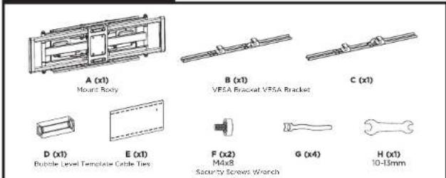
Mounting Hardware
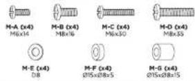
ware
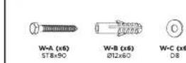
Check carefully to make sure there are no missing or defective parts. Some hardware provided may not be used. Use the correct mounting hardware suitable for your installation.
CHOKING HAZARD. Package includes small parts.
Not for children under 3 years. Adult supervision is required.
Missing Parts? Call us at (855) 925-5668 and we will ship replacement parts free of charge.
DIMENSIONS & WEIGHT CAPACITY
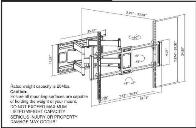
Step 1a
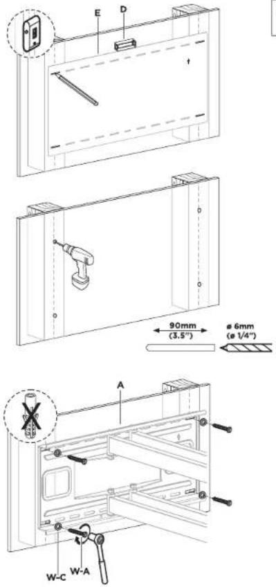
Wood Stud Installation Option
- Use a stud finder to locate the center of the studs and hold the Template (#E) to the wall in the desired mounting location.
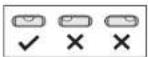
- Use a Bubble Level (#D) to ensure that the mount is level.
• Mark the center of the studs through the Template as shown. - Drill holes in the marked locations using a 1/4" drill bit (6mm) to a depth of 3.5" (90mm)
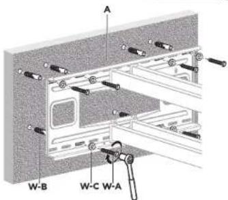
- Hold the Wall Mount (#A) to the wall over the holes, check the level once again, and install the 4 Lag Screws (#W-A) and Washers (#W-C) then tighten until secure.
Step 1b
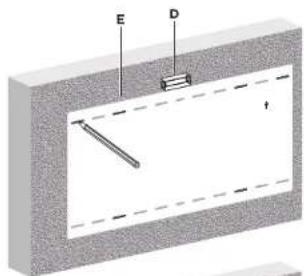
Concrete/Brick Installation Option
- Hold the Template (#E) to the wall in the desired mounting location.
- Use a Bubble Level (#D) to ensure that the mount is level.
- Mark the center of the studs through the Template as shown.
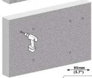
- Drill holes in the 6 marked locations using a 1/2" drill bit (12mm) to a depth of 3.7" (95mm).
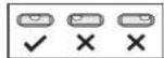
Note: Do not drill mounting holes into mortar (such as between bricks or stones) only drill and install into solid stone or concrete surfaces. - Clear dust or debris from the holes and insert the Concrete Anchors (#W-B) fully until flush with the wall. Hold the Wall Mount (#A) to the wall over the holes, check the level once again, and install the 6 Lag Screws (#W-A) and Washers (#W-C) then tighten until secure.
natural_image
3D diagram of a mechanical component with 95mm dimension label and 3.7" spacing (no readable text or symbols)
Step 2
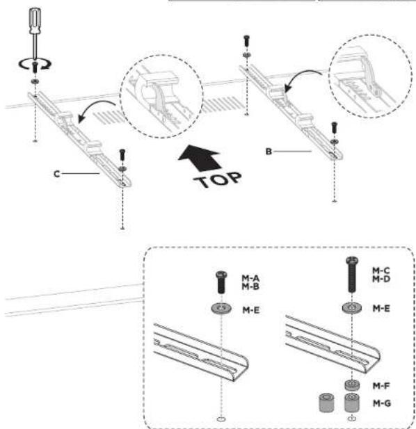
Attach the VESA Brackets to the TV
- Select the appropriate size mounting bolt (Select one size #M-A, M-B, M-C or M-D) and washer (#M-E) for your display's mounting holes and verify the length of the VESA bolt is not too long. If you are unsure of the correct bolt size for your display refer to your display's user manual or contact the display's manufacturer for sizing information. If necessary, use the included spacers (#M-F, M-G) between the mount and the screen as shown above to adjust the length of the mounting bolt.
- Attach the VESA Brackets (#B, #C) to the TV as shown using the selected bolts. The latches will be on the inside of the two arms for the majority of VESA configurations.

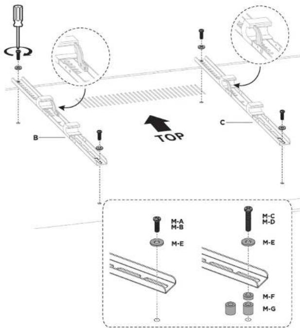
Attach the VESA Brackets to the TV: VESA 200x200
- Select the appropriate size mounting bolt (Select one size #M-A, M-B, M-C or M-D) and washer (#M-E) for your display's mounting holes and verify the length of the VESA bolt is not too long. If you are unsure of the correct bolt size for your display refer to your display's user manual or contact the display's manufacturer for sizing information. If necessary, use the included spacers (#M-F, M-G) between the mount and the screen as shown above to adjust the length of the mounting bolt. - Attach the VESA Brackets (#B, #C) to the TV as shown using the selected bolts. For VESA patterns 200x200, install in the configuration shown here so that the latches are facing the outside edges of the TV.

Step 3
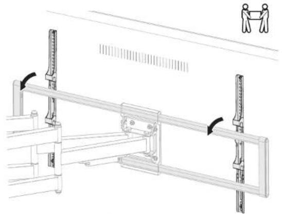
Hang the TV on the Wall Mount
- It is recommended that you use the assistance of a second person for this step. Hang the TV on the wall mount as shown so that the VESA brackets hook onto the top and bottom horizontal bars of the wall mount.
natural_image
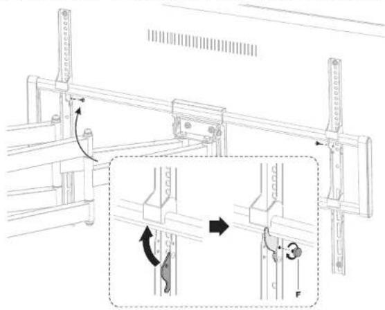
Technical line drawing of a mechanical assembly with two hanging objects, no text or symbols presentEngage the Latches
- Flip the latches up on both VESA Brackets, then secure them in place using the Security Screws (#F).
Step 4
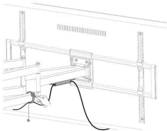
Cable Management
- Use the integrated cable management clips and the Cable Ties (#G) to route cables along the mount arm.
natural_image
Technical line drawing of a mechanical assembly with a clamped cable and a spring scale (no text or symbols)Level Adjustments
- To level the screen ± 5^ left or right, slightly loosen the 4 bolts shown here behind the TV, adjust to the desired level and then tighten the bolts back in place.
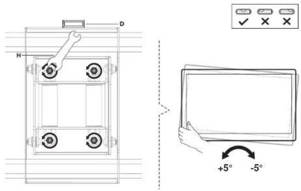
Tilt and Swivel Adjustments
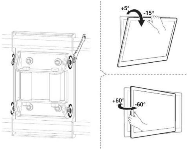
- To tilt the screen +5° and -15°, slightly loosen the 4 bolts shown here behind the TV, adjust to the desired level and then tighten the bolts back in place.
- The screen can swivel ±60° side to side.
Visit us at www.mount-it.com for product registration and warranty information.
Our US based customer service team is standing by to answer any questions you have about your Mount-It! product.
Available by phone Monday - Friday from 8:00am to 4:00pm PST.
Chat live with an agent on our website!

support@mount-it.com

(855) 925-5668

www.mount-it.com
- HEAVY-DUTY FULL-MOTION TV WALL MOUNT
- Thank you for choosing Mount-It!
- Step 1a
- Wood Stud Installation Option
- Step 1b
- Concrete/Brick Installation Option
- Step 2
- Attach the VESA Brackets to the TV
- Attach the VESA Brackets to the TV: VESA 200x200
- Step 3
- Hang the TV on the Wall Mount
- Engage the Latches
- Step 4
- Cable Management
- Level Adjustments
- Tilt and Swivel Adjustments
Brand : Mount-It!
Model : MI-14010
Category : Support pour écran plat