MI-2758 - Flat Screen Mount Mount-It! - Free user manual and instructions
Find the device manual for free MI-2758 Mount-It! in PDF.


| Product Type | Flat Screen Wall Mount |
| Brand | Mount-It! |
| Model | MI-2758 |
| Compatible Screen Sizes | 26" to 55" |
| VESA Patterns | 75x75mm, 100x100mm, 200x100mm, 200x200mm |
| Weight Capacity | Up to 77 lbs (35 kg) |
| Tilt Range | -15° to +5° (forward/backward) |
| Swivel Range | ±90° (left/right) |
| Level Adjustment | ±3° (post-installation) |
| Distance from Wall | 1.6" to 15.7" (variable depth) |
| Material | Heavy-duty steel with powder coat finish |
| Installation Type | Single stud or dual stud (wood or concrete) |
| Included Hardware | Mounting brackets, screws, wall anchors, bubble level |
| Cable Management | Integrated cable covers and clips |
| Safety Features | Locking mechanism to prevent accidental dislodging |
| Maintenance | Wipe with dry cloth; check screws periodically |
| Dimensions (WxHxD) | 20.5" x 12.2" x 2.0" (mount plate) |
| Net Weight | 6.5 lbs (2.9 kg) |
| Spare Parts | Contact Mount-It! for replacement hardware |
| Repairability | User-serviceable parts (screws, anchors); no electronic components |
| Certifications | TAA compliant, UL listed |
Frequently Asked Questions - MI-2758 Mount-It!
User questions about MI-2758 Mount-It!
0 question about this device. Answer the ones you know or ask your own.
Ask a new question about this device
Download the instructions for your Flat Screen Mount in PDF format for free! Find your manual MI-2758 - Mount-It! and take your electronic device back in hand. On this page are published all the documents necessary for the use of your device. MI-2758 by Mount-It!.
USER MANUAL MI-2758 Mount-It!
natural_image
Technical line drawing of a mechanical robotic arm with mounting flanges and a base platform (no text or symbols)
Scan this QR code for product information, videos, and assembly assistance.
FREESTANDING DUAL MONITOR ARM WITH HEIGHT ADJUSTMENT

HAVE QUESTIONS?
Monday - Friday from 8:00am - 4:00pm PST

support@mount-it.com

(855) 925-5668

www.mount-it.com
Thank you for choosing Mount-It!
EN Read the entire instruction manual before you start installation and assembly. If you have any questions regarding any of the instructions or warnings, please contact M:uri-U for assistance.
CAUTION: Live with products heavier than the rated weights indicated may result in inability causing possible injury. Please closely follow the assembly instructions. Improved medication may result in demand or serious personal injury.
- Safety gear and proper tools must be used. This product should only be installed by professionals.
- This product is designed to be installed on solid concrete walls, masonry walls or wood stud walls.
- Make sure that the supporting surface will safely support the combined weight of the equipment and all attached hardware and components. - Use the mounting screen provided and DO NOT OVER TIGHTEN mounting screws.
• This product contains small items that could be a choking hazard if swallowed. Keep these items away from children.
- This product is intended for indoor use only. Using this product outdoors could lead to product failure and personal injury.
MPORTAIN: Ensure that you have reserved air pants according to the component checked prior to installation. If any pants are missing or faulty, contact [1, 20] or for a replacement
MAINTENANCE: Check that the product is secure and sells to use at regular intervals (at least every three months).
RU 10 Period Initial workings and operations, which are not available to управления. Если we have been a key-neighbored social system in the construction of pre-provisional, discretionary or financial services.
A. 2023-10-16: The first time was to make sure what is the time in case, some were not included or similar to the same
Mount and Accessories
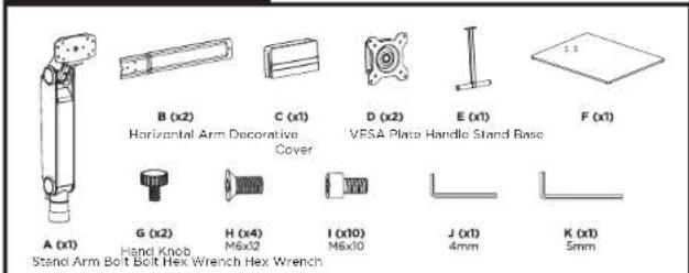
Mounting Hardware x2
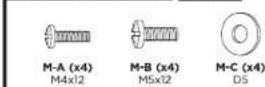
Check carefully to make sure there are no missing or defective parts. Some hardware provided may not be used. Use the correct mounting hardware suitable for your installation.
CHOKING HAZARD. Package includes small parts. Not for children under 3 years. Adult supervision is required.
Missing Parts? Call us at (855) 925-5668 and we will ship replacement parts free of charge.
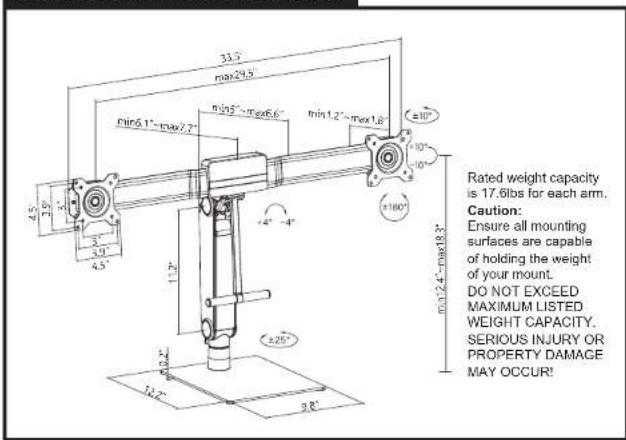
DIMENSIONS & WEIGHT CAPACITY
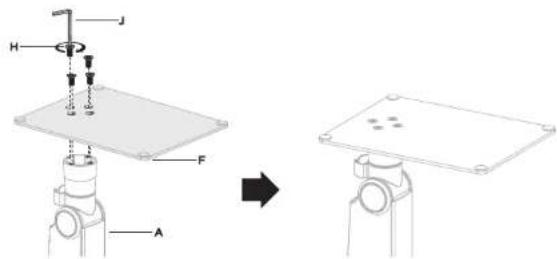
Step 1
Connect the Base and Arm
- Connect the Stand Base (#F) to the bottom of the Stand Arm (#A) using the Bolts (#H) and tighten until secure using the 4mm Hex Wrench (#J)
Step 2
Assemble the Monitor Arm
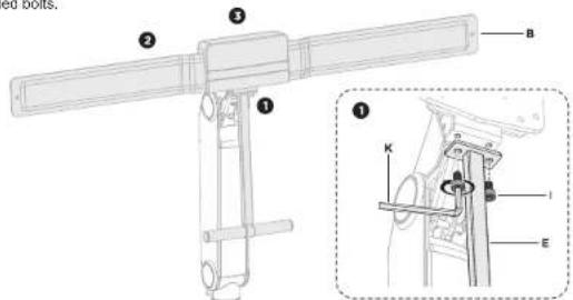
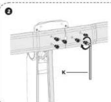
- Attach the Handle (#E) to the lower bolt holes on the stand arm using Bolts (#I) and tighten using Hex Wrench (#K)
- Attach the Horizontal Arm (#B) to the front of the stand arm using Bolts (#I) and tighten using Hex Wrench (#K)
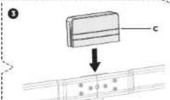
- Place the Decorative Cover (#C) over the middle of the horizontal arm so that it fully covers the installed bolts.
Note:
Attach the decorative cover to the crossbar as shown, make sure the decorative cover is facing the front.
Step 3
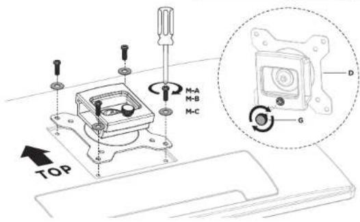
Attach the VESA Plates to the Monitors
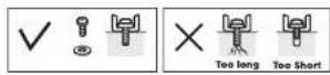
- Select the appropriate size mounting bolt (#M-A, M-B) and washer (#M-C) for your monitors mounting holes and verify the length of the VESA bolt is not too long. If you are unsure of the correct bolt size for your display refer to your monitor user manual or contact the monitor manufacturer for sizing information. Attach the VESA plate to the back of each monitor using the selected bolts and washers in the orientation shown here.
- Insert the Hand Knobs (#G) into the bolt holes on the back of the VESA Plates.
Step 4
Attach the Monitors to the Horizontal Arm
- Slide the brackets on the back of the VESA Plates onto the ends of the Horizontal Arm. Once the monitors are in the desired positions fix them in place by tightening the hand knob installed in the previous step 3.
- Once the VESA Plates are on the arm, install 1 each of the Bolts (#1) to the end of each arm to prevent the monitor from being accidentally removed.
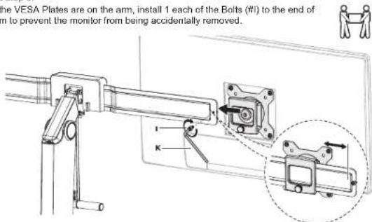

Caution: Keep a hand on the stand when mounting the monitors to prevent the stand from tipping. Identical monitors should be used to prevent balance issues.
Step 5
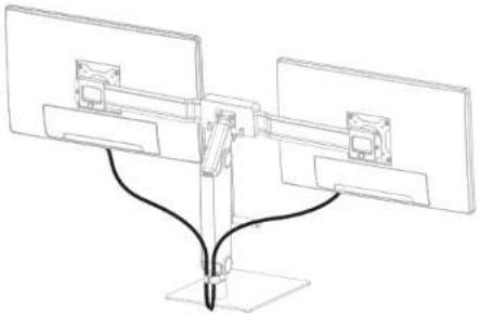
Cable Management
• Monitor cables can be routed through the cable clip on the back of the arm.
natural_image
Pure technical line drawing of a mechanical assembly with no text, numbers, or symbolsStep 6
Final Adjustments
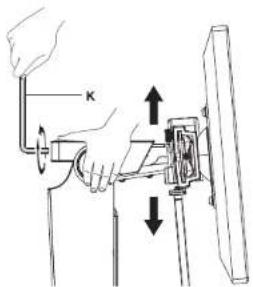
To properly balance the arm with monitors mounted, adjust the spring tension using the supplied Allen Key as follows:
First, position and firmly hold the arm horizontally as shown. Ask for assistance should you require it.


CAUTION: To avoid damage to monitors or mount, always keep the arm in a horizontal position while making adjustments. Again, ask for assistance if required.
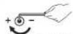
If the arm drops, turn the adjustment screw clockwise until it stays in a horizontal position.
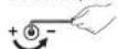
if the arm rises, turn the adjustment screw counter-clockwise until it stays in a horizontal position.

CAUTION: DO NOT over tighten the screws.
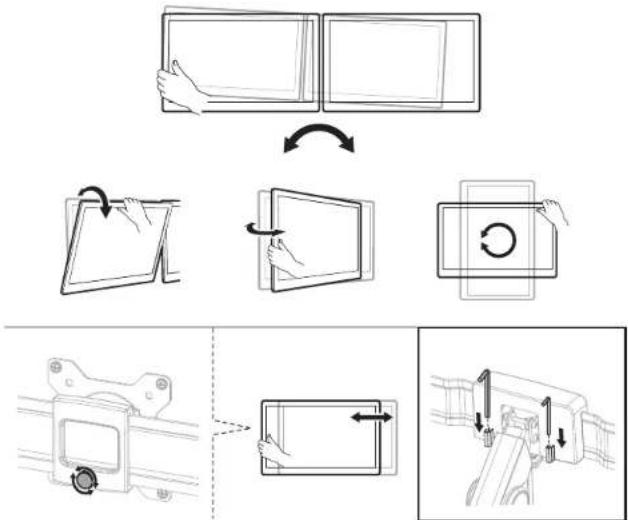
- The monitors can be turned left to right +/- 25°, tilted forward or back +10°/-10° and rotated 90° to alternate between landscape and portrait orientations. - The monitors can be slid left to right on the horizontal arm by loosening the hand knob on the back of the VESA plate, adjusting to the desired location and then tightening the knob back down. - Stow the Hex Wrenches on the back of the decorative cover for convenient access.
flowchart
graph TD
    A["Hand Holding Panel"] --> B["Rotate Screen"]
    B --> C["Rotate Board with Circular Loop"]
    C --> D["Mounting System"]
    D --> E["Close-up Panel with Arrow Down"]
    E --> F["Arrow Down to Panel"]
Visit us at www.mount-it.com for product registration and warranty information.
Our US based customer service team is standing by to answer any questions you have about your Mount-It! product.
Available by phone Monday - Friday from 8:00am to 4:00pm PST.
Chat live with an agent on our website!

support@mount-it.com

(855) 925-5668

www.mount-it.com
Brand : Mount-It!
Model : MI-2758
Category : Flat Screen Mount