
HGA604FKSS - Cooker Robinhood - Free user manual and instructions
Find the device manual for free HGA604FKSS Robinhood in PDF.


| Product Type | Gas Cooktop |
| Model | HGA604FKSS |
| Brand | Robinhood |
| Overall Dimensions (W x D) | 600 mm x 600 mm (nominal cutout size) |
| Cutout Dimensions (W x D) | 560 mm x 480 mm (approximately) |
| Burner Configuration | 4 burners: 1 Auxiliary (small), 2 Semi-rapid (medium), 1 Rapid (large) |
| Gas Types | Natural Gas (1.0 kPa) or Universal LPG (2.75 kPa) |
| Gas Connection | ½ BSP male, flexible hose (max 1.2 m) or rigid pipe |
| Electrical Supply | 220-240 V, 50/60 Hz (standard Australian/New Zealand) |
| Power Consumption | Less than 1 W (electronic ignition only) |
| Ignition | Electronic spark ignition with safety valve |
| Safety Features | Flame failure safety device (automatic gas shut-off if flame extinguishes); child lock not mentioned |
| Burner Output (Natural Gas) | Auxiliary: 3.8 MJ/h, Semi-rapid: 5.7 MJ/h, Rapid: 9.3 MJ/h |
| Burner Output (LPG) | Auxiliary: 3.8 MJ/h, Semi-rapid: 5.7 MJ/h, Rapid: 9.3 MJ/h |
| Nozzle Sizes (NG) | Auxiliary: 0.90 mm, Semi-rapid: 1.10 mm, Rapid: 1.40 mm |
| Nozzle Sizes (LPG) | Auxiliary: 0.55 mm, Semi-rapid: 0.70 mm, Rapid: 0.90 mm |
| Material | Stainless steel surface with enameled parts (some models) |
| Cleaning | Non-abrasive cleaners; burners and grids removable; clean electrodes and probes |
| Installation Requirements | Authorized personnel only; 30 mm clearance below; 50 mm from rear wall; 100 mm from side walls; 650 mm above to hood/cupboard; heat baffle required |
| Warranty | 24 months domestic use (parts and labor) in New Zealand/Australia; excludes misuse, wear, etc. |
| Weight | Approximately 12 kg (based on similar products) |
Frequently Asked Questions - HGA604FKSS Robinhood
User questions about HGA604FKSS Robinhood
0 question about this device. Answer the ones you know or ask your own.
Ask a new question about this device
Download the instructions for your Cooker in PDF format for free! Find your manual HGA604FKSS - Robinhood and take your electronic device back in hand. On this page are published all the documents necessary for the use of your device. HGA604FKSS by Robinhood.
USER MANUAL HGA604FKSS Robinhood
Description: Robinhood Gas Cooktop 60cm and 90cm
Model Numbers: HGA604FKSS, HGAA604FKSS, HGA905FKSS


TO BE INSTALLED BY AN AUTHORISED PERSON
THESE INSTRUCTIONS CONTAIN IMPORTANT INFORMATION ABOUT INSTALLATION AND USE
Warning and Safety Information
This appliance shall be installed only by authorised persons and in accordance with local and national building instructions, local gas fitting regulations, municipal building codes, electrical wiring regulations and AS 5601-2010 Gas Installations and any other statutory regulations.
This appliance is not intended for use by persons (including children) with reduced physical, sensory or mental capabilities, or lack of experience and knowledge, unless they have been given supervision or instruction concerning use of the appliance by a person responsible for their safety. Children should be supervised to ensure that they do not play with the appliance.
Do not leave this cooktop unattended or unsupervised whilst children or the infirmed are present.
! Accessible parts will become hot when in use and directly after use, care should be taken to avoid touching the burners. To avoid burns and scalds keep children away.
The cooktop is intended for installation into a benchtop above a kitchen cabinet of min 600mm width or more.
Incorporation of a oven under the cooktop is permissible for ovens equipped with a cooling fan.
If the power supply cable is damaged, it must be replaced by the manufacturer or its service agent or similarly qualified person to avoid a hazard.
Always unplug the appliance before carrying out any maintenance operations or repairs.
If a stationary cooktop is not provided with a supply cord and a plug or by other means of disconnection from the supply having an air gap contact the separation in all active (phase) conductors, the instructions shall state that such means for disconnection shall be incorporated in the fixed wiring according to the wiring rules.
Do not install the appliance near flammable materials (e.g.. curtains).
The appliance must be housed in heat resistant units.
The walls of the units must not be higher than work top and must be capable of resisting temperatures of 75° C above temperature.
Igniting the Burners
In these models the knob controls both ignition and the safety device. Proceed as follows to ignite the burners:
1) Depress the chosen knob and turn to the large flame.
2) Keep the knob depressed for 3 to 4 seconds to allow the spark to ignite the burner and to heat the safety device.
3) Release the knob after about 3 to 4 seconds and adjust the flame to the desired setting by rotating the knob anti-clockwise. Repeat steps 1 to 3 if the flame does not ignite.
1) The OFF position is identified by a black dot. To shut off a burner depress the control knob and turn the knob clockwise to the OFF position.

Using the Burners
For greater efficiency and less gas consumption use pots and pans with the right diameters for the burners. Avoid having flames extending out from underneath the pans (see table).
| Recommended Cookware Sizes (cms) | |
| Burner Cookware Diameter | |
| Auxiliary | 8 to 14cms |
| Semi Rapid | 14 to 20cms |
| Rapid | 20 to 28cms |
| Triple Ring | Above 26cms |
Automatic Safety Valves
In the event the flame is extinguished during operation, the safety device will automatically shut off gas to the burner.
![graph TD A["Top Row Circle"] --> B["Left Column"] A --> C["Right Column"] A --> D["Bottom Row Circle"] E["Left Column"] --> F["Left Column"] E --> G["Right Column"] E --> H["Bottom Row Circle"] I["Left Column"] --> J["Left Column"] I --> K["Right Column"] I --> L["Bottom Row Circle"] M["Left Column"…](/content/2026/05/997356/images/eecd9a41408174761bb57c34a56f7749c389b608fcb5177877d84f2776348b0b.jpg)

![graph TD A["Top Grid"] --> B["Left Circular Component"] A --> C["Right Circular Component"] A --> D["Bottom Circular Component"] B --> E["Arrow Right"] C --> F["Arrow Left"] D --> G["Arrow Left"] style A fill:#f9f,stroke:#333 style B fill:#ccf,stroke:#333 style C fill:#ccf,stroke:#333 style D fill:#…](/content/2026/05/997356/images/0a3c754b2b3428f05483fb3e279e1f14858bc4bd750b7183d810a97a99e6e0a6.jpg)
This logo represents the burner this knob controls (i.e right front in this instance)


CLEANING AND MAINTENANCE
General
Cleaning and maintenance should be carried out regularly while the appliance is cold especially when cleaning the enamelled & Stainless steel parts.
Avoid leaving alkaline or acid substances on the surfaces (lemon juice, vinegar etc).
Avoid using acid or chlorine based cleaning products.
Enamelled Parts (only available in some models)
All of the enamelled parts must be washed only with a sponge and soapy water or non abrasive products.
Burners and Grids
These parts can be removed and cleaned with appropriate products.
After cleaning, the burners and their flame distributors must be well dried and correctly replaced.
It is very important to check that the burner flame distributor (F) and the cap (C) has been correctly positioned (fig.6), failure to do so can cause serious problems.
Check that the electrode (S) is always clean to ensure trouble free ignition.
Check that the probe (T) is always clean to ensure correct operation of the safety valves (for models with safety device).
Both the probe and ignition plug must be very carefully cleaned.

Operating Instructions
Gas Taps

Periodic lubrication of the gas taps must be carried out by authorised personnel only. In the event of operating faults with the gas taps call an authorised service agent.
General Advice
- When the appliance is not being used it is advisable to keep the gas tap closed.
• Abnormal operation which may require service can be identified by black sooting of cooking utensils or an irregular flame which is yellow or unstable.
• These service operations must be carried out by an authorised service agent only.
Triple Ring Burner
The triple ring burner must be correctly positioned and must be engaged in the lodgement as shown by the arrow (fig.7). In the correct position the burner must not rotate (fig.8). Position the cap (A) and the ring (B) as shown in (fig.8).
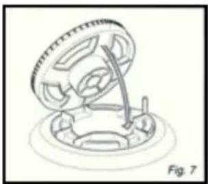

Cleaning the Triple Ring Burner
Pay special attention to this burner as the four holes around the outside of the crown must always be kept clean. When cleaning, remove the flame divider (fig.9) and use a cotton bud, toothbrush or similar item to clean out any incrustations or dirt from the four holes marked (H) as shown in (fig.10).
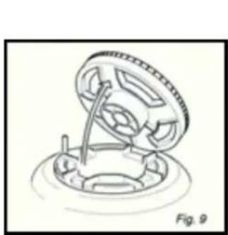


WARNING!
- Do not spray aerosols in the vicinity of this appliance while it is in operation.
- Do not store or use flammable liquids or items in the vicinity of this appliance.
- Do not modify this appliance.
• This appliance must not be used as a space heater in any circumstances.
Cutout Dimensions

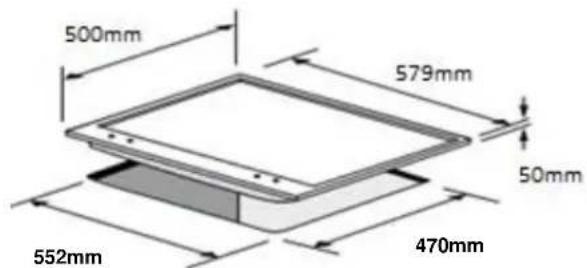
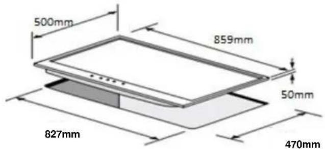


Foreword
These cooktops are designed to be embedded into kitchen fixtures measuring 600mm in depth.
In order to install the cooktop into the kitchen fixture, a hole with the dimensions shown on the cutting board has to be made, keeping in consideration the following:
- There must be a clearance of at least 30mm between the bottom side of the cooktop and the upper surface of any other appliance or internal shelf.
- Any adjoining wall surface situated within 200mm from the edge of the cooktop must be a suitable non combustible material for a height of 150mm for the entire length of the hob.
- The cooktop must be kept no less than 100mm away from any side wall.
• The hob must be installed at least 50mm from the rear wall. - There must be a distance of at least 650mm between the hob and any cupboard or extractor hood positioned immediately above.
• It is essential to install a heat baffle between the bottom of the cooktop and the underlying unit.


Installation in Kitchen Cabinet with Door (fig.13)
The fixture has to be made according to specific requirements in order to prevent the gas burners from going out, even when the flame is turned down to minimum, due to pressure changes caused by opening or closing cupboard doors. It is recommended that a 30mm clearance be left between the cooktop and the fixture surface (fig.13).
Settling the Hob for Installation
Every cooktop is provided with a set of foam strips for fitting to the unit with thickness from 3 to 4cm and a seal with adhesive on one side.
- Remove burners and grids.
- Turn the cooktop over and rest the glass side on a cloth.
• Apply the self adhesive seal (G) as shown in (fig.14).
• Slot the cooktop into the unit and position.
- Position the cooktop in the recess and secure by means of the brackets as shown in (fig.15) for 3 or 4cm work top.


Ventilation
• Ventilation must be in accordance with AS5601-2010 Gas Installations.
- The appliance should have adequate ventilation for complete combustion of gas, proper fluing and to maintain temperature of immediate surroundings within safe limits.
Discharging Products of Combustion
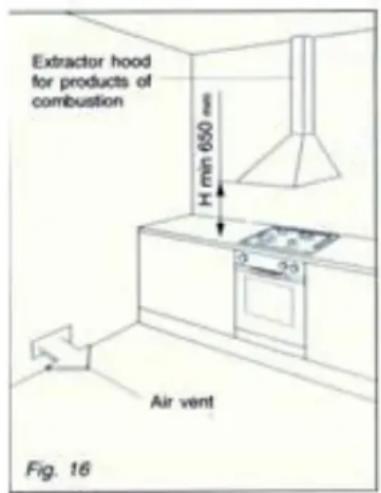
- Extractor hoods connected directly to the outside must be provided to allow safe discharge of combustible gas (fig.16).
- If this is not possible an electric fan attached to an external wall or the window may be used, the fan should have a capacity to circulate air at an hourly rate of 3-5 times the total volume of the kitchen (fig.17).
• The fan can only be installed if the room has suitable vents to allow air to enter (fig.17).

GAS SECTION
Gas Types
This appliance is approved for use with:
• Universal LPG – 2.75kPa
• Natural Gas – 1.0kPa
(Commissioning test point pressure is with all burners on large flame.)
Gas Connection

The appliance is predisposed and adjusted to operate with the gas indicated on the gas type label applied to the underside of the appliance.

This appliance is pre-set at the factory for Natural Gas.
If the appliance must be operated with a gas different than that indicated on the gas type label, it is necessary to execute the following gas conversion operation:
- Remove gas type label.
- Replace the injectors to suit the gas type (see nozzle table contained in this manual).
- Apply gas type label provided with the conversion kit.
- Adjust the operating pressure to suit the gas type.
- Regulate the bypass adjustment screw to set the minimum gas rate.
- To adjust the minimum flame setting, use a screw driver on the screw placed on the tap after removing the control knob. Turn the tap to its minimum setting and turn the screw to adjust (for LPG turn the screw tight).

THIS SHOULD ONLY BE CARRIED OUT BY AUTHORISED PERSONNEL!
Orientation of the Elbow
This appliance is supplied with a Gas Inlet elbow connection located below the maintop, at the rear. The actual location by measurement is 110mm from the right hand side of the 4 burner hob, and 50mm from the left hand side of the 5 burner hob.
The connection to the gas supply must be effected only from this side or in vertical position by turning the elbow downwards.
To turn the elbow, follow the directions below:
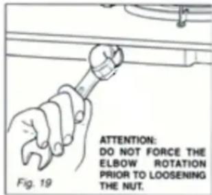
- Loosen the nut.
- Turn the elbow.
- Lock the nut.
• Never attempt to turn the elbow without having first slackened off the relative lock nipple.
• Make sure that there are no gas leaks by testing with a soapy solution.
• The seals are the elements that guarantees the seal in the gas connection. - It is recommended they be replaced whenever they show even the slightest deformation or imperfection.
The gas connection is male 1/2 " BSP.
The hotplate can be connected to the gas supply using rigid pipe OR a flexible hose assembly which is AGA certified to AS/NSZ 1869, 10mm ID, class B or D and the length must not exceed 1.2m.

WARNING!
Ensure the hose does not contact the hot surfaces of the hotplate, oven, dishwasher or other appliance that is installed underneath or next to the hotplate.
Ensure the hose assembly is restrained from accidental contact with the flue or flue outlet of an under bench oven. The hose should not be subjected to abrasion, kinking or permanent deformation and should be able to be inspected along its entire length.
• The supply connection point shall be accessible with the appliance installed.
• After connecting to the mains, check that the couplings are tight. Never use a naked flame to check for gas leaks.
• The connection with rigid pipes should not cause stresses to the appliance inlet and manifold.

Before Leaving
- Check all connections for gas leaks using a soapy solution – DO NOT use a naked flame to detect leaks.
- Ignite all burners both individually and concurrently to ensure correct operation of gas valves, burners and ignition.
• Turn gas taps to low flame position and observe stability of the flame for each burner individually and concurrently. - When satisfied with the hotplate, please instruct the user on the correction method of operation.
- If the appliance fails to operate correctly after all checks have been carried out, contact the authorised service provider.
- A data label is located on the bottom of the appliance. In the event the data label is not visible in the installed position, a duplicate data label is supplied to adhere in an accessible area next to the appliance.
Operations to be performed when the conducting the Gas Conversion
If the injectors are not supplied they can be obtained from the service agent.
- Remove the gratings and the burner covers
- Using the wrench, substitute the nozzle injectors (J) with a suitable type for the kind of gas for which it is to be used (see injector table).
- The burners are conceived in such a way so as not to require the regulation of the primary air.

Regulating the Burner Minimum Setting
When switching from one type of gas to another, the minimum flow rate must be correct so that the flame will not go when changing from maximum to minimum flame.
To regulate the flame follow the instructions below:
• Light the burner then turn the knob to low flame.
- Adjust the bypass screw to set the minimum flame.
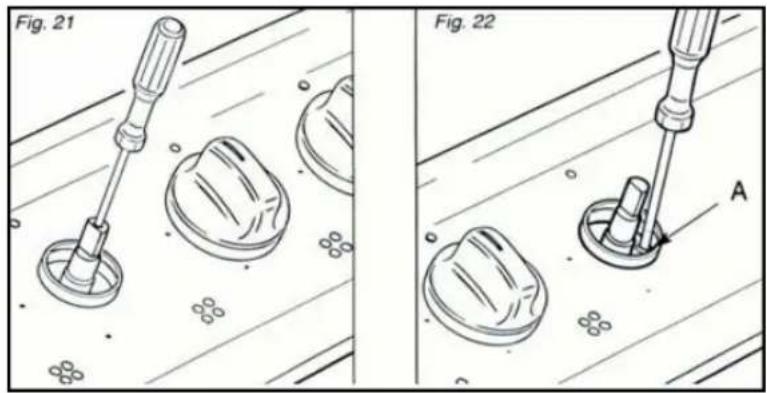
For gas valves with bypass adjustment screw in the centre of the shaft (fig.21)
• Using a screwdriver with maximum diameter 3mm, turn the screw inside the tap until the correct setting is obtained.
For gas valves with bypass adjustment screw on the valve body (fig.22)
• Turn the screw (A) to the correct setting with a screwdriver.
ELECTRICAL SECTION

Installation must be carried out according to instructions provided by the manufacturer.

The manufacturer accepts no responsibility for harm or damage to people, animals or objects caused by incorrect installation.

Connection to the electric power supply must be carried out by a qualified technician following the appropriate safety regulations.

Before carrying out the connection to the power supply, the voltage rating of the appliance must be checked for correspondence to the available mains supply voltage, the mains electric wiring should also be capable of handling the hob's power rating.

The power point must be connected to suitable earth wiring to conform to current safety regulations.

The power supply cord must not touch against any hot surfaces and must be placed so that it's temperature does not exceed 75° C at any point along its length.

The power switch or plug must be in an accessible position.
If the appliance is supplied without a plug a standard plug may be fitted. Be aware that the wiring colours in the hob cable may differ from the colours of your electrical plug. In any case the plug should be wired as follows:
- Connect the green/yellow wire to the terminal marked with the letter E or the earth symbol.
- Connect the blue wire to the terminal marked with the letter N or coloured black.
- Connect the brown wire to the terminal marked with the letter L or coloured red.

For connections to the mains power supply never use adapters, reductions or multiple power points as these may overheat and catch fire.
In the event that installation should require modifications to the mains supply wiring system or if the power plug is not suitable for the type of power point available, it is recommended that a qualified technician be called to carry out substitution.
The technician will also need to verify that the cross section of the electric cables on the power point match the appliances power rating.
Replacing the Power Supply Cable
• Use the same type of power supply cable.
• The cable must be connected to the terminal block following the diagram (fig.23).
• Supply cables – Type H05V2V2-F resistance to temperatures of 90° C.
- Connection to good earth wiring system is absolutely essential.
- The manufacturer accepts no responsibility for any inconvenience caused by failure to comply with this rule.

Burners and Nozzle Specifications
| Table1 | NG | U-LPG | ||
| Burner | NGC (MJ/h) | Nozzle (mm) | NGC (MJ/h) | Nozzle (mm) |
| Auxiliary (Small)(A) | 3.8 3.8 | 0.90 | 0.55 | |
| Semi rapid (Medium) | 5.7 5.7 | 1.10 | 0.7 | |
| Rapid(R) | 9.3 9.3 | 1.40 | 0.9 | |
| Triple Ring (TR) | 13.5 | 1.7 | 12.5 | 0.98 |
| Operating Pressure | 1.0kPa | 2.75kPa | ||
Descriptions and illustrations in this booklet are indicative only. The manufacturer reserves the right to make necessary modifications where needed.
Terms and Conditions
The following conditions apply in respect of the warranty given in this certificate:
- Monaco Corporation Limited (“Monaco”) warrants the following Robinhood products against manufacturing defects and faulty materials, under normal use and subject to the exclusions in this certificate, for a period of:
Rangehood, Ovens, Cooktops, Dishwashers - 24 months from date of original purchase for domestic use.
Uniduct - 12 months from date of original purchase for domestic use.
Ironing centre - 12 months from date of original purchase for domestic use.
Taps, including Pull-out and Mixer taps – 5 years on parts only from date of original purchase domestic for use, 24 months parts and labour from date of original purchase for domestic use
Sinks sets—5 years on stainless steel sink including draining bench from date of original purchase for domestic use, 6 months on all stainless steel accessories, including wire rack, colander and tray from date of original purchase for domestic use.
Laundry Tub - 5 years on stainless bowl, 24 months on Tap, Cabinet and other components from the date of original purchase for domestic use.
"Original purchase", when used in this certificate, means purchase by the customer directly from Monaco or one of its approved suppliers.
-
This warranty is limited to the repair or replacement, at our option, within the warranty period of any component part which we at our discretion determine to contain faulty materials or a manufacturing defect in breach of this warranty. This warranty is subject to terms and conditions set out in this certificate.
-
The warranty only applies within New Zealand.
-
The customer must produce the original invoice or other purchase documentation as proof of the original purchase date.
Warranty exclusions
- The warranty does not apply where, in Monaco's opinion:
The defect is caused by misuse, wear and tear, dirt, fire or accidental damage.
The product has been repaired or serviced by an unauthorised person.
The product was not installed in accordance with our instructions.
The product was purchased overseas or was not designed for use in New Zealand.
The product was not used, cleaned or cared for in accordance with our instructions.
The product was used outdoors.
- In addition, this warranty does not extend to damage or defects which in our opinion, directly or indirectly arise from or are due to:
Exposing the product to acidic or corrosive materials or chemicals such as dyes, solvents, denture cleaner or acetone;
Using inappropriate household cleaning products such as abrasive cream or powder cleansers, furniture polish, bleach, mentholated spirits, drain cleaners, sugar soap, metal pads and strongly alkaline or acidic cleaners;
Heat damage, including from washing the product at high temperatures;
Impact or mishandling the product, including the impact caused by objects scraped along, thrown or dropped on the product surface or excessive weight being placed on the product;
Structural or support changes in or affecting the building or the application where the product has been installed;
Failure to clean or maintain the product as recommended; or
any other causes specified in the product information as being excluded from this warranty.
-
Variations with the colour or gloss within the product or any ageing or fading of colour, shine or gloss level over time are not covered by this warranty. The warranty does not cover visual imperfections or blemishes in the surface and edges of the product that were not brought to your supplier's attention at the time you inspected the product.
-
Costs incurred on installation or removal of a product, or any reinstallation of a product, or any associated costs, are not covered by this warranty.
-
Monaco will not be liable for consequential or indirect loss or damage whatsoever and however arising out of or in connection with the supply, performance or removal of the product, including (but not limited to) loss of profit, loss of revenue, loss of contract, loss of goodwill or increased cost of workings, even if due to the negligence of Monaco or any of its approved suppliers, employees or agents.
-
Charcoal filters and light bulbs are not covered by this warranty
-
This warranty and the statements contained in this certificate or other documents given to you do not exclude, restrict or modify the application of any term implied into this warranty by statute, provided that (to the extent any statutory provision permits Monaco to limit its liability for a breach of an implied condition or warranty) Monaco's liability for such breach is limited to the payment of the cost of replacing the product, repairing the product or acquiring an equivalent product.
-
Subject to clause 5, our obligations under this warranty are limited to those set out in this certificate, and this warranty is expressly instead of all other warranties, express or implied, including any implied warranty of merchantability or fitness for a particular purpose and notwithstanding any course of dealing between the parties or custom and usage in trade to the contrary.
Terms and conditions are subject to change.
Terms and Conditions
If you are a consumer under the Australian Consumer Law, our goods come with guarantees that cannot be excluded under the Australian Consumer Law. You are entitled to a replacement or refund for a major failure and for compensation for any other reasonably foreseeable loss or damage. You are also entitled to have the goods repaired or replaced if the goods fail to be of acceptable quality and the failure does not amount to a major failure
- Shriro Australia Pty Limited ("Shriro") also warrants the following Robinhood products against manufacturing defects and faulty materials, under normal use and subject to the exclusions in this certificate, for a period of:
Rangehood, Ovens, Cooktops, Dishwashers - 24 months from date of original purchase for domestic use.
Uniduct - 12 months from date of original purchase for domestic use.
Ironing centre – 12 months from date of original purchase for domestic use.
Taps, including Pull-out and Mixer taps – 5 years on parts only from date of original purchase domestic for use, 24 months parts and labour from date of original purchase for domestic use
Sinks sets—5 years on stainless steel sink including draining bench from date of original purchase for domestic use, 6 months on all stainless steel accessories, including wire rack, colander and tray from date of original purchase for domestic use.
Laundry Tub - 5 years on stainless bowl, 24 months on Tap, Cabinet and other components from the date of original purchase for domestic use.
"Original purchase", when used in this certificate, means purchase by the customer directly from Shiro or one of its approved suppliers.
- This warranty is limited to the repair or replacement, at our option, within the warranty period of any component part which we at our discretion
determine to contain faulty materials or a manufacturing defect in breach of this warranty. This warranty is subject to terms and conditions set out in this certificate.
-
The warranty only applies within Australia.
-
For warranty service outside of capital city metropolitan area or 30 km from nearest authorised service agent you will be liable for reasonable travelling expenses and the cost of transport of the product or parts to and from the service agent
-
To make a claim under this warranty, you must produce the original invoice or other purchase documentation as proof of the original purchase date.
You must send your claim to Shriro Australia Pty Limited, 104 Vanessa Street, Kingsgrove NSW 2208 within 7 days of any alleged defect or failure of the product first becoming apparent, you are responsible for the expense of making a claim under this warranty.
This warranty is given by:
Shriro Australia Pty Ltd
ABN 28 002 386 129
Telephone: 1800 648 556
Facsimile: 1800 628 577
Email: enquiries@robinhood.com.au
www.robinhood.com.au
Attention Customer Services Manager
Warranty exclusions
- The warranty does not apply where, in Shriro's opinion:
The defect is caused by misuse, wear and tear, dirt, fire or accidental damage.
The product has been repaired or serviced by an unauthorised person.
The product was not installed in accordance with our instructions.
The product was purchased overseas or was not designed for use in Australia.
The product was not used, cleaned or cared for in accordance with our instructions.
The product was used outdoors.
-
All Robinhood Rangehoods are suitable for indoor use only and not suitable over BBQs or charcoal cookers designed for outdoor use.
-
In addition, this warranty does not extend to damage or defects which in our opinion, directly or indirectly arise from or are due to: exposing the product to acidic or corrosive materials or chemicals such as dyes, solvents, denture cleaner or acetone; using inappropriate household cleaning products such as abrasive cream or powder cleansers, furniture polish, bleach, mentholated spirits, drain cleaners, sugar soap, metal pads and strongly alkaline or acidic cleaners; heat damage, including from washing the product at high temperatures;
impact or mishandling the product, including the impact caused by objects scraped along, thrown or dropped on the product surface or excessive weight being placed on the product; structural or support changes in or affecting the building or the application where the product has been installed; failure to clean or maintain the product as recommended; or any other causes specified in the product information as being excluded from this warranty.
-
Variations with the colour or gloss within the product or any ageing or fading of colour, shine or gloss level over time are not covered by this warranty. The warranty does not cover visual imperfections or blemishes in the surface and edges of the product that were not brought to your supplier's attention at the time you inspected the product.
-
We will not be responsible under this warranty for, nor pay the costs of, removing the existing product, or reinstalling the new product, or any associated costs or damages.
-
Charcoal filters and light bulbs are not covered by this warranty
The benefits given by this warranty are in addition to other rights and remedies of consumers under any law in relation to the goods which cannot be excluded.
This warranty certificate is not intended to create a contract between Shriro Australia Pty Limited and the purchaser.


- WARNING AND SAFETY INFORMATION
- IGNITING THE BURNERS
- USING THE BURNERS
- AUTOMATIC SAFETY VALVES
- CLEANING AND MAINTENANCE
- GENERAL
- ENAMELLED PARTS (ONLY AVAILABLE IN SOME MODELS)
- BURNERS AND GRIDS
- OPERATING INSTRUCTIONS
- GAS TAPS
- GENERAL ADVICE
- TRIPLE RING BURNER
- CLEANING THE TRIPLE RING BURNER
- WARNING
- FOREWORD
- INSTALLATION IN KITCHEN CABINET WITH DOOR (FIG.13)
- SETTLING THE HOB FOR INSTALLATION
- VENTILATION
- DISCHARGING PRODUCTS OF COMBUSTION
- GAS SECTION
- GAS TYPES
- GAS CONNECTION
- ORIENTATION OF THE ELBOW
- BEFORE LEAVING
- OPERATIONS TO BE PERFORMED WHEN THE CONDUCTING THE GAS CONVERSION
- REGULATING THE BURNER MINIMUM SETTING
- FOR GAS VALVES WITH BYPASS ADJUSTMENT SCREW IN THE CENTRE OF THE SHAFT (FIG.21)
- FOR GAS VALVES WITH BYPASS ADJUSTMENT SCREW ON THE VALVE BODY (FIG.22)
- ELECTRICAL SECTION
- FOR CONNECTIONS TO THE MAINS POWER SUPPLY NEVER USE ADAPTERS, REDUCTIONS OR MULTIPLE POWER POINTS AS THESE MAY OVERHEAT AND CATCH FIRE
- REPLACING THE POWER SUPPLY CABLE
- TERMS AND CONDITIONS
- WARRANTY EXCLUSIONS
Brand : Robinhood
Model : HGA604FKSS
Category : Cooker