DM509S - Measurement Sanwa - Free user manual and instructions
Find the device manual for free DM509S Sanwa in PDF.


| Product Type | Digital Multimeter |
| Brand | Sanwa |
| Model | DM509S |
| Category | Measurement Instruments |
| Dimensions (approx.) | 170 x 80 x 35 mm |
| Weight (approx.) | 300 g (including battery) |
| Power Supply | 9V battery (6F22 or equivalent) |
| Display | Digital LCD, 3 1/2 digits, max reading 1999 |
| DC Voltage Range | 200 mV to 1000 V |
| AC Voltage Range | 2 V to 750 V |
| DC Current Range | 200 µA to 10 A |
| Resistance Range | 200 Ω to 2 MΩ |
| Continuity Test | Built-in buzzer, threshold < 50 Ω |
| Diode Test | Yes, forward voltage drop measurement |
| Transistor Test | hFE measurement for NPN/PNP transistors |
| Safety Rating | CAT II 600V, CAT I 1000V |
| Overload Protection | Yes, for all ranges |
| Maintenance | Clean with dry cloth; replace battery when low battery indicator appears |
| Spare Parts Availability | Test leads, battery, fuse (if applicable) replaceable by user |
| Included Accessories | Test leads, battery, manual |
Frequently Asked Questions - DM509S Sanwa
User questions about DM509S Sanwa
0 question about this device. Answer the ones you know or ask your own.
Ask a new question about this device
Download the instructions for your Measurement in PDF format for free! Find your manual DM509S - Sanwa and take your electronic device back in hand. On this page are published all the documents necessary for the use of your device. DM509S by Sanwa.
USER MANUAL DM509S Sanwa
[1] Read First: Safety Information
We thank you for your purchasing our product, the battery-driven insulation resistance tester.
This is a DC resistance tester develop under the principle to provide new and unique design and function for the measurement of insulation resistance of each kind of electric equipments. Since this tester generates high voltage, we recommend that you read this instruction manual thoroughly, and treat the tester correctly and safely.
The symbols used on this tester and in this instruction manual denote the following meanings:
Be careful as the high voltage is impressed.
Be careful because there is a possibility of bodily injury or the destruction of equipment.
WARNING
To ensure that the meter is used solely, to low all safety and operating instructions.
- Never use tester for high power or high voltage circuit.
-
Given special attention when measured the voltage of G_COV ,
-
Pay special attention when measuring the voltage of AC 35 volts (46.7 V Peak) or DC 70 V or more to avoid injury.
-
Disconnect power source of the measured circuit before measuring insulating resistance.
-
High voltage is generated while measuring insulation resistance.
Be cautions of electric shock.
-
Air quality issues should not avoid electric shock. But, sure to discharge the high voltage charged.
-
Never apply an input signal exceeding the maximum rating input value.
-
Never use a factor for measuring the line connectors with
-
Never used to measure the line connections with equipment (e. motors) that generates induced or surge voltage
since it may exceed the maximum allowable voltage.
- Never use tester if the tester or test leads are damaged or broken.
-
Never use uncased tester.
-
Always keep your fingers behind the Barriers on the probe when making measurements.
-
Be sure to disconnect the test p.n from the circuit when changing the function.
-
Never use tester with wet hands or in a damp environment.
-
Use test leads matching the measurement category of the object
measured. If the measurement categories of the instrument and test leads were different, the lowest measurement category would be applied.
- When handling equipment containing a hazardous live part, be
sure to wear trans-ve protection gear to prevent accidents. Be sure to observe your local and national safety regulations.
Do not attempt any alterations of original specifications.15. To ensure safety and monitoring accuracy, participate and check the
-
To check surey and mail him good boy, calculate the check the tester at least once a year.
-
Indoor use
-
Do not use the instrument in a place where corrosive or explosive gas is produced.
-
To prevent the protection function of the tester from being spoiled,
do not use it in a method other than specified.
CAUTION
| Remove components such as semi-const.ors and apparatuses from the c root of measuring object to avoid damages when will stand of the object, is unknown or lower than rated measuring voltage of a resistance insulation tester, especially in case of the objects you measure connected with PCs or computers. |
Maximum Overload Protection Input
| Function(Ranga) | Maximum ratinginput value | Maximum overloadprotection input |
| ACV (600) AC 600 V AC 720 V | ||
| DCV (60) DC 60 V AC 600 V | ||
[2] Applications and Features
2.1 Applications
- DC insulation resistance tester to measure the insulation resistance of electric lines and electric equipment.
2.2 Features
- The measured voltage is maintained until the low insulation resistance value at the rated current specified in IEC61557-2.
: It is equipped with the discharge function.
- it is equipped with the MΩ (insulation resistance) measuring switch that enables both one-shot and continuous measurement.
2
[3]. FrontView and Name of Each Part
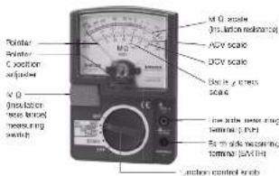
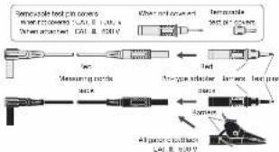
Test Lead(TL-509S)
flowchart
graph LR
    A["Raw material input"] --> B["Add 10%"]
    B --> C["Add 20%"]
    C --> D["Add 30%"]
    D --> E["Add 40%"]
    E --> F["Add 50%"]
    F --> G["Add 60%"]
    G --> H["Add 70%"]
    H --> I["Add 80%"]
    I --> J["Add 90%"]
    J --> K["Add 100%"]
    K --> L["Final Product Output"]
8
[4] Description of Functions
- Function control knob and MQ (insulation resistance) measuring switch by operating these two switches, the functions and ranges can be set as shown below.
| Position of Function Control Knob | N/D Voccurring Satch T1 | Set Range (Function) | |
| DM509S | 500 W/1000 MΩ | AC 600 V | OFF AC 800 V range |
| DM1009S | 1000 W/2000 MΩ | ||
| PDM509S | 500 W/1000 MΩ | ||
| DM509S | 500 W/1000 MΩ | AC 600 V | ON 500 W/1000 MΩ |
| DM1009S | 1000 W/2000 MΩ | 1000 W/2000 MΩ | |
| PDM509S | 500 W/1000 MΩ | 500 W/1000 MΩ | |
| BATTERY CHECK | ON | BATTERY CHECK | |
| DC 60 V | OFF | DC 60 V | |
* The M.O measuring switch is turned on by the following operation. ① ON only when the right end of the lever is pressed with a finger. OFF when the finger is released.
Continuously GN when the left end of the lever is raised. (OFF when it is laid down)
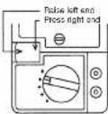
- Meter zero position adjustment
If the meter pointer is not on the = graduation line of the MΩ scale when the function control knob is at OFF, adjust the zero position with a screwdriver.
4
REFERENCE
The MΩ measurement should be performed as quickly as possible to prevent the internal parts from heating. Particularly, when measuring resistance between 0 MΩ to the center of scale, perform each measurement within 20 seconds and leave an equivalent interval to the measuring time before proceeding to the subsequent measurement. The no-load voltage is within 1.25 times the rated measuring voltage.
1) Measuring object
Measurement of insulation resistance (MΩ) of electric equipment and circuits.
2) Rated measuring voltage
| Model | Rated measuring voltage |
| DM509S 500 V | |
| DM1009S | 1000 V |
| PDM509S | 500 V |
S) Selection of a measuring range
Turn the function control knob to (MΩ) / AC 600 V position.
4) Measuring method
① Power off the measuring object.
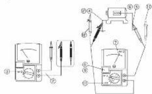
3 Insert the black measuring cord to which the black aligator clip (or black pin-type adapter) is attached into the EARTH (ground) measuring terminal, and the red measuring cord to which the red pin-type adapter is attached into the LINE measuring terminal.
③ Turn the function control knob to a desired rated measuring voltage range.
3) Connect the black alligator clip to the object measured. Usually connect the EARTH (ground) measuring terminal to the grounding side
⑨ Connect the tip of the red pin-type adapter to the other side of the object measured.
△ CAUTION: If the meter deflects in this state, the measuring object is charged. Be sure to remove the voltage prior to measurement.
-8-
How To Use Carrying Case
During measurement, set the case as illustrated and hang it from the neck.
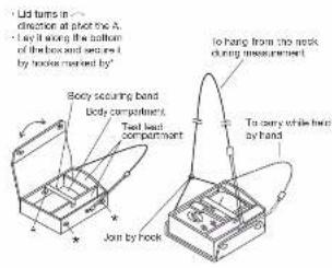
[5] Measuring Method
5.1 Start-up Check
WARNING
- Do not use a damaged tester or test lead.
- Make sure test lead wiring is not broken.
- When testing the continuity of a test load, the measuring terminals are under a high voltage. Be careful of electric shock.
- To prevent electric shock and battery consumption, be sure to turn the MΩ measuring switch and function control knob to OFF after measurement.
42
④ Turn on the MΩ measuring switch.
(See [4] Description of Function)
⑦ Read the indicated value. Use the
① Turn on the M2 measuring switch.
- Discharge the high voltage charged in the measuring object. See 5.4 Discharge Function
(1) First remove the red test pin from the object measured, and then disconnect the black elevator pin.
⑪ Be sure to turn the function control knob to the position of OFF.
CAUTION
- Rated measuring voltage should be selected by a measuring object. For example, 125 V rated measuring voltage should be used for the object, AC input voltage of which is 100 V.
- Remove components such as semi conductors and apparatuses from the circuit of measuring object to avoid damages when withstand of the object is unknown or lower than rated measuring voltage of a resistance insulation tester, especially in case of the objects you measure connected with PCs or computers.
- 3 -
Before starting measurement, check the "appearance", "pointer 0 position" ("), "battery" and "measuring lead" in this order. (The pointer 0 position is the 0 position of the DC 60 V scale or ∞ position of the MO scale.)
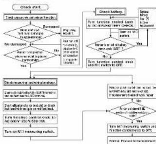
flowchart
graph TD
    A["Check start"] --> B{Check start with battery charging system}
    B -->|Yes| C["Damaged"]
    B -->|No| D{Damaged with battery charging system}
    D -->|Yes| E["Tan function control switch for battery charging"]
    D -->|No| F["Tan function control switch for battery charging"]
    E --> G["Check battery charging"]
    F --> H["Tan function control switch for battery charging"]
    G --> I["Check battery charging"]
    H --> J["Tan function control switch for battery charging"]
    I --> K["Check battery charging"]
    J --> L["Check battery charging"]
    K --> M["Check battery charging"]
    L --> N["Tan function control switch for battery charging"]
    M --> O["Tan function control switch for battery charging"]
    N --> P["Tan function control switch for battery charging"]
    O --> Q["Tan function control switch for battery charging"]
    P --> R["Tan function control switch for battery charging"]
    Q --> S["Tan function control switch for battery charging"]
    R --> T["Tan function control switch for battery charging"]
5.2 How to Check Battery (BATTERY CHECK)
Prior to MΩ (insulation resistance) measurement, be sure to check the battery. A consumed battery will cause not only measurement errors but danger due to erroneous measurement.
For checking methods, refer to 5.1 Start-up Check.
Do not check the battery for more than 5 seconds.
y
5.4 Discharge Function
1) Reason of a need to discharge
For safety, high voltage remaining in capacitive measuring objects such as capacitors and electric wire must be discharged to prevent accidents.
2) Discharging method (This procedure follows the step ⑧ of 5.3-4) ① When the MΩ measurement has been completed, turn off only the MΩ measuring switch with the test pin and the alligator clip connected to the measuring object.
② Then the pointer deflects to the right and its deflection becomes smaller as time passes (indicating the charged charge is being discharged).
② When the pointer steps at zero (wof the MO scale) and discharge has been completed, conduct the steps ⑩ and ⑪ of 5.3-4)
5.5 Measurement of DCV (DC voltage) (Measuring range is the DV 60 V range only)
-
Do not apply a voltage exceeding the maximum rated voltage of 80 VDC.
-
Keep in mind the warnings of 5.8 described earlier.
1) Measuring object
DC voltages of batteries, etc. can be measured. Also, the tester can be used to check the presence of DC voltage prior to MO measurement.
2) Measuring Method 3. not tested result
the: the clock measuring cord of which the block a ignor clip for clock pin-type adoption is attached into the EARTH ground measuring terminal, and the red measuring cord as which the red pin-type oscillator is attached into the LINE measuring terminal.
② Turn the function control knob to DC 60 V. ③ Connect the black alligator clip to the side of the object (circuit) measured,
and connect the tip of the red pin-type adapter to the + side. Good be indicated value on the DCU scale.
⑥ First remove the rad test pin from the object measure, and then
⑥ Turn the function control knob to the position of OFF.
-10-
5.3 Measurement of MΩ (Insulation Resistance)
WARNING
- Never apply a voltage to the measuring terminal when the tester is in the MΩ measuring range.
- Prior to measurement, disconnect the measuring object (circuit) from the power supply.
- Prior to measurement, make sure no voltage is applied to the circuit to measure by the AC 650V range
- During measurement, a high voltage is generated. Do not touch the test pin, clip and measuring object.
- The tester and measured circuit have been charged by high voltage immediately after the measurement. Be careful not to get electric shock.
- There is a possibility of an accident of electric shock. After the measurement, be sure to discharge the high voltage charged in the measuring object. (See 5.4 Discharge Function)
CAUTION
- When the object measured is grounded, usually connect the black EARTH (ground) test load to the grounded side and the red LINE test load to the circuit. (When this connection is used, a measurement value becomes smaller than a value obtained by the reverse connection.)
- To prevent a measuring error, keep the test lead connected to the LINE side out of contact with the measuring object and ground (earth).
- The insulation resistance varies largely depending on temperature and humidity. It is also influenced by a voltage to apply (measuring voltage). Normally as temperature, humidity and voltage increase, the insulation resistance decreases.
√
5.6 Measurement of ACV (AC voltage) (Measuring range is the AC 600 V range only)
WARNING
- Do not apply a voltage exceeding the maximum rated voltage of 800 VAC.
- During measurement, do not operate the function control knob.
-
Do not measure a voltage with the MΩ measuring switch being pressed or eased.
-
When the circuit to measure has a breeder, measure the voltage on the secondary side (load side).
-
To prevent electric shock, do not touch the metal part of the pin plug and clip.
CAUTION
AC voltages of waveforms other than sinusoidal waveforms and frequencies other than _1 to fill Hz will cause an indication over
In the case of the first time, the 15th class A2 was called in the first class.
1) Measuring object
Sinucleolar AC voltages (ACV)
such as lighting line voltages
can be measured.
2) Measuring method
(-) Insert the black measuring cord to which the back oscillator of the rear back on-type adapter is attached into the EARTH (ground measuring terminal, and the red measuring cord to which the rear pin-type scooter is attached into the LINE measuring terminal.
② Turn the function control knob to AC 600 V.
③ Connect the black alligator clip to the earth (grounding) side of
the object measured, and connect the tip of the red pin-type
④. Read the indicated value on the ACV scale.
② First remove the red test pin from the object measured, and
then disconnect the black aligator clip from it.
① Turn the function control knob to the position of OFF.
- 11 -
[6] After-Sales Service
6-1 Warranty and Provision
Sanwa offers comprehensive warranty services to its end-users and to its product resellers. Under Sanwa's general warranty policy, each instrument is warranted to be free from defects in workmanship or material under normal use for the period of one (1) year from the date of purchase.
This warranty policy is valid within the country of purchase only, and applied only to the product purchased from Senwa authorized agent or distributor.
Sanwa reserves the right to inspect all warranty claims to determine the extent to which the warranty policy shall apply. This warranty shall not apply to test leads, disposables batteries, or any product or parts, which have been subject to one of the following causes:
-
A failure due to improper handling or use that deviates from the instruction manual.
-
A failure due to inadequate repair or modification by people other than Sarwa service personnel.
-
A failure due to causes not attributable to this product such as fire, flood and other natural disaster.
-
Non-operation due to a discharges battery
-
A failure or damage due to transportation, relocation or dropping after the purchase.
6-2 Repair
Customers are asked to provide the following information when requesting services:
-
Customer name, address, and contact information
-
Description of problem
-
Description of product configuration
-
Model Number
-
Product Serial Number
-
Proof of Date-of-Purchase
-
Where you purchased the product
1) Prior to requesting repair, please check the following:
Capacity of the battery, polarity of installation and discontinuity of the test leads.
2) Repair during the warranty period
The isled meter will be repaired in accordance with the conditions stipulated in 6-1 Warranty and Provision.
3) Repair after the warranty period has expired:
In some cases, repair and transportation cost may become higher than the price of the product. Please contact Sarwa authorized agent / service provider in advance.
The minimum retention period of service functional parts is 6 years after the discontinuation of manufacture. This retention period is the repair warranty period. Please note, however, if such functional parts become unavailable for reasons of discontinuation of manufacture, etc., the retention period may become shorter accordingly.
6). The retention period may be coming shorter accord. 4) Precautions when sending the product to be repaired
To ensure the safety of the product during transportation, places the product in a box that is larger than the product 5 times or more in volume and till cushion materials fully and then clearly mark "Repair Product Enclosed" on the box surface. The cost of sending and returning the product shall be borne by the customer.
6-3 SANWA web site
http://www.sanwa-meter.co.jp
E-mail: exp_sales@sanwa-meter.co.jp
[7] Battery Replacement
① Remove two battery lid
securing screws.
(2) Replace the consumed battery that is connected to
Battery there is connected to the snap terminal with a
① Set the battery in the
original place and secure the
battery lid with screws. (PLF22)
Be sure to turn the function control knob to the position of OFF prior to replacing the battery.
Be sure to use the alkaline battery 6LP01(6LF22) (8 V).
2
[Non-Text]
[8] Specifications
8.1 Measurement Range and Accuracy
Accuracyassurance : 23±5 ℃ 75 % RH max.
No condensation
Altitude: Horizontal ±5°. External magnetic field. Not present.
Battery voltage: W power is effective.
| Model | DM509S | DM1009S | PDM509S |
| M3 Resistance Range | Rated measuring voltageKneasing range | Lampenerat, 1st harmonic measuring scaleFull tunnel, 2nd effective measuring scale | |
| 500 V~1000 MΩ | 1000 V~2000 KΩ | 600 V~1000 MΩ | |
| ACV range | 0-600 V | ||
| DCV range | 0-60 V | ||
| Accuracy | • MΩrange1st effective measurement range: ±5 % of reading2nd effective measurement range: ±10 % of reading0,000 scale: ±0.7 % of scale lengthNo load voltage: ±2% of rate reading voltageRotor current: ±1-12 mAShort circuit current: max 2.9 mA | ||
| • ACV range (50/60 Hz sine wave): ±5 % of full scale | |||
| • DCV range | ±5 % of full scale | ||
| Operating instrument unimony | Within ±30 % (Maximum value tolerated by IEC standards)Variation-causing factors [E-I: Arithmetic, E2: Supply voltage, E3: Temperature] | ||
*Factory-preinstalled battery
A battery for monitoring is preinstalled before shipping, therefore it may run down sooner than the battery life specified in the instruction manual. The "battery for monitoring" is a battery to inspect the functions and specifications of the product.
-14-
8.2 General Specifications
AC rectifying method : Half-wave rectification
(Mean value indication rms value converted)
Meter specification : Inter-pots type tan-band system, 24 μA PD1609348 μN
Battery consumption : Checked by BATTERY CHECK range.
Alveleterrestundlage: 23=5°C, 75% RH max., no condensation. Service temperature: 0-43°C, 80% RH max., no condensation.
Storage semiconductor: 10-50 W, 70 W, 480 MHz. No consideration.
Service ambient condition: Altitude 2000 mm max., environmental pollution II.
Power supply: Layer built type alkaline battery 6LRF1(3LF22) x 1.9 V
Max. power consumption: 2.0 W=2.8 W at MΩ range
Battery life: When the lower limit measurement resistance value then can maintain the rated output voltage is measured and if one cycle for the measurement is defined as ON for 5 seconds and OFF for 25 seconds, the battery life is 500 cycles.
Degree of IP : IP20
EMC Directs: RHS Directs : IEC61326 (EMC), EN50581(ROHS)
Safety : IEC61010-1 : IEC61010-2-030 CAT.III 600 V*
- Measurement Category II: Line from the primary set or branch of equipment which directly ICAI. III: takes in electricity from and distribution based to the reopazable.
Year of manufacture: The first two digits of the total number on
Roll of Manufacture. The first two digits of the serial number for the bottom of this product indicate the last two digits of the year.
Size and Mass
Accessories : Test lead TL-508S, 1 set
Image of no manual 1. Campan care C-098S
EC81010-2-033, EC81010-031
小COUTION
- The paper and the case are not resistant to volatile solvent and must not be cleaned with thinner or alcohol.
For cleaning, use dry, soft cloth and wipe it lightly
- The panel and the case are not resistant to heat. Do not place the
instrument near host-generating devices (such as a soldering iron).
- Do not store the instrument in a place where it may be subjected to substitution as follows:
to vibration of from where it may fail.
- For storing the instrument, avoid hot, cold or humid pieces or
places under direct sunlight or where compensation is anticipated.
- 15
12
23
[Non-Text]
Brand : Sanwa
Model : DM509S
Category : Measurement