DCL11R - Measurement Sanwa - Free user manual and instructions
Find the device manual for free DCL11R Sanwa in PDF.


| Product Type | Digital Clamp Meter |
| Brand | Sanwa |
| Model | DCL11R |
| Category | Measurement |
| Display | LCD, 4000 counts |
| AC Current Range | 400A / 1000A |
| AC/DC Voltage Range | 400V / 600V |
| Resistance Range | 400Ω / 40MΩ |
| Jaw Opening | Approx. 30 mm |
| Safety Rating | CAT III 600V |
| Power Supply | 2 x AAA batteries |
| Auto Power Off | Yes, after 15 minutes |
| Data Hold | Yes |
| Dimensions | 230 x 70 x 30 mm |
| Weight | Approx. 200 g (including batteries) |
| Operating Temperature | 0°C to 40°C |
| Storage Temperature | -10°C to 60°C |
| Included Accessories | Test leads, carrying case, batteries |
| Maintenance | Clean with a dry, soft cloth. Do not use solvents. |
Frequently Asked Questions - DCL11R Sanwa
User questions about DCL11R Sanwa
0 question about this device. Answer the ones you know or ask your own.
Ask a new question about this device
Download the instructions for your Measurement in PDF format for free! Find your manual DCL11R - Sanwa and take your electronic device back in hand. On this page are published all the documents necessary for the use of your device. DCL11R by Sanwa.
USER MANUAL DCL11R Sanwa
DIGITAL CLAMP METER INSTRUCTION MANUAL
SANWA ELECTRIC INSTRUMENT CO., LTD.
Dempa Bldg., 4-4 Sotokanda 2-Chome
Chiyoda-ku, Tokyo, Japan


PRINTED WITH
SOYINK
This manual employs soy ink.
01-1507 2040 6011
[1] SAFETY PRECAUTIONS
Before use, read the following safety precautions.
This instruction manual explains how to safely use your new DCL11R digital clamp meter. Before use, please read this manual thoroughly. After reading it, keep it together with the product so you can refer to it when necessary. If this product is not used as specified in this manual, its protection function may be compromised.
To avoid accidental burns or electric shock, always follow any instructions with "△WARNING" or "△CAUTION" headings.
1-1 Explanation of Warning Symbols
The meanings of the symbols used in this manual and on the product are explained below.
⚠️ : Very important instructions for safe use
- Warning messages are intended to prevent accidents to operating personnel such as burn and electric shock.
- Caution messages are intended to prevent damage to the instrument.
The meanings of the symbols used exclusively on the product are explained below.
⚠️: Symbol requesting reference to the instruction manual before use
4: Potential of connection to a power line in live status
☐ : Double in sulation or reinforced insulation
○ : Power switch : Backlight ✪
1-2 Warning Instructions for Safe Use
WARNING
To avoid physical injury such as burns or electric shock, be sure to observe the following instructions when using this instrument.
- This instrument is a digital clamp meter for low voltages. It should be used on power lines with a voltage to ground of 300 Vrms or less.
- Pay special attention when measuring voltages of AC 33 Vrms (46.7 V peak) or DC 70 V or more to avoid injury. Also use insulating protective equipment as required.
- Never use the instrument on power lines that exceed the maximum rated input current (see 1-3).
- Do not use the instrument if the main unit is damaged or broken.
- Do not use the instrument with the case or battery compartment cover removed.
- Do not hold the measurement clip at any point beyond the barrier.
- Do not use the instrument when it or your hand is wet.
- Do not attempt to repair or modify the instrument except to replace the batteries.
- Be sure to check the instrument before each use and inspect it at least once a year.
- Always use the instrument indoors.
- To avoid compromising the protection function of this instrument, do not use it in any way other than instructed in this manual.
* Voltage to ground of 300 Vrms or less: When the Y-connection voltage is 415 V, the voltage to ground is equal to 415 / 3 ÷ 240V .
1-3 Overload Protection Input Values
| Input Max. rated input current Max. overload protection input | |
| Clamp sensor | AC 320 A AC 350 A |
[2] APPLICATIONS AND FEATURES
2-1 Application
This instrument is an AC clamp meter with RMS response that allows you to measure the current range specified in IEC 61010-1 CAT. III 300 V. It is suitable for measuring the current of low-voltage power lines and electrical appliances.
2-2 Features
- Safety design that complies with IEC61010-1 CAT. III 300 V
- Compact pocket size
• True RMS conversion
• Auto power OFF (approx. 15 min.) (Disabling also possible) - Backlight
Measurement Category (Overvoltage Category)
Equipment of CAT II :
Primary cable runs of power-consuming equipment from a wall socket.
Equipment of CAT III :
Primary cable runs of equipment directly connected to a distribution board and cable runs from a distribution board to wall sockets.
Equipment of CAT IV: Cable runs from an incoming line to a distribution board.
[3] NAME OF COMPONENT UNITS
3-1 Main unit
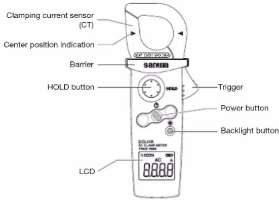
3-2 Display
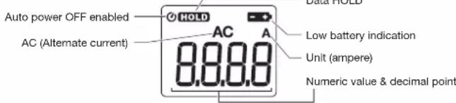
[4] DESCRIPTION OF FUNCTIONS
4-1 Power button: button
Press the button to switch the power on and off.
4-2 Auto power OFF function
The instrument incorporates the auto power OFF function that turns the instrument OFF in about 15 minutes after the last operation. This function can be disabled by switching the instrument ON while holding the ⚙button. The Ⓧ indicator on the display panel is extinguished when the auto power OFF function is disabled.
4-3 Low battery indication
The indicator lights on the display when the batteries have discharged down to a supply voltage of about 2.3 V or less. Replace the batteries when this indicator lights up.
4-4 Data hold function: Houlton
Press the HOLD button. The HOLD indicator lights on the display and the value displayed at that time is held and will not change even if the measurement data varies. Pressing the button against extinguishes the HOLD indicator and the measurement data is no longer held.
4-5 Backlight function: ✿ button
Press this button to light the backlight of the display. Pressing the button again extinguishes the backlight. The backlight is also extinguished automatically in about 10 seconds after it is lit.
[5] MEASURING PROCEDURE
WARNING
- Do not apply an input voltage exceeding the maximum rated current.
- During measurement, do not hold the measurement clip at any point beyond the barrier.
5-1 Start-up inspection
Perform the following pre-operational check for safety.
- Check the external appearance. Check that the main unit is free of abnormality or damage due to dropping, etc.
- Check that the indicator is not lit. If it is lit, replace the batteries with new ones.
- Make sure your hands and the instrument are not wet.
*If nothing is displayed on the LCD, the batteries might have been totally discharged.
5-2 Measuring the AC current (ACA measurement)
CAUTION
- To improve the measuring accuracy, position the conductor at the center of the clamp sensor.
- Always clamp only one wire at a time. Accurate measurement is impossible if two or more wires, a cable with multiple conductors or a parallel cord is clamped.
- Accurate measurement is impossible if the clamp sensor is not closed completely.
- Accurate measurement is sometimes impossible near a source of strong magnetic field such as a transformer or high-current line, near a source of electromagnetic waves such as radio equipment or near a charged object.
- The CT may generate an oscillating sound when a high current is applied. This is not malfunction.
① Set the Power switch to ON.
② Open the clamp sensor, catch the single wire to be measured and close the clamp sensor completely.
③ Read the measurement value.
Correct O
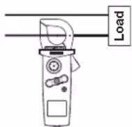
Clamping single conductor on the center of clamp sensor.
Incorrect X
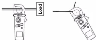
natural_image
Two identical line drawings of a handheld device with a labeled 'Load' indicator (no text or symbols on the devices themselves)Clamping multiple conductors. Force applied to the tip of clamp sensor.
[6] MAINTENANCE
WARNING
- This section is very important for safety. Read and understand the following instructions fully and maintain your instrument properly.
- To maintain safety and accuracy, calibrate and inspect the instrument at least every year.
6-1 Maintenance and Inspection
Before use, check the instrument to confirm that there is no abnormality and that the CT can be opened and closed smoothly. If anything is abnormal, do not use the instrument and return it to your authorized Sanwa agent or distributor for repair.
6-2 Calibration
For more information, please contact Sanwa's authorized agent / distribute service provider, listed in our website. See section 7-3.
6-3 Cleaning and Storage
CAUTION
- The panel and case are not resistant to volatile solvent and must not be cleaned with thinner or alcohol. If the instrument gets dirty, wipe with a soft cloth moistened with a small amount of water.
- The panel and case are not resistant to heat. Do not place the instrument near heat-generating devices (such as a soldering iron).
- Do not store the instrument anywhere it may be subject to vibrations or could fall.
- When storing the instrument, avoid hot, cold or humid locations, locations exposed to direct sunlight, or locations where condensation is anticipated.
- When the instrument is not going to be used for an extended time, be sure to remove the batteries.
6-4 Battery replacement
- Batteries shipped with the instrument
The batteries loaded at the factory are monitor batteries, so their service life may be shorter than that of brand-new batteries. Monitor batteries are a type of battery used to check the functions and performance of a product.
WARNING
- To avoid electric shock, do not remove the battery compartment cover while an input is applied to the clamp sensor or the instrument is measuring something.
- Make sure that the instrument is set to OFF before replacing the batteries.
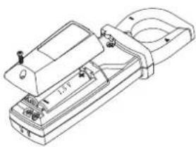
natural_image
Technical line drawing of a mechanical device with no visible text or symbols① Using a Phillips screwdriver, remove the fixing screw (x 1) from the battery compartment cover.
② Remove the battery compartment cover.
③ Replace both of the batteries in the battery holder with new ones by observing the correct polarity.
④ Place the battery compartment cover and tighten the fixing screw in the original position.
[7] AFTER-SALE SERVICE
7-1 Warranty and provision
Sanwa offers comprehensive warranty services to its end-users and to its product resellers. Under Sanwa's general warranty policy, each instrument is warranted to be free from defects in workmanship or material under normal use for the period of one (1) year from the date of purchase.
This warranty policy is valid within the country of purchase only, and applied only to the product purchased from Sanwa authorized agent or distributor.
Sanwa reserves the right to inspect all warranty claims to determine the extent to which the warranty policy shall apply. This warranty shall not apply to disposables batteries, or any product or parts, which have been subject to one of the following causes:
- A failure due to improper handling or use that deviates from the instruction manual.
- A failure due to inadequate repair or modification by people other than Sanwa service personnel.
- A failure due to causes not attributable to this product such as fire, flood and other natural disaster.
- Non-operation due to a discharged battery.
- A failure or damage due to transportation, relocation or dropping after the purchase.
7-2 Repair
Customers are asked to provide the following information when requesting services:
- Customer name, address, and contact information
- Description of the problem
- Description of the product configuration
- Model Number
- Product Serial Number
- Proof of Date-of-Purchase
- Where you purchased the product
Please contact Sanwa authorized agent / distributor / service provider, listed in our website, in your country with above information. An instrument sent to Sanwa / agent / distributor without above information will be returned to the customer.
Note:
1) Prior to requesting repair, please check the following:
Capacity of the built-in battery, polarity of installation and discontinuity of the test leads.
2) Repair during the warranty period:
The failed instrument will be repaired in accordance with the conditions stipulated in 7-1 Warranty and provision.
3) Repair after the warranty period has expired:
- If it is expected that servicing can restore the original functioning of the product, we will service it for a price upon request of the user.
- The service charge or transport freight could sometimes become higher than the product price. Please consult us before asking for servicing.
- The minimum retention period of the servicing performance parts of this product is six (6) years after the discontinuation of production. This period is equal to the servicing available period. However, the retention period of a part may be reduced if it becomes unavailable due to discontinuation of production of the part manufacturer, etc.
4) Precautions when sending the product to be repaired:
To ensure the safety of the product during transportation, place the product in a box that is larger than the product 5 times or more in volume and fill cushion materials fully and then clearly mark "Repair Product Enclosed" on the box surface. The cost of sending and returning the product shall be borne by the customer.
7-3 SANWA web site
http://www.sanwa-meter.co.jp
E-mail: exp_sales@sanwa-meter.co.jp
[8] SPECIFICATIONS
8-1 General Specifications
| Operation method Δ- | Σ method |
| AC detection method True RMS method (AC coupling) | |
| Display 6000 count | |
| Sampling rate Approx. 2 times/sec | |
| Overload display “OL” on the numeric display | |
| Range selection Auto range | |
| Low battery indication | When the batteries are discharged down to 2.3 V or less, the indicator lights on the display. |
| Current measurement method / aperture diameter | Clamping current sensor (CT) / Max. approx. dia. φ 22 mm |
| Operation environment | Altitude max. 2000 m, indoor use, environmental pollution degree II. |
| Operating temperature/ humidity | Temperature 5 to 40 °C, Relative humidity max. 80 % RH at 5-31 °C and decreases linearly through 80 % RH to 50 % RH at 31-40 °C (without condensation) |
| Storage temperature/ humidity | -10 to 40 °C: Max. 80 % RH (without condensation) 40 to 50 °C: Max. 70 % RH (without condensation) |
| Power supply “AAA”-size alkaline battery LR03 x 2 | |
| Auto power OFF Power | off in approx. 15 min. after last operation |
| Power consumption / Battery life | Approx. 1.9 mA / Approx. 500 hours (backlight extinguished) |
| Dimensions and mass | 145 (H) x 54 (W) x 31 (D) mm, approx. 120 g (including batteries) |
| Safety standards | IEC61010-1, IEC61010-2-030 CAT. III 300 V, IEC61010-2-32 |
| EMC directive IEC61326-1 | |
| Accessories | Instruction manual, carrying pouch (C-DCL10) |
8-2 Measuring ranges and accuracies
Accuracy-guaranteed temperature/humidity range: 23 ±5 °C, max. 80 % RH (without condensation).
rdg: Reading dgt: digits (lowest digit)
Accuracy-guaranteed range: 1 % to 100 % of measurement range
Crest factor CF: Full-scale CF < 1.6, half scale CF < 3.2
ACA measurement RMS response, AC coupling (sine wave alternate current)
| Range | Resolution | Accuracy: 50/60 Hz | Accuracy: 45-400 Hz |
| 60.00 A | 0.01 A | ± (2.0 %rdg + 5 dgt) | ± (3.0 %rdg + 10 dgt) |
| 300.0 A | 0.1 A |
Accuracy measurement method
(Example) ACA measurement
Reading: 10.00 A
Range accuracy: 60.00 A range = ±(2 %rdg + 5 dgt)
Error: ±(10.00 A × 2.0 % + 0.01 A + 5) = ±0.25 A
True value: 10.00 A ±0.25 A (in the range from 9.75 to 10.25 A)
* 3 dgt in the 60.00 A range is equivalent to 0.03 A.
* 3 dgt in the 300.00 A range is equivalent to 0.3 A.
Specifications and external appearance of the product described above may be revised or modified without prior notice.
- DIGITAL CLAMP METER INSTRUCTION MANUAL
- SANWA ELECTRIC INSTRUMENT CO., LTD.
- [1] SAFETY PRECAUTIONS
- 1-1 Explanation of Warning Symbols
- 1-2 Warning Instructions for Safe Use
- WARNING
- 1-3 Overload Protection Input Values
- [2] APPLICATIONS AND FEATURES
- 2-1 Application
- 2-2 Features
- Measurement Category (Overvoltage Category)
- [3] NAME OF COMPONENT UNITS
- 3-1 Main unit
- [4] DESCRIPTION OF FUNCTIONS
- [5] MEASURING PROCEDURE
- 5-1 Start-up inspection
- 5-2 Measuring the AC current (ACA measurement)
- CAUTION
- [6] MAINTENANCE
- 6-1 Maintenance and Inspection
- 6-2 Calibration
- 6-3 Cleaning and Storage
- 6-4 Battery replacement
- - Batteries shipped with the instrument
- [7] AFTER-SALE SERVICE
- 7-1 Warranty and provision
- 7-2 Repair
- Note:
- 7-3 SANWA web site
- [8] SPECIFICATIONS
- 8-2 Measuring ranges and accuracies
- Accuracy measurement method
Brand : Sanwa
Model : DCL11R
Category : Measurement