
XT-40 - Elliptical bike LifeSpan - Free user manual and instructions
Find the device manual for free XT-40 LifeSpan in PDF.


| Product Type | Elliptical Trainer (Elliptical Bike) |
| Model | XT-40 |
| Brand | LifeSpan |
| Dimensions (L x W x H) | 68 x 24 x 62 inches (173 x 61 x 157 cm) |
| Weight | 165 lbs (75 kg) |
| Maximum User Weight | 350 lbs (159 kg) |
| Power Source | Self-powered (generator) or AC adapter (input: 100-240V, 50/60Hz) |
| Display Type | LCD with backlit, 5 x 3 inches |
| Display Feedback | Time, distance, calories, speed, RPM, heart rate, resistance level |
| Resistance System | Electromagnetic, 20 levels |
| Number of Programs | 12 preset programs + 2 user-defined + heart rate control |
| Heart Rate Monitoring | Contact grips and telemetry (chest strap compatible) |
| Stride Length | 20 inches (51 cm) |
| Pedal Spacing | 4 inches (10 cm) - low Q-factor |
| Warranty | Frame: lifetime; parts: 3 years; labor: 1 year |
| Assembly Required | Yes, basic assembly with included tools (approx. 30 minutes) |
| Maintenance | Regular cleaning, tighten bolts monthly, lubricate sliding rails |
| Safety Features | Emergency stop button, leveling feet, stable frame design |
| Connectivity | USB charging port (for devices up to 2A), Bluetooth for app connectivity |
| Additional Features | Transport wheels, water bottle holder, tablet holder |
| Certifications | EN957, FCC, CSA |
Frequently Asked Questions - XT-40 LifeSpan
User questions about XT-40 LifeSpan
0 question about this device. Answer the ones you know or ask your own.
Ask a new question about this device
Download the instructions for your Elliptical bike in PDF format for free! Find your manual XT-40 - LifeSpan and take your electronic device back in hand. On this page are published all the documents necessary for the use of your device. XT-40 by LifeSpan.
USER MANUAL XT-40 LifeSpan
XT-40 Ascender Incline Cross Trainer
USER MANUAL

Read all instructions carefully before using this product. Retain this owner's manual for future reference.

IMPORTANT
All nuts and bolts are to be checked and tightened on a regular basis. This includes pedals and other moving parts. Failure to do so may cause damage to your threads and void your warranty.
NOTE:
This manual should not be used to guide your purchasing decision. Your product, and the contents inside its carton, may vary from what is listed in this manual. This manual may also be subject to updates or changes. Updated manuals are available through our website at www.lifespanfitness.com.au
TABLE OF CONTENTS
I. Important Safety Instructions 03
II. Care Instructions 04
III. Exploded Diagram 06
IV. Parts List 07
V. Assembly Instructions 11
VI. Computer Operation ......15
VII. Exercise Guide 24
VIII. Warranty 26
IX. Hand Pulse Technology 27
I. IMPORTANT SAFETY INSTRUCTIONS

WARNING: Read all instructions before using this machine.
It is important your machine receives regular maintenance to prolong its useful life. Failing to regularly maintain your machine may void your warranty.
Please keep this manual with you at all times.
- It is important to read this entire manual before assembling and using the equipment. Safe and effective use can only be achieved if the equipment is assembled, maintained and used properly.
Please note: It is your responsibility to ensure that all users of the equipment are informed of all warnings and precautions.
- Before starting any exercise program you should consult your doctor to determine if you have any medical or physical conditions that could put your health and safety at risk, or prevent you from using the equipment properly. Your doctor's advice is essential if you are taking medication that affects your heart rate, blood pressure or cholesterol level.
- Be aware of your body's signals. Incorrect or excessive exercise can damage your health. Stop exercising if you experience any of the following symptoms: pain, tightness in your chest, irregular heartbeat, and extreme shortness of breath, lightheadedness, dizziness or feelings of nausea. If you do experience any of these symptoms, you should consult your doctor before continuing with your exercise program.
- Keep children and pets away from the equipment. This equipment is designed for adult use only.
- Use the equipment on a solid, flat level surface with a protective cover for your floor or carpet. To ensure safety, the equipment should have at least 2 meters of free space around it.
- Before using the equipment, check that the nuts and bolts are securely tightened. If you hear any unusual noises coming from the equipment during use and assembly, stop immediately. Do not use the equipment until the problem has been rectified.
- Wear suitable clothing while using the equipment. Avoid wearing loose clothing that may get caught in the equipment or that may restrict or prevent movement.
• This equipment is designed for indoor and family use only
- Care must be taken when lifting or moving the equipment so as not to injure your back.
• Always keep this instruction manual and assembly tools at hand for reference.
- The equipment is not suitable for therapeutic use.
- The pulse or heart rate sensors are not medical devices. Various factors, including the user's movement, may affect the accuracy of heart rate readings. The pulse sensors are intended only as exercise aids in determining heart rate trends in general.
II. CARE INSTRUCTIONS
- Lubricate moving joints with grease after periods of usage.
- Be careful not to damage plastic or metal parts of the machine with heavy or sharp objects.
- The machine can be kept clean by wiping it down using dry cloth.
- All nuts and bolts are to be checked and tightened on a regular basis. This includes pedals and other moving parts. Failure to do so may cause damage to your thread and void your warranty.
III. EXPLODED DIAGRAM
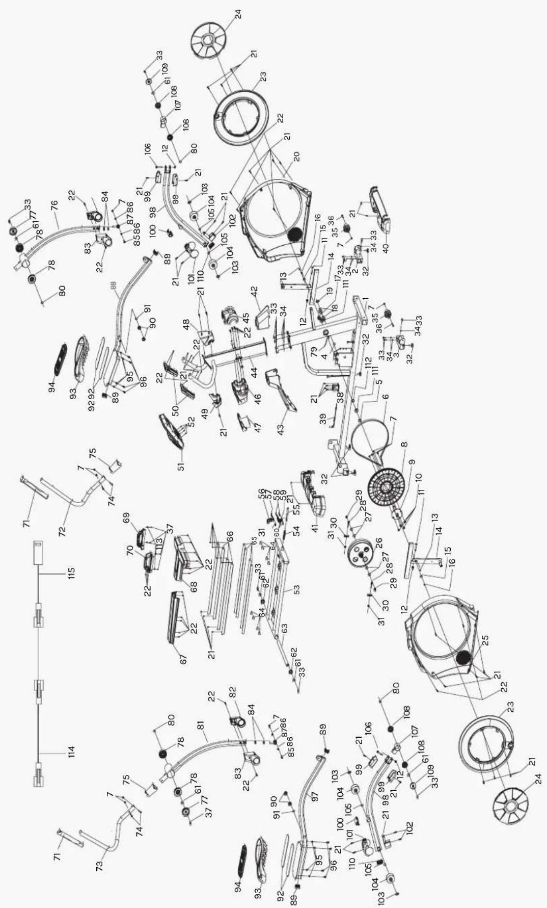
IV. PARTS LIST
NO. Name Specs Qty
| 1 | Main Frame Welding 1 | ||
| 2 | Left front foot tube connection Welding 1 | ||
| 3 | Right front foot tube connection Welding 1 | ||
| 4 | Waveform gasket 1 | ø10 | 1 |
| 5 | Short crank sleeve | ø25*ø20.5*9 | 1 |
| 6 | Belt | 545J6 | 1 |
| 7 | Nut | GB/T 889.1-2000 M8 | 12 |
| 8 | Belt Wheel | ø380*22.2 | 1 |
| 9 | Straight Mandrel Assembly | ø20*170 | 1 |
| 10 | Bolt 1 | GB/T 70.2-2000 M8*16 | 4 |
| 11 | Bolt 2 | GB/T 5780-2000 M10*55 | 2 |
| 12 | Nut | GB/T 889.1-2000 M10 | 4 |
| 13 | Small Square Tube | 15*6*6 | 2 |
| 14 | Cross Assembly Welding 2 | ||
| 15 | Middle Gasket | ø25*ø6.2*1.5 | 2 |
| 16 | Bolt 3 | GB/T 5780-2000 M6*20 | 2 |
| 17 | Fixing Nut | M20*1.0 | 1 |
| 18 | Bearing | 6300ZZ | 2 |
| 19 | Outer Spring GB/T 959.1-1986 10 | 1 | |
| 20 | Left Chain Cover 826*100*737 | 1 | |
| 21 | Screw 1 | GB/T 845-1985 ST4.2*19 | 44 |
| 22 | Screw 2 | GB/T 845-1985 ST4.2*13 | 38 |
| 23 | Rotary Table | ø568.9*35.8 | 2 |
| 24 | Rotary Table Cover | ø364*20 | 2 |
| 25 | Right Chain Cover | 826*101*737 | 1 |
| 26 | Flywheel | ø260*121 | 1 |
| 27 | Flat Washer | GB/T95-2002 10 | 4 |
| 28 | Fixing Bolt | M6*58 | 2 |
NO. Name Specs Qty
| 29 | Fixing Nut 2 GB/T 6177.2-2000 M10*1.0 | 2 | |
| 30 | Pull out the fixed piece | ø3 | 2 |
| 31 | Nut GB/T 889.1-2000 M6 | 3 | |
| 32 | Stopper | ø38*47*M8 | 5 |
| 33 | Bolt 1 | GB/T 70.2-2000 M8*20 | 18 |
| 34 | Washer | GB/T 859-1987 8 | 10 |
| 35 | Carrying Wheel | ø63.5*52 | 2 |
| 36 | Bolt 2 | GB/T 5780-2000 M8*70 | 2 |
| 37 | Screw 1 | GB/T 5780-2000 M4*10 | 6 |
| 38 | Wire Control Motor | P=150 | 1 |
| 39 | Motor Cable | P=115 | 1 |
| 40 | Non-Pressure Head | 657.9*170*67.8 | 1 |
| 41 | Tail Cover | 656.7*181.8*123.6 | 1 |
| 42 | Chain Cover Front Cover | 183*120.4*150.5 | 1 |
| 43 | Chain Cover Rear Cover | 445*135*260 | 1 |
| 44 | Instrument Tube Assembly | Welding | 1 |
| 45 | Front Lid of Kettle | 198*145*71.5 | 1 |
| 46 | Middle Lid of Kettle | 198*181*145 | 1 |
| 47 | Top Cover of Kettle 143*130*97 | 1 | |
| 48 | Instrument Front Cover 168*142*77 | 1 | |
| 49 | Instrument Rear Cover 165*100*75 | 1 | |
| 50 | Pulse Glove 221*49*42 | 2 | |
| 51 | Computer JS-10331 | 1 | |
| 52 | Bolt 3 | GB/T 5780-2000 M5*10 | 4 |
| 53 | Guide rail Bracket Assembly | Welding | 1 |
| 54 | Adjusting Spring | ø12.5*90 | 1 |
| 55 | Adjusting Bolt | ø14*128 | 1 |
| 56 | Button | 73.4*31.4*27.5 | 1 |
| 57 | Bolt 1 | GB/T 70.2-2000 M6*40 | 1 |
| 58 | Screw 4 | GB/T 5780-2000 M4*30 | 2 |
| 59 | Button Connection Block | 54*41*23.5 | 1 |
NO. Name Specs Qty
| 60 | Nut | GB/T 889.1-2000 M4 | 2 |
| 61 | Large Gasket | 28* 8.2*2 | 8 |
| 62 | Rotating Shaft Sleeve 38*15 | 2 | |
| 63 | Rear Rotating Shaft | 25*430 | 1 |
| 64 | Protective Mat | 43*12* 1.5 | 8 |
| 65 | EVA | 700*52* 1.0 | 4 |
| 66 | Aluminum Guide Rail | 38*19*730 | 4 |
| 67 | Guide Rail Middle Cover | 481*131*7*58 | 1 |
| 68 | Guide Rail Front Cover | 461.2*305.5*70 | 1 |
| 69 | Left Adjusting Handle | 201.6*85.4*57.2 | 1 |
| 70 | Right Adjusting Handle | 201.7*85.4*49 | 1 |
| 71 | Shaving Handle Sleeve | 330*67*41.8 | 2 |
| 72 | Left Hand Crank Tube | 32*2.0 | 1 |
| 73 | Right Hand Crank Tube | 32*2.0 | 1 |
| 74 | Bolt 2 | GB/T 5780-2000 M8*42 | 4 |
| 75 | Hand Crank Tube Cover | 68.2*117 | 2 |
| 76 | Left Hand Crank Tube Assembly | Welding | 1 |
| 77 | Rocker End Cap | 76*6.5 | 2 |
| 78 | Hand Crank Bushing 76*17.5 | 4 | |
| 79 | Sensor L=150 | 1 | |
| 80 | Rotating Gasket 25* 20.1*10 | 4 | |
| 81 | Right Hand Crank Tube Assembly Welding | 1 | |
| 82 | Left Joint Cover 181*107*51.5 | 2 | |
| 83 | Right Joint Cover | 181*107*51.5 | 2 |
| 84 | Nut | GB/T 41-2000 M12*1.75 H=9 | 4 |
| 85 | Bolt 5 | 10*M8*32 | 2 |
| 86 | Universal Joint Bushing | 16*6 | 4 |
| 87 | Universal Joint | M12*56 | 2 |
| 88 | Left Pedal Tube Assembly | Welding | 1 |
| 89 | Elliptic Plug | 50*25*2.0 | 4 |
| 90 | Foot Tube Sleeve | 32* 19*14 | 4 |
NO. Name Specs Qty
| 91 | Waveform Gasket ø19 2 | ||
| 92 | EVA | 280*50* ø3.0 | 4 |
| 93 | Pedal 434*220*102 | 2 | |
| 94 | Foot Pedal Pad | 378.1*174.9 ø13 | 2 |
| 95 | Flat Washer | GB/T 95-2002 6 | 8 |
| 96 | Bolt 4 | GB/T 70.2-2000 M6*15 | 8 |
| 97 | Right Pedal Tube Assembly | Welding | 1 |
| 98 | Roller Support Tube Assembly | Welding | 2 |
| 99 | Rotary Shaft Cover | 104.6*50*43 | 4 |
| 100 | Foot Tube Shaft Cover | 88*62*32 | 2 |
| 101 | Roller Cover | 146.7*131.8*89.7 | 2 |
| 102 | Roller Spacer | 122*62*44 | 2 |
| 103 | Outer Spring | GB/T 959.1-1986 15 | 4 |
| 104 | Roller ø79*37 4 | ||
| 105 | Waveform Gasket ø16 4 | ||
| 106 | Bolt 4 | GB/T 70.2-2000 M6*15 | 2 |
| 107 | Rocker Arm Connecting Pipe Assembly | Welding | 2 |
| 108 | Roller Bushing ø56*17.5 4 | ||
| 109 | Rotary Disk End Cover | ø57*6.6 2 | |
| 110 | Elliptic Plug 60*30*2.0 | 2 | |
| 111 | Bearing 6004ZZ | 10 | |
| 112 | Flywheel Inner Sleeve ø25*ø20.5*61.1 | 1 | |
| 113 | Flat Washer GB/T 95-2002 4 | 4 | |
| 114 | Upper Segment Line | L=750 | 1 |
| 115 | Lower Segment Line | L=850 | 1 |
| 116 | Power Adapter | 1 |
V. ASSEMBLY INSTRUCTIONS
A. Before assembling make sure that you will have enough space around the item.
B. Use the supplied tools for assembly.
C. Before assembling please check whether all needed parts are available. Above of this instruction sheet you will find an explosion drawing with all single parts (marked with numbers) which this item consists of. Some parts may be pre-installed on machine.
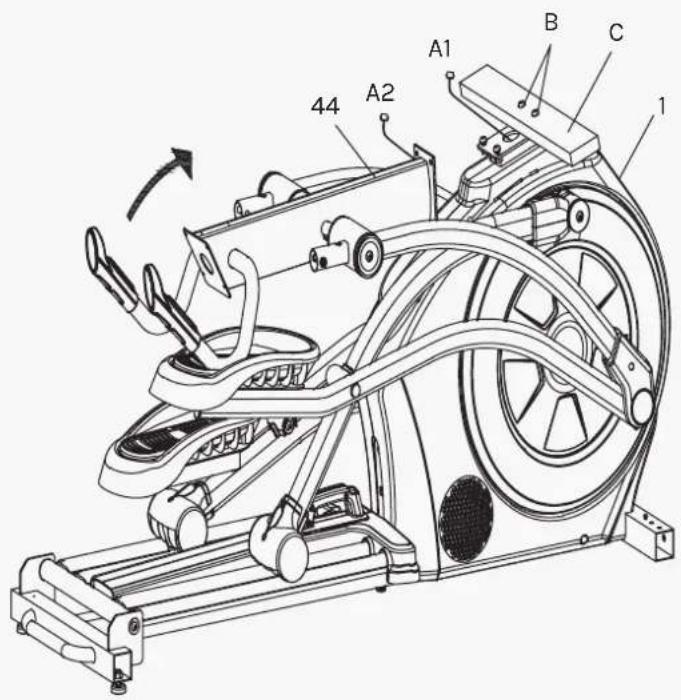

STEP 1
-
Remove the pre-lock board (C) and two bolts (B) at the front end of the main frame assembly (1) and throw them away. Follow-up installation steps are not needed.
-
As shown in the figure, turn the upper column assembly (44) in the direction of arrow until the upper column assembly (44) is close to the main frame assembly (1). One person holds the upper column assembly (44) and the other person connects the signal line (A1-A2) after the connection is completed. The terminal is inserted into a large sheet metal hole on the main frame assembly (1) to avoid overwhelming the signal line.
-
As shown in the figure, the sheet metal on the upper column assembly (44) is clamped into the main frame assembly (44) which is pre-locked.

-
As shown in the figure, the main frame assembly (1) is padded with packing material (A), and the screw (33), (34) which is pre-locked on the connecting pipe assembly of the left and right front foot tubes and the upper screw (21) of the main frame assembly (1) are put on the side and back for assembly.
-
The right front foot connecting pipe assembly (3) is inserted into the square pipe corresponding to the main frame assembly (1) and locked with three M8*20 internal hexagonal screws (33) and eight elastic gaskets (34). The other side is assembled in the same way.
-
Remove the packing material (A) padded under the main frame assembly (1). Cover the front cover (40) on the square pipe at the front end of the main frame assembly (1). Lock it with two 4.2*19 cross groove disc head screws (21).

- As shown in the figure, remove two 4.2*19 cross groove head tapping screws (21) pre-locked on the main frame assembly (1) and lock the rear cover (41) on the main frame assembly (1).

- As shown in the figure, the chain cover rear cover (43) and chain cover front cover (43) is assembled on the main frame assembly (1).

-
As shown in the figure, the wires under the electronic meter (51) are connected together according to (A1-A2) (B1-B2) (C1-C2) (D1-D2) (E1-E2) I, and the terminals are inserted into the large sheet metal hole on the instrument tube assembly (44) to avoid overwhelming the signal line.
-
Finally, the electronic meter (51) is fixed to the instrument tube assembly (44) with four M5*8 cross groove head screws on the electronic meter (51).
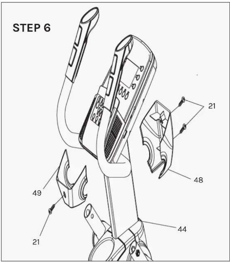
- As shown in the figure, three screws (21) which are pre-locked on the instrument tube assembly (44) are removed first. Then, the instrument back cover (49) and the instrument front cover (48) are fixed on the instrument tube assembly (44) with three self-tapping screws (21) with 4.2*19 cross groove disk head.

- As shown in the figure, remove four M8*45 hexagonal head screws and four M8 anti-loosening nuts that are pre-locked on the left- and right-hand rocker tube (72) (73).
- Then two shaker caps (75) are inserted into the left and right shaker caps (72) (73). Insert the left handshake tube (72) into the left handshake tube assembly circular tube and lock it with two M8*45 hexagonal head screws and two M8 anti-loosening nuts (pay attention to the direction of the head of the screw).
- Finally, put down the shaker cover (75). The assembly steps on the other side are the same.
- Plug the power adapter into the cross trainer and to power point. The cross trainer power plug area is located at the front wheel of the cross trainer near the feet.
VI. COMPUTER OPERATION
Functions
Program: 21 programs as following
A: 1 Manual Program

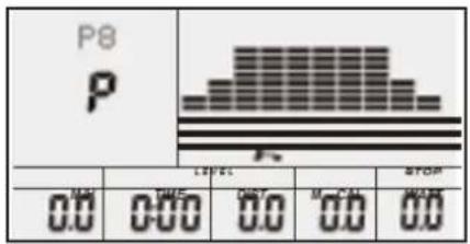
B: 10 Preset Program Profile


bar
| Category | Value | |---|---| | TIME | 0.0 | | DIST | 0.0 | | CALL | 0.0 | | WAIT | 0.0 | | STOP | 1.2 |


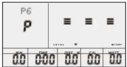



C: 1 Watt Control Program

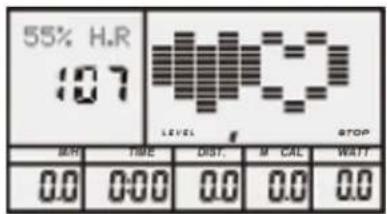
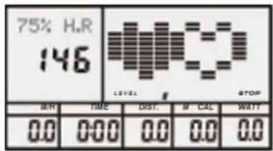
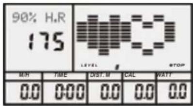
D: 4 Heart Rate Control Program
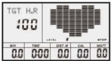
E: 4 User Setting Programs: CUSTOM1 TO CUSTOM4


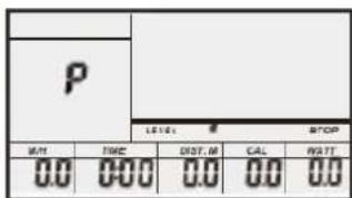

F: 1 Body Fat Measuring Program


- Record the user's data of GENDER, HEIGHT, WEIGHT and AGE even cut off the power.
- Dot matrix display showing your current status. (See fig.22)
- Simulative ECG measuring the heart rate (See fig.23)
- Display Speed (RPM), TIME, DIST., CAL., WATT, PULSE, LEVEL at the same time.
- The computer will turn off automatically if there is no operation, speed signal and pulse signal over 4 minutes. Meanwhile, it will store your current exercise data and turn the loading resistance to the minimum. Once you press any button or in motion, the computer will turn on automatically.
Buttons
1. ENTER
- In "stop" mode (display STOP), press ENTER button to enter program selection and setting value which flash in related window.
A: When you choose the program, press Enter to confirm the one you like.
B: When in setting, press ENTER to confirm the value that you would like to preset.
- During the start mode (display START), press ENTER to choose to display the speed or RPM or switch automatically.
2. START/STOP:
- Press START/STOP button to start or stop the programs.
- During any mode, hold down this button for 2 seconds to totally reset the computer.
3. UP:
- In stop mode and the dot matrix character flash, press this button (or rotate clockwise) to select the program up. If the related window value flash, press this button (or rotate clockwise) to increase the value.
- During the start mode (display START), press this button (or rotate clockwise) to increase the training resistance.
4. DOWN:
- In stop mode and the dot matrix character flash, press this button (or rotate anticlockwise) to select the program down. If the related window value flash, press this button (or rotate anticlockwise) to decrease the value.
- During the start mode (display START), press this button (or rotate anticlockwise) to decrease the training resistance.
5. PULSE RECOVERY
- First test your current heart rate and show your heart rate value, press this button to enter pulse recovery testing. When you are in pulse recovery mode, press this button to exit.
6. RESET (IF HAVE)
- When in setting, press RESET to reset the value that you would like to preset.
- During any mode, hold down this button for 2 seconds to totally reset the computer.

NOTE:
1: To press or rotate of UP, DOWN button should be followed by different model.
2: It is suggested to cover your finger within the marked region to select functions in case of any wrong action.
Operation
1. Turn on the computer
Plug in one end of the adaptor to the AC electrical source and connect the other end to the computer. The computer will beep and enter initial mode.
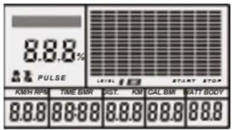
2. Program select and value setting
- Manual Program and Pre-set Program P1\~P10
A. Press (or rotate) UP, DOWN button to select the program that you like.
B. Press ENTER button to confirm the selected program and enter time setting window.
C. The time will flash, and then press (or rotate) UP, DOWN button to set up your desired time. Press ENTER to confirm the value.

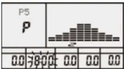
D. The distance will flash, and then press (or rotate) UP, DOWN button to set up the desired distance value. Press ENTER to confirm the value.
E. The calories will flash, and then press (or rotate) UP, DOWN to set up the desired calories to be consumed. Press ENTER to confirm the value.
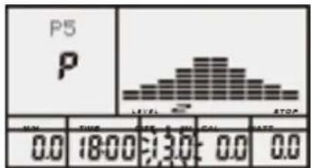

F. Press START/ STOP to begin exercise.
- Watt Control Program
A. Press (or rotate) UP, DOWN to select the watt control program.
B. Press ENTER to confirm the selected watt control program and enter time setting window.
C. The time will flash, and then press (or rotate) UP, DOWN button to set up the desired time. Press ENTER to confirm the value.
D. The distance will flash, and then press (or rotate) UP, DOWN button to set up the desired distance value. Press ENTER to confirm the value.
E. The calories will flash, and then press (or rotate) UP, DOWN button to set up the desired calories to be consumed. Press ENTER to confirm the value.
F. The watt display will flash, and then press (or rotate) UP, DOWN button to set up the watt to do the exercise. Press ENTER to confirm the value.
G. Press START/ STOP to begin exercise.

bar
| Category | Value | |---|---| | P5 | 111 | | P | 16:59 | | LEVEL 1 | 12.7 | | START | 108 | | START | 29.7 |

NOTE:
The WATT value is decided by the TORQUE and RPM. In this program, the WATT value will keep at constant value. It means that if you pedal quickly, the load resistance will decrease and if you pedal slowly, the load resistance will increase to ensure you are at the watt value.
• HEART RATE CONTROL PROGRAM: 55% H.R, 75% H.R and 90% H.R
The maximum heart rate depends on different age and this program will ensure you do the healthy exercise within maximum heart rate.
A. Press (or rotate) UP, DOWN button to choose the heart rate control program.
B. Press ENTER to confirm the heart rate control program and enter time setting window.
C. The time will flash, and then press (or rotate) UP, DOWN button to set up the desired time. Press ENTER to confirm the value.
D. The distance will flash, and then press (or rotate) UP, DOWN button to set up the desired distance value. Press ENTER to confirm the value.


E. The calories will flash, and then press (or rotate) UP, DOWN button to set up the desired calories to be consumed. Press ENTER to confirm the value.
F. The age will flash, and then press (or rotate) UP, DOWN button to set the user's age. Press ENTER to confirm the value.
G. When the target heart rate control program flash, the computer will display the user's target heart rate according to user's age.
H. Press START/ STOP to begin exercise.
- HEART RATE CONTROL PROGRAM: TARGET HEART RATE The user can set any target heart rate to do the exercise.
A. Press (or rotate) UP, DOWN button to select TARGET HEART RATE program.
B. Press ENTER to confirm your choice and enter time setting window.
C. The time display will flash, and then press (or rotate) UP, DOWN button to set the desired time to do the exercise. Press ENTER to confirm the value.
D. The distance will flash, and then press (or rotate) UP, DOWN button to set up the desired distance value. Press ENTER to confirm the value.
E. The calories will flash, and then press (or rotate) UP, DOWN button to set up the desired calories to be consumed. Press ENTER to confirm the value.
F. The target heart rate will flash, and then press (or rotate) UP, DOWN button to set up your target heart rate. Press ENTER to confirm the value.
G. Press START/ STOP to begin exercise.

NOTE:
During exercise, the user's heart rate value depends on resistance level and speed. The heart rate control program is to ensure your heart rate within the preset value. When the computer detects your current heartrate is higher than preset, it will decrease the resistance level automatically or you may slow down exercise. If your current heart rate is lower than preset, it will increase resistance and you may speed up.
• Body Fat Measurement Program
A. Press (or rotate) UP, DOWN button to select BODY FAT TEST program


B. Press ENTER to confirm your choice, and enter height setting mode
C. The height display will flash, and then press (or rotate) UP, DOWN button to set up your height. Press ENTER to confirm the value.
D. The weight display will flash, and then press (or rotate) UP, DOWN button to set up your weight. Press ENTER to confirm the value.


E. The age display will flash, and then press (or rotate) UP, DOWN button to set up your age. Press ENTER to confirm the value.
F. The gender display will flash, and then press (or rotate) UP, DOWN button to set up your gender. Press ENTER to confirm. Press ENTER to confirm the value.
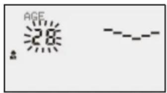

G. Press START/STOP to begin testing your body fat.
NOTE:
- During the body fat measurement, place both your palms on the contact pads. The test result is: FAT%, BMR (Basal Metabolic Rate), BMI (Body Mass Index), BODY and body shape.


FAT%: The total body fat in our body measured by percentage.
BMR: Basal Metabolic Rate (metabolism) is the energy (measured in calories) expended by the body at rest to maintain normal bodily function.
BMI: means Body Mass Index, which is used for body shape building
- During the body fat measurement, if your palms do not contact the pulse sensor well, the computer cannot receive any signal and it will display ERROR2. Press START/STOP to try again.
- During the test, you cannot exit the test when press any button. After the test finish, press (or rotate) UP, DOWN button to exit the body fat measurement program and switch to another program.
- Comparison sheet of body fat and Obese
| Age/Gender\Body Shape | Slim | Healthy | Fleshy | Over WT | Obese |
| BODY1 | BODY2 | BODY3 | BODY4 | BODY5 | |
| Male/≤30 years old | <14% | 14%~20% | 20.1%~25% | 25.1%~35% | >35% |
| Male/>30 years old | <17% | 17%~23% | 23.1%~28% | 28.1%~38% | >38% |
| Female/≤30 years old | <17% | 17%~24% | 24.1%~30% | 30.1%~40% | >40% |
| Female/>30 years old | <20% | 20%~27% | 27.1%~33% | 33.1%~43% | >43% |
3. Pulse Recovery Test
The pulse recovery test is to compare your heart rate before and after exercise. It is targeted to determine your heart strength via the measuring. Please do the test as below:
A. Both your hands hold the pulse sensor or via wireless transmitter belt to test the pulse (if applicable), the computer will display your current pulse value.
B. Press RECOVERY to enter the pulse recovery test and the computer program will enter the stop status.
C. Keep pulse detecting.
D. Time will count down from 60 seconds to 0 second.
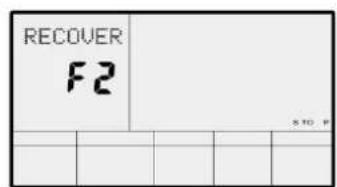
E. When time reaches 0, the test result (F1-F6) appears on the display.
F1=Excellent F2=Good F3=Fair F4=below average F5=No Good F6=Poor.
F. If the computer does not detect your current heart rate first, pressing RECOVERY will not enter pulse recovery test. During the pulse recovery test, press RECOVERY to exit the test and return to the stop status.

3. Pulse Measurement
Please place both your palms on the contact pads and the computer will show your current heartbeat rate in beats per minute (BPM) on the LCD after 3\~4 seconds. During the measurement, heart icon will flash with simulative ECG showing.

REMARK:
During the process of pulse measurement, because of the contact jamming, the measurement value may not be stable when start, then it will return to normal level. The measurement value cannot be regarded as the basis of medical treatment.

NOTE:
If the computer is also equipped with wireless heart rate measuring via the transmitter belt, and with hand pulse function, the hand-measurement-signal-detecting is preferred.
Specifications
| SPEED KM/H (M/H): | Showing your current speed. Range: 0.0~99.9 KM/H (M/H). |
| TIME: | The accumulative exercise time, range: 0:00~99M59S. The preset time range is 5:00~99M00S. The computer will start to count down from preset time to 0:00 with average time for each resistance level. When it reaches to zero, the program will stop and computer alarm. If you do not preset the time, it will run with one-minute decrement each resistance level. |
| DIST: | The exercise accumulative distance. Range: 0.0~99.9~999KM (MILE) the pre-set distance range :1.0~99.0~999. When the distance reaches 0, the program will stop, and the computer will alarm. |
| CALORIE: | The exercise accumulative calories burnt. Range: 0.0~99.9~999 the preset calories range :10.0~90.0~990. When the calorie reaches 0, the program will stop, and the computer will alarm. |
| PULSE: | Showing the exercise heart rate value. Range: 30~240BPM (beat per minute) |
| RESISTANCE LEVEL: | Showing resistance level. Range: 1~16 |
| WATT: Show the exercise watt | |
ERROR CODES
Error 1: Check if the motor is running and if the motor wires are properly connected.
Error 2: It is not detecting your pulse, ensure both hands are on the sensor for a body fat reading.
! PLEASE NOTE:
Before beginning any exercise program, consult your physician. This is important especially if you are over the age of 45 or individuals with pre-existing health problems.
The pulse sensors are not medical devices. Various factors, including the user's movement, may affect the accuracy of heart rate readings. The pulse sensors are intended only as an exercise aid in determining heart rate trends in general.
Exercising is great way to control your weight, improving your fitness and reduce the effect of aging and stress. The key to success is to make exercise a regular and enjoyable part of your everyday life.
The condition of your heart and lungs and how efficient they are in delivering oxygen via your blood to your muscles is an important factor to your fitness. Your muscles use this oxygen to provide enough energy for daily activity. This is called aerobic activity. When you are fit, your heart will not have to work so hard. It will pump a lot fewer times per minute, reducing the wear and tear of your heart.
So as you can see, the fitter you are, the healthier and greater you will feel.

natural_image
Four sequential line drawings of a person performing a stretching or martial arts pose, no text or symbols present.WARM UP
Start each workout with 5 to 10 minutes of stretching and some light exercises. A proper warm-up increases your body temperature, heart rate and circulation in preparation for exercise. Ease into your exercise.
After warming up, increase the intensity to your desired exercise program. Be sure to maintain your intensity for maximum performance. Breathe regularly and deeply as you exercise.
COOL DOWN
Finish each workout with a light jog or walk for at least 1 minute. Then complete 5 to 10 minutes of stretching to cool down. This will increase the flexibility of your muscles and will help prevent post-exercise problems.
WORKOUT GUIDELINES
line
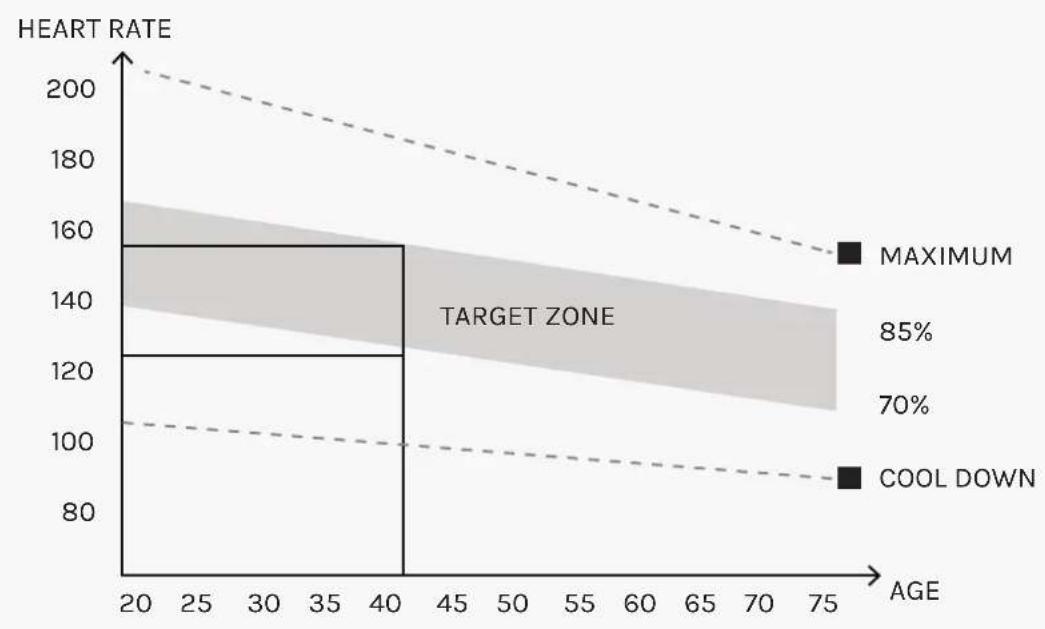
| AGE | HEART RATE | | --- | ---------- | | 20 | 160 | | 40 | 120 | | 75 | 90 |This is how your pulse should behave during general fitness exercise. Remember to warm up and cool down for a few minutes.
VIII. WARRANTY
AUSTRALIAN CONSUMER LAW
Many of our products come with a guarantee or warranty from the manufacturer. In addition, they come with guarantees that cannot be excluded under the Australian Consumer Law. You are entitled to a replacement or refund for a major failure and compensation for any other reasonably foreseeable loss or damage.
You are entitled to have the goods repaired or replaced if the goods fail to be of acceptable quality and the failure does not amount to a major failure. Full details of your consumer rights may be found at www.consumerlaw.gov.au.
Please visit our website to view our full warranty terms and conditions:
http://www.lifespanfitness.com.au/warranty-repairs
WARRANTY AND SUPPORT
Any claim against this warranty must be made through your original place of purchase. Proof of purchase is required before a warranty claim may be processed.
If you have purchased this product from the Official Lifespan Fitness website, please visit https://lifespanfitness.com.au/warranty-form
For support outside of warranty, if you wish to purchase replacement parts or request a repair or service, please visit https://lifespanfitness.com.au/warranty-form and fill in our Repair/Service Request Form or Parts Purchase Form.
Scan this QR code with your device to go to lifespanfitness.com.au/warranty-form

IX. HAND PULSE TECHNOLOGY
This product comes equipped with hand pulse sensors which are used to pick up tiny EKG/ECG signals that run through the body when your heart beats. These electrical EKG/ECG signals are very small and that they must be amplified 1000 times to make the signal useful for the computer to display your pulse.
To ensure proper operation:
- The user must maintain good, consistent contact on all four sensors.
- The users skin cannot be too dry or too wet.
Other factors that could affect the reading:
- Change of grip on the sensors (during slow pace walking and up to running).
- Tightening of hand muscles will produce small electrical signals.
- Static electricity charges from the air or from walking on the treadmill.
EKG/ECG Sensors may filter through actual EKG/ECG signals and "Noise" factors that may affect the reading. This will cause the pulse reading to be delayed and will take longer to update the display as the heart rate changes. Too much noise will create an incorrect reading. Medical conditions or having no electrical signal in the hands are other factors that may affect pulse readings as well.
These are limitations of hand pulse technology and even the most expensive systems (which can cost upwards of \$3,000) used in hospitals have the same problems. The difference is that a patient in a hospital is not running on a treadmill. Hand pulse technology works well on stationary exercise machines like bikes and even elliptical cross trainers but are not perfect on a treadmill. We offer treadmills with a wireless heart rate receiver which may be a more accurate option.
To test if your hand pulse sensors are working up to specification, hold them while standing on the sidestep rails, not walking, and see if the reading is more in line with what you would expect. This will eliminate the movement and static electricity factors. If your hands are dry, then wet them slightly (saliva works as a great conductor if this doesn't bother you).

- XT-40 Ascender Incline Cross Trainer
- IMPORTANT
- TABLE OF CONTENTS
- IMPORTANT SAFETY INSTRUCTIONS
- WARNING: Read all instructions before using this machine.
- CARE INSTRUCTIONS
- EXPLODED DIAGRAM
- PARTS LIST
- ASSEMBLY INSTRUCTIONS
- STEP 1
- COMPUTER OPERATION
- Functions
- CAL
- Buttons
- ENTER
- START/STOP:
- UP:
- DOWN:
- PULSE RECOVERY
- RESET (IF HAVE)
- NOTE:
- Operation
- Turn on the computer
- Program select and value setting
- Pulse Recovery Test
- Pulse Measurement
- REMARK:
- ERROR CODES
- ! PLEASE NOTE:
- WARM UP
- COOL DOWN
- WORKOUT GUIDELINES
- WARRANTY
- AUSTRALIAN CONSUMER LAW
- WARRANTY AND SUPPORT
- HAND PULSE TECHNOLOGY
Brand : LifeSpan
Model : XT-40
Category : Elliptical bike