TB-6R - Intercom Sonifex - Free user manual and instructions
Find the device manual for free TB-6R Sonifex in PDF.


| Product Type | 6-Way Talkback Intercom, 19-inch Rack Mounted |
| Model | TB-6R |
| Brand | Sonifex |
| Dimensions (H x W x D) | 8.9 cm (2U) x 48.3 cm (19") x 18.5 cm |
| Net Weight | 2.60 kg |
| Gross Weight | 4.0 kg |
| Power Supply | 85-264 V AC, 47-63 Hz, max 10 W |
| Power Connector | IEC, with fuse holder (1A anti-surge) |
| Talkback Channels | 6 balanced outputs, 1 balanced input (DC signalling) |
| Talkback Input Gain Range | -28 dB to +9 dB (rear preset) |
| Microphone Type | Built-in electret or external (XLR), selectable via rear switch |
| Microphone Gain Range | 53 dB to 74 dB (rear preset) |
| External Input 1 | Balanced stereo line level on 9-pin D-sub |
| External Input 2 | Unbalanced stereo (phono and 9-pin D-sub) |
| Monitor Speaker | 1 W mono, internal |
| Headphone Output | 6.35 mm jack, 150 mW into 32-600 Ω |
| Front Panel Controls | Power LED, volume, EXT1/EXT2 select, 6 talkback buttons, built-in mic |
| Rear Panel Connectors | Headphone jack, mic select, mic gain, talkback gain, EXT2 phono, EXT inputs & mute (9-pin D-sub), talkback I/O (15-pin D-sub), fuse, IEC |
| Configuration Jumpers | Internal: muting/mixing of external inputs during talkback, local/external talkback |
| Compatibility | Sonifex S2 mixer, other DC-signalling talkback systems |
| Safety & Compliance | CE, WEEE, RoHS, 12-month warranty |
| Cleaning | Wipe with soft dry cloth; no liquids |
| User Serviceable Parts | None; refer to qualified service personnel |
Frequently Asked Questions - TB-6R Sonifex
User questions about TB-6R Sonifex
0 question about this device. Answer the ones you know or ask your own.
Ask a new question about this device
Download the instructions for your Intercom in PDF format for free! Find your manual TB-6R - Sonifex and take your electronic device back in hand. On this page are published all the documents necessary for the use of your device. TB-6R by Sonifex.
USER MANUAL TB-6R Sonifex
natural_image
Collage of industrial control equipment including a T-6R device, a 5000 MHz spectrometer, and a Station Number (SOMFES) with visible ports and cables against a blue abstract background.
natural_image
Abstract circular design with concentric curved lines, no text or symbols presentStation Master &
Talkback Intercoms
User Handbook

SONIFEX

This handbook covers the following product stock codes:
SM-24 Station Master for 2 studios (PPM and VU)
SM-44 Station Master for 4 studios (PPM and VU)
SM2 Add on card to upgrade from an SM24 to SM44
TB-6D Talkback Intercom 6 Way, desktop free standing
TB-6R Talkback Intercom 6 Way, 19 inch rack mounted
TB-SD Talkback Intercom Station Master, desktop free standing
TB-SR Talkback Intercom Station Master, 19 inch rack mounted
Revision 2.04 February 2020
©Sonifex Ltd, 2000-20
All Rights Reserved
Sonifex Ltd, 61, Station Road, Irthlingborough,
Northants, NN9 5QE, England.
Tel: +44 (0)1933 650 700
Fax: +44 (0)1933 650 726
Email : sales@sonifex.co.uk or technical.support@sonifex.co.uk
Web : http://www.sonifex.co.uk
Information in this document is subject to change without notice and does not represent a commitment on the part of Sonifex Ltd. Sonifex Ltd shall not be liable for any loss or damage whatsoever arising from the use of information or any error contained in this manual.
No part of this manual may be reproduced or transmitted in any form or by any means, electronic or mechanical, including photocopying, recording, or information storage and retrieval systems, for any purpose other than the purchaser's personal use, without the express written permission of Sonifex Ltd.
Unless otherwise noted, all names of companies, products and persons contained herein are part of a completely fictitious adaptation and are designed solely to document the use of Sonifex products.
Warranty & Safety Information i
Warranty and Liability i
Returning the Warranty Card iii
Unpacking the Station Master/Talkback Intercom iii
Safety of Mains Operated Equipment iv
Fuse Rating iv
Power Cable and Connection iv
WEEE & RoHS Directives - Sonifex Statement v
Reporting Faults vi
1 Station Master Introduction 1
Introduction 1
Studio Switching 1
Delay Control 1
Monitoring 2
Audio Distribution 2
Talkback 2
Logging 2
Power Failure 2
Installation Notes 2
Atmosphere 2
Electromagnetic Radiation 2
Connectors and Cabling 3
XLR 3 Pin Connectors 3
1/4" 'A' Gauge Stereo Jack Plugs 3
D-Type Connectors 4
2 Operation 5
Configuration Flowchart 5
Studio Feeds, Transmission Outputs and Logging Outputs 6
Studio Feeds 6
Transmission Outputs 6
Logging Outputs 6
Logging Off-Air instead of Pre-Transmission 6
Monitoring 7
Monitoring Options 8
Enabling Talkback Over the Monitors 8
Mixing or Ducking the Normal Monitor Output During Talkback 9
Fixing the Monitor Output Level for the Phono Connectors 9
Offer and Accept Switching 10
Talkback 11
Delay and Dump Control 13
External Inputs 13
Routing Of External Inputs 13
Altering the External Input Levels 14
3 Connection Details 15
Audio Connections 15
Audio In/Out 1 - 4 16
Studio Controls 17
Controls In/Out 1 & 2 17
Controls In/Out 3 & 4 18
Transmission Outputs 19
Logging Outputs 19
Balanced Logging Outputs 19
Unbalanced Logging Outputs 19
Other Connectors 20

Mains Power 20
Delay/Dump Control 20
External Inputs 21
Monitor Output 22
Monitor Insert 22
Speaker Output 22
Talkback Microphone Input 22
5 Talkback Introduction 26
TB-6D & TB-6R 6 Way Talkback Intercom Overview 27
Example Application For TB-6D & TB-6R 28
TB-SD & TB-SR Station Master Talkback Intercom Overview 29
Example Application For TB-SD & TB-SR 29
Talkback Intercom Benefits 30
Station Master Features 31
Station Master Talkback Operation and Connections 32
6 TB-6D & TB-6R 6 Way Talkback Intercom Configuration & Controls 34
Front Panel Control Details 34
Power LED Indicator 35
Level Control for Monitor Loudspeaker and Headphones 35
External Select Switch 1 35
External Select Switch 2 35
Talkback Switches 35
Built in Electret Microphone 35
Monitor Loudspeaker 35
External Microphone 35
Rear Panel Control Details 36
Headphone Output 36
Mic Select 37
Adjusting the Microphone Gain Level 37
Adjusting the Talkback Gain Level 37
External Input 2 37
External Inputs & Mute Control 37
Talkback Input/Outputs 38
Fuse Holder 38
Mains Input 38
Internal Jumper Configuration 39
Summary of Jumper Settings for the Talkback Unit 39
External Input Muting/Mixing 40
Local/External Talkback 40
TB6 Interconnection Wiring Diagram 42
7 TB-SD & TB-SR Station Master Talkback Intercom Configuration & Controls 43
Front Panel Control Details 43
Power LED Indicator 44
Level Control for Monitor Loudspeaker and Headphones 44
External Select Switch 1 44
External Select Switch 2 44
Talkback Switches 44
Built in Electret Microphone 44
Monitor Loudspeaker 44
External Microphone 44
Rear Panel Control Details 45
Headphone Output 45
Mic Select 46
Adjusting the Microphone Gain Level 46
Adjusting the Talkback Gain Level 46
External Input 2 46
External Inputs & Mute Control 46
Station Master Remotes 47
Fuse Holder 47
Mains Input 47
Internal Jumper Configuration 48
Summary of Jumper Settings for the Talkback Unit 48
External Input Muting/Mixing 49
Local/External Talkback 49
8 Talkback Intercom Technical Specification 51
Audio & Power Specification 51
Physical Specification
52


Figures
Fig 1-1: XLR-3 Connectors. 3
Fig 1-2: ¼" Jack Connectors 3
Fig 1-3: D-Type Connectors. 4
Fig 2-1: Station Master Block Diagram. 5
Fig 2-2 : Monitor Section of the Front Panel. 7
Fig 2-3: Station Master Viewed From Above Showing Jumper Positioning. 8
Fig 2-4: Station Master Offer & Accept Status. 10
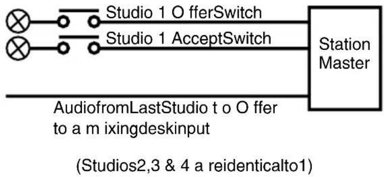
Fig 2-5 : Offer & Accept Switches for Studio 1. 10
Fig 2-6: Front Panel Talkback Switches & Mic Input. 12
Fig 5-1: TB-6D Talkback Intercom 6 Way Desktop & TB-SD Talkback Intercom Station Master Desktop. 26
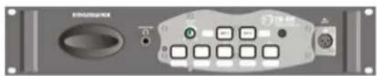
Fig 5-2: TB-6R Talkback Intercom 6 Way Rack & TB-SR Talkback Intercom Station Master Rack. 26
Fig 5-3: Example Application For TB-6D & TB-6R. 28
Fig 5-4: Example Application For TB-SD & TB-SR. 29
Fig 5-5: Talkback Intercom System Block Diagram. 33
Fig 6-1: TB-6D Front Panel. 34
Fig 6-2: TB-6R Front Panel. 34
Fig 6-3: TB-6D Rear Panel. 36
Fig 6-4: TB-6R Rear Panel. 36
Fig 6-5: TB-6D & TB-6R Board Layout. 39
Fig 6-6: Connecting The Talkback Intercom To The Sonifex S2 Mixer Output Module (S2-OMC). 41
Fig 6-7: Interconnection Wiring Diagram 42
Fig 7-1: Front Panel Controls for TB-SD. 43
Fig 7-2: Front Panel Controls for TB-SR. 43
Fig 7-3: TB-SD Rear Panel. 45
Fig 7-4: TB-SR Rear Panel. 45
Fig 7-5: TB-SD & TB-SR Board Layout. 48
Fig 7-6: Connecting The Talkback Intercom To The Sonifex S2 Mixer Output Module (S2-OMC). 50
Warranty & Safety Information
Warranty and Liability
Important: the purchaser is advised to read this clause
(a) The Company agrees to repair or (at its discretion) replace Goods which are found to be defective (fair wear and tear excepted) and which are returned to the Company within 12 months of the date of despatch provided that each of the following are satisfied:
(i) notification of any defect is given to the Company immediately upon its becoming apparent to the Purchaser;
(ii) the Goods have only been operated under normal operating conditions and have only been subject to normal use (and in particular the Goods must have been correctly connected and must not have been subject to high voltage or to ionising radiation and must not have been used contrary to the Company's technical recommendations);
(iii) the Goods are returned to the Company's premises at the Purchaser's expense;
(iv) any Goods or parts of Goods replaced shall become the property of the Company;
(v) no work whatsoever (other than normal and proper maintenance) has been carried out to the Goods or any part of the Goods without the Company's prior written consent;
(vi) the defect has not arisen from a design made, furnished or specified by the Purchaser;
(vii) the Goods have been assembled or incorporated into other goods only in accordance with any instructions issued by the Company;
(viii) the defect has not arisen from a design modified by the Purchaser;
(ix) the defect has not arisen from an item manufactured by a person other than the Company. In respect of any item manufactured by a person other than the Company, the Purchaser shall only be entitled to the benefit of any warranty or guarantee provided by such manufacturer to the Company.


(b) In respect of computer software supplied by the Company the Company does not warrant that the use of the software will be uninterrupted or error free.
(c) The Company accepts liability:
(i) for death or personal injury to the extent that it results from the negligence of the Company, its employees (whilst in the course of their employment) or its agents (in the course of the agency);
(ii) for any breach by the Company of any statutory undertaking as to title, quiet possession and freedom from encumbrance.
(d) Subject to conditions (a) and (c) from the time of despatch of the Goods from the Company's premises the Purchaser shall be responsible for any defect in the Goods or loss, damage, nuisance or interference whatsoever consequential economic or otherwise or wastage of material resulting from or caused by or to the Goods. In particular the Company shall not be liable for any loss of profits or other economic losses. The Company accordingly excludes all liability for the same.
(e) At the request and expense of the Purchaser the Company will test the Goods to ascertain performance levels and provide a report of the results of that test. The report will be accurate at the time of the test, to the best of the belief and knowledge of the Company, and the Company accepts no liability in respect of its accuracy beyond that set out in Condition (a).
(f) Subject to Condition (e) no representation, condition, warranty or other term, express or implied (by statute or otherwise) is given by the Company that the Goods are of any particular quality or standard or will enable the Purchaser to attain any particular performance or result, or will be suitable for any particular purpose or use under specific conditions or will provide any particular capacity, notwithstanding that the requirement for such performance, result or capacity or that such particular purpose or conditions may have been known (or ought to have been known) to the Company, its employees or agents.
(g) (i) To the extent that the Company is held legally liable to the Purchaser for any single breach of contract, tort, representation or other act or default, the Company's liability for the same shall not exceed the Price of the Goods.
(ii) The restriction of liability in Condition (g)(i) shall not apply to any liability accepted by the Seller in Condition (c).
(h) Where the Goods are sold under a consumer transaction (as defined by the Consumer Transactions (Restrictions on Statements) Order 1976) the statutory rights of the Purchaser are not affected by these Conditions of Sale.
Returning the Warranty Card
In order to register the date of purchase so that we can keep you informed of any design improvements or modifications, it is important to complete the warranty registration document that is enclosed and return it to Sonifex Ltd in the UK, or register online at www.sonifex.co.uk/register
For your own records you should write down the serial number (which can be found at the rear of the product.
| Serial Number |
Unpacking the Station Master/Talkback Intercom
Each product is shipped in protective packaging and should be inspected for damage before use. Where an item is found to have transit damage, notify your supplier immediately with all the relevant details of the shipment. Packing materials should be kept for inspection and also for if the product needs to be returned.


Safety of Mains Operated Equipment
CE This equipment has been designed to meet the safety regulations currently advised in the country of purchase and it conforms to the safety regulations specified by use of the CE Mark.
The power supply is rated to 95 - 265VAC at 47 - 63Hz with a fuse of 2A.
Warning: There are no user serviceably parts inside the machine. If you should ever need to look inside the unit, always disconnect the mains supply before removing the equipment covers.
Fuse Rating
The product is supplied with a single fuse in the live conducting path of the power-in feed at the power supply. For reasons of safety it is important that the correct rating and type of fuse is used. Incorrectly rated fuses could present a possible fire hazard, under equipment fault conditions.
Power Cable and Connection
An IEC power connector is supplied with the product, which has a moulded plug attached – this is a legal requirement. If no moulded plug has been supplied with your product, please contact your supplier, because an IEC connector is always supplied from the Sonifex factory.
If for any reason, you need to use the product with a different power cable, you should use the following wiring guidelines
Wire Colour Connection
Green, or green and yellow Earth (E)
Blue, or Black Neutral (N)
Brown, or Red Live (L)
WEEE & RoHS Directives - Sonifex Statement

The Waste Electrical and Electronic Equipment (WEEE) Directive was agreed on 13 February 2003, along with the related Directive 2002/95/EC on Restrictions of the use of certain Hazardous Substances in electrical and electronic equipment (RoHS).
The Waste Electrical and Electronic Equipment Directive (WEEE) aims to minimise the impacts of electrical and electronic equipment on the environment during their life times and when they become waste. It applies to a huge spectrum of products. It encourages and sets criteria for the collection, treatment, recycling and recovery of waste electrical and electronic equipment. All products manufactured by Sonifex Ltd have the WEEE directive label placed on the case. It gives a contact for individuals who are unsure about the correct procedure when the product has reached its “end of use”.
Sonifex Ltd will be happy to give you information about local organisations that can reprocess the products, or alternatively all products that have reached “end of use” can be returned to Sonifex and will be reprocessed correctly free of charge.
Sonifex Ltd has phased out the use of certain hazardous substances identified in the European Union's Restriction of Hazardous Substances (RoHS) directive. The RoHS directive limits the use of certain hazardous substances currently used in EEE manufacture, including lead, mercury, cadmium, hexavalent chromium, and halide-containing compounds PBB (polybrominated biphenyl) and PBDE (polybrominated diphenyl ether). Elimination of these substances will result in more environmentally friendly recycling of electronic equipment. For the products which Sonifex manufacture, the main area where products were affected was in the use of lead for manufacturing and assembling electronics circuit boards.
Sonifex Ltd practices lead-free (LF) manufacturing processes. LF solder is used on the surface-mount PCB manufacturing processes and for hand soldering. The printed circuit boards (PCBs) used are either gold plated, or immersion tin plated, both of which use no lead. Historically the PCBs were hot air solder levelled (HASL) PCBs which used tin/lead based solder.
The manufacturing processes include the assembly of purchased components from various sources. Product is offered as RoHS compliant, or LF, only after sufficient evidence is received from the component manufacturers that their components are RoHS compliant. Sonifex Ltd relies solely on the distributor, or manufacturer, of the components for identification of RoHS compliance. Thus whilst every effort is made to ensure compliance, Sonifex Ltd makes no warranty, or certification, or declaration of compliance concerning said components.
Sonifex Ltd defines "Lead Free" as pertaining to any product, which has been manufactured by Sonifex Ltd using components which have been declared by the manufacturers as "Lead Free". All statements by Sonifex Ltd of RoHS compliance are based on component manufacturer documentation.


Reporting Faults
Although this Sonifex product is manufactured to the highest standards, it is possible that minor faults may appear in the equipment over its normal lifetime. If you find any problems with the product, please contact your Sonifex distributor, or contact Sonifex directly at the following address, or fax with a copy of this completed sheet:
| To : From: | |
| Sonifex Ltd, Name | |
| 61, Station Road, Position | |
| Irthlingborough, Company | |
| Northants. Address | |
| NN9 5QE, UK | |
| Tel : +44 (0)1933 650 700 Tel | |
| Fax : +44 (0)1933 650 726 Fax | |
| Email : technical.support@sonifex.co.uk Email |
For the Serial No. of your machine, see the back panel of the unit.
Serial No.
Please describe the error in as much detail as possible (for example what you were doing when the problem occurred, what actually happened, etc)
Description of Error
Also, if you have any suggestions for additions or upgrades to the unit, we would like to hear what they are:
Additions that I Would Like to See
1 Station Master Introduction
Introduction
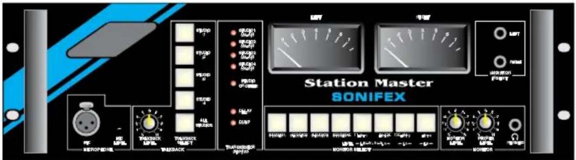
Station Master is an addition to the Sonifex range of professional audio products designed for building radio stations on a budget. It combines all the black boxes required for audio distribution, studio switching, talkback and monitoring for up to 4 studios into a single package. The Station Master has a number of benefits:
- Saves money - combining several features into one unit gives significant cost savings over purchasing the discrete parts that Station Master replaces, without any compromise on quality.
• Easy to install - single unit simplifies installation. - Requires less space - Station Master is a 3U high 19" single rackmount unit which replaces up to 11U rackspace that discrete components can occupy.
- Reliability - If power to the Station Master fails, it keeps the output routing as set and remembers this state, providing continuity on restoration of power.
Studio Switching
Station Master accepts stereo audio feeds from up to 4 studios, switching them individually to transmission using offer and accept operation. The output of the current 'on-air' studio is distributed to the other studios via a dedicated bus, avoiding the need for multiple studio distribution links.
The output of the Station Master is provided as a stereo pair or a mono feed of the stereo source. The studio switching is achieved using latching relays and therefore retains its switch status in the event of power-failure.
Delay Control
A profanity delay can be controlled by the Station Master allowing you to install just one delay unit that can be shared by your studios and used by the studio currently on air.

1
STATION MASTER INTRODUCTION
Station Master

Monitoring
The Station Master is fitted with either a pair of true PPM meters, or VU meters, for monitoring up to 8 stereo sources. These sources consist of the connected studios and four external sources such as news feeds or off air receivers. The audio can be monitored via headphones or output through a power amplifier capable of driving 10W into 8 speakers. There are also two 1/4" jack insert points for using the Station Master to monitor from a jack-field.
Audio Distribution
Station Master distributes the 4 incoming stereo signals to each of the connected studios without the need for external distribution amplifiers. These signals, such as off-air receivers, news feeds and outside broadcasts, can be professional balanced inputs or at domestic unbalanced line levels. The gain of the incoming stereo signals can be adjusted from the front panel. Distribution gain is controlled by a preset potentiometer.
Talkback
The Station Master's talkback system acts as the master station for talkback with 4 satellite systems. These can either be the connected studios or other locations such as a record library or engineering workshop. Individual satellites can talk to each other or broadcast to all stations.
Logging
To allow for logging of broadcasts the Station Master has a stereo balanced output for professional logging equipment, together with 3 sets of phono unbalanced outputs for connection to domestic VCR equipment.
Power Failure
In the event of a power failure to the Station Master, it will continue to route the current on-air studio to the stereo transmission output. Also, when power is re-applied to the Station Master, all switching, including the offer and accept switching, will instantly re-initialise to the configuration when power was lost. This means that your on-air studio can continue transmitting, even if power to the Station Master has failed.
Installation Notes
Atmosphere
The Station Master should be installed in an area which is not subject to excessive heat or cold. Also, you should avoid installing it in atmospheric conditions which are dusty, smoky or dirty, or where there is moisture or vibration.
Do not use liquids to clean the front of the Station Master - wiping with a soft, dry cloth is advised.
Electromagnetic Radiation
Note that there can be a degradation of the audio quality if the Station Master is used near to strong sources of electromagnetic radiation. Strong sources include video monitors, and mains cabling.
Connectors and Cabling
Many of the problems associated with installing and maintaining studio equipment are due to the use of poor cables or faulty connections. It is recommended that, wherever possible, prewired cables are purchased from recommended manufacturers. If you need bespoke cables making, please ensure that the work is carried out by a qualified engineer.
The main types of connectors used with the Station Master are the following :
XLR 3 Pin Connectors
The following diagram shows the pin details for the 3 pin XLR sockets and plugs :
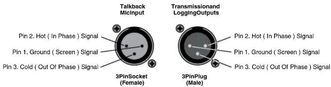
Fig 1-1: XLR-3 Connectors.
1/4" 'A' Gauge Stereo Jack Plugs
1/4" 'A' Gauge Stereo Jack Plugs can be connected as follows :
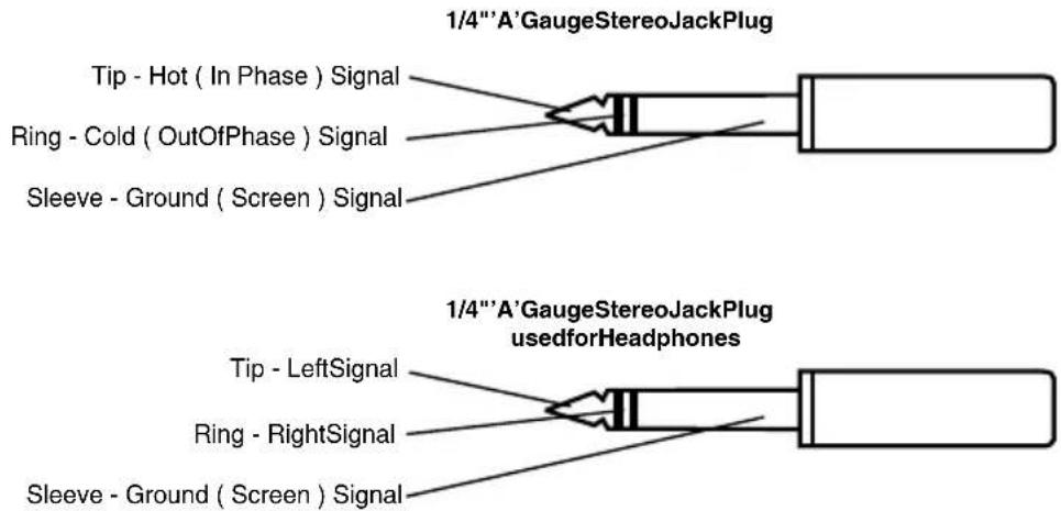
Fig 1-2: ¼" Jack Connectors

1
STATION MASTER INTRODUCTION
Station Master

D-Type Connectors
Three different D-Type connectors are used on the Station Master. A 9 pin plug is used for the Delay/Dump Control. A 25 pin plug is used for the Audio I/O and a 25 pin socket for the Control I/O connector.
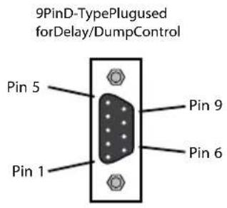
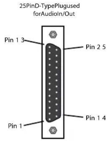
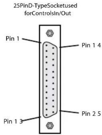
Fig 1-3: D-Type Connectors.
2 Operation
Configuration Flowchart
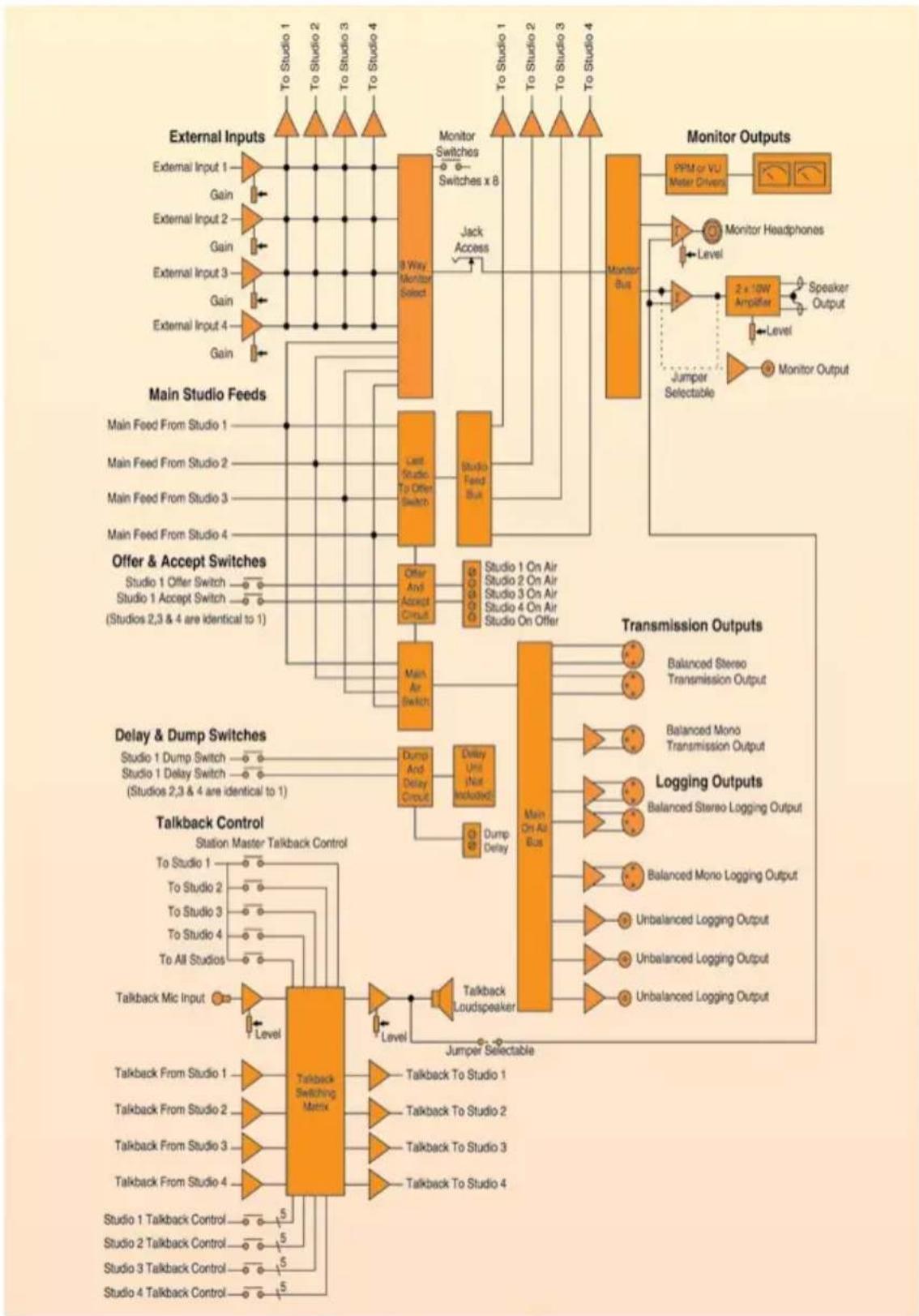
flowchart
graph TD
    subgraph External Inputs
        A1["External Input 1"] --> B1["To Studio 1"]
        A2["External Input 2"] --> B2["To Studio 2"]
        A3["External Input 3"] --> B3["To Studio 3"]
        A4["External Input 4"] --> B4["To Studio 4"]
    end

    subgraph Main Studio Feeds
        C1["Main Feed From Studio 1"] --> D1["Last Studio To Offer Switch"]
        C2["Main Feed From Studio 2"] --> D2["Studio Feed Bus"]
        C3["Main Feed From Studio 3"] --> D3["Studio On Air"]
        C4["Main Feed From Studio 4"] --> D4["Studio On Offer"]
    end

    subgraph Offer & Accept Switches
        E1["Studio 1 Offer Switch"] --> F1["Offer And Accept Circuit"]
        E2["Studio 1 Accept Switch"] --> F2["Studio 1 On Air"]
        E3["(Studios 2,3 & 4 are identical to 1)"]
    end

    subgraph Delay & Dump Switches
        G1["Studio 1 Dump Switch"] --> H1["Dump And Delay Circuit"]
        G2["Studio 1 Delay Switch"] --> H2["Delay Unit (Not Included)"]
        G3["(Studios 2,3 & 4 are identical to 1)"]
    end

    subgraph Talkback Control
        I1["Talkback Mic Input"] --> J1["Level"]
        I2["Talkback From Studio 1"] --> J2["Talkback To Studio 1"]
        I3["Talkback From Studio 2"] --> J3["Talkback To Studio 2"]
        I4["Talkback From Studio 3"] --> J4["Talkback To Studio 3"]
        I5["Talkback From Studio 4"] --> J5["Talkback To Studio 4"]
    end

    subgraph Talkback Switching Matrix
        K1["Talkback Switching Matrix"] --> L1["Talkback To Studio 1"]
        K2["Talkback To Studio 2"]
        K3["Talkback To Studio 3"]
        K4["Talkback To Studio 4"]
        K5["Talkback To Studio 5"]
    end

    subgraph Monitor Outputs
        M1["Monitor Bus"] --> N1["PPM or VU Meter Driven"]
        N1 --> O1["Monitor Headphones"]
        O1 --> P1["Jumper Selectable"]
        P1 --> Q1["Speaker Output"]
        Q1 --> R1["Level"]
        R1 --> S1["Monitor Output"]

    end

    subgraph Transmission Outputs
        T1["Balanced Stereo Transmission Output"]
        T2["Balanced Mono Transmission Output"]
        T3["Logging Outputs"]
        T4["Balanced Stereo Logging Output"]
        T5["Balanced Mono Logging Output"]
        T6["Unbalanced Logging Output"]
        T7["Unbalanced Logging Output"]
        T8["Unbalanced Logging Output"]
    end

    subgraph Jumper Selectable
        U1["Jumper Selectable"]
        U2["Jumper Selectable"]
    end

    style External Inputs fill:#f9f,stroke:#333
    style Main Studio Feeds fill:#ccf,stroke:#333
    style Offer & Accept Switches fill:#cfc,stroke:#333
    style Delay & Dump Switches fill:#fcc,stroke:#333
    style Talkback Control fill:#cff,stroke:#333
Fig 2-1: Station Master Block Diagram.

Studio Feeds, Transmission Outputs and Logging Outputs
Studio Feeds
Station Master takes an audio feed from each connected studio and routes them to the transmission and logging outputs. It uses the offer and accept switching to know which output should be switched to air - as soon as a studio accepts the offer made by the current on-air studio, the output is switched to the accepting studio. The following connections should be made :
The audio feed, from the master output of the mixing desk which you are using in each studio, should be connected to the 25 pin D-type "AUDIO IN/OUT" plug connector, on pins 1, 2, 14 and 15 (marked TRX left/right phase/non-phase). Pin 13 can be used as the screen for these connections. This is the audio feed from the studio to the Station Master.
Once all the studios are connected, you will need to connect the Offer and Accept switching (see the Section marked "Offer and Accept Switching") to ensure that the correct studio is switched to the transmission path.
Transmission Outputs
Depending on whether you are transmitting a mono or stereo signal, you can use either the mono, or stereo balanced XLR-3 transmission outputs to connect the Station Master to a limiter or processor before being sent to the transmitter.
Logging Outputs
Which logging output you use depends on what type of logging equipment you have installed in your radio station. If you are using a balanced "professional" piece of logging equipment, such as the Sonifex Net-Log audio logger, or a balanced PC based recorder, then the balanced XLR-3 outputs should be connected. There are separate stereo and mono outputs.
If you are using "consumer" logging equipment, such as domestic DVD-R recorders, then there are three phono outputs which can be connected. Three outputs have been provided so that three DVD-R's can be used to record longer durations.
Logging Off-Air instead of Pre-Transmission
You can also choose whether to log the transmission output (before it is sent to the transmitter), or whether to log the External Input 1, which could be defined as an off-air receiver, so that you can log what is actually broadcast. On the main motherboard SM-MB-02, check the following jumpers:
| Jumper Set Over Pins Effect | ||
| JP5 | 1 & 2 | The left logging output comes from the transmission path. |
| 2 & 3 | The left logging output comes from External Input 1. | |
| JP6 | 1 & 2 | The right logging output comes from the transmission path. |
| 2 & 3 | The right logging output comes from External Input 1. | |
Note : Items in bold are set as default when shipped.
Set the jumpers over pins 2 & 3 if you want to connect an off-air receiver to External Input 1. See Fig 2-3 for placement of the jumpers on the motherboard.
Monitoring
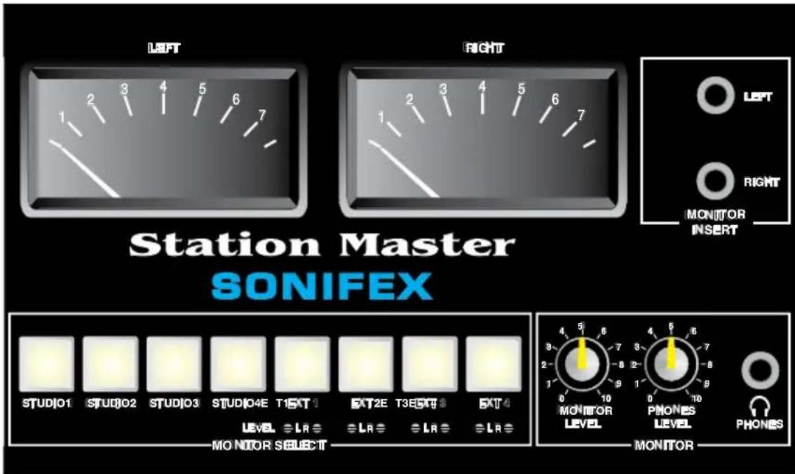
Fig 2-2: Monitor Section of the Front Panel.
- Front panel monitoring is carried out using the eight MONITOR SELECT buttons on the front of the unit. These buttons control which input is sent to the monitor speaker outputs, the monitor outputs, the headphones and the meters.
- The MONITOR INSERT 1/4" jack sockets can be used to monitor left and right signals from a jackfield - they over-ride the MONITOR SELECT selection.
- The "MONITOR LEVEL" volume control alters the level of the output from the monitor speakers and the monitor output.
- The "PHONES LEVEL" volume control alters the level of the output from the headphones.

2
Inside the Station Master there are a number of jumpers that can be altered to change the way that the monitor function operates :
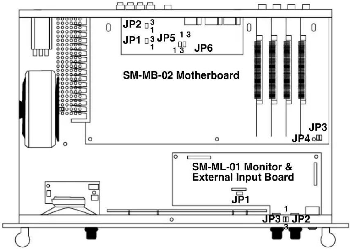
Fig 2-3: Station Master Viewed From Above Showing Jumper Positioning.
Enabling Talkback Over the Monitors
The output of the monitors is normally whatever is selected from the "MONITOR SELECT" buttons on the front panel. You can also have inter-studio talkback sent to the monitors by doing the following. On the Monitor and External Input PCB (SM-ML-01) set jumpers JP2 and JP3 over pins 2 & 3 (see Fig 2-3):
| Jumper Set Over Pins Effect | ||
| JP2 | 1 & 2 | Monitors (left channel) only output the monitor selection. |
| 2 & 3 | Monitors (left channel) output talkback and the monitor selection. | |
| JP3 | 1 & 2 | Monitors (right channel) only output the monitor selection. |
| 2 & 3 | Monitors (right channel) output talkback and the monitor selection. | |
Note : Items in bold are set as default when shipped.
Mixing or Ducking the Normal Monitor Output During Talkback
If the talkback is enabled over the monitors, as above, normally the monitor selection output is ducked while the talkback is output. You can also have the talkback mixed with the monitor selection output by setting jumper JP1 on the monitor and external input PCB (SM-ML-01) (see Fig 2-3):
| Jumper Set Over Pins Effect | ||
| JP1 | 1 & 2Off | If talkback is enabled, it is mixed with the monitor selection.If talkback is enabled, the monitor selection is ducked while the talkback is output. |
Note : Items in bold are set as default when shipped.
Fixing the Monitor Output Level for the Phono Connectors
The monitor output level for the phono connectors can be made either fixed, or affected by the volume control on the front panel of the Station Master. On the main motherboard SMMB-02, check the following jumpers (see Fig 2-3):
| Jumper Set Over Pins Effect | ||
| JP1 | 1 & 2 | Monitor left output on the phonos is at a fixed level. |
| 2 & 3 | Monitor left output on the phonos can be altered by volume control. | |
| JP2 | 1 & 2 | Monitor right output on the phonos is at a fixed level. |
| 2 & 3 | Monitor right output on the phonos can be altered by volume control. | |
Note : Items in bold are set as default when shipped.

2
Offer and Accept Switching
The Station Master can control the Offer and Accept switching for up to four connected studios. This switching also controls which studio output is sent to the transmission and logging outputs and which studio has control of the delay/dump switching.
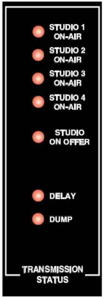
Fig 2-4: Station Master Offer & Accept Status.
The way that offer and accept switching works is that each studio has an Offer and an Accept switch which is routed back to the Station Master. The Station Master has an audio feed to each studio called the "Last Studio to Offer" which should be routed to an input of each studio mixer (Station Master takes this from the transmission output of the current Accepted studio which is already routed to the Station Master).
When a studio is on-air, it has accepted the request to transmit and it's Accept Lamp is illuminated to indicate this. When a studio is reaching the end of its broadcast, the DJ presses the Offer button and the Offer buttons in all connected studios will illuminate to indicate that the transmission is ready to be passed to another studio.
To Accept the offer, a studio must bring up the "Last Studio to Offer" on the mixer (ensuring that the levels are the same as for the outgoing studio - this should be completed beforehand by an engineer), and press the Accept button. The transmission path is then immediately taken from the accepting studio and its' Accept light illuminates. All the Offer lights in the other studios are simultaneously extinguished.
The front panel of the Station Master shows the status of the studios with a LED indication. When the "STUDIO ON OFFER" LED is illuminated, it means that the studio indicated is on offer.
So, the connections for each studio can be summarised as :
flowchart
graph LR
    A["×"] --> B["Studio 1 O fferSwitch"]
    C["×"] --> D["Studio 1 AcceptSwitch"]
    B --> E["Station Master"]
    D --> E
    E --> F["AudiofromLastStudio t o O ffer to a m ixingdeskinput"]
Fig 2-5: Offer & Accept Switches for Studio 1.
Connect the "Last Studio to Offer" balanced audio connection from the Station Master to each studio using pins 3, 4, 16 and 17 of the "Audio In/Out" connector. Pin 13 can be used as a screen.
For each studio, connect Offer and Accept switches to pins 2 and 3 respectively of the "Controls In/Out" connectors. Pins 15 and 16 can be used to power the Offer and Accept lamps respectively.
Note : A standard Offer and Accept switch panel can be ordered which operates with the Sonifex S2 mixer (S2-MTBS) and which also has Delay/Dump controls as well as an Obit indicator.
Talkback
Talkback refers to the standard method of communication between studios - each studio has a row of switch buttons, each one of which connects to another studio when pressed, and routes the presenter audio to it. Station Master can route and control the talkback between up to 4 studios and the Station Master itself (i.e. 5 talkback points). Each studio has the ability to have a row of five switch buttons so that the presenter can talk to the other three studios, the Station Master, or all studios, including the Station Master. So, for each studio, you'll need to make the following connections :
Connect the talkback switches to pins 6, 7, 8, 9, and 10 of the "Controls In/Out" connectors. Pins 19, 20, 21 and 22 can be used to power the lamps for the switches. (When the T/B Switch All button is pressed, all four lamps should be illuminated).
Note : The talkback connection details are slightly different for each studio - ensure that you are connecting to the correct studio.
Connect the unbalanced audio input and output signals, together with the T/B control output to the studio :
- The T/B audio input (pin 23 of the "Controls In/Out" connector) should be connected to the talkback output of the mixing desk in the studio.
- The T/B audio output (pin 12 of the "Controls In/Out" connector) should be connected to the talkback input of the mixing desk in the studio.
- The T/B control signal (pin 13 of the "Controls In/Out" connector) should be routed to the talkback control input of the mixing desk. When one of the talkback buttons is pressed in a different studio, the talkback control signal closes to indicate to the mixing desk that a talkback signal is being sent to it. The mixing desk is usually configured to mix the talkback with the presenter's headphones, so that the presenter can hear the talkback being sent from another studio.
On the front of the Station Master are a set of switches for communication with the other studios. There is also a TALKBACK LEVEL control for altering the level of the talkback received from other studios to the in-built speaker.

2
A microphone can be plugged directly into the front of the Station Master for when sending talkback to other studios. We recommend the use of a standard STUB, or goose-neck, microphone. The level of the microphone can be set by adjusting the MIC LEVEL potentiometer using a small flatbladed jeweller's screwdriver.
To operate the talkback, simply press and hold the button for the studio that you want to talk to for the duration of your conversation.
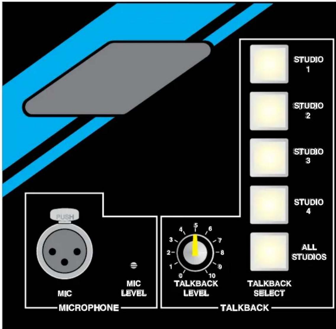
Fig 2-6: Front Panel Talkback Switches & Mic Input.
Note : A standard talkback panel is available for insertion into the Sonifex Sovereign mixer which has five talkback switches for communication with 3 other studios, all studios or the Station Master unit.
Delay and Dump Control
Station Master can be used to control a single profanity delay unit from the multiple studios connected to it. Please note that Station Master does not actually contain a profanity delay.
The unit has two relay controls, Delay and Dump, which should be connected to the profanity unit from the 9 pin D-type on the rear of the Station Master.
Each studio should then be connected to a Dump and Delay switch mounted on the mixing console. For each studio, connect Dump and Delay switches to pins 4 and 5 respectively of the "Controls In/Out" connectors. Pins 17 and 18 can be used to power the Dump and Delay lamps respectively.
In the following description of operation, it is assumed that a sampling profanity delay unit is used which uses digital audio techniques to build up a delay of several seconds which can be dumped all at once, or in several steps.
When a presenter enters a studio and wants to operate in delay, he should ensure that the Delay lamp is illuminated. If it isn't, then the Delay button should be pressed. When the Delay button is pressed in a studio, a permanent contact closure is enabled between the Station Master and the delay unit and the Delay lamp illuminates. This indicates that the delay unit has been primed (however, it may be some time before the delay has actually been built up to the full quoted duration - see your delay unit's technical literature). Pressing the Delay button again will take the delay unit out of operation
If the presenter wants to dump the current on-air audio (for example, if a telephone caller starts swearing), he should press the Dump button. When the Dump button is pressed, a 0.5 second pulse is sent to the Dump input of the profanity delay, so that the current broadcast is discarded (the amount of audio discarded is controlled by your profanity delay). The Dump lamp illuminates for 0.5 seconds while this is happening. The presenter is then immediately live as if the telephone caller had never sworn!
Note : The switch panel which operates with the Sonifex S2 mixer (S2-MTBS) has Delay/ Dump switch controls built into it.
External Inputs
Routing Of External Inputs
The Station Master can accept four stereo balanced inputs which can be distributed to all of the four studios independently. To connect the external sources, use the following connectors :
Audio inputs to the Station Master should be wired to the "External Inputs" connector on the far left of the unit (looking at it from the rear). Phase, non-phase and screen connections are provided for both left and right signals of each input.
Audio outputs to each studio are found on Pins 5 - 12 and Pins 18 - 25 on each of the Audio In/Out 1 - 4 connectors. They all share a common screen on Pin 13.

2
The levels for each input can be altered by adjusting the small potentiometers hidden beneath the holes on the front panel, underneath the "MONITOR SELECT" buttons for EXT 1 - EXT 4 (See Fig 2-2). You'll need a small flat-blade jeweller's screw driver to turn the potentiometers.
The input range for the input level can be adjusted between +5dB and -16dB.
3 Connection Details
Section 1.3 contains information on standard connector wiring for the XLR's, jacks and D-Type connectors found on the Station Master.
Audio Connections
The 25 pin D-Type male (plug) audio connectors marked "AUDIO IN/OUT 1 - 4" are mounted vertically on the rear panel below the "CONTROLS IN/OUT 1 - 4" connectors. All of them have the same connection details.


Audio In/Out 1 - 4
| Pin No. | Audio In/Out 1 - 4 |
| 1 | TRX Left Phase input |
| 2 | TRX Right Phase input |
| 3 | Last Studio to Offer Left Phase output |
| 4 | Last Studio to Offer Right Phase output |
| 5 | External 1 Left Phase output |
| 6 | External 1 Right Phase output |
| 7 | External 2 Left Phase output |
| 8 | External 2 Right Phase output |
| 9 | External 3 Left Phase output |
| 10 | External 3 Right Phase output |
| 11 | External 4 Left Phase output |
| 12 | External 4 Right Phase output |
| 13 | 0 Volts Analog (Screen) |
| 14 | TRX Left Non-Phase input |
| 15 | TRX Right Non-Phase input |
| 16 | Last Studio to Offer Left Non-Phase output |
| 17 | Last Studio to Offer Right Non-Phase output |
| 18 | External 1 Left Non-Phase output |
| 19 | External 1 Right Non-Phase output |
| 20 | External 2 Left Non-Phase output |
| 21 | External 2 Right Non-Phase output |
| 22 | External 3 Left Non-Phase output |
| 23 | External 3 Right Non-Phase output |
| 24 | External 4 Left Non-Phase output |
| 25 | External 4 Right Non-Phase output |
| Case (Mounted on chassis) | |
Studio Controls
The Studio Control connectors are 25 pin D-Type female (socket) connectors mounted vertically below the studio numbers 1 to 4 (1 to 2 for the SM24 model).
Note : the talkback connections for each studio's control connector are different, so please ensure that you are careful when using the details below.
Controls In/Out 1 & 2
Pins 2 - 10 are momentary make to 0V common Pin 14
Pins 15 - 22 are all open collector to 0V, current sink outputs
| Pin No. | Controls In/Out 1 Controls In/Out 2 | |
| 1 Volts | +15V Volts +15V | |
| 2 Offer Switch Offer Switch | ||
| 3 Accept Switch Accept Switch | ||
| 4 Delay Switch Delay Switch | ||
| 5 Dump Switch Dump Switch | ||
| 6 T/B | Switch to studio 2 T/B Switch to studio 1 | |
| 7 T/B | Switch to studio 3 T/B Switch to studio 3 | |
| 8 T/B | Switch to studio 4 T/B Switch to studio 4 | |
| 9 T/B | Switch to Station Master T/B Switch to Station Master | |
| 10 T/B | Switch All T/B Switch All | |
| 11 0 Volts Analog (Audio Common) 0 Volts Analog (Audio Common) | ||
| 12 T/B | Audio output to Studio 1 T/B Audio output to Studio 2 | |
| 13 T/B | Control output to Studio 1 T/B Control output to Studio 2 | |
| 14 | 0 Volts common | 0 Volts common |
| 15 Offer Lamp | Offer Lamp | |
| 16 Accept Lamp | Accept Lamp | |
| 17 Delay Lamp | Delay Lamp | |
| 18 Dump Lamp | Dump Lamp | |
| 19 T/B | Lamp for studio 2 switch T/B Lamp for studio 1 switch | |
| 20 T/B | Lamp for studio 3 switch T/B Lamp for studio 3 switch | |
| 21 T/B | Lamp for studio 4 switch T/B Lamp for studio 4 switch | |
| 22 T/B | Lamp for Station Master switch T/B Lamp for Station Master switch | |
| 23 T/B | Audio input from Studio 1 T/B Audio input from Studio 2 | |
| 24 0 Volts Analog (Audio Common) 0 Volts Analog (Audio Common) | ||
| 25 0 Volts Analog (Audio Common) 0 Volts Analog (Audio Common) | ||
| Case | (Mounted on chassis) N/C | N/C (Mounted on chassis) |


Controls In/Out 3 & 4
Pins 2 - 10 are momentary make to 0V common Pin 14
Pins 15 - 22 are all open collector to 0V, current sink outputs
| Pin No. | Controls In/Out 3 Controls In/Out 4 | |
| 1 Volts | +15V Volts +15V | |
| 2 Offer Switch Offer Switch | ||
| 3 Accept Switch Accept Switch | ||
| 4 Delay Switch Delay Switch | ||
| 5 Dump Switch Dump Switch | ||
| 6 T/B | Switch to studio 1 T/B Switch to studio 1 | |
| 7 T/B | Switch to studio 2 T/B Switch to studio 2 | |
| 8 T/B | Switch to studio 4 T/B Switch to studio 3 | |
| 9 T/B | Switch to Station Master T/B Switch to Station Master | |
| 10 T/B | Switch All T/B Switch All | |
| 11 0 Volts Analog (Audio Common) 0 Volts Analog (Audio Common) | ||
| 12 T/B | Audio output to Studio 3 T/B Audio output to Studio 4 | |
| 13 T/B | Control output to Studio 3 T/B Control output to Studio 4 | |
| 14 | 0 Volts common | 0 Volts common |
| 15 Offer Lamp | Offer Lamp | |
| 16 Accept Lamp | Accept Lamp | |
| 17 Delay Lamp | Delay Lamp | |
| 18 Dump Lamp | Dump Lamp | |
| 19 T/B | Lamp for studio 1 switch T/B Lamp for studio 1 switch | |
| 20 T/B | Lamp for studio 2 switch T/B Lamp for studio 2 switch | |
| 21 T/B | Lamp for studio 4 switch T/B Lamp for studio 3 switch | |
| 22 T/B | Lamp for Station Master switch T/B Lamp for Station Master switch | |
| 23 T/B | Audio input from Studio 3 T/B Audio input from Studio 4 | |
| 24 0 Volts Analog (Audio Common) 0 Volts Analog (Audio Common) | ||
| 25 0 Volts Analog (Audio Common) 0 Volts Analog (Audio Common) | ||
| Case | (Mounted on chassis) | (Mounted on chassis) |
Transmission Outputs
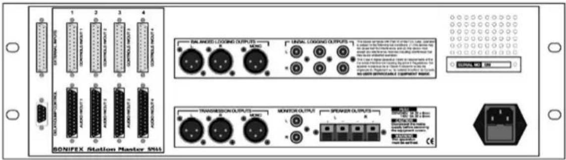
There are three XLR 3 pin plugs used for the electronically balanced transmission outputs. The transmission output is simultaneously fed to both the stereo (LR) and mono outputs. Usually, these outputs will be connected to a processor/limiter before the signal is sent to the transmitter. The connectors have the following pin details:
| Pin No. Transmission Outputs | |
| 1 Screen | |
| 2 Phase | |
| 3 Non-phase | |
Logging Outputs
Balanced Logging Outputs
There are three XLR 3 pin plugs used for the electronically balanced logging outputs. The station output is simultaneously fed to both the stereo (LR) and mono outputs, so that a professional logging machine such as the Sonifex Net-Log can be used to log the station output. The connectors have the following pin details:
| Pin No. Balanced Logging Outputs | |
| 1 Screen | |
| 2 Phase | |
| 3 Non-phase | |
Unbalanced Logging Outputs
The unbalanced phono logging outputs are useful for connecting to domestic logging machines, such as to DVD recorders. Three outputs have been provided so that three DVD-Rs can be used to record a longer duration. The connections are :
| Pin No. Unbalanced Logging Outputs | |
| Tip Phase | |
| Ring Non-phase | |

3
STATION MASTER CONNECTION DETAILS
Station Master

Other Connectors
Mains Power
IEC Connector
Delay/Dump Control
The 9 Pin D-Type male (plug) connector provides the outputs for controlling a profanity delay :
| Pin No. Delay/Dump Control | |
| 1 Ground | |
| 2 N/C | |
| 3 Delay relay contact, normally closed | |
| 4 Dump relay, common contact | |
| 5 Dump relay contact, normally open | |
| 6 N/C | |
| 7 Delay relay, common contact | |
| 8 Delay relay contact, normally open | |
| 9 Dump relay contact, normally closed | |
External Inputs
The 25 pin D-Type female (socket) connector provides the stereo balanced inputs for the four external sources, with the following pins used :
| Pin No. External Inputs | |
| 1 Left phase input EXT 1 | |
| 2 Left chassis ( screen ) input EXT 1 | |
| 3 Right non-phase input EXT 1 | |
| 4 Left phase input EXT 2 | |
| 5 Left chassis ( screen ) input EXT 2 | |
| 6 Right non-phase input EXT 2 | |
| 7 Left phase input EXT 3 | |
| 8 Left chassis ( screen ) input EXT 3 | |
| 9 Right non-phase input EXT 3 | |
| 10 Left phase input EXT 4 | |
| 11 Left chassis ( screen ) input EXT 4 | |
| 12 Right non-phase input EXT 4 | |
| 13 N/C | |
| 14 Left non-phase input EXT 1 | |
| 15 Right phase input EXT 1 | |
| 16 Right chassis ( screen ) input EXT 1 | |
| 17 Left non-phase input EXT 2 | |
| 18 Right phase input EXT 2 | |
| 19 Right chassis ( screen ) input EXT 2 | |
| 20 Left non-phase input EXT 3 | |
| 21 Right phase input EXT 3 | |
| 22 Right chassis ( screen ) input EXT 3 | |
| 23 Left non-phase input EXT 4 | |
| 24 Right phase input EXT 4 | |
| 25 Right chassis ( screen ) input EXT 4 |

3
STATION MASTER CONNECTION DETAILS
Station Master

Monitor Output
The monitor output uses a pair of unbalanced phono connectors for the left and right signal. These should be used if you want to distribute the transmission output through the radio station by connecting these to a power amplifier. The connections are :
| Pin No. Monitor Output | |
| Tip Phase | |
| Ring Non-phase | |
Monitor Insert
The left and right monitor insert connectors are 14 " (6.3mm) jack sockets with the following connections :
| Pin No. Monitor Insert | |
| Tip Phase | |
| Ring Non-phase | |
| Sleeve Screen | |
Speaker Output
The speaker outputs allow you to connect a pair of speakers directly to the Station Master, for use, for example, in the station foyer. The connectors are quick connect spring loaded lever terminals with two holes each for left and right pairs of speaker wires.
Talkback Microphone Input
The talkback microphone input on the front of the Station Master uses an XLR-3 female balanced connector. It has the following connections:
| Pin No. | Talkback Microphone Input |
| 1 Screen | |
| 2 Phase | |
| 3 Non-phase |
We recommend the use of a stub-neck microphone such as those made by Canford Audio (STUB MIC NC, no 53-099).
Headphones
The headphone socket on the front of the Station Master is 14 " (6.3mm) jack socket suitable for driving 600 ohm stereo headphones.
| Pin No. Headphones | |
| Tip Left Out | |
| Ring Right Out | |
| Sleeve Common |

4
STATION MASTER TECHNICAL SPECIFICATION
Station Master

4 Station Master Technical Specification
Inputs/Outputs
Transmission Outputs: Balanced feed-through of transmission inputs via relay contacts.
Mono Output: <75Ω electronically balanced.
Stereo Line Inputs: >20kΩ electronically balanced.
Stereo Line Outputs: <75Ω electronically balanced.
Professional Logging Outputs: <75Ω electronically balanced.
Domestic Logging Outputs: <75Ω unbalanced.
Monitor Speaker Outputs: 10 Watts into 8Ω.
Talkback Mic Input: >1.5kΩ electronically balanced.
Talkback Line Inputs: >10kΩ unbalanced.
Switch Inputs: Momentary closure to common.
Headphone Output: Drives 600 ohm headphones.
Lamp Outputs: Open Collector reference to common, sink 40mA Voltage for lamps is supplied.
Frequency Response
Mic Input: 40Hz to 20kHz at -1dB, +0dB.
Line Inputs: 20Hz to 20kHz at -0.5dB, +0dB.
Noise (20Hz to 20kHz)
Mic Input E.I.N.: -128dB with 200Ω source.
Stereo Line Inputs: -96dB (ref. +8dB)
Connections Summary
For more detail of the connections, please refer to Section 3.
Transmission Outputs: XLR 3 pin male (Balanced).
Mono Output: XLR 3 pin male (Balanced).
Stereo Line External Inputs: 25 pin D-Type plug male.
Studio Line Inputs/Outputs: 25 pin D-Type plug male.
Studio Talkback & Controls: 25 pin D-Type socket female.
Talkback Mic Input: XLR 3 pin female (Balanced).
Professional Logging Outputs: XLR 3 pin male (Balanced).
Domestic Logging Outputs: Phono sockets.
Monitor Speaker Outputs: Quick connect spring loaded lever terminals.
Headphones: 14 " Stereo jack socket.
Physical Specification
Dimensions: 13.5cm (3U)(H)×48.3cm (19" Rack)(w) × 30cm (D)
Weight: 9.15 kgs
Equipment Type
SM24-VU: Station Master with switching and talkback for 2 studios, VU meters.
SM44-VU: Station Master with switching and talkback for 4 studios, VU meters.
SM24-PPM: Station Master with switching and talkback for 2 studios, PPM meters.
SM44-PPM: Station Master with switching and talkback for 4 studios, PPM meters.
SM2
Add on cards to upgrade from an SM24 to an SM44.

5
TALKBACK INTERCOM INTRODUCTION

natural_image
Close-up of a white electronic device with a black screen and a metallic blade, partially obscured by a purple background (no visible text or symbols)5 Talkback Introduction
Talkback refers to the standard method of communication between broadcast studios. Each studio has either a desktop, a rack-mount, or mixer-mounted intercom, usually containing a row of switch buttons. Each switch buttons connects to another studio when pressed, and routes the presenter audio to it.
There are 4 products in the Sonifex Talkback Intercom range :
TB-6D 6 Way Talkback Intercom, desktop free standing
TB-6R 6 Way Talkback Intercom, 19" rack mounted
TB-SD Station Master Talkback Intercom, desktop free standing
TB-SR Station Master Talkback Intercom, 19" rack mounted
The TB-6D and TB-6R are general talkback interfaces which can be connected together to form a talkback system. The TB-SD and TB-SR are talkback units which only operate when connected to the Sonifex Station Master studio switcher.
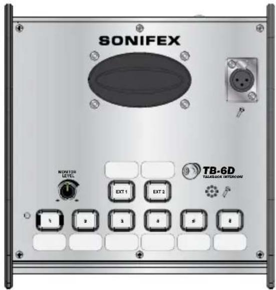
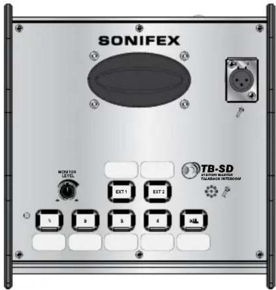
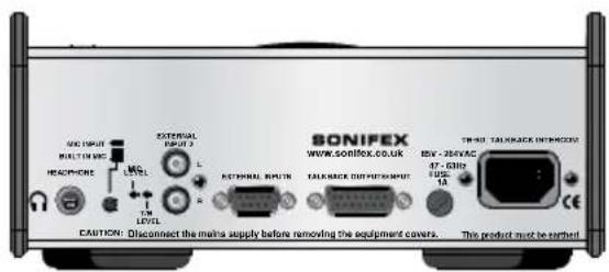
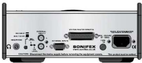
Fig 5-1: TB-6D Talkback Intercom 6 Way Desktop & TB-SD Talkback Intercom Station Master Desktop.
natural_image
Front panel of an electronic device with ports and a knob (no visible text or symbols)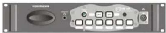
natural_image
Front panel of a computer interface with buttons and ports (no readable text or symbols)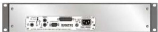
natural_image
Front view of a beige electronic device rear panel with ports and connectors (no visible text or symbols)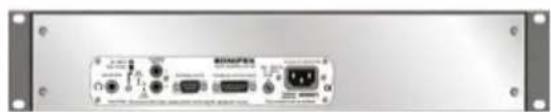
natural_image
Front view of a Siemens 3.02 microcontroller with ports and indicator lights (no visible text or labels)Fig 5-2: TB-6R Talkback Intercom 6 Way Rack & TB-SR Talkback Intercom Station Master Rack.
TB-6D & TB-6R 6 Way Talkback Intercom Overview
The TB-6D and TB-6R are used for general talkback between studios and use DC signalling, also known as ground lifting or ground signalling, to communicate with each other. These units can be installed in various locations throughout a studio complex and linked to one another, with each unit being able to talkback to up to 6 others connected together. Most other talkback systems in general operation also use DC signalling, so you should be able to add these units into an existing installation.
The TB-6D and TB-6R are identical in operation, with the TB-6D used for desktop operation and the TB-6R available as a 2U rack-mount, for use for example, in a central apparatus room or central technical area.
Up to 7 locations or studios can communicate with each other. On each panel, there are 6 front panel buttons for talkback selection and 2 for external inputs. While a button is pressed, the button lights up and the talkback is active to that location.
The buttons work with both a momentary and latched operation. If you simply press the button, talkback will be on and can be cancelled by pressing the button again. If you press and hold the button, the selection is cancelled when released. So, if you wanted to listen to an external input, such as the radio station feed, or off-air monitor, you could simply press the EXT 1 button. If you press a talkback button when the external input buttons are also pressed, the external inputs can be either muted or mixed, depending on the setting of an internal jumper.
The talkback outputs and input are balanced signals on a 15-way male 'D' type plug and the talkback input can be adjusted from -28dB to 9dB using a rear panel preset pot.
You can speak to the separate locations using the onboard front-panel electret mic or there is a separate external mic input on 3 pin XLR female, into which you can plug a suitable gooseneck microphone. There is a rear panel switch to select between the electret and separate input mic. The mic input gain range is adjustable via a rear panel preset pot between 74dB and 53dB.
The unit can monitor two external sources. The EXT 1 input is a balanced stereo input on a rear panel 9 pin D-type socket. The EXT 2 input is an unbalanced stereo input on the 9 pin D-type socket as well as dual phono sockets. EXT 1 is useful for monitoring a distributed signal, such as a radio tuner off-air feed, or an outside source routed from an ISDN codec. EXT 2 is useful for monitoring a local source, such as a portable minidisc/flashcard recorder/player, or the unbalanced soundcard output from a PC editing/playback package.
If you already use a mixer which has a talkback input and output, or continuous talkback output, or just a line level output which you want to use, by changing internal jumpers the intercom can be configured to use these connections instead of the on-board microphone and speaker/headphones. For example, if you have a mic channel on a mixer assigned to talkback and the presenter is using headphones for monitoring the mixer talkback, the Talkback Intercom can be used purely for talkback switching and for monitoring external inputs.

natural_image
Close-up of a white electronic device with a black circular button and a metallic blade, partially obscured by a light overlay (no visible text or symbols)5 TALKBACK INTERCOM INTRODUCTION

natural_image
Close-up of a white electronic device with a black screen and a metallic blade, no visible text or symbols.For monitoring, you can use either the built-in 1W loudspeaker, or headphones on 6.35mm unbalanced stereo jack. The headphones provide 150mW into 32-600Ω headphones. When the headphones are used, the speaker is automatically muted. Additionally, the monitor speaker can be muted via a remote contact on the 9 pin D-type External Input connector, for example, when used in an area with live microphones. Both monitor and headphone levels are fully adjustable between 60dB and 9dB using the front panel volume control.
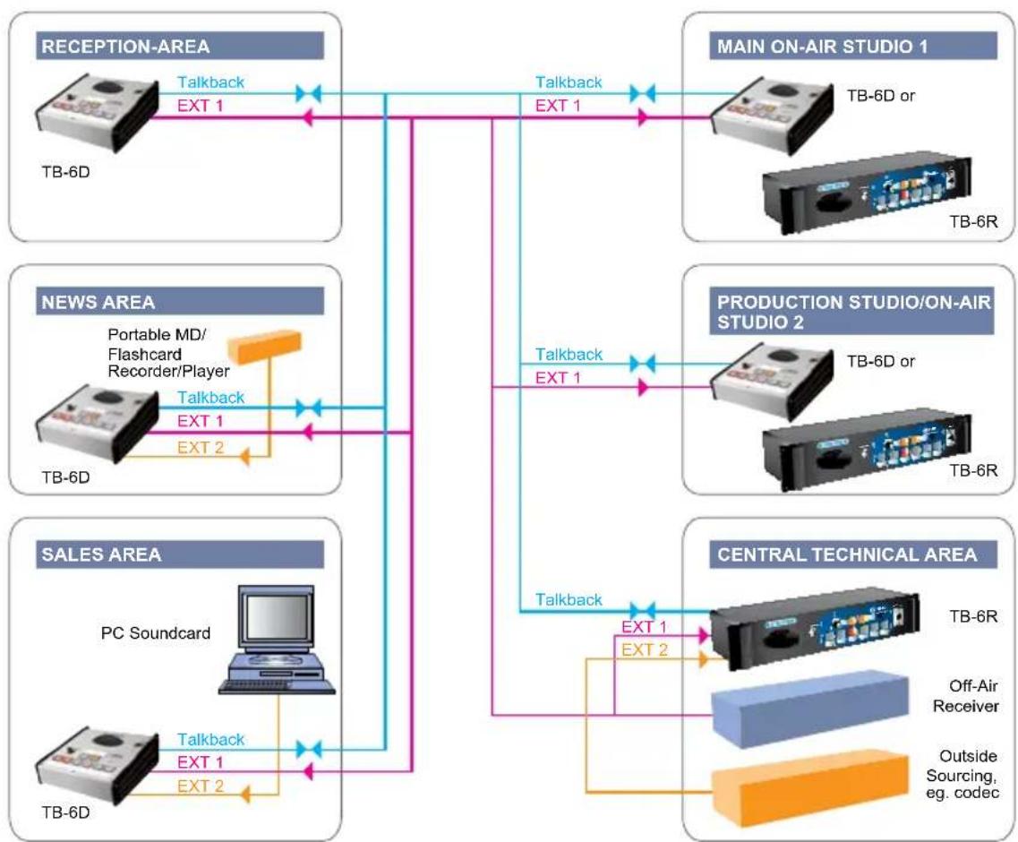
Example Application For TB-6D & TB-6R
A typical application would be to distribute talkback and audio feeds around a radio or TV studio complex, as in this diagram.
flowchart
graph TD
    subgraph RECEPTION_AREA
        A["TB-6D"] -->|Talkback EXT 1| B["Talkback"]
        B --> C["EXT 1"]
    end

    subgraph MAIN_ON_AIR_STUDIO_1
        D["TB-6D or TB-6R"] --> E["Talkback"]
        E --> F["EXT 1"]
    end

    subgraph NEWS_AREA
        G["TB-6D"] --> H["Portable MD/Flashcard Recorder/Player"]
        H --> I["Talkback EXT 1"]
        I --> J["EXT 2"]
    end

    subgraph PRODUCTION_STUDIO_ON_AIR_STUDIO_2
        K["TB-6D or TB-6R"] --> L["Talkback"]
        L --> M["EXT 1"]
    end

    subgraph SALES_AREA
        N["PC Soundcard"] --> O["Talkback EXT 1"]
        O --> P["EXT 2"]
    end

    subgraph CENTRAL_TECHNICAL_AREA
        Q["TB-6R"] --> R["Off-Air Receiver"]
        R --> S["Outside Sourcing, eg. codec"]
        S --> T["Talkback"]
        T --> U["EXT 1"]
        U --> V["EXT 2"]
    end

    RECEPTION_AREA -->|Talkback EXT 1| MAIN_ON_AIR_STUDIO_1
    NEWS_AREA -->|Talkback EXT 1| MAIN_ON_AIR_STUDIO_1
    SALES_AREA -->|Talkback EXT 1| MAIN_ON_AIR_STUDIO_1
Fig 5-3: Example Application For TB-6D & TB-6R.
The TB-6D and TB-6R units are daisy-chained from together from location to location and the radio station output from an off-air receiver is distributed on input EXT 1 of each unit. The EXT 2 input could be used in the news or sales area for monitoring local sources such as a PC audio output. Linking the studios in this way allows all locations to talk to each other together with the ability to monitor 2 external feeds, with independent control of monitor muting and headphone/speaker levels.
TB-SD & TB-SR Station Master Talkback Intercom Overview
These units are used for interfacing with the Sonifex Station Master studio switcher and are similar to the 6 way talkback intercoms, except that the talkback routing and switching (DC signalling) is handled by the Station Master.
All of the features regarding level control, use of the microphone, speaker, headphones, volume control and external inputs are the same as for the TB-6D and TB-6R intercoms. However, the TB-SD and TB-SR can be used to communicate with up to 4 other locations (including the Station Master), or all of the locations by pressing the "ALL" button.
Whereas the TB-6D and TB-6R have talkback outputs and input on a 15-way male 'D' type plug, the TB-SD and TB-SR have instead a remotes socket consisting of a 25-way female 'D' type. This contains switch and indicator controls for the 4 talkback buttons together with power and talkback input/output/control lines to and from the Station Master.
Example Application For TB-SD & TB-SR
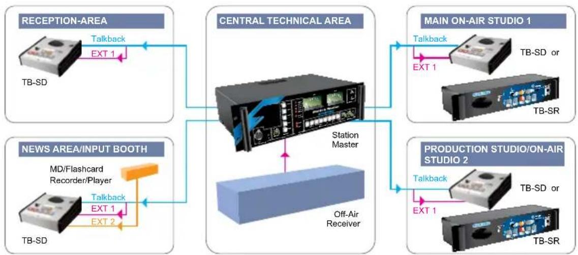
Using the Station Master as the core of a complete studio air-switching, distribution and talkback system, up to 4 studios can be connected using the TB-SD and TB-SR. A typical application would be to distribute talkback and audio feeds around a small radio station, as in this diagram.
flowchart
graph TD
    A["RECEPTION-AREA"] -->|Talkback EXT 1| B(CENTRAL TECHNICAL AREA)
    C["NEWS AREA/INPUT BOOTH"] -->|Talkback EXT 2| B
    D["MAIN ON-AIR STUDIO 1"] -->|Talkback EXT 1| B
    E["PRODUCTION STUDIO/ON-AIR STUDIO 2"] -->|Talkback EXT 1| B
    B --> F["Station Master"]
    F --> G["Off-Air Receiver"]
    G --> H["TB-SD or TB-SR"]
    B --> I["TB-SD"]
Fig 5-4: Example Application For TB-SD & TB-SR.

natural_image
Close-up of a white electronic device with a screen and antenna, no visible text or symbols5 TALKBACK INTERCOM INTRODUCTION

natural_image
Close-up of a white electronic device with a transparent fan and control buttons, no visible text or symbols.The TB-SD and TB-SR intercoms are connected to the Station Master in a star pattern, with the Station Master as the central hub and unbalanced point-to-point links from it to each location. This setup could also be used for controlling on-air switching and for distribution of the external inputs to the other locations.
Talkback Intercom Benefits
- Provide talkback for up to 7 locations (for TB-6D and TB-6R).
• Brightly lit push-to-talk buttons.
• Momentary or latched buttons.
• Built-in electret microphone, with input for external microphone.
• Monitoring of 2 external inputs, e.g. for off-air receiver.
• Auto muting, or mix, of external inputs. - Integrates with Sonifex S2 mixer and is compatible with other talkback systems.
Following are details on how the Station Master functions.
Station Master Features
Two of the talkback intercoms link to the Sonifex Station Master. This is a 3U rack-mount Sonifex product which combines into a single package all the black boxes required for audio distribution, studio switching, talkback and monitoring for up to 4 studios.
Studio Switching - Station Master accepts stereo audio feeds from up to 4 studios, switching them individually to transmission using offer and accept operation. The output of the current 'on-air' studio is distributed to the other studios via a dedicated bus, avoiding the need for multiple studio distribution links. The output of the Station Master is provided as a stereo pair or a mono feed of the stereo source. The studio switching is achieved using latching relays and therefore retains its switch status in the event of power-failure.
Delay Control - A profanity delay can be controlled by the Station Master allowing you to install just one delay unit that can be shared by your studios and used by the studio currently on air.
Monitoring - The Station Master is fitted with either a pair of true PPM meters, or VU meters, for monitoring up to 8 stereo sources. These sources consist of the connected studios and four external sources such as news feeds or off air receivers. The audio can be monitored via headphones or output through a power amplifier capable of driving 10W into 8Ω speakers. There are also two 14 " jack insert points for using the Station Master to monitor from a jack-field.
Audio Distribution - Station Master distributes the 4 incoming stereo signals to each of the connected studios without the need for external distribution amplifiers. These signals, such as off-air receivers, news feeds and outside broadcasts, can be professional balanced inputs or at domestic unbalanced line levels. The gain of the incoming stereo signals can be adjusted from the front panel. Distribution gain is controlled by a preset potentiometer.
Talkback - The Station Master's talkback system acts as the master station for talkback with 4 satellite systems. These can either be the connected studios or other locations such as a record library or engineering workshop. Individual satellites can talk to each other or broadcast to all stations.
Logging - To allow for logging of broadcasts the Station Master has a stereo balanced output for professional logging equipment, together with 3 sets of phono unbalanced outputs for connection to domestic VCR equipment.
Power Failure - In the event of a power failure to the Station Master, it will continue to route the current on-air studio to the stereo transmission output. Also, when power is re-applied to the Station Master, all switching, including the offer and accept switching, will instantly re-initialise to the configuration when power was lost. This means that your on-air studio can continue transmitting, even if power to the Station Master has failed.

natural_image
Close-up of a white electronic device with a black circular button and a metallic blade, partially obscured by a light overlay (no visible text or symbols)5 TALKBACK INTERCOM INTRODUCTION

natural_image
Close-up of a white electronic device with a black circular button and a metallic blade, against a purple background (no visible text or symbols)Station Master Talkback Operation and Connections
Station Master can route and control the talkback between up to 4 studios and the Station Master itself (i.e. 5 talkback points). Each studio has the ability to have a row of five switch buttons so that the presenter can talk to the other three studios, the Station Master, or all studios, including the Station Master. So, for each studio, you'll need to make the following connections:
Connect the talkback switches to pins 6, 7, 8, 9, and 10 of the "Controls In/Out" connectors. Pins 19, 20, 21 and 22 can be used to power the lamps for the switches. (When the T/B Switch All button is pressed, all four lamps should be illuminated).
Note : The talkback connection details are slightly different for each studio - ensure that you are connecting to the correct studio.
Connect the unbalanced audio input and output signals, together with the T/B control output to the studio :
- The T/B audio input (pin 23 of the "Controls In/Out" connector) should be connected to the talkback output of the mixing desk in the studio.
- The T/B audio output (pin 12 of the "Controls In/Out" connector) should be connected to the talkback input of the mixing desk in the studio.
- The T/B control signal (pin 13 of the "Controls In/Out" connector) should be routed to the talkback control input of the mixing desk. When one of the talkback buttons is pressed in a different studio, the talkback control signal closes to indicate to the mixing desk that a talkback signal is being sent to it. The mixing desk is usually configured to mix the talkback with the presenter's headphones, so that the presenter can hear the talkback being sent from another studio.
On the front of the Station Master are a set of switches for communication with the other studios. There is also a TALKBACK LEVEL control for altering the level of the talkback received from other studios to the in-built speaker.
A microphone can be plugged directly into the front of the Station Master for when sending talkback to other studios. We recommend the use of a standard STUB, or goose-neck, microphone. The level of the microphone can be set by adjusting the MIC LEVEL potentiometer using a small flat-bladed jeweller's screwdriver.
To operate the talkback, simply press and hold the button for the studio that you want to talk to for the duration of your conversation.
Note : A standard talkback panel is available for insertion into the Sonifex S2 mixer which has five talkback switches for communication with 3 other studios, all studios or the Station Master unit.
flowchart
graph TD
    A["1 2 3 4 5 6"] --> B["TB-6D & TB-SR TALKBACK SWITCHES"]
    C["1 2 3 4 ALL"] --> B
    D["TB-6D & TB-SR"] --> E["STATION MASTER REMOTES"]
    F["TALKBACK OUTPUTS/INPUT"] --> G["TRX"]
    H["TRX"] --> I["TRX"]
    J["External INPUTS"] --> K["MUTE"]
    L["VOLUME CONTROL"] --> M["SWITCHING/ROUTING"]
    N["EXT INPUTS MUTE CONTROL"] --> M
    O["T/BACK IN"] --> P["T/BACK CTRL"]
    Q["T/BACK GAIN"] --> P
    R["J1"] --> S["EXT1 EXT2"]
    T["J3"] --> U["T/BACK OUT"]
    V["AGC"] --> W["MIC GAIN"]
    X["EXT MIC"] --> Y["EXCTRET MIC"]
    Z["LETTLE"] --> AA["OUT"]
    AB["LETTLE"] --> AC["OUT"]
    AD["LETTLE"] --> AE["OUT"]
    AF["LETTLE"] --> AG["OUT"]
    AH["LETTLE"] --> AI["OUT"]
    AJ["LETTLE"] --> AK["OUT"]
    AL["LETTLE"] --> AM["OUT"]
    AN["LETTLE"] --> AO["OUT"]

natural_image
Illustration of a stylized house with decorative elements and floating bubbles (no text or symbols)TALBACK INTERFACE INTRODUCTION
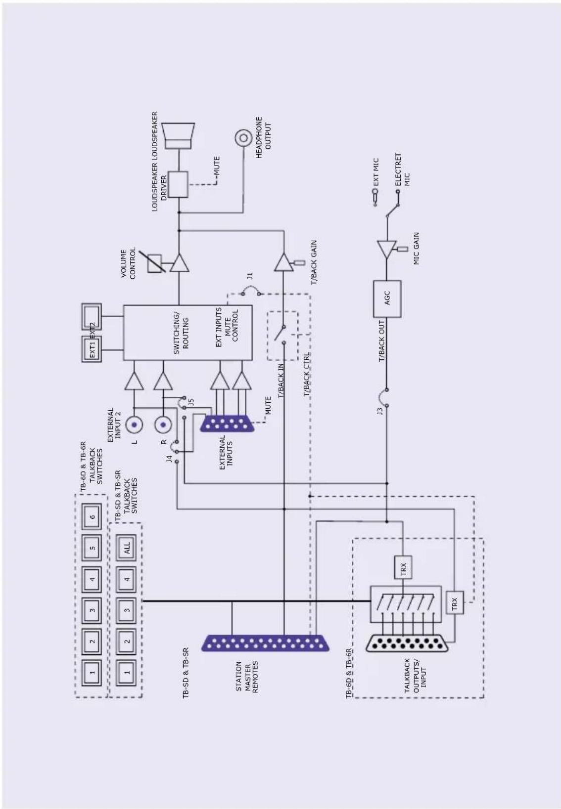
Fig 5-5: Talkback Intercom System Block Diagram.
6
TB-6D & TB-6R TALKBACK INTERCOM CONFIGURATION & CONTROLS


natural_image
Close-up of a white electronic device with a screen and antenna, no visible text or symbols6 TB-6D & TB-6R 6 Way Talkback Intercom Configuration & Controls
Front Panel Control Details
Information about all of the connections and controls located on the front of the TB-6D units. Monitor External
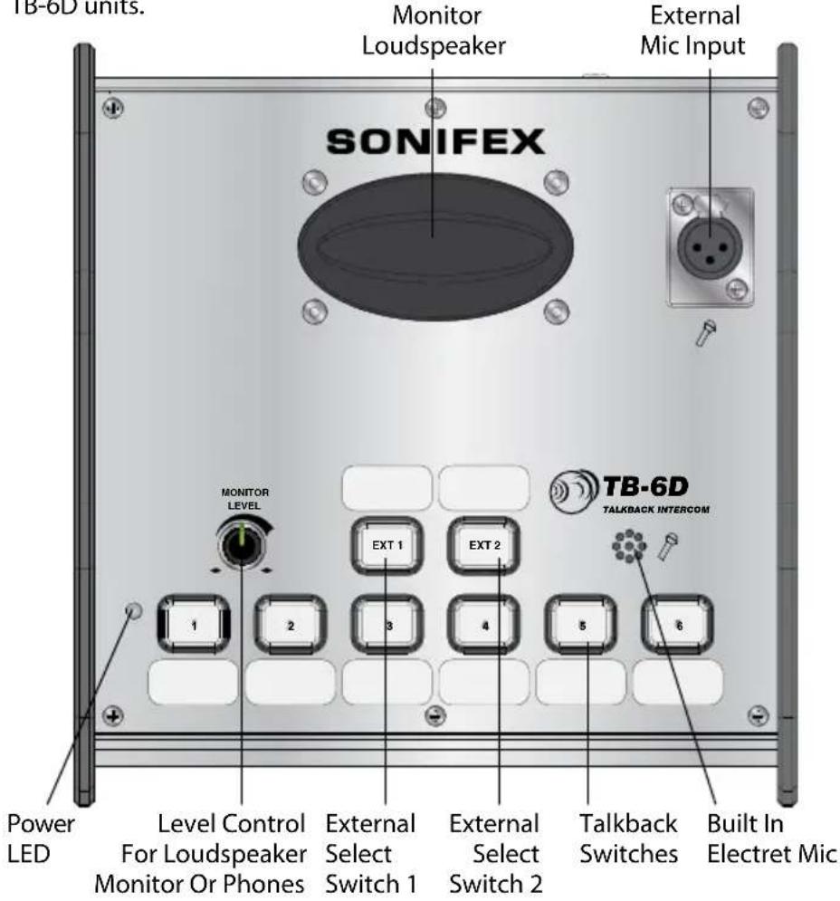
Fig 6-1: TB-6D Front Panel.
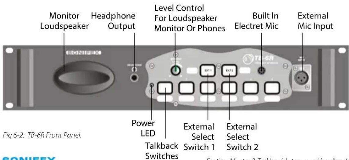
Power LED Indicator
The power LED indicates that the equipment is powered and operational when illuminated.
Level Control for Monitor Loudspeaker and Headphones
This will alter the output level of either the top mounted monitor loudspeaker or the rear mounted headphone output. Plugging in the headphones mutes the loudspeaker output.
External Select Switch 1
This selects and routes external input 1 to the headphones or loudspeaker.
External Select Switch 2
This selects and routes external input 2 to the headphones or loudspeaker.
Talkback Switches
While a button is pressed, the switch is illuminated and the talkback is active to that location. The buttons work with both a momentary and latched operation (* see below). If held down, the selection is cancelled when released, otherwise the button is alternate action. When talkback is active, depending on the setting of Jumper 1, the external inputs can be either muted or mixed.
* When headphones are not inserted, it's not possible to latch the function of talkback switches 1-6. The latch function will function as normal when headphones are inserted. Similarly if the latched function is used with headphones inserted and they are then removed, the unit will default back to non-latched operation.
Built in Electret Microphone
The built in microphone, fitted under the front panel, is used unless the external mic is selected on the rear panel.
Monitor Loudspeaker
There is a 1W mono speaker output to hear talkback and external monitoring. The talkback level is adjustable via the pot on the rear panel. The external input level is set internally. The talkback and EXT 1 and EXT 2 output levels can be adjusted using the front panel level control. The speaker can be muted via a remote on the external input connector when used in an area with live microphones.
External Microphone
The external microphone input is an XLR 3 pin connector on the top panel which allows the fitment of a gooseneck microphone or other standard microphone. Selection for the microphone input type is made on the back panel.
Pin 1: Screen.
Pin 2: Phase.
Pin 3: Non-phase

natural_image
Close-up of a white electronic device with a black circular button and a metallic blade, partially obscured by a light overlay (no visible text or symbols)6
TB-6D & TB-6R TALKBACK INTERCOM CONFIGURATION & CONTROLS

natural_image
Close-up of a white electronic device with a transparent fan and control buttons (no visible text or symbols)TB-6D & TB-6R TALKBACK INTERCOM CONFIGURATION & CONTROLS
Rear Panel Control Details
Information about all of the connections and controls located on the rear of the TB-6D units.
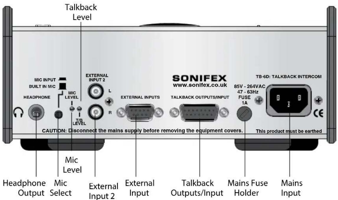
Fig 6-3: TB-6D Rear Panel.
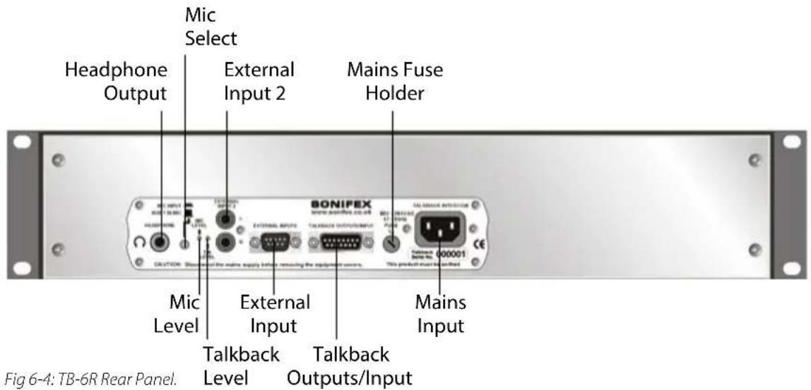
Headphone Output
This is a 6.35mm unbalanced stereo headphone jack providing a stereo audio output, capable of driving 150mW into 32-600Ω headphones. Plugging in the headphones disables the loudspeaker output.
Ring: Right
Tip : Left
Sleeve : Screen
Mic Select
This push-button switch selects the mic input :Switch depressed (down) - External mic selectedSwitch not depressed (up) - Internal mic selected
Adjusting the Microphone Gain Level
The Mic Level Preset Pot controls the level of the mic input signal. Use a jeweller's screwdriver to adjust the gain between 74dB and 53dB.
Adjusting the Talkback Gain Level
The Talkback Level Preset Pot controls the level of the talkback input signal. Use a jeweller's screwdriver to adjust the gain between -28dB and 9dB.
External Input 2
This is a dual phono socket, stereo unbalanced at domestic level in parallel with the 9 way female 'D' type socket. These inputs are not used when pins 4 & 8 on the external inputs connector are configured for talkback.
Inner: Phase
Outer: Screen
External Inputs & Mute Control
This is a 9-way female 'D' type socket used for accepting external inputs and the mute signal. External input 1 is a balanced analogue stereo line level input with an impedance of >40kΩ. Pins 4 & 8 are dual purpose and configured by the internal jumpers. When the pins are used as external input 2, or as talkback input/output they accept an unbalanced analogue stereo domestic level input with an impedance of >30kΩ.
If you already use a mixer which has a talkback input and output, or continuous talkback output, or just a line level output which you want to use, by changing internal jumpers the intercom can be configured to use these connections instead of the on-board microphone and speaker/headphones. For example, if you have a mic channel on a mixer assigned to talkback and the presenter is using headphones for monitoring the mixer talkback, the Talkback Intercom can be used purely for switching and monitoring external inputs. See the later section on “Local/External Talkback” for information on how to do this.
The connector pin-out is as follows;
Pin 1: Talkback control output (active low)
Pin 2: Input 1 left phase
Pin 3: Input 1 right phase
Pin 4: Input 2 left OR Talkback in phase (see jumper settings)
Pin 5: Ground
Pin 6: Input 1 left non-phase
Pin 7: Input 1 right non-phase
Pin 8: Input 2 right OR Talkback out phase (see jumper settings)
Pin 9: Mute control (link to pin 5 for speaker mute)

natural_image
Close-up of a white electronic device with a black circular button and a metallic blade, partially obscured by a light overlay (no visible text or symbols)6 TB-6D & TB-6R TALKBACK INTERCOM CONFIGURATION & CONTROLS

natural_image
Close-up of a white electronic device with a black circular button and a metallic blade, against a purple background (no visible text or symbols)Talkback Input/Outputs
These use a 15-way male 'D' type plug for the six balanced talkback outputs and one balanced talkback input, which all use DC signalling. These can interface with other Sonifex S2 mixer talkback or intercom units as well as talkback panels in some other mixers, or dedicated talkback systems.
The connector pin-out is as follows;
Pin 1: Talkback 1 out phase.
Pin 2: Talkback 2 out phase.
Pin 3: Talkback 3 out phase.
Pin 4: Talkback 4 out phase.
Pin 5: Talkback 5 out phase.
Pin 6: Talkback 6 out phase.
Pin 7: Talkback in phase.
Pin 8: Ground.
Pin 9: Talkback 1 out non-phase.
Pin 10: Talkback 2 out non-phase.
Pin 11: Talkback 3 out non-phase.
Pin 12: Talkback 4 out non-phase.
Pin 13: Talkback 5 out non-phase.
Pin 14: Talkback 6 out non-phase.
Pin 15: Talkback in non-phase.
Fuse Holder
Fitted with a single 1 amp anti-surge fuse.
Mains Input
The power supply is connected via an IEC Connector (85V - 264V, 47-63Hz AC operation).
Internal Jumper Configuration
The talkback intercom can be configured in a number of ways depending on the way in which the jumpers are set. The standard options are;
- Mix or mute external inputs when talkback is active.
- Select local or external (via external inputs connector) talkback.
Summary of Jumper Settings for the Talkback Unit
| Jumper | Set over Pins | Effect |
| J1 | 1 & 2None | External inputs are muted when talkback is activeExternal inputs are mixed when talkback is active |
| J2 - Reserved | ||
| J3 | 1 & 2None | Set when local talkback is usedSet when external talkback is used |
| J4 | 1 & 22 & 3 | Pin 4 on External Inputs connector is external input 2 leftPin 4 on External Inputs connector is talkback input |
| J5 | 1 & 22 & 3 | Pin 8 on External Inputs connector is external input 2 rightPin 8 on External Inputs connector is talkback output |
Note: Options in bold are set as default when shipped.
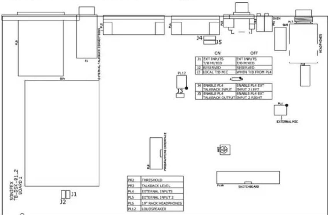
Fig 6-5: TB-6D & TB-6R Board Layout.
6
TB-6D & TB-6R TALKBACK INTERCOM CONFIGURATION & CONTROLS

natural_image
Close-up of a white electronic device with a black circular button and a metallic blade, against a purple background (no visible text or symbols)External Input Muting/Mixing
When the talkback is active, the external inputs can be either muted or mixed to the outputs depending on the jumper settings. With J1 fitted the external inputs are muted when talkback is active. With J1 not fitted the external inputs are mixed with the talkback when active.
Local/External Talkback
The talkback can be either local or external. When J4 is fitted over pins 1 & 2, pin 4 on the external inputs remote connector is configured as external input 2 left. When J4 is fitted over pins 2 & 3, pin 4 on the external inputs remote connector is configured as the talkback input.
In this case, talkback input means the talkback input to the internal system, i.e. it is an actual output on the 9 pin D-type connector, which could be the talkback input to the Sonifex S2 mixer control room monitor channel.
When J5 is fitted over pins 1 & 2, pin 8 on the external inputs remote connector is configured as external input 2 right. When J5 is fitted over pins 2 & 3, pin 8 on the external inputs remote connector is configured as the talkback output.
In this case, the talkback output is to the internal system, but on the connector appears as a talkback input, e.g. when the talkback output comes from another source other than the built in microphone or external microphone connector. This could be, for example, the talkback output from the Sonifex S2 mixer control room monitor channel, or a continuous talkback output from any other mixer.
In this case J3 must also be not fitted, so that the internal mic, or connected mic are not used. If J3 is fitted, the mic will be mixed over the incoming talkback signal.
Below is an example of using the external talkback by connecting the unit to an S2 mixer via the control room monitor module. The following connections are made to the module via the external inputs connector on the rear panel:
Pin 1: Connect to "Ring" on the talkback input jack.
Pin 2: As required.
Pin 3: As required.
Pin 4: Connect to "Tip" on the talkback input jack.
Pin 5: Ground (connect to screens).
Pin 6: As required.
Pin 7: As required.
Pin 8: Connect to "Tip" on the talkback output jack.
Pin 9: As required.
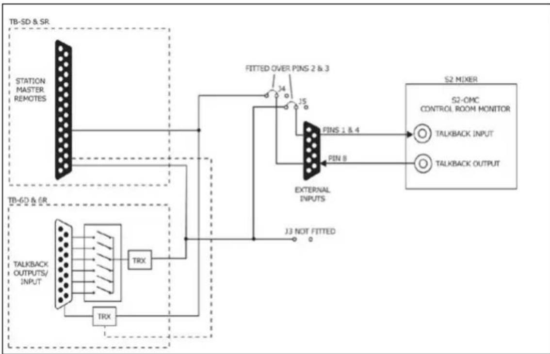
flowchart
graph TD
    A["TB-SD & SR"] --> B["STATION MASTER REMOTES"]
    B --> C["FITTED OVER PINS 2 & 3"]
    C --> D["S2 MIXER"]
    D --> E["S2-CMC CONTROL ROOM MONITOR"]
    D --> F["TALKBACK INPUT"]
    D --> G["TALKBACK OUTPUT"]
    H["TB-6D & 6R"] --> I["TALKBACK OUTPUTS/INPUT"]
    I --> J["TRX"]
    J --> K["External INPUTS"]
    K --> L["J3 NOT FITTED"]
    M["TRX"] --> N["External INPUTS"]
    O["External INPUTS"] --> P["PINS 1 & 4"]
    P --> Q["S2 MIXER"]
Fig 6-6: Connecting The Talkback Intercom To The Sonifex S2 Mixer Output Module (S2-OMC).

natural_image
Close-up of a white electronic device with a transparent screen and control buttons, no visible text or symbols.
natural_image
Close-up of a white electronic device with a black circular top and a metallic blade, partially visible against a purple background (no text or symbols)TB-6D & TB-6R TALKBACK INTERCOM CONFIGURATION & CONTROLS
TB6 Interconnection Wiring Diagram Example Situations
This configuration applies to TB-6D, TB-6R, S2-TBS units.
If the TB-6D or TB-6R units are to be used in a live microphone situation, the mute signals (pins 5 & 9) on the external inputs connector must be connected to the relevant mic live mute controls signals.
Studio 1

Studio 2
Racks Room
News Booth
Sales Office
Reception
News Room

Fig 6-7: Interconnection Diagram.
7 TB-SD & TB-SR Station Master Talkback Intercom Configuration & Controls
Front Panel Control Details
Information about all of the connections and controls located on the front of the
TB-SD units.
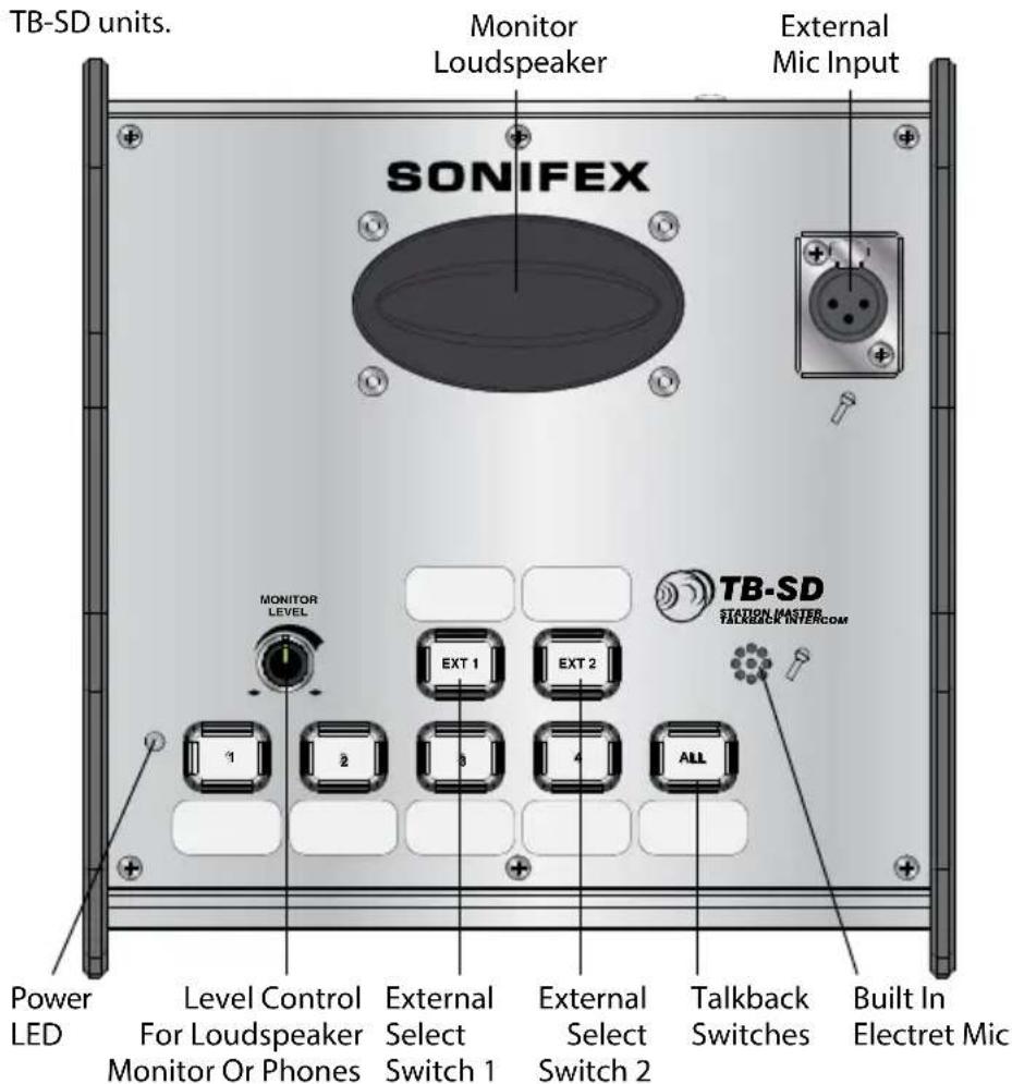
Fig 7-1: Front Panel Controls for TB-SD.
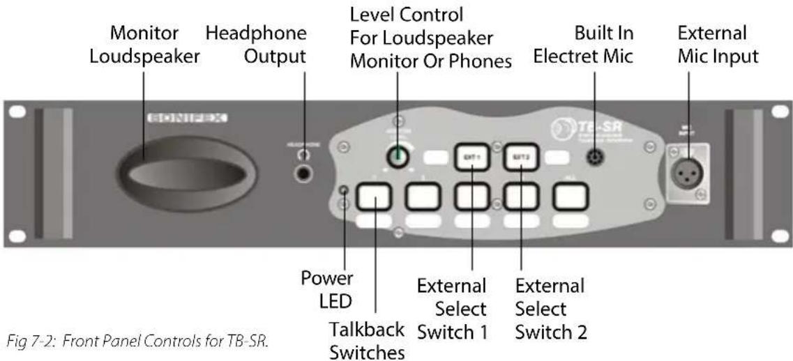

natural_image
Close-up of a smartphone screen with abstract UI elements and a circular icon (no readable text or symbols)7 TB-SD & TB-SR STATION MASTER TALKBACK INTERCOM CONFIGURATION & CONTROLS

natural_image
Close-up of a white electronic device with a transparent fan and control buttons, no visible text or symbols.Power LED Indicator
The power LED indicates that the equipment is powered and operational when illuminated.
Level Control for Monitor Loudspeaker and Headphones
This will alter the output level of either the top mounted monitor loudspeaker or the rear mounted headphone output. Plugging in the headphones will disable the loudspeaker output.
External Select Switch 1
This selects and routes external input 1 to the headphones or loudspeaker.
External Select Switch 2
This selects and routes external input 2 to the headphones or loudspeaker.
Talkback Switches
While a button is pressed, the switch is illuminated and the talkback is active to that location. The "ALL" button allows talkback to all 4 of the locations. The buttons work with both a momentary and latched operation. If held down, the selection is cancelled when released, otherwise the button is alternate action. When talkback is active, depending on the setting of Jumper 1, the external inputs can be either muted or mixed.
Built in Electret Microphone
The built in microphone, fitted under the front panel, is used unless the external mic is selected on the rear panel.
Monitor Loudspeaker
There is a 1W mono speaker output to hear talkback and external monitoring. The talkback level is adjustable via the pot on the rear panel. The external input level is set internally.
The talkback and EXT 1 and EXT 2 output levels can be adjusted using the front panel level control. The speaker can be muted via a remote on the external input connector when used in an area with live microphones.
External Microphone
The external microphone input is an XLR 3 pin connector on the top panel which allows the fitment of a gooseneck microphone or other standard microphone. Selection for the microphone input type is made on the back panel.
Pin 1: Screen.
Pin 2: Phase.
Pin 3: Non-phase
Rear Panel Control Details
Information about all of the connections and controls located on the rear of the TB-SD units.
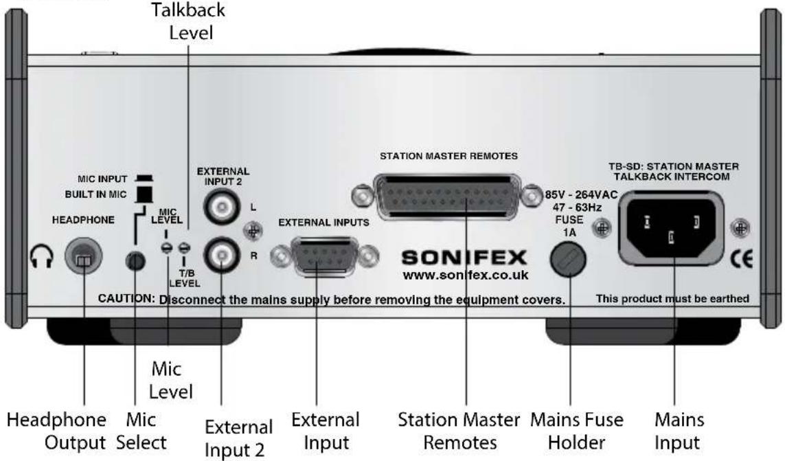
Fig 7-3: TB-SD Rear Panel.
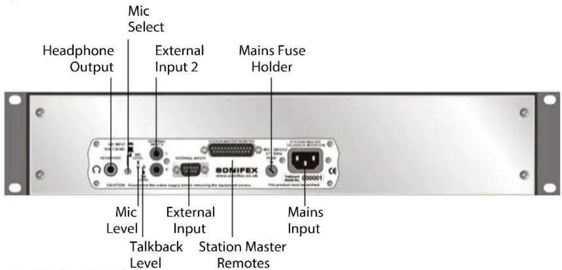
Fig 7-4: TB-SR Rear Panel.
Headphone Output
This is a 6.35mm unbalanced stereo headphone jack providing a stereo audio output, capable of driving 150mW into 32-600Ω headphones. Plugging in the headphones disables the loudspeaker output.
Ring: Right
Tip : Left
Sleeve: Screen

natural_image
Close-up of a smartphone screen with a white abstract graphic overlay (no readable text or symbols)7 TB-SD & TB-SR STATION MASTER TALKBACK INTERCOM CONFIGURATION & CONTROLS

natural_image
Close-up of a white electronic device with a transparent fan and control buttons, no visible text or symbols.Mic Select
This push-button switch selects the mic input :
Switch depressed (down) - External mic selected
Switch not depressed (up) - Internal mic selected
Adjusting the Microphone Gain Level
The Mic Level Preset Pot controls the level of the mic input signal. Use a jeweller's screwdriver to adjust the gain between 74dB and 53dB.
Adjusting the Talkback Gain Level
The Talkback Level Preset Pot controls the level of the talkback input signal. Use a jeweller's screwdriver to adjust the gain between -28dB and 9dB.
External Input 2
This is a dual phono socket, stereo unbalanced at domestic level in parallel with the 9 way female 'D' type socket. These inputs are not used when pins 4 & 8 on the external inputs connector are configured for talkback.
Inner: Phase
Outer: Screen
External Inputs & Mute Control
This is a 9-way female 'D' type socket used for accepting external inputs and the mute signal. External input 1 is a balanced analogue stereo line level input with an impedance of >40k . Pins 4 & 8 are dual purpose and configured by the internal jumpers. When the pins are used as external input 2, or as talkback input/output they accept an unbalanced analogue stereo domestic level input with an impedance of >30k .
If you already use a mixer which has a talkback input and output, or continuous talkback output, or just a line level output which you want to use, by changing internal jumpers the intercom can be configured to use these connections instead of the on-board microphone and speaker/headphones. For example, if you have a mic channel on a mixer assigned to talkback and the presenter is using headphones for monitoring the mixer talkback, the Talkback Intercom can be used purely for switching and monitoring external inputs. See the later section on "Local/External Talkback" for information on how to do this.
The connector pin-out is as follows;
Pin 1: Talkback control output (active low)
Pin 2: External input 1 left phase
Pin 3: External input 1 right phase
Pin 4: External input 2 left OR Talkback in phase (see jumper settings)
Pin 5: 0V Analogue (Input 2 Common)
Pin 6: External input 1 left non-phase
Pin 7: External input 1 right non-phase
Pin 8: External input 2 right OR Talkback out phase (see jumper settings)
Pin 9: Mute control (link to pin 1 for speaker mute)
Station Master Remotes
This is a 25-way female 'D' type socket used for connecting to the Talkback connector on a Sonifex Station Master. The connector pin-out is as follows:
Pin 1: +15V Input from Station Master (indicator supply)
Pin 2: N/C.
Pin 3: N/C.
Pin 4: N/C.
Pin 5: N/C.
Pin 6: Talkback 1 switch.
Pin 7: Talkback 2 switch.
Pin 8: Talkback 3 switch.
Pin 9: Talkback 4 switch.
Pin 10: Talkback all switch.
Pin 11:0V Analogue (audio common).
Pin 12: Talkback input from Station Master talkback out.
Pin 13: Talkback control input.
Pin 14: 0V Analogue (switch common).
Pin 15: N/C.
Pin 16: N/C.
Pin 17: N/C.
Pin 18: N/C.
Pin 19: Talkback 1 indicator.
Pin 20: Talkback 2 indicator.
Pin 21: Talkback 3 indicator.
Pin 22: Talkback 4 indicator.
Pin 23: Talkback output to Station Master talkback input.
Pin 24: 0V Analogue (audio common).
Pin 25: 0V Analogue (audio common).
Fuse Holder
Fitted with a single 1 amp anti-surge fuse
Mains Input
The power supply is connected via an IEC Connector (85V - 264V, 47-63Hz AC operation).

natural_image
Close-up of a white electronic device with a black circular button and a metallic blade, partially overlaid by a light blue background (no visible text or symbols)7
TB-SD & TB-SR STATION MASTER TALKBACK INTERCOM CONFIGURATION & CONTROLS

natural_image
Close-up of a handheld device with a screen and antenna, no visible text or symbolsTB-SD & TB-SR STATION MASTER TALKBACK INTERCOM CONFIGURATION & CONTROLS
Internal Jumper Configuration
The Talkback Intercom can be configured in a number ways depending on the way in which the jumpers are set. The standard options are;
- Mix or mute external inputs when talkback is active.
- Local or external (via external inputs connector) talkback.
Summary of Jumper Settings for the Talkback Unit
| Jumper | Set over Pins | Effect |
| J1 | 1 & 2None | External inputs are muted when talkback is activeExternal inputs are mixed when talkback is active |
| J2 - Reserved | ||
| J3 | 1 & 2None | Set when local talkback is usedSet when external talkback is used |
| J4 | 1 & 22 & 3 | Pin 4 on External Inputs connector is external input 2 leftPin 4 on External Inputs connector is talkback input |
| J5 | 1 & 22 & 3 | Pin 8 on External Inputs connector is external input 2 rightPin 8 on External Inputs connector is talkback output |
Note: Options in bold are set as default when shipped.
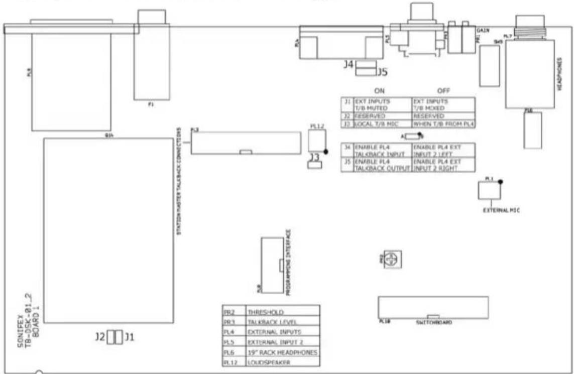
Fig 7-5: TB-SD & TB-SR Board Layout.
External Input Muting/Mixing
When the talkback is active the external inputs can be either muted or mixed to the outputs depending on the jumper settings. With J1 fitted the external inputs are muted when talkback is active. With J1 not fitted the external inputs are mixed with the talkback when active.
Local/External Talkback
The talkback can be either local or external. When J4 is fitted over pins 1 & 2, pin 4 on the external inputs remote connector is configured as external input 2 left. When J4 is fitted over pins 2 & 3, pin 4 on the external inputs remote connector is configured as the talkback input.
In this case, talkback input means the talkback input to the internal system, i.e. it is an actual output on the 9 pin D-type connector, which could be the talkback input to the Sonifex S2 mixer control room monitor channel.
When J5 is fitted over pins 1 & 2, pin 8 on the external inputs remote connector is configured as external input 2 right. When J5 is fitted over pins 2 & 3, pin 8 on the external inputs remote connector is configured as the talkback output.
In this case, the talkback output is to the internal system, but on the connector appears as a talkback input, e.g. when the talkback output comes from another source other than the built in microphone or external microphone connector. This could be, for example, the talkback output from the Sonifex S2 mixer control room monitor channel, or a continuous talkback output from any other mixer.
In this case J3 must also be not fitted, so that the internal mic, or connected mic are not used. If J3 is fitted, the mic will be mixed over the incoming talkback signal.
Below is an example of using the external talkback by connecting the unit to an S2 mixer via the control room monitor module. The following connections are made to the module via the external inputs connector on the rear panel:
Pin 1: Connect to "Ring" on the talkback input jack.
Pin 2: As required.
Pin 3: As required.
Pin 4: Connect to "Tip" on the talkback input jack.
Pin 5: Ground (connect to screens).
Pin 6: As required.
Pin 7: As required.
Pin 8: Connect to "Tip" on the talkback output jack.
Pin 9: As required.

natural_image
Close-up of a white electronic device with a black circular button and a metallic blade, against a purple background (no visible text or symbols)7 TB-SD & TB-SR STATION MASTER TALKBACK INTERCOM CONFIGURATION & CONTROLS

natural_image
Close-up of a white electronic device with a transparent blade and control buttons, no visible text or symbols.TB-SD & TB-SR STATION MASTER TALKBACK INTERCOM CONFIGURATION & CONTROLS
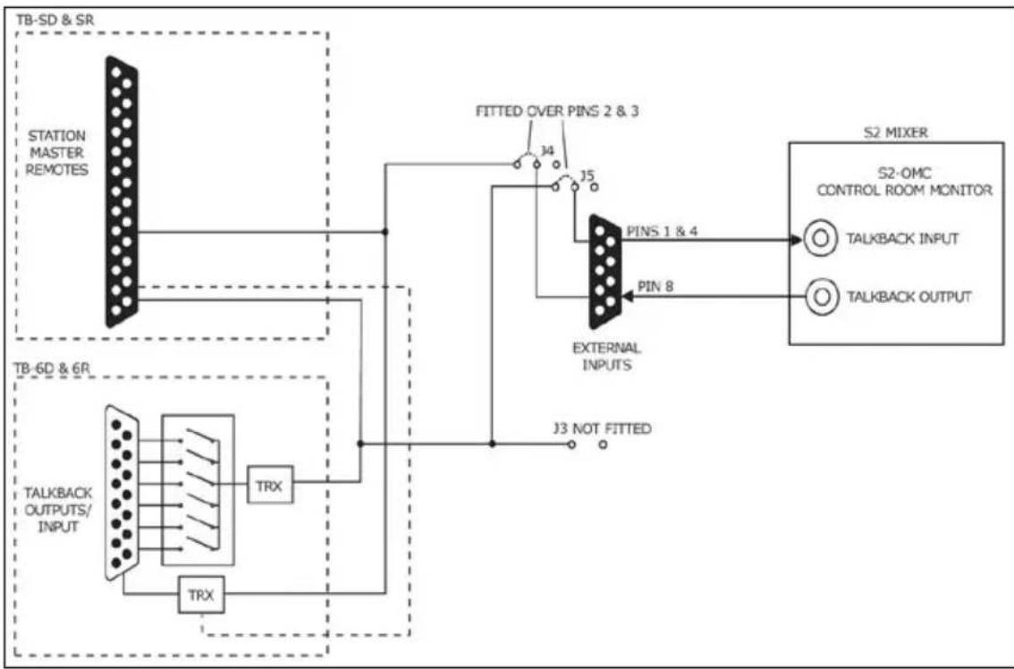
flowchart
graph TD
    A["TB-SD & SR"] --> B["STATION MASTER REMOTES"]
    B --> C["Fitted OVER PINS 2 & 3"]
    C --> D["External INPUTS"]
    D --> E["S2 MIXER"]
    E --> F["S2-OMC CONTROL ROOM MONITOR"]
    F --> G["TALKBACK INPUT"]
    F --> H["TALKBACK OUTPUT"]
    I["TB-6D & 6R"] --> J["TALKBACK OUTPUTS/INPUT"]
    J --> K["TRX"]
    K --> L["TRX"]
    L --> M["J3 NOT FITTED"]
    M --> N["PINS 1 & 4"]
    N --> O["PINS 8"]
    O --> P["External INPUTS"]
Fig: 7-6: Connecting The Talkback Intercom To The Sonifex S2 Mixer Output Module (S2-OMC).
8 Talkback Intercom Technical Specification
Audio & Power Specification
| Feature Value | |
| Talkback Input/Outputs | 15-way male ‘D’ type plug (TB-6D & TB-6R) for 6 balanced talkback outputs and 1 balance talkback input. |
| Talkback Input Gain Range | 9dB to -28dB adjusted by rear panel preset pot. |
| External Inputs & Mute | 9-way female ‘D’ type socket, for stereo balanced external input 1, stereo unbalanced external input 2 (or external talkback input/output), talkback control output and mute input. |
| External Input 2 | Dual phono socket, stereo unbalanced in parallel with the 9 way female ‘D’ type socket. |
| External Inputs Impedance | >30kΩ (unbalanced). |
| >40kΩ (balanced). | |
| External Talkback Input Impedance | >30kΩ (unbalanced). |
| External Talkback Output Impedance | <80Ω (unbalanced). |
| External Microphone Input | 3 pin female XLR socket. |
| Mic Input Impedance | 1.5kΩ balanced. |
| Microphone Input Gain Range | 74dB to 53dB adjusted by rear panel preset pot. |
| Headphone Output | 6.35mm jack, unbalanced stereo capable of driving 150mW into 32-600Ω headphones. |
| Headphone Output Gain Range | 9dB to<-60dB (off) adjusted by front panel pot. |
| Station Master Remotes 25-way female ‘D’ type socket (TB-SD & TB-SR). | |
| Loudspeaker power 1W. | |
| Mains Input Power IEC, 85V - 264V | AC, 47-63Hz, max 10W. |
| Fuse Holder 1A anti-surge fuse. | |

natural_image
Close-up of a white electronic device with a black circular button and a light blue abstract background (no visible text or symbols)
natural_image
Close-up of a white electronic device with a black screen and a light blue abstract graphic overlay (no readable text or symbols)Physical Specification
| Order Code | Description Height Width Depth Total | Nett Weight | Total Gross Weight | |||
| TB-6D TB-SD | Talkback intercom desk units | 6.1cm 22cm | 17.0cm 1.25kg 2.0kg | |||
| TB-6R TB-SR | Talkback intercom, 19" rack mounted | 8.9cm (2U) | 48.3cm (19" rack) | 18.5cm 2.60kg 4.0kg | ||


natural_image
Close-up of a white electronic device with a propeller and control panel (no visible text or symbols)NOTES


natural_image
Close-up of a white electronic device with a black circular button and a metallic blade, against a purple background (no visible text or symbols)NOTES


natural_image
Close-up of a white electronic device with a black circular button and a metallic blade, against a purple background (no visible text or symbols)NOTES
SONIFEX
www.sonifex.co.uk
t:+44 (0)1933 650 700
f:+44 (0)1933 650 726
sales@sonifex.co.uk

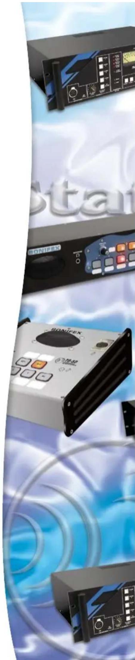
natural_image
Product display of SonoFEX audio equipment with control knobs and buttons (no visible text or symbols)- Station Master &
- Talkback Intercoms
- User Handbook
- Warranty & Safety Information i
- Station Master Introduction 1
- Talkback Introduction 26
- TB-6D & TB-6R 6 Way Talkback Intercom Configuration & Controls 34
- TB-SD & TB-SR Station Master Talkback Intercom Configuration & Controls 43
- Talkback Intercom Technical Specification 51
- Figures
- Warranty & Safety Information
- Warranty and Liability
- Important: the purchaser is advised to read this clause
- Returning the Warranty Card
- Unpacking the Station Master/Talkback Intercom
- Safety of Mains Operated Equipment
- Fuse Rating
- Power Cable and Connection
- Wire Colour Connection
- WEEE & RoHS Directives - Sonifex Statement
- Reporting Faults
- Serial No.
- Description of Error
- Additions that I Would Like to See
- Station Master Introduction
- Introduction
- Studio Switching
- Delay Control
- 1
- STATION MASTER INTRODUCTION
- Station Master
- Monitoring
- Audio Distribution
- Talkback
- Logging
- Power Failure
- Installation Notes
- Atmosphere
- Electromagnetic Radiation
- Connectors and Cabling
- XLR 3 Pin Connectors
- 1/4" 'A' Gauge Stereo Jack Plugs
- D-Type Connectors
- Operation
- Studio Feeds, Transmission Outputs and Logging Outputs
- Studio Feeds
- Transmission Outputs
- Logging Outputs
- Logging Off-Air instead of Pre-Transmission
- 2
- Enabling Talkback Over the Monitors
- Mixing or Ducking the Normal Monitor Output During Talkback
- Fixing the Monitor Output Level for the Phono Connectors
- Offer and Accept Switching
- Delay and Dump Control
- External Inputs
- Routing Of External Inputs
- Connection Details
- Audio Connections
- Studio Controls
- Controls In/Out 1 & 2
- Controls In/Out 3 & 4
- Balanced Logging Outputs
- Unbalanced Logging Outputs
- 3
- STATION MASTER CONNECTION DETAILS
- Other Connectors
- Mains Power
- Delay/Dump Control
- Monitor Output
- Monitor Insert
- Speaker Output
- Talkback Microphone Input
- Headphones
- 4
- STATION MASTER TECHNICAL SPECIFICATION
- Station Master Technical Specification
- Inputs/Outputs
- Frequency Response
- Noise (20Hz to 20kHz)
- Connections Summary
- Physical Specification
- Equipment Type
- 5
- TALKBACK INTERCOM INTRODUCTION
- Talkback Introduction
- TB-6D & TB-6R 6 Way Talkback Intercom Overview
- TALKBACK INTERCOM INTRODUCTION
- Example Application For TB-6D & TB-6R
- TB-SD & TB-SR Station Master Talkback Intercom Overview
- Example Application For TB-SD & TB-SR
- Talkback Intercom Benefits
- Station Master Features
- Station Master Talkback Operation and Connections
- 6
- TB-6D & TB-6R TALKBACK INTERCOM CONFIGURATION & CONTROLS
- TB-6D & TB-6R 6 Way Talkback Intercom Configuration & Controls
- Front Panel Control Details
- Power LED Indicator
- Level Control for Monitor Loudspeaker and Headphones
- External Select Switch 1
- External Select Switch 2
- Talkback Switches
- Built in Electret Microphone
- Monitor Loudspeaker
- External Microphone
- Rear Panel Control Details
- Headphone Output
- Mic Select
- Adjusting the Microphone Gain Level
- Adjusting the Talkback Gain Level
- External Input 2
- External Inputs & Mute Control
- TB-6D & TB-6R TALKBACK INTERCOM CONFIGURATION & CONTROLS
- Talkback Input/Outputs
- Fuse Holder
- Mains Input
- Internal Jumper Configuration
- External Input Muting/Mixing
- Local/External Talkback
- TB6 Interconnection Wiring Diagram Example Situations
- TB-SD & TB-SR Station Master Talkback Intercom Configuration & Controls
- Station Master Remotes
- 7
- TB-SD & TB-SR STATION MASTER TALKBACK INTERCOM CONFIGURATION & CONTROLS
- Talkback Intercom Technical Specification
- SONIFEX
Brand : Sonifex
Model : TB-6R
Category : Intercom