AVN-TB6D - Intercom Sonifex - Free user manual and instructions
Find the device manual for free AVN-TB6D Sonifex in PDF.


| Product Type | Intercom System |
| Brand | Sonifex |
| Model | AVN-TB6D |
| Dimensions (approx) | 200 x 150 x 50 mm |
| Weight | 1.0 kg |
| Power Supply | 12V DC, 1A (center positive) |
| Power Consumption | 5W max |
| Number of Stations | 6 (daisy-chainable) |
| Audio Mode | Full-duplex, hands-free |
| Connection Type | RJ45 (daisy-chain or star) |
| Mounting | Desktop (rubber feet included) |
| Controls | Volume, mute, station selection, call button |
| Indicators | LED for incoming call, mute, and power |
| Materials | ABS plastic front panel, metal base |
| Operating Temperature | 0°C to 40°C |
| Maintenance | Clean with soft dry cloth; avoid liquids and abrasives |
| Safety | Use only supplied power adapter; do not open or expose to moisture |
| Repairability | Contact Sonifex support; no user-serviceable parts |
| Warranty | 2 years limited |
Frequently Asked Questions - AVN-TB6D Sonifex
User questions about AVN-TB6D Sonifex
0 question about this device. Answer the ones you know or ask your own.
Ask a new question about this device
Download the instructions for your Intercom in PDF format for free! Find your manual AVN-TB6D - Sonifex and take your electronic device back in hand. On this page are published all the documents necessary for the use of your device. AVN-TB6D by Sonifex.
USER MANUAL AVN-TB6D Sonifex
6 Button Talkback Intercom (Freestanding)
AVN-TB6D
6 Button Talkback Intercom (Desktop)

Manufacturers of Audio Products for AV, Installed Sound, Broadcast Radio & Broadcast TV
SONIFEX
AVN-TB6 & AVN-TB6 Handbook
For the latest Sonifex handbook information please visit th Sonifex website at www.sonifex.co.uk
This handbook is for use with the following product:
AVN-TB6 & AVN-TB6D 6 Button Talkback Intercom
AW10890,
Stock Code: 30-371
Revision 1.02, August 2021
©Sonifex Ltd, 2021
All Rights Reserved
Sonifex Ltd, 61, Station Road, Irthlingborough,
Northants, NN9 5QE, England.
Tel: +44 (0)1933 650 700
Fax: +44 (0)1933 650 726
Email: sales@sonifex.co.uk
Website: https://www.sonifex.co.uk
Information in this document is subject to change without notice and does not represent a commitment on the part of the vendor. Sonifex Ltd shall not be liable for any loss or damage whatsoever arising from the use of information or any error contained in this manual.
No part of this manual may be reproduced or transmitted in any form or by any means, electronic or mechanical, including photocopying, recording, information storage and retrieval systems, for any purpose other than the purchaser's personal use, without the express written permission of Sonifex Ltd. Unless otherwise noted, all names of companies, products and persons contained herein are part of a completely fictitious adaptation and are designed solely to document the use of Sonifex product.
Made in the UK by SONIFEX
Contents
Product Warranty - 2 Year Extended i
Sonifex Warranty & Liability Terms & Conditions i
-
Definitions i
-
Warranty i
Unpacking Your Product ii
Repairs & Returns iii
CE Conformity iii
Safety & Installation of Mains Operated Equipment iii
Voltage Setting Checks iii
Fuse Rating iii
Power Cable & Connection iii
WEEE Directive iv
Atmosphere/Environment iv
- AVN-TB6 & AVN-TB6D 6 Button Talkback Intercoms
Introduction
- Installation
Network Connection
Microphone
GPIO
Power Supply
- Front Panel Controls, Connections & Indicators
Status Indicators
AoIP
Ethernet
Talk
AGC
Clock
AC PSU
DC PSU
Channel 1 to 6 Intercom Call Buttons
Listen Button
Page Button 7
Rotary Encoder Control 7
Reset Switch 7
Mon Button 7
User Button 7
LS Mute Button 7
Mic Mute Button 7
Microphone Input Connector 7
+48V Phantom Power Indicator 8
Headset Connector (AVN-TB6D only) 8
Headphone Output Connector 8
Power Switch 8
- Rear Panel Connections 9
1 Headset Connector (AVN-TB6 only) 10
1 GPI/O 10
3 Ethernet 1GB & AoIP 1GB Network Interfaces 10
3 AoIP SFP Interface 10
4 12V DC Input 10
4 Mains Fuse 11
4 Mains AC Input 11
5 5. Quick Start Guide 12
6 6. Intercom Calls 13
6 Making a Call 13
6 Receiving a Call 13
6 During a Call 13
6 Ending a Call 13
6 Group Calls 13
6 Call Signal 13
6 Auto Answer 14
7 Listen Button 14
Contents & Figures
Contents continued...
Call Functions 14
-
Intercom Calls with IFB 15
-
Non-Intercom Calls 16
-
Page 17
Making a Page 17
Receiving a Page 17
During a Page 17
Ending a Page 17
- Volume Control 18
Speaker & Headphone Volume 18
Call Channel Volume 18
Monitor Volume 18
Call Signal Volume 18
-
Network Address Announcement
-
Embedded Web Server
Information Tab 20
Device Information Web Page 20
Audio Assignments Web Page 22
GPIO Assignments Web Page 23
Configuration Tab 24
Network Web Page 25
AoIP Stream Settings Web Page 26
PTP Profiles Web Page 27
Channels - Basic Settings Web Page 29
Channels - Advanced Settings Web Page 30
Group Talk Web Page 31
Front Panel - Display Settings Web Page 32
Front Panel - Colour Settings Web Page 32
Front Panel - User Button Settings Web Page 33
Audio - Microphone Settings Web Page 34
Audio - Monitor & Speaker Settings Web Page 35
Page Settings Web Page 36
GPIO Settings Web Page 37
Virtual GPIO Settings Web Page 38
Miscellaneous Settings Web Page 39
System Tab 39
- Ember+ Interface 42
Connecting to the Ember+ Interface 42
GPIO 42
Type Parameter 43
Input Function Parameter 43
Input Action Parameter 43
Output Trigger Parameter 43
Status Parameter 43
Set Output Function 43
Relay 43
Trigger Parameter 43
Status Parameter 43
Active Function 43
Virtual GPIO Control 44
Type Parameter 44
Input Function Parameter 44
Input Driver Name Parameter 44
Output Trigger Parameter 44
Status Parameter 44
Set Output Function 44
Parameter Value Specification 45
Identity 45
Network 45
AoIP 45
PTP 45
Figures
Fig 1-1: The AVN-TB6 Front Panel 1
Fig 1-2: The AVN-TB6D Front Panel 1
Fig 2-1: Preferred Network Topology 3
Fig 3-1: AVN-TB6 and AVN-TB6D Front Panels 5
Fig 4-1: AVN-TB6 and AVN-TB6D Rear Panels 9
Table 6-1: Call Functions 14
Fig 12-1: Upper Section of Device Information Web Page 20
Fig 12-2: Lower Section of Device Information Web Page 21
Fig 12-3: Audio Assignments Web Page 22
Fig 12-4: Upper Section of GPIO Assignments Web Page 23
Fig 12-5: Lower Section of GPIO Assignments Web Page 24
Fig 12-6: Network Web Page 25
Fig 12-7: AoIP Stream Settings Web Page 26
Fig 12-8: Upper Section of PTP Profiles Web Page 27
Fig 12-9: Lower Section of PTP Profiles Web Page 27
Fig 12-10: Channels - Basic Settings Web Page 29
Fig 12-11: Channels - Advanced Settings Web Page 30
Fig 12-12: Group Talk Web Page 31
Fig 12-13: Front Panel - Display Settings Web Page 32
Fig 12-14: Front Panel - Colour Settings Web Page 32
Fig 12-15: Front Panel - User Button Settings Web Page 33
Fig 12-16: Audio - Microphone Settings Web Page 34
Fig 12-17: Audio - Monitor & Speaker Settings Web Page 35
Fig 12-18: Page Settings Web Page 36
Fig 12-19: GPIO Settings Web Page 37
Fig 12-20: Virtual GPIO Settings Web Page 38
Fig 12-21: Miscellaneous Settings Web Page 39
Fig 12-22: Update Firmware Section of System Web Page 39
Fig 12-23: Save Configuration Section of System Web Page 40
Fig 12-24: Load Configuration Section of System Web Page 40
Fig 12-25: Save System Log Section of System Web Page 41
Fig 13-1: Ember+ Root Structure 42
Fig 13-2: Ember+ GPIO Branch Structure 42
Fig 13-3: Ember+ Relay Node Structure 43
Fig 13-4: Ember+ Virtual GPIO Branch Structure 44
Table 15-1:DSCP Names & Their Corresponding IP Precedence 52
Warranty Registration
SONIFEX
Register Online for an Extended 2 Year Warranty
As standard, Sonifex products are supplied with a 1 year back to base warranty.
If you register the product online, you can increase your product warranty to 2 years and we can also keep you informed of any product design improvements or modifications.
Product: ____ Serial No: ____
To register your product, please go online to www.sonifex.co.uk/register
SONIFEX
Sonifex Limited • 61 Station Road • Irthlingborough • Northamptonshire • NN9 5QE • United Kingdom
Tel: +44 (0)1933 650 700 • Fax: +44 (0)1933 650 726 • Email: technical.support@sonifex.co.uk • Internet: www.sonifex.co.uk
Warranty
Product Warranty - 2 Year Extended
As standard, Sonifex products are supplied with a 1 year back warranty. In order to register the date of purchase and so th you informed of any product design improvements or modification important to complete the warranty registration online. Additional
register the product on the Sonifex website, you can increase warranty to 2 years. Go to the Sonifex website at: www.sonife register to apply for your 2 year warranty.
This is the entire Contract between the parties relating to the subject matter hereof and may not be changed or terminated except in writ to base accordance with the provisions of this Contract. A reference to the acknowledgement, authority or agreement of the Company means in writing and only by a director of the Company.
, if you
our product 2. Warranty
.co.uk/a. The Company agrees to repair or (at its discretion) replace Goods which are found to be defective (fair wear and tear excepted) which are returned to the Company within the Warranty Term provided that each of the following are satisfied:
i. notification of any defect is given to the Company immediate upon its becoming apparent to the Purchaser;
ii. the Goods have only been operated under normal operating conditions and have only been subject to normal use (and Company particular the Goods must have been correctly connected ar tems must not have been subject to high voltage or to ionising software radiation and must not have been used contrary to the Company's technical recommendations);
Sonifex Warranty & Liability Terms & Conditions
1. Definitions
'the Company' means Sonifex Ltd and where relevant includes companies
within the same group of companies as Sonifex Limited.
'the Goods' means the goods or any part thereof supplied by the and where relevant includes: work carried out by the Company on supplied by the Purchaser; services supplied by the Company; and supplied by the Company.
agreed. The Goods are returned to the Company's premises at the Purchaser's expense;
'the Purchaser' means the person or organisation who buys or has to buy the Goods.
'the Price' means the Price of the Goods and any other charges the Company in the supply of the Goods.
curred by IV. any Goods or parts of Goods replaced shall become the property of the Company;
'the Warranty Term' is the length of the product warranty which
12 months from the date of despatch; except when the product registered at the Sonifex website when the Warranty Term is 24 is v. no work whatsoever (other than normal and proper has been maintenance) has been carried out to the Goods or any p months the Goods without the Company's prior written consent; from the date of despatch.
'the Contract' means the quotation, these Conditions of Sale and any document incorporated in a contract between the Company and the Purchaser.
vi. the defect has not arisen from a design made, furnished or
specified by the Purchaser;
Warranty
vii. the Goods have been assembled or incorporated into other goods only in accordance with any instructions issued by Company;
viii. the defect has not arisen from a design modified by the Purchaser;
ix. the defect has not arisen from an item manufactured by a person other than the Company. In respect of any item manufactured by a person other than the Company, the Purchaser shall only be entitled to the benefit of any way guarantee provided by such manufacturer to the Company.
b. In respect of computer software supplied by the Company the Company does not warrant that the use of the software will uninterrupted or error free.
c. The Company accepts liability:
(i) for death or personal injury to the extent that it results in negligence of the Company, its employees (whilst in the course of their employment) or its agents (in the course of the
(ii) for any breach by the Company of any statutory undertak- to title, quiet possession and freedom from encumbrance.
d. Subject to conditions (a) and (c) from the time of despatch of Goods from the Company's premises the Purchaser shall be responsible for any defect in the Goods or loss, damage, nuisance interference whatsoever consequential economic or otherwise or wastage of material resulting from or caused by or to the Goods particular the Company shall not be liable for any loss of prior other economic losses. The Company accordingly excludes all liability for the same.
e. At the request and expense of the Purchaser the Company will be a separate Goods to ascertain performance levels and provide a report of also
results of that test. The report will be accurate at the time of the best of the belief and knowledge of the Company, and the Company accepts no liability in respect of its accuracy beyond that set out in Condition (a).
f. Subject to Condition (e) no representation, condition, warranty or other term, express or implied (by statute or otherwise) is given by the Company that the Goods are of any particular quality or standard or will enable the Purchaser to attain any particular performance or result, or will be suitable for any particular purpose or use under warranty or specific conditions or will provide any particular capacity, and any. notwithstanding that the requirement for such performance, result or the capacity or that such particular purpose or conditions may have been well be known (or ought to have been known) to the Company, its employees or agents.
g. (i) To the extent that the Company is held legally liable to the Purchaser for any single breach of contract, tort, representation of its from the course or other act or default, the Company's liability for the same shall not exceed the price of the Goods.
(ii) The restriction of liability in Condition (g)(i) shall not apply to g as any liability accepted by the Seller in Condition (c).
h. Where the Goods are sold under a consumer transaction (as defined of the by the Consumer Transactions (Restrictions on Statements) Order 1976) the statutory rights of the Purchaser are not affected by these nuisance or Conditions of Sale.
Unpacking Your Product profits or
Each product is shipped in protective packaging and should be inspected for damage before use. If there is any transit damage take pictures of the product packaging and notify the carrier immediately with all the relevant details of the shipment. Packing materials should be kept for inspection and also for if the product needs to be returned.
The product is shipped with the following equipment so please ensure that you have all of the items below. If anything is contact the supplier of your equipment immediately.
Item Quantity
Product unit 1
IEC mains lead fitted with moulded mains plug 1
Handbook 1
check to safety & Installation of Mains issing, please Operated Equipment
There are no user serviceable parts inside the equipment. If you should ever need to look inside the unit, always disconnect the mains supp before removing the equipment covers. The cover is connected to ea means of the fixing screws. It is essential to maintain this earth/gro connection to ensure a safe operating environment and provide electromagnetic shielding.
If you require a different power lead, please let us know when product.
Repairs & Returns
Please contact Sonifex or your supplier if you have any problems. Please note that all products are either switchable between 115V and Sonifex product. Email technical.support@sonifex.co.uk for the repair, or have a universal power supply. upgrade/returns procedure, or for support & questions regarding the product operation. Fuse Rating
CE Conformity
The products in this manual comply with the essential requirements of the rating and type of fuse is used. Incorrectly rated fuses could present relevant European health, safety and environmental protection legislation possible fire hazard, under equipment fault conditions. The active fuse fitted on the outside rear panel of the unit. The technical justification file for this product is available at Sonifixed Ltd.
The declaration of conformity can be found at: http://www.sonifex.co.uk/declarations
nVollager the Setting Checks
Ensure that the machine operating voltage is correct for your mains supply by checking the box in which your product was supplied. The is shown on the box label. The available voltage settings are 115V,
Fuse Rating
The product is supplied with a single fuse in the live conducting power input. For reasons of safety it is important that the components of the rating and type of fuse is used. Incorrectly rated fuses could present possible fire hazard, under equipment fault conditions. The active fuse fitted on the outside rear panel of the unit.
Power Cable & Connection
An IEC power connector is supplied with the product which has a plug attached.
The mains plug or IEC power connector is used as the disconnect of. The mains plug and IEC power connector shall remain readily operable disconnect the apparatus in case of a fault or emergency.
The mains lead is automatically configured for the country that the is being sent to, from one of:
Safety & Installation
Territory Voltage IEC Lead Type Image
| UK & Middle East | 230V | UK 3 pin to IEC lead | |||
| Europe 230V | European IEC lead | Schuko round 2 pin | |||
| USA, Canada and South America | 115V | 3 flat pin to IEC lead | |||
| Australia & New Zealand | 230V | Australasian 3 flat pin to IEC lead | |||
Connect the equipment in accordance with the connection details before applying power to the unit, check that the machine has operating voltage for your mains power supply.
This apparatus is of a class I construction. It must be connected socket outlet with a protective earthing connection.
Important note: If there is an earth/ground terminal on the rear the product then it must be connected to Earth.
WEEE Directive

The Waste Electrical and Electronic Equipment (WEEE) Directive was agreed on 13 February 2003, along with the related Directive 2002/95/EC on Restrictions of the use of certain Hazardous Substances in electrical and electronic
equipment (RoHS). The Waste Electrical and Electronic Equipment Directive (WEEE) aims to minimise the impacts of electrical and electronic equipment on the environment during their life times and when they become waste. All products manufactured by Sonifex Ltd have the WEEE directive label and placed on the case. Sonifex Ltd will be happy to give you information about the correct local organisations that can reprocess the product when it reaches its "end of use", or alternatively all products that have reached "end of use" can be
Atmosphere/Environment panel of
This apparatus should be installed in an area that is not subject to excess temperature variation ( <0^ , >50^ ), moisture, dust or vibration.
This apparatus shall not be exposed to dripping or splashing, and no object filled with water, such as vases shall be placed on the apparatus.
1. AVN-TB6 & AVN-TB6D 6 Button Talkback Intercoms
Introduction
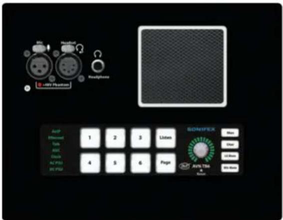
The AVN-TB6 and AVN-TB6D are 6 channel talkback intercom control units from the Sonifex range of IP based AVN (Audio/Video/Network) products. The AVN-TB6 is a freestanding version, which can be converted into a 1U rackmount using the AVN-TB6RK rack-kit. The AVN-TB6D is a desktop version that can be fitted flush into a work surface if required. Both models offer similar functionality.

Fig 1-1: The AVN-TB6 Front Panel
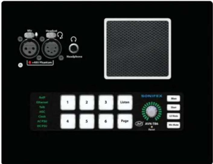
Fig 1-2: The AVN-TB6D Front Panel
1 Introduction
These units provide broadcast quality audio communication between studios, offices and different areas in a facility or building complex, using RAVENNA/AES67 as the transport mechanism, allowing simple CAT 5 cabling and expansion.
RAVENNA (of which AES67 is a subset) allows for the distribution of audio across a network. The AVN range use RAVENNA as the communication method providing compatibility with other AES67 systems.
Each of the 6 channels on the AVN-TB6 and AVN-TB6D can be configured to provide communications with other remote networked intercom units or AoIP streams, and an independently configurable page function can contact selected units with priority over standard intercom calls if required.
There is a monitor channel that can route the audio from an AoIP source to the headphones and speaker. This could be used to take an IFB feed or an off-air transmission signal or simply to listen to any audio source.
A user configurable GPIO system, with 10 physical ports and 10 virtual ports, can be used to control operational functions on local or networked units, or drive outputs as selected states change, and a voltage free relay contact can be used to operate external equipment.
A built-in web server provides complete configuration control of the units and also allows for firmware updates and configuration backup. An Ember+ interface also gives access to the configuration options as well as providing remote control and monitoring of the GPIO and virtual GPIO ports.
2. Installation
Network Connection
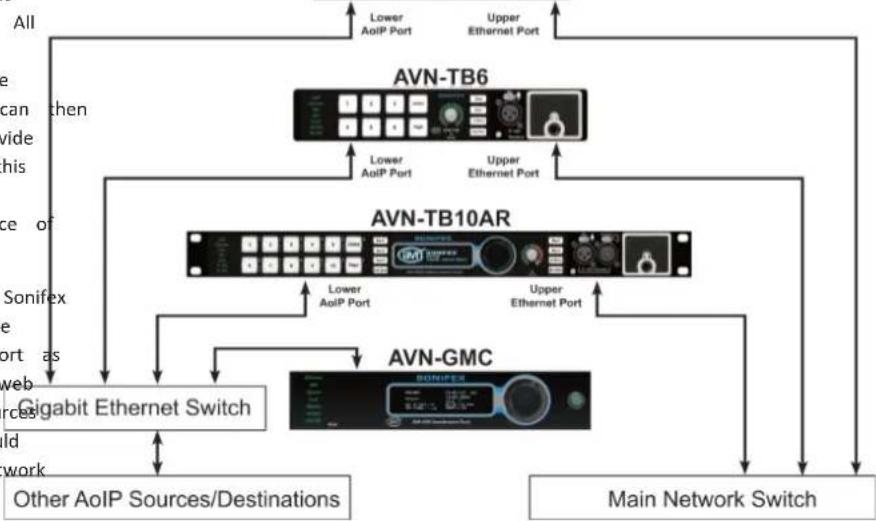
The AVN-TB6 and AVN-TB6D have 2 separate gigabit network ports:
Upper Port: Configuration and control interface Lower Port: Audio over IP (AoIP) interface
In an ideal installation, the lower port should be connected to a dedicated network switch that handles audio and audio related traffic only. All other intercom units, AoIP sources and destinations, and grandmaster clocks should be connected to this network. The upper port can be connected to a separate network to provide access to the embedded web server. With this setup, potentially heavy network traffic on a company LAN does not affect the performance of the AoIP network.
The AVN-TB6 and AVN-TB6D and any other Sonifex talkback intercoms can be used with a single network connection using the lower (AoIP) port as this also provides access to the embedded web server. The talkback intercom units, AoIP sources and destinations, and grandmaster clocks should still ideally be connected to a dedicated network switch.
flowchart
graph TD
    A["Main Network Switch"] --> B["AVN-TB6"]
    A --> C["AVN-TB10AR"]
    A --> D["AVN-GMC"]
    B --> E["Gigabit Ethernet Switch"]
    C --> F["Other AoIP Sources/Destinations"]
    C --> G["Lower AoIP Port"]
    C --> H["Upper Ethernet Port"]
    C --> I["Lower AoIP Port"]
    C --> J["Upper Ethernet Port"]
    C --> K["Lower AoIP Port"]
    C --> L["Lower AoIP Port"]
    C --> M["Lower AoIP Port"]
    C --> N["Lower AoIP Port"]
    C --> O["Lower AoIP Port"]
    C --> P["Lower AoIP Port"]
    C --> Q["Lower AoIP Port"]
    C --> R["Lower AoIP Port"]
    C --> S["Lower AoIP Port"]
    C --> T["Lower AoIP Port"]
    C --> U["Lower AoIP Port"]
    C --> V["Lower AoIP Port"]
    C --> W["Lower AoIP Port"]
    C --> X["Lower AoIP Port"]
    C --> Y["Lower AoIP Port"]
    C --> Z["Lower AoIP Port"]
    C --> AA["Lower AoIP Port"]
    C --> AB["Lower AoIP Port"]
    C --> AC["Lower AoIP Port"]
    C --> AD["Lower AoIP Port"]
    C --> AE["Lower AoIP Port"]
    C --> AF["Lower AoIP Port"]
    C --> AG["Lower AoIP Port"]
    C --> AH["Lower AoIP Port"]
    C --> AI["Lower AoIP Port"]
    C --> AJ["Lower AoIP Port"]
    C --> AK["Lower AoIP Port"]
    C --> AL["Lower AoIP Port"]
    C --> AM["Lower AoIP Port"]
    C --> AN["Lower AoIP Port"]
    C --> AO["Lower AoIP Port"]
    C --> AP["Lower AoIP Port"]
    C --> AQ["Lower AoIP Port"]
    C --> AR["Lower AoIP Port"]
    C --> AS["Lower AoIP Port"]
    C --> AT["Lower AoIP Port"]
    C --> AU["Lower AoIP Port"]
    C --> AV["Lower AoIP Port"]
    C --> AW["Lower AoIP Port"]
    C --> AX["Lower AoIP Port"]
    C --> AY["Lower AoIP Port"]
    C --> AZ["Lower AoIP Port"]
    C --> BA["Lower AoIP Port"]
    C --> BB["Lower AoIP Port"]
    C --> BC["Lower AoIP Port"]
    C --> BD["Lower AoIP Port"]
    C --> BE["Lower AoIP Port"]
    C --> BF["Lower AoIP Port"]
    C --> BG["Lower AoIP Port"]
    C --> BH["Lower AoIP Port"]
    C --> BI["Lower AoIP Port"]
    C --> BJ["Lower AoIP Port"]
    C --> BK["Lower AoIP Port"]
    C --> BL["Lower AoIP Port"]
    C --> BM["Lower AoIP Port"]
    C --> BN["Lower AoIP Port"]
    C --> BO["Lower AoIP Port"]
    C --> BP["Lower AoIP Port"]
    C --> BQ["Lower AoIP Port"]
Fig 2-1: Preferred Network Topology
2 Installation
Microphone
These units have connections for a microphone via a 3 pin XLR on the front panel, or a headset via a 5 pin XLR. The headset connector is located on the rear panel of the AVN-TB6. On the AVN-TB6D, the headset connector is located on the front panel. Only one microphone or headset should be connected. If phantom power is required, this can be enabled via the webserver. See Audio - Microphone Settings web page on page 34 for details.
GPIO
The GPIO connector provides 10 ports, individually configurable as either inputs or outputs, via a 15 way 'D' type connector. Connection details are shown on Outputs are open collector driven, and inputs are active low. See GPIO Settings web page on page 37 for details.
Power Supply
The units can be powered from the mains via the supplied IEC lead, or by using the optional external 12V DC power supply, part number AVN-DC150. Please contact Sonifex Ltd sales for more details. Both power supplies can be connected and powered at the same time to provide redundancy if required.
3. Front Panel Controls, Connections & Indicators
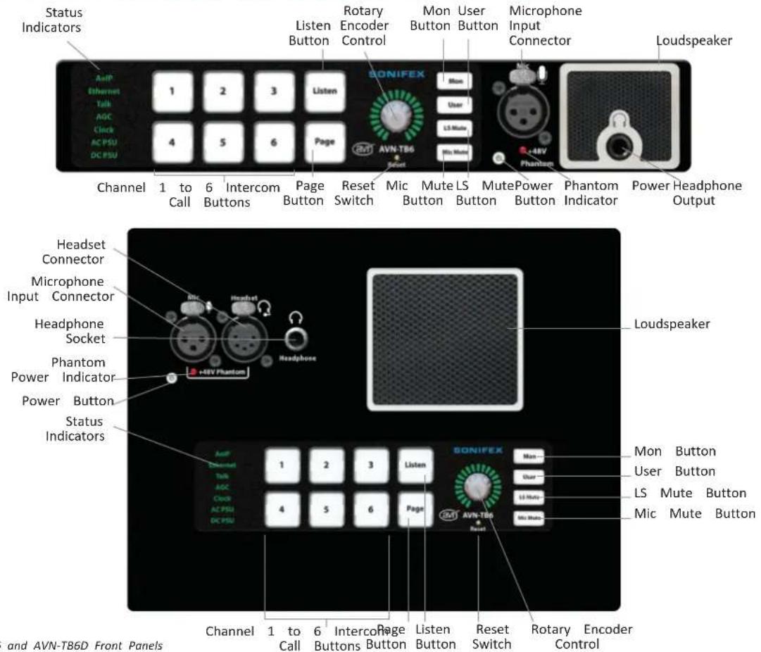
Fig 3-1: AVN-TB6 and AVN-TB6D Front Panels
3 Front Panel Controls, Connections & Indicators
Status Indicators
The RGB status indicators are located on the left side of the
AoIP
Indicates the status of AoIP services on the network as follows:
Green All transmit AoIP streams are available and at least one external AoIP service is available.
Amber Either the transmit AoIP stream has not started or there are no external AoIP services available.
Off The transmit AoIP stream has not started and there are no external AoIP services available. The indicator also be off if there is no link on the AoIP (lower network connector).
The AoIP network interface is configured via the embedded web the Network web page on page 25.
Ethernet
Indicates the link status of the Ethernet network port (upper connector) as follows:
Green The link is up.
Off The link is down.
The Ethernet network interface is configured via the embedded See the Network web page on page 25.
Talk
Illuminates green if an intercom call or page is active.
AGC
Indicates the status of the automatic gain control as follows:
Green The AGC is enabled.
front panel audio source level for one of the outputs is too high and is being limited. The monitored outputs are the headphone/headset output and the speaker output.
Clock
Indicates the status of PTP clock as follows:
Green The unit is a PTP slave with a clock offset of less or equal to ±1 s or the unit is the PTP master.
Amber The unit is a PTP slave with a clock offset of between ±1 s and ±10 s .
work port Flash Amber The unit is in a listening state and is not yet acting as the master or a slave.
Red The See unit is a PTP slave with a clock offset of greater than ±10μs.
Flash Red The unit is a PTP slave and no master is available.
AC PSU
Indicates the status of the internal AC-DC power supply as follows:
Green AC-DC generated voltage is within normal operating range of +11V to +13V. This is the normal condition.
web server AmbeP AC-DC generated voltage is less than +11V or greater than +13V. This indicates a warn condition.
Red AC-DC generated voltage is less than +10V or greater than +14V. This indicates a fault condition.
DC PSU
Indicates the status of the DC power input as follows:
Green DC voltage is within normal operating range of +11V to +13V. This is the normal condition.
Amber DC voltage is less than +11V or greater than +13V. This indicates a warn condition.
Red Not connected or DC voltage is less than +10V or greater than +14V. This indicates a fault condition power source is connected.
Channel 1 to 6 Intercom Call Buttons
These buttons initiate an intercom call to a pre-configured target unit or AoIP stream. The channels are configured via the embedserver. See the Channels - Advanced Settings web page on page
Listen Button
This button is used when making an intercom call to change type. See Listen Button on page 14 for more details.
Page Button
The page button initiates a talk only call to a pre-configured intercom units. The button flashes red when active. The target selected via the embedded web server. See the Page Settings page 36.
Rotary Encoder Control
The rotary encoder control is used to set the volume levels of headphones, speaker and the input levels for the various audio Volume Control on page 18 for details.
Reset Switch
The recessed reset switch, located below the rotary encoder co a full hardware reset.
Mon Button
This button activates the monitor channel. The monitor can be set to provide audio from any AoIP source. To configure the monitor, see Audio - Monitor & Speaker Settings web page on page 35 for detail
User Button if a DC
This button is configurable and can be used to control various functions the unit. To configure this button, see the Front Panel - User Button page in on page 33.
: intercom LS Mute Button
This button mutes the audio feed to the speaker. The button illuminates the 30. when the mute function is active. The operational mode of the butt user configurable, see the Audio - Monitor & Speaker Settings web | page 35 for details. The default call
Mic Mute Button
This button can be used to temporarily mute the microphone/headset input. The button illuminates red when active. The operational mode of button target user configurable, see the Audio - Microphone Settings web Intercoms are for details. web page on
Microphone Input Connector
This 3 pin XLR socket is the connection for the microphone. The connections are as follows:
Pin 1: Ground Inputs. See
Pin 2: Microphone Phase
Pin 3: Microphone Non-Phase
Phantom power can be supplied if required. To change the mic setti
the, Audiees- Microphone Settings web page on page 34 for details.
3 Front Panel Controls, Connections & Indicators
+48V Phantom Power Indicator
This indicator illuminates red when the phantom power supply is enabled. To change the phantom power setting, see the Audio - Microphone Settings web page on page 34 for details.
Headset Connector (AVN-TB6D only)
This 5 pin XLR socket is the connection for the headset. The connections are as follows:
Pin 1: Microphone Non-Phase
Pin 2: Microphone Phase
Pin 3: Ground
Pin 4: Headphone Left
Pin 5: Headphone Right
Phantom power can be supplied if required. To change the headset settings, see the Audio - Microphone Settings web page on page 34 for details.
Headphone Output Connector
The headphone connection is via a 6.35mm (¼ inch) jack socket. The connections are as follows:
Tip: Headphone Left
Ring: Headphone Right
Sleeve: Ground
When headphones are connected, the speaker mute is automatically activated.
Power Switch
The power switch turns the unit on and off. When the unit is on, the indicator is green. When the unit is off, the indicator is red. The power switch can be disabled if required, see the Miscellaneous Settings web page on page 39 for details.
4. Rear Panel Connections
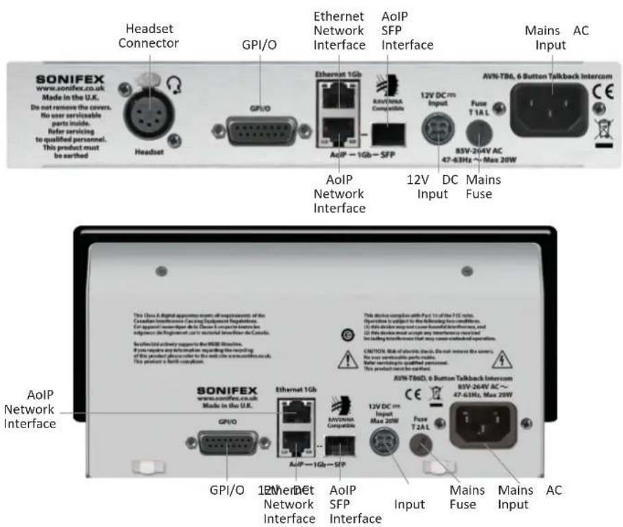
Fig 4-1: AVN-TB6 and AVN-TB6D Rear Panels
4 Rear Panel Connections
Headset Connector (AVN-TB6 only)
This 5 pin XLR socket is the connection for the headset. The as follows:
Pin 1: Microphone Non-Phase
Pin 2: Microphone Phase
Pin 3: Ground
Pin 4: Headphone Left
Pin 5: Headphone Right
Phantom power can be supplied if required. To change the headset settings,
see the Audio - Microphone Settings web page on page 34 for
GPI/O
This 15 pin 'D' type socket provides 10 configurable general purpiterfair inputs used, the AoIP network port cannot be used at the same time or outputs and a voltage free switching relay contact. The connections are
as follows:
Pin 1 GPIO Port 1
Pin 2 GPIO Port 2
Pin 3 GPIO Port 3
Pin 4 GPIO Port 4
Pin 5 GPIO Port 5
Pin 6 Relay - Normally Open Contact
Pin 7 Relay - Normally Closed Contact
Pin 8 Relay - Common
Pin 9 GPIO Port 6
Pin 10 GPIO Port 7
Pin 11 GPIO Port 8
Pin 12 GPIO Port 9
Pin 13 GPIO Port 10
Pin 14 Fused (200mA) +12VDC Supply
Pin 15 Ground
GPIO ports configured as an output are open collector type. GPIO inputs are active low. See the GPIO Settings web page on page 37 for details on how connections are configure the GPIO and relay settings.
Ethernet 1GB & AoIP 1GB Network Interfaces
These RJ45 connectors are the gigabit network ports. The upper connector is the configuration and control port and the lower connector is the audio over IP (AoIP) port.
AOP SFP Interface
This SFP (small form-factor pluggable) connector allows an alternative interface type to be used for the AoIP port, for example fibre. If a SFP
rioterfairputs used, the AoIP network port cannot be used at the same time ections are
12V DC Input
This 4 pin connector allows an external +12V power supply to be used to power the unit. When looking at the rear of the unit, the pin locations a connections are as follows:
Location Connection
Pin 1 Upper Left +12V DC
Pin 2 Upper Right +12V DC
Pin 3 Lower Left 0V
Pin 4 Lower Right OV
Both the 12V DC input and the mains AC input can be connected at the same time.
Mains Fuse
This 20mm x 5mm anti-surge mains fuse is rated at 2A.
Mains AC Input
This universally filtered IEC is the mains AC input power supply to the unit.
5 Quick Start Guide
5. Quick Start Guide
This section outlines the steps required to get the AVN-TB6/AVN-T connected to a network and in a state where it can make and intercom calls.
be determined by using the network address announcement function.
See Network Address Announcement on page 19 for details.
If a dedicated grandmaster clock, such as the AVN-GMC from Sonifex, is receiving to be used as the master PTP clock for the network audio system. The PTP profile on the AVN-TB6/AVN-TB6D will need to be set to the
- Connect the upper Ethernet port to a suitable network to access sufficient setting on the grandmaster device. On the web page, select PTP web server to configure the initial settings. By default this port Profiles from the configuration tab. Select the required profile from the configured to use the static IP address 192.168.0.100. drop down list box and ensure that the domain number for the
- Apply power to the unit via the IEC mains connection or via an elected profile matches the grandmaster setting. Press the submit 12V DC power supply. button to save the new settings. If no dedicated grandmaster device is
- Once the unit is powered, open a web browser and connect to the that connected intercom units will automatically establish a by entering the IP address 192.168.0.100 into the browser address master. clock hierarchy. In this case, the default profile can be used. Once connected, the device information web page will be shown. Connect the lower AoIP port to the audio network.
- On the web page, select Network from the configuration tab 9 and On the web page, select Microphone Settings from the Audio sub tab. configure the Ethernet and AoIP ports to the required settings. Select IP the required microphone type, with or without phantom power. addresses assigned to the 2 ports must be on different subnets. No for change the microphone or headset gain so that metering LEDs example, with the subnet mask on both ports set to 255.255.255 around the front panel rotary control peak in the amber section for the IP address on the Ethernet port is set to 192.168.0.100, then AoIP speech. Press the submit button to save the new settings. port must be set to 192.168.x.y where x is not 0 and y is 0. The final step is to assign remote intercoms or AoIP streams to the chosen subnet. required channels. On the web page, select Basic Settings from the
- Although not essential at this point, it is a good idea to assignChannels sub tab. Select the required remote intercom or AoIP stream recognisable intercom name so that other users can easily identify and the Available AoIP Sources list box at the top of the page. This use services from this unit. shows a dynamic list of currently available intercom devices including
- To simplify the configuration process, make sure the Auto Multicathose with IFB, and AoIP streams on the network. To configure a option is enabled. This removes the need to set the transmit AdHannel for the selected AoIP source, press the corresponding assign multicast IP address as it will be configured automatically based buttothe For sources that are not currently available, the source name AoIP port IP address. Once the settings on the network page have been manually entered in the edit box for each channel. For intercon configured, press the submit button to save them to the connect assignments, a channel on the selected device will need to be assigned unit. When the network settings have been changed, the unit with this unit in order to make intercom calls. Press the submit button automatically restart. If the settings of the network port the browser the new settings. connected to have changed, a new connection for the brows: The winit should now have the minimum settings configured to allow need to be established using the new IP address. If dynamicaddress calls between devices and AoIP streams. mode has been selected, the active IP address for the network port can
6. Intercom Calls
Each channel button on the front panel can be assigned to a unit in order to make and receive voice calls. See the Channe Settings web page on page 30 for full details of the available
During a Call
Where an intercom call is connected, the channel button is illuminated, the advanced assigned to the call type. The intercom unit that initiates always dictates the call type. If the monitor channel is active when intercom call is connected, the audio routed to the headphones or from the monitor source is automatically muted or dimmed according
Making a Call
To make a call request, press the channel button assigned to remote unit. If the called unit has the auto answer option er will be connected immediately. The button status for an active
the monitor settings. the required
described later in this section. If the called unit's auto answer disabled, the selected channel button will slowly flash using the assigned to the default function for that channel. For example, function is talk and listen, and the colour assigned to the talk
Ending a Call call is
Optionative call can be terminated by either party. To end a call, pr illuminated channel button. The call is ended immediately and the bu illumination defaults turned off. If the monitor channel is active, it will re find normal state when all calls have ended.
buttons is amber, the button will flash amber. If a call request is made to an intercom that doesn't have a valid channel assignment for the calling unit,
the call will be cancelled. To correct this error, assign the int the unit attempting to make the call to a channel on the ta
from name from intercom calls can be made simultaneously to multiple remote units (get the group talk function. The group talk set can include any combina channels, see the Group Talk web page on page 31 for details. Group calls
are selected by assigning the group talk function to the user button,
Receiving a Call
When an intercom call request is received from a remote unit, handled by the local channel assigned to the calling intercom of the call is handled is dependent on the auto answer option s
Front callanovill- based Button web page on page 33 for details. The linkethetowale group talk set, can then be used to make or end a setting for the
local channel. If the auto answer option is enabled, the call is
connected Signal
immediately. If the auto answer option is disabled, the channel assigned to the caller will rapidly flash using the colour assigne requested call type. For example, if the calling unit has requests call, the call will be treated locally as listen only. If the local
The call signal provides an audible indication that an incoming call is to be answered. It can be heard in the headphones and through the talk only speaker. If the call signal is not required, it can be turned off. See channels assignment Advanced Settings web page on for details.
for listen buttons is green, the channel button will flash green. If the call signal is enabled, a repeated audible signal will be heard in the headphones or speaker. The call is answered by pressing the flashing channel button and the audio from each unit will be routed depending on the callers selected call type.
6 Intercom Calls
Auto Answer
Call Functions
The auto answer option is individually configurable for each channel. Following table shows the corresponding call functions between the incoming call request on a channel that has this option enabled calling code receiving unit. The default channel button colours for the call immediately. To change the auto answer settings, see the Channetype is also shown.
Advanced Settings web page on page 30 for details.
Listen Button
Each channel has a default function option that selects the type is initiated when the corresponding channel button is pressed. See
Channels - Advanced Settings web page on page 30 for details. panel listen button can be used to change the default call func only, talk and listen or talk forced listen. To override the default a channel, press the listen button. The first press will select list
the button will illuminate using the colour assigned listen buttons. Table Second Functions
press will select talk and listen, and the button will illuminate a colour assigned to talk and listen buttons. A third press will sel forced listen, and the button will flash alternately using the color assigned to both talk and listen buttons. A fourth press will can function and the button illumination will turn off. Once the listen indicates the required call function, press a channel button to ca assigned unit. If a channel button is not pressed within 3 second listen button press, the listen function is cancelled.
| Calling Unit Receiving Unit | |||
| Call Type Default | ChannelButton Colour | Call Type Default | ChannelButton Colour |
| Talk Only Redof call that | Listen Only Green | ||
| Listen Only Green | Talk Only | Red | |
| Talk & Listen | Amber | Talk & Listen | Amber |
| Talk Forced ListtionTalkoitiveT Talk ActiveYoren only and | Green with RedFlRed with Green | Talk Forced ListlenFlTalk OnlyTalk & Listen | RedAmber |
using the The Talk Forced Listen call works differently to the standard talk/listen select talk functions. When this type of call is initiated, the call starts as a listen on ours call. The callers channel button is illuminated using the colour assigned to cancel the listen listen buttons, with a brief flash using the colour assigned to talk buttons. en button The channel button on the receiving unit is illuminated to indicate a talk all the call. The calling unit can then repeatedly press the channel button to enable nds of the last and disable talk. When talk is enabled, the channel button illuminates using the colour assigned to talk buttons, with a brief flash using the colour assigned to listen buttons. The channel button on the receiving unit is illuminated to indicate a talk & listen call when the callers talk is enabled The receiving unit can end the call by pressing the channel button as per other call functions. The calling unit ends the call by briefly holding the channel button until the illumination has turned off.
7. Intercom Calls with IFB
Other models in the AVN Talkback range, such as the AVN-TB10AR, AVN-TB20AR and the AVN-TB20AD, can generate specific IFB AoIP streams. These IFB streams from remote units can be assigned to the channel buttons on the AVN-TB6 and AVN-TB6D by enabling the channel IFB mode. See the Channels - Advanced Setting web page on page 30 for more details. With IFB mode enabled, the selected IFB feed from the remote unit will be heard in the headphones and through the speaker when the channel is idle, and the channel button will flash briefly in the colour assigned to listen buttons. Once a call is initiated and connected, the remote unit will modify the audio content of the IFB stream and the receiver will hear the required interrupt audio. Intercom calls with IFB are controlled in exactly the same way as normal intercom calls.
8 Non-Intercom Calls
8. Non-Intercom Calls
The AVN-TB6 and AVN-TB6D allow any AoIP stream to be assigned to the channel buttons. When a call is initiated to a non AVN Talkback device, the unit does not attempt to communicate with the remote device for call control. It simply routes the AoIP stream assigned to the channel to the headphones and loudspeaker and unmutes the microphone audio routed to the microphone AoIP transmit stream. If simply call indication is required between devices, the GPIO ports on the unit can be used to provide control and tally functions. See the GPIO Settings web page on page 37 for details on how to configure the GPIO and relay settings.
9. Page
Ending a Page
The page function provides an easy method of making a high priority page call can only be terminated by the unit that initiated it. To only call to a preselected group of target intercoms. Up to 20 page call, unless the green flashing page button. The page is ended can be selected as page targets and each unit can be configured immediately and the button stops flashing. Any suspended intercom call received page calls as a priority over normal intercom calls. See on the page target page units are resumed and any active monitor channel Settings web page on 36 for details.
Making a Page
To make a page call, press the page button. The button will slowly flash green if at least one of the configured page targets is able to receive the page. A configured target may not be receiving the page for a number of reasons. These include:
• The target unit may be switched off or not connected to the network.
- The target unit may be already involved in a page call, either outgoing or incoming.
- The target unit may be involved in an intercom call and the page priority option on that unit is disabled, meaning that the intercom call takes priority.
Receiving a Page
When a page is received and accepted, the page button fast flashes red. If the page priority option is disabled, and an intercom call is currently active, the page will be ignored.
During a Page
During a page call, the microphone audio signal from the paging unit will be heard by the units that accepted the page. The page targets do not need to respond to the page to hear the audio. Any current intercom calls on the units receiving the page will be suspended and any active monitor channels on the paging and receiving units will be muted for the duration of the page call.
10 Volume Control
10. Volume Control
The rotary encoder control on the front panel is used to set levels of the speaker, the headphones and the input levels for audio sources.
Speaker & Headphone Volume
The volume control automatically switches from speaker to headpl when a headphone jack plug is connected. To adjust the volume rotary encoder control. The LEDs around the rotary control show current level between minimum (muted) and maximum (+12dB gal are 21 LEDs and they are illuminated in a 1, 2, 1, 2 pattern level steps. The LEDs will return to showing the microphone sign no adjustments have been made for 1.5 seconds, or if the rota button is pressed.
Call Channel Volume
The volume levels of the audio from remote units assigned to channel buttons can be individually adjusted to compensate for levels. This can be done during a call if required. To adjust the volume, press the rotary encoder control which will then flash that volume adjustment mode has been initiated. This mode will automatically cancel if no further action is taken within 3 seconds select a channel to adjust by pressing the associated channel by rotary encoder control and the selected channel button will now be the colour assigned to the default function for that channel.
around the rotary control show the current level in a similar way to the speaker and headphone volume. Turn the rotary encoder control to adjust the volume level. The volume adjustment mode will automatically cancel if no adjustments have been made for 1.5 seconds, or if the rotary control button is pressed.
Monitor Volume
The volume level of the audio from the selected monitor source can be adjusted to compensate for varying levels. This can be done regardless of whether the monitor is currently active or not. To adjust the monitor volume, press the rotary encoder control which will then flash to indicate that volume adjustment mode has been initiated. This mode will
automatically cancel if no further action is taken within 3 seconds. Then oones press the monitor button. The rotary encoder control and the monitor turn the button will now flash green. The LEDs around the rotary control show the current level in a similar way to the speaker and headphone volume. There of the rotary encoder control to adjust the monitor level. The volume giving 41 discrete adjustment mode will automatically cancel if no adjustments have been normal level if made for 1.5 seconds, or if the rotary control button is pressed.
Call Signal Volume
The volume level of the call signal routed to the speaker and headphones can be adjusted to provide a comfortable mix level with other active audio the call sources. The call signal volume control automatically switches from speaker arving talk
to headphones when a headphone jack plug is connected. To adjust the ca e channel signal volume, press and hold the rotary encoder control until it starts to o indicate flash blue. The LEDs around the rotary control show the current level in a similar way to the speaker and headphone volume. Turn the rotary encoder ds. Then control to adjust the call signal level. The volume adjustment mode will tton. The automatically cancel if no adjustments have been made for 1.5 seconds, or flash using if the rotary control button is pressed.
11. Network Address Announcement
These units have a network address announcement mode which can be used to determine the current settings for either of the 2 network ports:
- Ensure that volume control mode is not currently active i.e. the LEDs around the rotary encoder control are showing the microphone signal level. Also, ensure no calls or pages are active.
- Press the rotary encoder control button 6 times within 2 seconds. If the button is not pressed 6 times within a 2 second period starting from the first press, the network address announcement mode will not start.
- Once the network address announcement mode has been initiated, the rotary encoder control and channel buttons 1, 2, 4 and 5 will flash red.
- Press channel 1 for the Ethernet port IP address, channel 2 for the Ethernet port sub-net mask, channel 4 for the AoIP port IP address and channel 5 for the AoIP port sub-net mask. Once a selection has been made, the chosen details will be announced through the loudspeaker or the headphones. If no selection is made within 3 seconds, the network address announcement mode will be cancelled, and the rotary encoder control and channel buttons will return to the non-illuminated state.
- Once the chosen details have been announced, the unit return to normal operating mode.
12 Embedded Web Server
12. Embedded Web Server
The AVN-TB6 and AVN-TB6D have embedded web servers which easy access to all the configuration options through a web bro gives access to system information and allows the firmware to updated when new releases are made available.
To access the embedded web server, the unit needs to be connected to a network via either of the 2 network ports on the rear panel. The upper port is the general access Ethernet port and the lower port is the audio over IP (AoIP) port. By default, both ports are set to static address mode with the upper port IP address set to 192.168.0.100 and the lower port IP address set to 192.168.1.100. If the network address mode for the port to be used has been set to dynamic, the unit will attempt to acquire an IP address from a DHCP server or auto configuration if DHCP server is found. The current IP address these ports can be determined by using the network address announcement function. See Network Address Announcement on page 19 details. If a port has yet to acquire an IP or has failed to link, the corresponding IP and subnet mask be announced as 0.0.0.0. The IP address of the required port is known simply type this into the address bar of a browser. The Device Information page of the connected unit will be displayed. This is the default page and will always be displayed for when connecting to the embedded web serve. Each page of the web server shows the int name in the upper right hand corner, under Fig
model label. This makes it easier to identify the connected intercom unit, especially when configuring multiple units at the same time. The right hand provide side of each page has a brief help section that describes the content of user. It also
section.
be easily
Information Tab
The pages under the Information tab provide device information as well as a summary of the audio and GPIO assignments.
Device Information Web Page
The top part of this page shows details of the connected unit as shown:
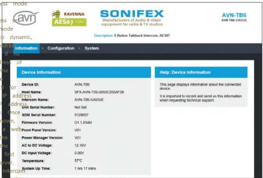
Fig 12-1: Upper Section of Device Information Web Page
This information shows the current status of the unit as well as the software versions of the various modules running on the unit. When contacting Sonifex technical support, it is important to provide the information shown on this page.
The lower half of the page shows the status of the Precision Time Protocol (PTP) clock, as well as the configuration of the network ports as shown:
| PTP Clock Information | Help: PTP Clock Information | |
| Status: | SLAVE | This section displays information about the PTP Clock. |
| Domain Number: | 0 | |
| Master ID: | 001dc1 fte 0dd4f2 | |
| Master Offset: | -46ns | |
| Ethernet Network Information | Help: Ethernet Network Information | |
| Hardware Address: | 00:50:C2:05:AF:08 | This section displays information about the Ethernet network connection (upper connector) on the connected device. The Ethernet port is used as a control port to interrogate and modify the device settings without impacting on the audio network performance. |
| Actual IP Address: | 192.168.7.4 | |
| Actual Subnet Mask: | 255.255.255.0 | |
| Address Mode: | Static | |
| Audio Network Information | Help: Audio Network Information | |
| Hardware Address: | 00:50:C2:05:AF:09 | This section displays information about the Audio over IP network connection (lower connector) on the connected device. The AoIP port is used as a data port to provide audio transfer between devices. Ideally it should not be connected to the main network as system performance may be compromised by heavy external traffic. |
| Actual IP Address: | 10.0.20.4 | |
| Actual Subnet Mask: | 255.0.0.0 | |
| Address Mode: | Static | |
Fig 12-2: Lower Section of Device Information Web Page
The network IP addresses and subnet masks shown are the actual values currently in use.
12 Embedded Web Server
Two additional pages under the information tab, provide a configuration summary of the audio and GPIO assignments.
Audio Assignments Web Page
The Audio Assignments page shows the current channel and monitor configuration as shown:
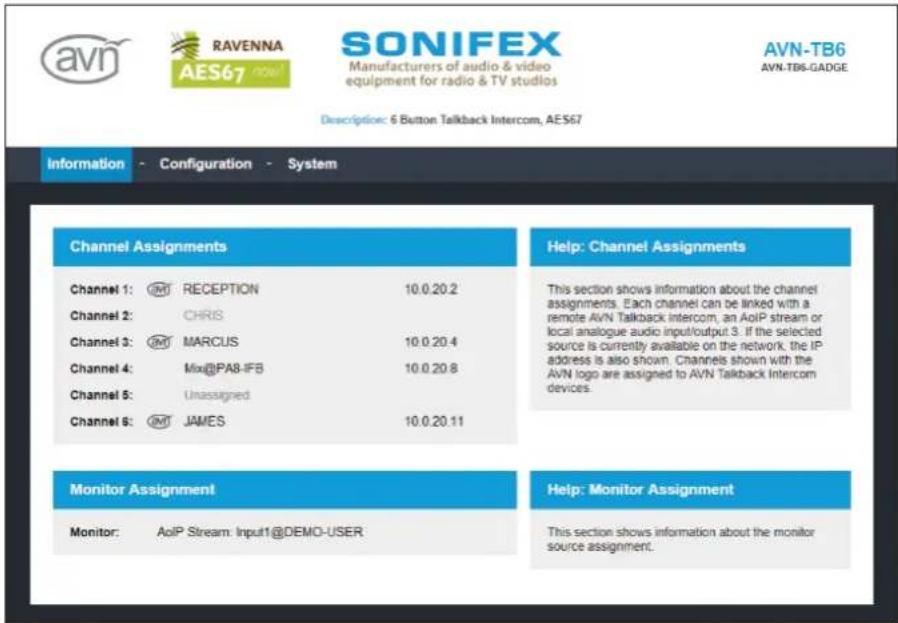
Fig 12-3: Audio Assignments Web Page
Each channel is listed with the intercom name or AoIP stream name assignment if any. Channels that are assigned to remote sources indicate whether that source is currently online. If it is online, the assignment is shown in black and the AoIP port IP address of the source is also shown. If the target assignment is an AVN talkback device, an AVN logo is shown next to the channel number. Unavailable sources or unassigned channels are shown in grey.
The Monitor Assignment shows the current configuration and status of the monitor channel. If the configured AoIP stream is currently available, the assignment is shown in black. Unavailable streams are shown in grey.
GPIO Assignments Web Page
The GPIO Assignments page shows the current GPIO, virtual GPIO and relay configuration as shown:
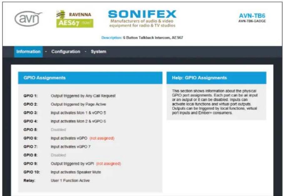
Fig 12-4: Upper Section of GPIO Assignments Web Page
Embedded Web Server 12
Each physical GPIO can be configured as an input, output or it can be disabled. Any configuration errors that will stop the GPIO functioning are shown in red. For example, GPIO 6 has been assigned as an input that activates a virtual output. However, none of the virtual GPIO have been set to an output that is driven by GPIO6. At the bottom of GPIO assignments is the list of functions that trigger the relay - if any.
12 Embedded Web Server
Each virtual GPIO can also be configured as an input, output or it can be disabled. As with the GPIO assignments, configuration errors are shown in red. Virtual inputs require a remote virtual output driver to trigger the input. The driver details are shown below the virtual input description and will be grey if the driver service is not available. If the service is available, it will be shown in black.
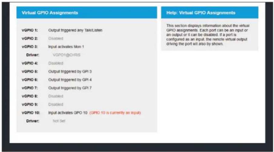
Fig 12-5: Lower Section of GPIO Assignments Web Page
Configuration Tab
The pages under the Configuration tab are split into groups and all of the unit's configuration settings can be edited here. Each page has a SUBMIT button that sends the changes to the connected unit. The SUBMIT button remains disabled until changes have been made on the page. Once the SUBMIT button has been pressed, a busy indicator will be shown and the page will be temporarily disabled until the changes have been written.
Network Web Page
The Network page shows the current configuration of the Etherne AoIP network ports. The intercom name is also set here.
Intercom Name – The intercom name is the user friendly name that identifies the unit on the network. It is a good idea to assign a user name or location as this is easily recognised by other users. The default intercom name is made from the device ID and the 7 digit product serial number i.e. AVN-TB6-1234567. The intercom name can only contain letters, numbers, and hyphens although it cannot start or end with a hyphen.
Address Mode – Each network port has its own independent address mode which determines how the port obtains its IP address. When set to dynamic, the unit will attempt to acquire an IP address automatically from either a DHCP server or via auto configuration if no DHCP server is found. The actual IP address will be shown on the device information page. When static mode is used, the IP address and subnet mask values entered will be assigned to the corresponding network port.
Static IP Address - This is the IP address that will be assigned corresponding network port when static address mode is selected. important to ensure that this IP address is not currently in use network. These values are not used when the address mode is
Static Subnet Mask - This is the subnet mask that will be used corresponding network port when static address mode is selected. values are not used when the address mode is dynamic.
Device Name
Intercom Name:
AVN-TB6-GADGE
Ethernet Network Port Settings
Address Mode:
Dynamic
Static
Static IP Address:
192.168.7.4
is found. Static Subnet Mask:
255.255.255.0
to the Audio over IP Network Port Settings

on the Address Mode:
Dynamic
Static
Static IP Address: for the
10.0.20.4
These
255.0.0.0
Auto Multicast:

SUBMIT
Fig 12-6: Network Web Page
12 Embedded Web Server
Auto Multicast - When this option is enabled and the address in AoIP port is set to static, the AoIP transmit multicast IP address the AoIP Streams Web Page, is automatically configured based on port IP address. If the IP address of the AoIP port is changed, address is updated. This simplifies configuration and ensures the n address is unique on the network.
If any of the network configuration options are changed, the unit automatically restart to implement the new settings. If the IP add network port that is currently being used to access the web service changed, a new connection will need to be made once the unit restarted. Otherwise, the new page will be shown automatically on restart is complete.
Network Defaults
Intercom Name: AVN-TB6-xxxxxxx or AVN-TB6D-xxxxxxx
Where xxxxxxx is the product serial number Fig 12-7: AoIP Stream Settings Web Page
Ethernet Port:
Address Mode: Static
Static IP Address: 192.168.0.100
Static Subnet Mask: 255.255.255.0
Audio over IP Port:
Address Mode: Static
Static IP Address: 192.168.1.100
Static Subnet Mask: 255.255.255.0
Auto Multicast: Enabled
AoIP Stream Settings Web Page
The AoIP Stream Settings page shows the current configuration of options. The single transmit source on the AVN-TB6 and AVN-TB6 the microphone/headset input.
AoIP Stream Name Prefix – The AoIP stream name prefix forms part of the AoIP stream name which will be displayed on remote devices when searching for AoIP streams. This stream name is comprised of the AoIP stream name prefix, set here for the microphone transmit source, and the intercom name. For example, if the default microphone AoIP stream name prefix "Mic" is used, and the intercom name is set to "DEMO-USER", the advertised AoIP stream name would be "Mic@DEMO-USER".
DSCP - The DSCP or Differentiated Services Code Point value is used by DiffServ to control the precedence of outgoing AoIP data packets. Network hardware can use this value to ensure audio data has higher priority over of the AoIP other network traffic. See Table 15-1 DSCP Names & Their Corresponding IP SD is for Precedence on page 52 for more information.
Multicast IP Address – The multicast IP address is the IPv4 multicast destination address for the transmit source. Remote network devices that are configured to receive this source will use this IP address to access the
audio data. It is important to ensure that the IP address entered here is
unique on the network as AoIP stream sources cannot share the
multicast IP address. Multicast IP addresses should be within the
224.0.0.0 to 239.255.255.255. If the Auto Multicast option on the
page is enabled and the AoIP port address mode is set to stat
multicast IP address is automatically configured and cannot be ch
range
Network Select:
, this
nged Reset to Defaults:
Default Profile

AoIP Stream Settings Defaults
Mic AoIP Source:
AoIP Stream Name Prefix: Mic
DSCP: AF41
Multicast IP Address: 239.0.1.100
PTP Profiles Web Page
The PTP Profiles page shows the currently selected PTP profile. It
allows the parameters in each profile to be edited.
PTP Profiles
Active Profile:
Default Profile

DSCP:
EF PHB

Fig 12-8: Upper Section of PTP Profiles Web Page
Delay Mechanism:
Announce Interval:
Announce Timeout:
Sync interval:
Delay
Request Interval:
Priority 1:
Priority 2:
Domain:
Slave Only:


E2E Delay

P2P Delay


Active Profile – There are 3 PTP profiles available: Default, AES67 Media
and Custom. This drop down list selects which of the profiles will be active.
DSCP - The DSCP or Differentiated Services Code Point value is used by SUBMIT
DiffServ to control the precedence of outgoing PTP packets. Network
hardware can use this value to ensure PTP data has higher priority 12-over Power Section of PTP Profiles Web Page
other network traffic. See Table 15-1 - DSCP Names & Their Corresponding
IP Precedence on page 52 for more information.
12 Embedded Web Server
Profile Select – This drop down list selects the profile to view settings. All of the available profiles can be edited.
Refer Delaye Request Interval – This is the rate at which a device exchanges
peer delay measurement messages. This allows each unit to track the network delays between itself and its connected neighbours. This option is not button only valid when using the P2P delay mechanism.
Reset to Defaults - Selecting this checkbox and pressing the sub resets the selected profile to the default settings for that prof
Priority 1 & Priority 2 – These values define a precedence setting used by maintaining
the best master clock algorithm when selecting a grandmaster clock.
Priority 2 defines a fine tune setting when multiple clock sources have
as are similar ordering criteria.
end on the
type of network hardware used. If all the switches are known 1588 capable, P2P should be used. Otherwise it is best to use
tDorban IEEE This defines the group of PTP devices that the unit will
cE2Emunicate with.
Announce Interval - This is the rate at which the announce m one per the selected time. The announce message forms part
e:Stage Onlyent, This option limits the unit to being a slave PTP clock only.
of the Best
PTP Profiles Defaults
Active Profile: Default
a better DSCP: AF PHB
Default Profile:
Master Clock Algorithm (BMCA) and contains the properties of which sends it. If a device receives an announce message from clock, it will enter the slave state.
Announce Timeout - This is the time the unit will wait for an announcement Delay Mechanism: E2E
message and is a multiple of announce intervals. If no announce message announce Interval: 2 secs
are received within the timeout interval, the unit will assume the role Aofnounce Timeout: 3 secs
grandmaster.
Sync Interval: 1 sec
Delay Request Interval: 1 sec
Sync Interval - This is the rate at which the sync message is sent, one per peer Delay Request Interval: 1 sec the selected time. The sync and follow up messages are sent from the peer delay request interval: 1 sec
master to the slave to determine the difference in clock frequency. This
information is used in conjunction with the network delay to synchronise
the clocks Domain: 0
Slave Only: Disabled
Delay Request Interval - This defines the rate at which a slave clock sends Media Profile:
delay request messages to the master. The delay request message allows Delay Mechanism: E2E
slave device to calculate the network delay from the slave to the master announce Interval: 2 secs
This option is only valid when using the E2E delay mechanism. Announce Timeout: 3 secs
Sync Interval: 1/8 sec
Delay Request Interval: 1 sec
Peer Delay Request Interval: 1 sec
Priority 1: 128
Priority 2: 128
Domain: 0
Slave Only: Disabled
Custom Profile:
Delay Mechanism: E2E
Announce Interval: 2 secs
Announce Timeout: 3 secs
Sync Interval: 1 sec
Delay Request Interval: 1 sec
Peer Delay Request Interval: 1 sec
Priority 1: 128
Priority 2: 128
Domain: 0
Slave Only: Disabled
Basic Channel Settings
Available AoIP Sources: Select a device or stream...

1: RECEPTION
2: CHRIS
3: MARCUS
4: Mix@PA8-IFB
5:
6: JAMES
ASSIGN
ASSIGN
ASSIGN
ASSIGN
ASSIGN
ASSIGN
SUBMIT
Channels - Basic Settings Web Page
The Basic Settings page is located under the Channels sub tab. It allows the
AoIP stream source assignments to be set for all 6 channel buttons on the Fig.12-10: Channels - Basic Settings Web Page
front panel. The other channel options are shown on the Channels
Advanced Settings web page - see page 30 for details.
Available AoIP Sources – This dynamic drop down list shows the 3 to AoIP sources that are currently visible on the network and available selection as a target for a channel. These types are AVN Intercom AVN Intercom Devices with IFB and AoIP Streams. To make an assign select a source from the list and then press the assign button on channel.
Channels 1 - 6 - Each row shows the current AoIP source assignment corresponding channel. To change the stream name, select a source of Available AoIP Sources list and press the assign button on the required channel. Alternatively, the stream name can also be entered manually remote sources that are currently offline.
12 Embedded Web Server
Channels - Basic Settings Defaults
Channels 1 - 6:
AoIP Source: not set
Channels - Advanced Settings Web Page
The Advanced Settings page is located under the Channels sub shows the current assignments for each of the 6 channel butt front panel. Other options that control intercom calls are also
Channel Select - This drop down list selects the channel to view and change settings.
AoIP Source - This setting assigns the intercom name or AoIP stream name to connect to when the intercom channel is active. If the source is an intercom device, this name corresponds to the intercom name that is tab it
assigned on the network web page. This name can be entered manually, or its on the it can be selected from the dynamic list of available AoIP sources detailed et here. below.
Advanced Channel Settings
Channel Select:
Channel 3

AoIP Source:
MARCUS
Available
Select a device or stream...

AoIP Sources:
IFB Mode:

IFB Source:
IFB2
Available
Select an IFB source...

IFB Sources:
Auto Answer:

Default Function:
Talk & Listen

Button Mode:
Auto

Call Signal:

SUBMIT
Fig 12-11: Channels - Advanced Settings Web Page
Available AoIP Sources – This dynamic drop down list shows the 3 types of AoIP sources that are currently visible on the network and available for selection as a target for a channel. These types are AVN Intercom Devices, AVN Intercom Devices with IFB and AoIP Streams. Selecting an AoIP source from this list places the name into the AoIP source edit box.
IFB Mode - This option allows the selected channel to be assigned to an AoIP stream from a remote intercom device. This stream type will have a designated audio feed that will be replaced by or mixed with the microphone audio when the channel is active. If IFB mode for the channel enabled and the AoIP source is an available intercom device, but the configured IFB stream does not exist, a non IFB mode call will be connected instead.
IFB Source - This is the AoIP stream name prefix of the IFB stream on the selected AoIP Source. This name can be entered manually, or it can be selected from the dynamic list of available IFB sources detailed below. This option is only available if IFB mode is enabled.
Available IFB Sources - This dynamic drop down list shows the names of the available IFB streams on the selected AoIP source. If the selected AoIP source is not an IFB enabled intercom device, this list will be empty. This option is only available if IFB mode is enabled.
Auto Answer - This option allows an incoming call on the selected group channel Web Page
to be answered automatically without the need to press the associated group Talk page shows the channels that are included in the g channel button.
Default Function - The default function option sets the call type that is
initiated when the corresponding channel button is pressed. Talk & Listep Talk calls allow both the caller and receiver hear each other. In a Talk Only call, only the receiver hears the caller. In a Listen Only call, only the caller hears the receiver. Talk Forced Listen calls allow the caller to hear the receiver, with the option to enable or disable talk to the receiver by repeatedly pressing the channel button. If IFB mode is enabled on the selected channel, Talk Forced Listen is not available. The default function can be overridden when initiating call by using the listen button on the front panel.
Button Mode – Selects the operational mode of the selected channel talk button. In momentary mode, the channel is active whilst the button is pressed. In latching mode, a separate button press is required to enable and disable the channel. In auto mode, the button has a momentary action that will automatically latch on or off if pressed briefly. The button can also be disabled if required. Momentary mode is not available if auto answer is enabled.
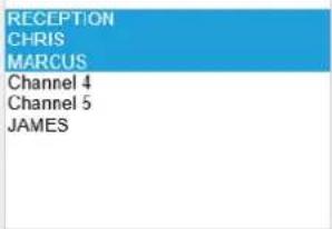
Fig 12-12: Group Talk Web Page
Call Signal - This option enables an audible indication that an incoming call is waiting to be answered. The call signal is heard through the ChannelsakerClick on this list to select the channels that are to be or the headphones if connected. This setting applies to all channels. group talk set. To select multiple channels, hold down the Ctrl the keyboard and then make a selection.
Channels - Advanced Settings Defaults
Channels 1 - 6:
AoIP Source: Not set
IFB Mode: Disabled
IFB Source: Not set
Auto Answer: Disabled
Default Function: Talk & Listen
Button Mode: Auto
Call Signal: Enabled
Group Talk Defaults
Channels: 1, 2, 3, 4, 5, 6
12 Embedded Web Server
Front Panel - Display Settings Web Page
The Display Settings page is located under the Front Panel sub the LED brightness to be adjusted.
Display Settings
LED Brightness:

SUBMIT
Fig 12-13: Front Panel - Display Settings Web Page
LED Brightness - Click on the + or - buttons to change the brightness of the LEDs on the front panel in the range 1 to 7.
Front Panel - Display Settings Defaults
LED Brightness: 4
Front Panel - Colour Settings Web Page
Table. Colour settings page is located under the Front Panel sub tab. It shows the colours that are assigned to the intercom call and user buttons as shown:
Colour Settings
Talk Buttons:

Listen Buttons:

Talk & Listen Buttons:
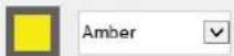
User Button:

SUBMIT
Fig 12-14: Front Panel - Colour Settings Web Page
Talk Buttons - This setting defines the colour of the channel buttons when a talk only call is active.
Listen Buttons - This setting defines the colour of the channel buttons when a listen only call is active.
Talk & Listen Buttons - This setting defines the colour of the channel buttons when a talk & listen call is active.
User Button - This setting defines the colour of the user assignable function button.
Embedded Web Server 12
Front Panel - Colour Settings Defaults
Talk Buttons: Red
Listen Buttons: Green
Talk & Listen Buttons: Amber
User Button: Blue
Front Panel - User Button Settings Web Page
The User Button Settings page is located under the Front Panel shows the configuration of the user button.
User Button
Function:
GPO Control

Button Mode:
Auto

SUBMIT
Fig 12-15: Front Panel - User Button Settings Web Page
Function - This option sets the function for the user button. Group initiates a group talk call to the members of the group talk set. G allows a selection of physical and virtual GPO ports to be asserted, and virtual GPO ports that are under user button control are assigned GPIO and virtual GPIO settings pages.
Button Mode - Selects the operational mode of the selected user bu In momentary mode, the selected user function is active whilst the is sub tab. It in latching mode, a separate button press is required to and disable the selected user function. In auto mode, the button has momentary action that will automatically latch on or off if pressed by The button can also be disabled if required.
Front Panel - User Button Defaults
User Button:
Function: Group Talk
Button Mode: Auto
12 Embedded Web Server
Audio - Microphone Settings Web Page
The Microphone Settings page is located under the Audio sub microphone input type and associated options are set here.
Microphone Settings
Microphone Type:
Mic with Phantom

Gain Control:
Auto Gain

Mic Gain:


AGC Target Level:
-12dBFS

Auto Mute:

Mute Button Mode:
Auto

SUBMIT
Fig 12-16: Audio - Microphone Settings Web Page
Microphone Type - This drop down list selects the required microphone input type and also enables phantom power if required.
Gain Control - This option selects between fixed or auto gain control. When auto gain is selected, the gain levels for the mic and headset inputs are automatically adjusted to compensate for varying talk levels.
Mic Gain - This option sets the input gain for the mic in the range 0dB tab60dB in 3dB steps.
Headset Gain - This option sets the input gain for the headset in the range 0dB to +60dB in 3dB steps.
AGC Target Level – This option sets the required output level for the microphone/headset automatic gain control. This option is available only when the gain control is set to auto gain.
Auto Mute - This option selects whether the microphone or headset AoIP stream is automatically muted when no calls are active. Please note, if this option is not enabled, the audio from the microphone or headset will be available to any other devices on the network.
Mute Button Mode - Selects the operational mode of the mic mute button on the front panel. In momentary mode, the mic mute is active whilst the button is pressed. In latching mode, a separate button press is required to enable and disable the mic mute function. In auto mode, the button has a momentary action that will automatically latch on or off if pressed briefly. The button can also be disabled if required.
Audio - Microphone Settings Defaults
Microphone Type: Normal Mic
Gain Control: Fixed Gain
Mic Gain: 30
Headset Gain: 30
AGC Target Level: -18dBFS
Auto Mute: Enabled
Mute Button Mode: Auto
Embedded Web Server 12
Audio - Monitor & Speaker Settings Web Page
The Monitor & Speaker Settings page is located under the Award and it shows the current assignment for the monitor channel. loudspeaker options are also set here.
Monitor Settings
AolP Stream:
Input1@JAMES
Available
AoIP Streams:
select stream

Talkback Mode:
Mute

Button Mode:
Auto

Speaker Settings
Echo Cancellation:

Mute Button Mode:
Auto

SUBMIT
Fig 12-17: Audio - Monitor & Speaker Settings Web Page
AoIP Stream - This setting is the name of the AoIP stream that was routed to the monitor channel. The stream name is comprised of the stream name prefix and the intercom name. For example, if the req AoIP stream, called "Input1", is being transmitted from an intercom with the name "DEMO-SOURCE", the AoIP stream name would be "Input1@DEMO-SOURCE". This name can be entered manually, or it can be selected from the dynamic list of available AoIP streams detailed below
Available AoIP Streams – This dynamic drop down list shows the AoIP streams that are currently visible on the network. Selecting an AoIP from this list places the name into the AoIP stream edit box.
Talkback Mode - This setting controls how the audio level of the m modified when an intercom channel is active. There are 3 options, t of the monitor is either muted, reduced by 75% or reduced by 50%
Button Mode - Selects the operational mode of the monitor button (front panel. In momentary mode, the monitor is active whilst the button pressed. In latching mode, a separate button press is required to enable and disable the monitor. In auto mode, the button has a momentar that will automatically latch on or off if pressed briefly. The button be disabled if required.
Echo Cancellation - This setting enables the acoustic echo cancellation algorithm which removes audio content, originating from the speaker, the microphone input. This prevents a remote user from hearing a echo of themselves.
Mute Button Mode - This setting selects the operational mode of the speaker mute button on the front panel. In momentary mode, the s is muted whilst the button is pressed. In latching mode, a separate press is required to enable and disable the speaker mute. In auto i button has a momentary action that will automatically latch on or o pressed briefly. The button can also be disabled if required with the permanently on or off.
12 Embedded Web Server
Audio - Monitor & Speaker Settings Defaults
AoIP Stream: not set
Talkback Mode: Mute
Button Mode: Auto
Echo Cancellation: Disabled
Mute Button Mode: Auto
Page Settings Web Page
The Page Settings page shows the current list of target page function. The page priority setting is also set here.
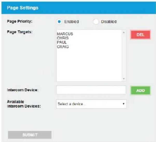
Fig 12-18: Page Settings Web Page
Page Priority – This option selects whether received page calls have priority over current intercom calls. If this option is enabled, all current intercom calls will be suspended during a received page call. These calls will then resume once the page call has ended. If a page request is received and option is disabled, the page will be ignored.
Page Targets - This is the list of up to 20 target intercom devices that was called during a page. To add to the list, select a new device from the available intercom devices select box or manually enter the name in the intercom devices edit and then press the ADD button. To remove one or more targets from the list, highlight the required page targets and press the DEL button. Multiple targets can be selected by clicking the required options whilst holding down the Ctrl key on the keyboard.
Intercom Device - A new page target intercom name can be added to the list by entering the name in this edit box and pressing the ADD button. Alternatively, it can be selected from the dynamic list of available intercom devices detailed below.
Available Intercom Devices - This dynamic drop down list shows the intercom units that are currently visible on the network and available for selection as a page target. Selecting an intercom from this list places the intercom name into the intercom device edit box.
Page Settings Defaults
Page Priority: Enabled
Page Targets: none set
Embedded Web Server 12
GPIO Settings Web Page
The GPIO Settings page shows the current configuration of the ports on the rear panel mounted GPIO connector. The functions, states that control the output relay are also set here.
GPIO Settings
GPIO Select:
Port 1
Type:
Input
Input Function:
Speaker Mute
Input Action:

Momentary

Latching
Relay Settings
Relay Trigger:
Vital of the
Virtual GPI 6
Virtual GPI 7
Virtual GPL 8
Virtual OPIC
Virtual GPTS
Virtual GPI 10
AC PSU Warn
DC PSU Warn
Embeet Consumer
SUBMIT
Fig 12-19: GPIO Settings Web Page
GPIO Select - This drop down list selects the GPIO port to view an setting
inputs and
Type - This option selects whether the selected GPIO port is an input output or whether it is disabled. Ports configured as inputs are active and they have a weak internal pullup. Ports configured as outputs a collector driven and are therefore active low.
Input Function - This option selects the required function that the set GPIO input controls. GPIO inputs can be set to control a local func virtual GPIO output if required. If no local function control is needed control of a virtual GPIO output is required, select Virtual GPIO Only assignment for which GPIO input triggers a virtual GPIO output is m the virtual GPIO settings page. This option is only available when the set to input.
Input Action - This option selects the operational mode of the select GPIO input. In momentary mode, the selected function is active while input is asserted low. In latching mode, a separate active low pulse required to enable and disable the selected function. This option is available when the type is set to input.
Output Trigger - This option selects the function that triggers the GP output. GPIO outputs can be triggered by a local function, a virtual input and an Ember+ consumer if required. If a local function trigger needed, but a virtual GPIO input or Ember+ consumer trigger is required to select Virtual GPI Only or Ember+ Consumer Only. The assignment for virtual GPIO input triggers a GPIO output is made on the virtual GP settings page. This option is only available when the type is set to
Relay Trigger - The output relay, which provides both normally open normally closed contacts on the GPIO connector on the rear panel, triggered by multiple functions, inputs and states. When any of the triggers become active, the relay is switched on. To select multiple click on the required options whilst holding down the Ctrl key on t
12 Embedded Web Server
keyboard. The CLEAR ALL button provides an easy way to remove GPIO Selectt- This drop down list selects the virtual GPIO port to view a relay trigger assignments. change settings.
GPIO Settings Defaults
GPIO Port 1 - 10:
Type: Disabled
Input Function: Talk/Listen 1
Input Action: Latching
Output Trigger: Talk/Listen 1
Virtual GPIO Settings Web Page
The Virtual GPIO Settings page shows the current configuration of the input driver source – This setting is the name of the virtual GPIO output of virtual GPIO ports. These virtual ports provide a method of controlling remote unit that will drive the virtual GPIO input on this unit. These functions on remote units by linking a virtual output on one unit to source name are generated automatically based on the source type and input on another unit.
Virtual GPIO Settings
vGPIO Select:
Virtual Port 1

Type:
Input

Input Function:
Monitor 1

Input Driver Source:
VGPO1@CHRIS
Available vGPO Sources:
.select source
SUBMIT
Fig 12-20: Virtual GPIO Settings Web Page
Type - This option selects whether the selected virtual GPIO port is an input, an output or whether it is disabled.
Input Function - This option selects the required function that the selected virtual GPIO input controls. This list includes GPO 1 - 10 which allows a virtual GPIO input to control a physical GPIO output. Please note, if a GPIO port is selected, the type option for that GPIO port must be set to output. This option is only available when the type is set to input.
The Driver Source - This setting is the name of the virtual GPIO output or a remote unit that will drive the virtual GPIO input on this unit. These source names are generated automatically based on the source type and the intercom name. For example, for virtual output port 1 on an intercom unit with the name "DEMO-SOURCE", the source name would be "VGPO1@DEMO-SOURCE". This name can be entered manually, or it can be selected from the dynamic list of available vGPO sources detailed below. This option is only available when the type is set to input.
Available vGPO Sources – This dynamic drop down list shows the virtual GPIO outputs that are currently visible on the network and available for selection as an input driver source. Selecting a source from this list places the virtual GPIO output name into the input driver source edit box. This option is only available when the type is set to input.
Output Trigger - This option selects the function that triggers the virtual GPIO output. This list includes GPI 1 - 10 which allows a physical GPIO to trigger a virtual GPIO output. Please note, if a GPI port is selected, the type option for that GPIO port must be set to input otherwise the virtual output will not be triggered. This option is only available when the type is set to output.
Embedded Web Server 12
Virtual GPIO Settings Defaults
Virtual GPIO Port 1 - 10:
Type: Disabled
Input Function: Talk/Listen 1
Input Driver Device: not set
Output Trigger: Talk/Listen 1
Miscellaneous Settings Web Page
The Miscellaneous Settings page shows general settings for the unit.
Miscellaneous Settings
Power Button:

Enable

Disable
AC PSU Status:

Enable

Disable
DC PSU Status:

Enable

Disable
Auto Save on Page Exit:

Enable
SUBMIT
Fig 12-21: Miscellaneous Settings Web Page
Power Button - This option enables the power button on the the unit. When enabled, pressing the power button will switch and off.
AC PSU Status - This option enables the AC PSU status LED on the panel.
DC PSU Status - This option enables the DC PSU status LED on the panel.
Auto Save on Page Exit - With this option enabled, any changes made page are automatically saved when leaving the page. This option is cleared when connecting to a device.
onnected
Miscellaneous Settings Defaults
Power Button: Enabled
AC PSU Status: Enabled
DC PSU Status: Enabled
System Tab
The System Tab allows the firmware on the unit to be updated. It options for saving and loading the configuration settings to and from file.
Update Firmware
Update Firmware
Please visit our software downloads page for firmware updates.
Current Firmware Version: D1.1.834M

panel of
Fig 12-22: Update Firmware Section of System Web Page
12 Embedded Web Server
The current firmware version on the connected unit is shown. Next vConfiguration From A File of firmware will be released as new features are added, and when any bug
fixes are completed. Click on the software downloads link to visit thead Configuration From A File
Sonifex web page. If an update is available, download the latest file. The file
will have the '.SWU' extension. Click the select button and browse Oyourrite Network Settings:
computer to locate the new firmware file and then click Update. Once the
file has been successfully uploaded to the unit, the firmware update
process will begin. This takes approximately 1 minute during which time a
progress page will be shown. Once the update is complete, the device
information page will be shown automatically.
Browse..
Save Configuration To A File
Save Configuration To A File
SAVE CONFIG
Fig 12-23: Save Configuration Section of System Web Page
Fig 12-24: Load Configuration Section of System Web Page
The current configuration of the connected unit can be overwritten from a previously saved xml file. The settings on the network page will only be updated if the Overwrite Network Settings check box is ticked. Click the select button and browse your computer to locate the required configuration file and then click the LOAD CONFIG button. Once the file has been successfully uploaded, the unit will automatically reboot to load the new configuration settings. This takes approximately 25 seconds during which time a progress page will be shown. If the settings of the network
The current configuration of the connected unit can be saved to port label browser is connected to have changed, a new connection will need file by clicking the SAVE CONFIG button. The filename will be "bn_b" made once the unit has restarted. Otherwise, the device information followed by the intercom name. It is a good idea to save the pagefiguration shown automatically.
settings of all units on the network once they have been setup as this
provides a quick and easy way of returning the units to a known working condition.
Save System Log To A File
Save System Log To A File
SAVE LOG
Fig 12-25: Save System Log Section of System Web Page
The AVN-TB6 and AVN-TB6D maintain an internal log that records system events and errors. This information may be useful for resolving configuration issues. To download the log, click the SAVE LOG button.
13 Ember+ Interface
13. Ember+ Interface
The AVN-TB6 and AVN-TB6D have an Ember+ provider interface exposes all of the available configuration options. It also allows virtual GPIO and the relay to be controlled and monitored by Ember+ consumer.
Connecting to the Ember+ Interface
The Ember+ interface is available on both the Ethernet and AoIP connections using port 9000. Each of the configuration options are arranged in branches grouped by function. Fig 13-1 shows a graph representation of the root structure.
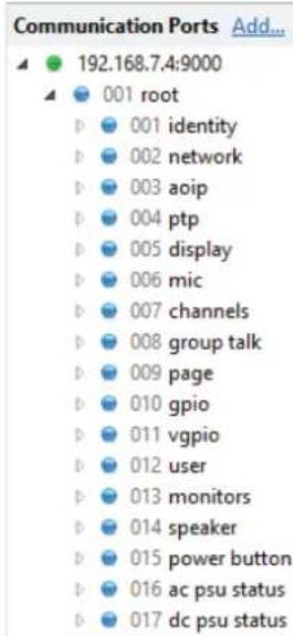
treemap
Communication Ports Add... | Node | Value | |---|---| | root | 192.168.7.4:9000 | | identity | 001 | | network | 002 | | aoip | 003 | | ptp | 004 | | display | 005 | | mic | 006 | | channels | 007 | | group talk | 008 | | page | 009 | | gpio | 010 | | gpio | 011 | | user | 012 | | monitors | 013 | | speaker | 014 | | power button | 015 | | ac psu status | 016 | | dc psu status | 017 |Fig 13-1: Ember+ Root Structure
The configuration options are presented as either string or integer types. Where possible, integer type options are enumerated to indicate what each that of the setting values are. A full list of the options and values associated the GPIO, each of the Ember+ parameters are on page 45. an external
GPIO
The GPIO branch of the Ember+ provider interface allows monitoring and control of the GPIO ports and the relay. Fig 13-2 shows the structure of each GPIO child node. For further details on the configuration options, refer to page 37.
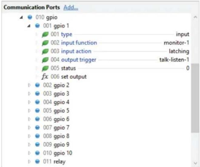
Fig 13-2: Ember+ GPIO Branch Structure
Each GPIO node has a similar set of parameters and functions:
Type Parameter
This enumerated integer parameter is the current port type.
Input Function Parameter
This enumerated integer parameter is the function that will be when the GPIO port, when configured as an input, is asserted.
Input Action Parameter
This enumerated integer parameter is the operational mode of the GPIO port when it is configured as an input.
Output Trigger Parameter
This enumerated integer parameter is the function that triggers port when it is configured as an output.
Status Parameter
The status parameter shown in Fig 13-2 represents the current GPIO port regardless of whether the port is set as an input value of 0 indicates the port is inactive and a 1 indicates the This parameter has an Ember+ stream identifier and a consumer subscribe to it to automatically receive updates when the status
Set Output Function
The set output leaf shown in Fig 13-2 is a function that allows control of the Active Function
GPIO port when it is configured as an output. The function exposes 1 argument called enable, which is an integer with a value of non-zero for relay. The function exposes 1 argument called enable, which is an integer with a value of non-zero to activate the relay, or zero to de-activate results. The function also returns an integer result which reflects the current state of the GPIO output. The function also returns an integer result which reflects the error in the status parameter. A return value of -1 indicates there was an error invoking the function. If the GPIO port is configured as an input, it indicates there was an error invoking the function.
Relay
The relay node of the GPIO branch of the Ember+ provider interface the relay to be controlled by an Ember+ consumer. Fig 13-3 shows structure of the relay node. For further details on the configuration refer to page 37
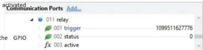
Fig 13-3: Ember+ Relay Node Structure
the GPIO Trigger Parameter
This integer parameter is the combined value of the functions that the operation of the relay. As multiple trigger functions can be selected value shown is the sum of the selected items corresponding values. state of the
or an output. A Status Parameter
- port is active. The status parameter shown in Fig 13-3 represents the current state can relay. A value of 0 indicates the relay is inactive and a 1 indicates changes. Active: This parameter has an Ember+ stream identifier and a consum subscribe to it to automatically receive updates when the status chan
13 Ember+ Interface
Virtual GPIO Control
The virtual GPIO branch of the Ember+ provider interface allows this string parameter is the name of the virtual output on a remote unit and control of the virtual GPIO ports. Fig 13-4 shows the structure of each that drives the virtual GPIO port when it is configured as an input.
virtual GPIO child node. For further details on the configuration refer to page 38.
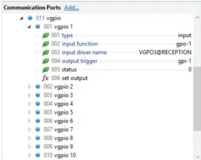
Fig 13-4: Ember+ Virtual GPIO Branch Structure
Input Driver Name Parameter
This string parameter is the name of the virtual output on a remote unit that drives the virtual GPIO port when it is configured as an input.
options, Output Trigger Parameter
This enumerated integer parameter is the function that triggers the GPIO port when it is configured as an output.
Status Parameter
The status parameter shown in Fig 13-4 represents the current state of the virtual GPIO port regardless of whether the port is set as an input or an output. A value of 0 indicates the port is inactive and a 1 indicates the is active. This parameter has an Ember+ stream identifier and a consumer can subscribe to it to automatically receive updates when the status changes.
Set Output Function
The set output leaf shown in Fig 13-4 is a function that allows control of virtual GPIO port when it is configured as an output. To use this function, the output trigger must be set to ember-consumer, and at least one remot unit must have this output selected as the driver for a virtual input. The function exposes 1 argument called enable, which is an integer with a value of non-zero for assert the output, or zero for de-assert the output. The function also returns an integer result which reflects the current state of the virtual GPIO output similar to the status parameter. A return value of indicates there was an error invoking the function. If the virtual GPIO port configured as an input, invoking this function has no effect.
Type Parameter
This enumerated integer parameter is the current virtual GPIO port type.
Input Function Parameter
This enumerated integer parameter is the function that will be activated when the virtual GPIO port, when configured as an input, is asserted.
Parameter Value Specification
This section provides a full list of the possible par values for the Ember+ interface. Integer values with prefix are in hexadecimal format.
Identity
This is a read only leaf that describes the unit.
Network
Intercom Name (string): Max length = 23 characters Address Mode (integer): 0 = Dynamic, 1 = Static IP Address (string): Max length = 15 characters Subnet Mask (string): Max length = 15 characters Auto Multicast (integer): 0 = Disable, 1 = Enable
AoIP
Stream Name (string): Max length = 12 characters DSCP (integer): Min = 0, Max = 56 IP Address (string): Max length = 15 characters
PTP
DSCP (integer): Min = 0, Max = 56
Profile, (integer): 0 = Default
1 = AES67 Media
2 = Custom
Domain Number (integer): Min = 0
Max = 127 (Default Profile)
Max = 255 (AES67 Media Profile)
Max = 255 (Custom Profile)
Priority 1 (integer): Min = 0, Max = 255
Priority 2 (integer): Min = 0, Max = 255
Announce Interval (integer): Setting value ^integer 2
Min = 0 (Default Profile)
Min = 0 (AES67 Media Profile)
Min = -3 (Custom Profile)
Max = 4
Announce Timeout (integer): Min = 2, Max = 10
Sync Interval (integer): Setting value ^intags 2
Min = -1, Max = 1 (Default Profile)
Min = -4, Max = 1 (AES67 Media Profile)
Min = -7, Max = 6 (Custom Profile)
Min Delay Request Interval (integer): Setting value is 2
Min and Max values in following read
only parameters
Min Delay Request Interval Min (integer): Value is read only
Greater of 0 or Sync Interval (Default Profile)
Greater of -3 or Sync Interval (AES67 Media Profile)
Sync Interval (Custom Profile)
Min Delay Request Interval Max (integer): Value is read only:
13 Ember+ Interface
Lesser of 5 or Sync Interval+5
(Default Profile)
Lesser of 5 or Sync Interval+5
(AES67 Media Profile)
Sync Interval+5 (Custom Profile)
Min Peer Delay Request Interval (integer): Setting value is 2
Min = 0, Max = 5 (Default Profile)
Min = 0, Max = 5 (AES67 Media Profile)
Min = -1, Max = 5 (Custom Profile)
Slave Only (integer): 0 = Disable, 1 = Enable
Delay Mechanism (integer): 0 = E2E, 1 = P2P
Reset Defaults (integer): 1 = Reset Profile to Default Values

Display
LED Brightness (integer): Min = 1, Max = 7
Talk Colour,
Listen Colour,
Talk Listen Colour,
User 1 Colour (integer): 0 = Red
1 = Green
2 = Amber
3 = Blue
4 = Purple
5 = Light Blue
6 = White
Mic
Type (integer): 0 = Mic
    1 = Phantom Mic
    2 = Headset
    3 = Phantom Headset
Gain Control (integer): 0 = Fixed, 1 = Automatic
Mic Gain (integer): Actual Gain is value x 3
    Min = 0, Max = 20
Headset Gain (integer): Actual Gain is value x 3
    Min = 0, Max = 20
AGC Target Level (integer): 0 = -24dBFS
    1 = -21dBFS
    2 = -18dBFS
    3 = -15dBFS
    4 = -12dBFS
    5 = -9dBFS
    6 = -6dBFS
Auto Mute (integer): 0 = Disable, 1 = Enable
Mute Button Mode (integer): 0 = Auto
    1 = Momentary
    2 = Latching
    3 = Disabled On
    4 = Disabled Off
Channels
AoIP Source (string): Max length = 36 characters
IFB Mode (integer): 0 = Disable, 1 = Enable
IFB Source (string): Max length = 12 characters
Auto Answer (integer): 0 = Disable, 1 = Enable
Default Function (integer): 0 = Talk & Listen
1 = Talk Only
2 = Listen Only
3 = Talk Forced Listen
Button Mode (integer): 0 = Auto
1 = Momentary
2 = Latching
3 = Disabled
Call Signal (integer): 0 = Disable, 1 = Enable
Group Talk
Group Talk 1 (integer): Value is sum of required options
0x1 = Channel 1
0x2 = Channel 2
0x4 = Channel 3
0x8 = Channel 4
0x10 = Channel 5
0x20 = Channel 6
Page
Priority (integer): 0 = Disable, 1 = Enable
Target 1,
Target 2,
Target 3,
Target 4,
Target 5,
Target 6,
Target 7,
Target 8,
Target 9,
Target 10,
Target 11,
Target 12,
Target 13,
Target 14,
Target 15,
Target 16,
Target 17,
Target 18,
Target 19,
Target 20 (string): Max length = 23 characters
GPIO
Type (integer): 0 = Input
1 = Output
2 = Disabled
Input Function (integer): 0 - 5 = Talk/Listen 1 - 6
6 = Page
7 = User Button 1
8 = Monitor 1
9 = Speaker Dim
10 = Speaker Mute
11 = Microphone Mute
12 = Virtual GPO Only
Input Action (integer): 0 = Momentary
1 = Latching
Output Trigger (integer): 0 - 5 = Talk/Listen 1 - 6
6 = Any Talk/Listen
7 - 12 = Call Request 1 - 6
13 = Any Call Request
14 = Page
15 = User Button 1
16 = Monitor 1
17 = Speaker Dim
18 = Speaker Mute
19 = Microphone Mute
20 = Virtual GPI Only
21 = Ember+ Consumer Only
13 Ember+ Interface
Relay
Trigger (integer): Value is sum of required options
0x1 = Talk/Listen 1
0x2 = Talk/Listen 2
0x4 = Talk/Listen 3
0x8 = Talk/Listen 4
0x10 = Talk/Listen 5
0x20 = Talk/Listen 6
0x40 = Call Request 1
0x80 = Call Request 2
0x100 = Call Request 3
0x200 = Call Request 4
0x400 = Call Request 5
0x800 = Call Request 6
0x1000 = Page
0x2000 = User Button 1
0x4000 = Monitor 1
0x8000 = Speaker Dim
0x10000 = Speaker Mute
0x20000 = Mic Mute
0x40000 = GPI 1
0x80000 = GPI 2
0x100000 = GPI 3
0x200000 = GPI 4
0x400000 = GPI 5
0x800000 = GPI 6
0x1000000 = GPI 7
0x2000000 = GPI 8
0x4000000 = GPI 9
0x8000000 = GPI 10
0x10000000 = Virtual GPI
0x20000000 = Virtual GPI
0x40000000 = Virtual GPI
0x80000000 = Virtual GPI
0x100000000 = Virtual GPI
0x20000000
0x400000000 = Virtual GPI 7
0x800000000 = Virtual GPI 8
0x1000000000 = Virtual GPI 9
0x2000000000 = Virtual GPI 10
0x4000000000 = AC PSU Warn
0x8000000000 = DC PSU Warn
0x10000000000 = Ember+ Consumer
vGPIO
Type (integer): 0 = Input
1 = Output
2 = Disabled
Input Function (integer): 0 - 5 = Talk/Listen 1 - 6
6 = User Button 1
7 = Monitor 1
8 = Speaker Dim
9 = Speaker Mute
10 = Microphone Mute
11 - 20 = GPO 1 - 10
Input Driver Name (string): Max length = 30 characters
Output Trigger (integer): 0 - 5 = Talk/Listen 1 - 6
6 = Any Talk/Listen
7 - 12 = Call Request 1 - 6
13 = Any Call Request
14 = Page
15 = User Button 1
16 = Monitor 1
17 = Speaker Dim
18 = Speaker Mute
19 = Microphone Mute
20 - 29 = GPI 1 - 10
30 = Ember+ Consumer
User
Function (integer): 0 = Group Talk
1 = GPO Control
Button Mode (integer): 0 = Auto
1 = Momentary
2 = Latching
3 = Disabled
Monitors
AoIP Stream (string): Max length = 36 characters
Talkback Mode (integer): 0 = Mute
    1 = Dim 75%
    2 = Dim 50%
Button Mode (integer): 0 = Auto
    1 = Momentary
    2 = Latching
    3 = Disabled
Speaker
Echo Cancel (integer): 0 = Disable, 1 = Enable
Mute Button Mode (integer): 0 = Auto
    1 = Momentary
    2 = Latching
    3 = Disabled On
    4 = Disabled Off
Power Button
Enable (integer): 0 = Disable, 1 = Enable
AC PSU Status
Enable (integer): 0 = Disable, 1 = Enable
DC PSU Status
Enable (integer): 0 = Disable, 1 = Enable
14 Technical Specifications
14. Technical Specifications
Audio-Over-IP Specification
| Open Standards: RAVENNA, AES67 |
| Device Discovery: Bonjour (mDNS / DNS-SD) |
| Audio Delivery: RTP/UDP over IPv4 multicast |
| QoS: DiffServ |
| Stream Management: RTSP/SDP |
| Control: Web server/Ember+ |
| Format: Linear PCM 24-bit (L24) |
| Channels Per Stream: 2 |
| Frames Per Packet: 48 |
| Transmit Streams: 1 (fixed) |
| Sample Rate: 48 kHz |
Ember+ Interface Connection
| Interface Type: | Provider |
| Network Interface: | Ethernet port and AoIP port |
| Port: 9000 |
Timing Synchronisation
| Profile | Support: | Default, AES67 | Media & Custom profiles |
| Timing | Protocol: | PTPv2, IEEE1588-2008 |
Microphone and Headset Input
| Input Impedance: > 2.5kΩ balanced | |
| Gain Range: | 0dB to +60dB |
| 0dBFS Line-Up: | Adjustable in steps of 3dB from -58dBu+2dBu |
| Frequency Response: | 20Hz to 20kHz, +0/-0.2dB |
| Noise: | -127dBu, 20kHz BW, Rs=200Ω ref. 76dB gain |
Headphone Output
| Output Impedance: | Drives 150mW into 32Ω to 600Ω headphones |
| 0dBFS Line-Up: +20dBu | |
| Frequency Response: | 20Hz to 20kHz, +0/-0.2dB |
| THD+N: < -108dBFS, gain, 20kHz BW | |
| Noise: | -110dBFS, 20kHz BW |
Loudspeaker
| Power Output: | 4W |
| Volume: | Mute to full volume via front panel control |
Connections
| Microphone: | XLR-3 pin female (electronically balanced) |
| Headphone: | 14 inch (6.35mm) stereo jack socket |
| Headset: | 1 x XLR-5 pin female (electronically balanced input) |
| GPIO: | 15-way ‘D’-type socket |
| Network: | 2 x gigabit Ethernet, RJ45 1 x SFP |
| Mains AC Input: | Universal filtered IEC, continuously rated 85-264VAC, 47-63Hz, 20W |
| DC Input: | 4 pin 7.5A power jack socket, 10-14VDC |
| Fuse Rating: | Anti-surge fuse 2A 20mm x 5mm |
Equipment Type
| AVN-TB6: | 6 channel freestanding talkback intercom control unit with RAVENNA AoIP |
| o | |
| AVN-TB6D: | 6 channel desktop talkback intercom control unit with RAVENNA AoIP |
Physical Specification AVN-TB6
| Dimensions (Raw): 25.5cm (W) x 19.4cm (D) x 4.4cm (H) (1U) |
| Dimensions (Boxed): |
| Weight: 33cm (W) x 26cm (D) x 17cm (H) |
| 13" (W) x 10.3" (D) x 6.7" (H) |
Accessories
| AVN-DC150: 150W DC power supply with KPJX-4S plug |
| AVN-TB6RK: 1U rack-kit for AVN-TB6RK |
15 Additional Information
15. Additional Information
| DSCP Name DS Field Value IP Precedence (Description) | |
| CS0 0: Best effort | |
| CS1, AF11-AF13 8, 10, 12, 14 1: Priority | |
| CS2, AF21-AF23 16, 18, 20, 22 2: Immediate | |
| CS3, AF31-AF33 24, 26, 28, 30 3: Flash (mainly used for vo signalling) | |
| CS4, AF41-AF43 32, 34, 36, 38 4: Flash Override | |
| CS5, EF PHB 40, 46 5: Critical (mainly used for RTP) | |
| VOICE ADMIT 44 5: Critical (uses Call Admission Control) | |
| CS6 | 48 6: Internetwork Control |
| CS7 | 56 7: Network Control |
Table 15-1: DSCP Names & Their Corresponding IP Precedence
Table 15-1 shows the corresponding IP precedence for the DSCP names used in the PTP Profiles and AoIP Stream Settings. For more information on the types of DSCP name, see the following documents:
CS: Class Selector (RFC 2474)
AFxy: Assured Forwarding (x= class, y = Drop Precedence) (RFC 2597)
EF: Expedited Forwarding (RFC 3246)
Notes
SONIFEX
www.sonifex.co.uk
t:+44 (0)1933 650 700
f:+44 (0)1933 650 726
sales@sonifex.co.uk
- AVN-TB6D
- Contents
- Contents & Figures
- Contents continued...
- Figures
- SONIFEX
- Register Online for an Extended 2 Year Warranty
- Warranty
- Product Warranty - 2 Year Extended
- Sonifex Warranty & Liability Terms & Conditions
- Definitions
- Unpacking Your Product profits or
- Item Quantity
- check to safety & Installation of Mains issing, please Operated Equipment
- Repairs & Returns
- CE Conformity
- nVollager the Setting Checks
- Fuse Rating
- Power Cable & Connection
- Safety & Installation
- WEEE Directive
- Atmosphere/Environment panel of
- AVN-TB6 & AVN-TB6D 6 Button Talkback Intercoms
- Introduction
- Introduction
- Installation
- Network Connection
- Installation
- Microphone
- GPIO
- Power Supply
- Front Panel Controls, Connections & Indicators
- Front Panel Controls, Connections & Indicators
- Status Indicators
- AoIP
- Ethernet
- Talk
- AGC
- Clock
- AC PSU
- DC PSU
- Channel 1 to 6 Intercom Call Buttons
- Listen Button
- Page Button
- Rotary Encoder Control
- Reset Switch
- Mon Button
- User Button if a DC
- : intercom LS Mute Button
- Mic Mute Button
- Microphone Input Connector
- +48V Phantom Power Indicator
- Headset Connector (AVN-TB6D only)
- Headphone Output Connector
- Power Switch
- Rear Panel Connections
- Rear Panel Connections
- Headset Connector (AVN-TB6 only)
- GPI/O
- Ethernet 1GB & AoIP 1GB Network Interfaces
- AOP SFP Interface
- 12V DC Input
- Location Connection
- Mains Fuse
- Mains AC Input
- Quick Start Guide
- Quick Start Guide
- Intercom Calls
- During a Call
- Making a Call
- Ending a Call call is
- Receiving a Call
- connected Signal
- Intercom Calls
- Auto Answer
- Call Functions
- Intercom Calls with IFB
- Non-Intercom Calls
- Non-Intercom Calls
- Page
- Ending a Page
- Making a Page
- Receiving a Page
- During a Page
- Volume Control
- Volume Control
- Speaker & Headphone Volume
- Call Channel Volume
- Monitor Volume
- Call Signal Volume
- Network Address Announcement
- Embedded Web Server
- Embedded Web Server
- Information Tab
- Audio Assignments Web Page
- GPIO Assignments Web Page
- Embedded Web Server 12
- Configuration Tab
- Network Web Page
- Device Name
- Ethernet Network Port Settings
- to the Audio over IP Network Port Settings
- Network Defaults
- AoIP Stream Settings Defaults
- PTP Profiles Web Page
- PTP Profiles
- Basic Channel Settings
- Advanced Channel Settings
- Channels - Advanced Settings Defaults
- Group Talk Defaults
- Front Panel - Display Settings Web Page
- Display Settings
- Front Panel - Colour Settings Web Page
- Colour Settings
- User Button
- Audio - Microphone Settings Web Page
- Microphone Settings
- SUBMIT
- Audio - Microphone Settings Defaults
- Audio - Monitor & Speaker Settings Web Page
- Monitor Settings
- Speaker Settings
- GPIO Settings Web Page
- GPIO Settings
- Relay Settings
- GPIO Settings Defaults
- Virtual GPIO Settings Web Page
- Virtual GPIO Settings
- Virtual GPIO Settings Defaults
- Miscellaneous Settings Web Page
- Miscellaneous Settings
- Miscellaneous Settings Defaults
- System Tab
- Update Firmware
- Save Configuration To A File
- SAVE CONFIG
- Ember+ Interface
- Ember+ Interface
- Connecting to the Ember+ Interface
- Type Parameter
- Input Function Parameter
- Input Action Parameter
- Output Trigger Parameter
- Status Parameter
- Set Output Function
- Relay
- the GPIO Trigger Parameter
- or an output. A Status Parameter
- Virtual GPIO Control
- Input Driver Name Parameter
- Parameter Value Specification
- Identity
- Network
- PTP
- Group Talk
- Page
- Technical Specifications
- Technical Specifications
- Additional Information
- Additional Information
Brand : Sonifex
Model : AVN-TB6D
Category : Intercom