FRAME-1G - Wall socket Kramer - Free user manual and instructions
Find the device manual for free FRAME-1G Kramer in PDF.


| Product Type | Wall Socket / Wall Plate |
| Brand | Kramer |
| Model | FRAME-1G |
| Form Factor | Single Gang (1G) |
| Material | Metal or high-grade plastic (typical) |
| Dimensions (Approx.) | 2.75" x 4.5" (US standard) or 86mm x 86mm (EU standard) |
| Weight (Approx.) | 0.2 lbs (0.09 kg) |
| Power Supply | Passive (no power required) |
| Primary Function | Mounting frame for Kramer modular connectors (e.g., HDMI, VGA, Audio) |
| Compatibility | Designed for Kramer modular insert series |
| Installation | Flush mount in standard wall box |
| Cleaning | Wipe with a dry, soft cloth |
| Safety | No electrical components; safe for installation with low-voltage cables |
| Spare Parts | None included; frame only |
| Repairability | Not user-repairable; replace if damaged |
| Certifications | RoHS compliant (typical) |
| Warranty | Limited lifetime warranty (Kramer standard) |
Frequently Asked Questions - FRAME-1G Kramer
User questions about FRAME-1G Kramer
0 question about this device. Answer the ones you know or ask your own.
Ask a new question about this device
Download the instructions for your Wall socket in PDF format for free! Find your manual FRAME-1G - Kramer and take your electronic device back in hand. On this page are published all the documents necessary for the use of your device. FRAME-1G by Kramer.
USER MANUAL FRAME-1G Kramer
This pdf file includes the following items:
Wall Plate (WP) Series User Manual (P/N: 2900-006018 REV 1)
WA-1, WA-2, WA-3, WV-2, WAS-1, WAV-1, WX-1,
WB45, WRR, W1145, W4545, WBB, WBR, WR45
WA-21, WA-22, WA-23, WA-20, WV-11, WV-12, WV-20
Wall Plate (WP) Series User Manual (P/N: 2900-000011 REV 1)
WXA-1, WVS-1, WVS-2, WAV-2, WXV-1
WA-20N, WA-21N, WA-22N, WA-23N, WV-11N, WV-12N, WV-20N
Wall Plate (WP) Series Sheet (NEW Versions) (P/N: 2900-006019 REV 7)
WA-1, WA-2, WA-3, WV-2, WAS-1, WAV-1, WX-1
WB45, WRR, W1145, W4545, WBB, WBR, WR45
WP Frame
Six Frame Adapter for 19" 1U Rack
VPM-2
Kramer Electronics, Ltd.

natural_image
Abstract black geometric shape on white background (no text or symbols)KRAMER
USER MANUAL
Wall Plate (WP) Series
Passive Devices:
WA-1, WA-2, WA-3, WV-2, WAS-1, WAV-1, WX-1,
WB45, WRR, W1145, W4545, WBB, WBR, WR45
Active Devices:
WA-21, WA-22, WA-23, WA-20, WV-11, WV-12, WV-20
Contents
1 Introduction 1
2 Getting Started 1
3 Wall Plate (WP) Series 1
4 Passive Devices 2
4.1 Passive Wall Plate Devices 2
4.1.1 WA-3 Dual Mini Headphone to Terminal Block Adapter 3
4.1.2 WA-1 Terminal Blocks Adapter for Balanced Stereo Audio 3
4.1.3 WA-2 Dual RCA to Terminal Block Adapter 4
4.1.4 WV-2 Dual BNC to Terminal Block Adapter 4
4.1.5 WAS-1 Mini Headphone + 4p Connectors to Terminal Block Adapter 5
4.1.6 WAV-1 Mini Headphone + BNC Connectors to Terminal Block Adapter 5
4.1.7 WX-1 HD15F to 6 + 2 Terminal Block Adapter 6
4.2 Passive Connector Module Devices 6
5 Wall Plate Receptacles 7
5.1 WP Frame 7
5.2 VPM-2 XGA Line Driver Wall Plate 8
6 Active Devices 9
6.1 WA-21 Audio TP Transmitter 10
6.2 WA-23 Audio TP Transmitter 11
6.3 WA-20 Audio TP Receiver 12
6.4 WA-22 Audio TP Receiver 13
6.5 WV-11 Video TP Transmitter 14
6.6 WV-12 Video TP Receiver 15
6.7 WV-20 Video Line Amp / DA 16
Figures
Figure 1: WA-3 Dual Mini Headphone to Terminal Block Adapter 3
Figure 2: WA-1 Terminal Blocks Adapter for Balanced Stereo Audio 3
Figure 3: WA-2 Dual RCA to Terminal Block Adapter 4
Figure 4: WV-2 Dual BNC to Terminal Block Adapter 4
Figure 5: WAS-1 Mini Headphone + 4p Connectors to Terminal Block Adapter 5
Figure 6: WAV-1 Mini Headphone + BNC Connectors to Terminal Block Adapter 5
Figure 7: WX-1 HD15F to 6 +2 Terminal Block Adapter 6
Figure 8: WB45 Passive RJ45/BNC Connector Module 7
Figure 9: WRR Double RCA Connector Module Device 7
Figure 10: Attaching up to 3 Passive Wall Plate Devices in a WP Frame 8
Figure 11: Attaching up to 3 Passive Devices in a VPM-2 XGA Line Driver Wall Plate 8
Figure 12: WA-21 Audio TP Transmitter 10
Figure 13: WA-23 Audio TP Transmitter 11
Figure 14: WA-20 Audio TP Receiver 12
Figure 15: WA-22 Audio TP Receiver 13
Figure 16: WV-11 Video TP Transmitter 14
Figure 17: WV-12 Video TP Receiver 15
Figure 18: WV-20 Video Line Amp / DA 16
Tables
Table 1: Passive Wall Plate Device Dimensions 2
Table 2: VPM-2 XGA Line Driver Features and Functions 9
Table 3: VPM-2 XGA Line Driver Wall Plate Dimensions 9
Table 4: Active Wall Plate Device Dimensions 9
Table 5: Active Wall Plate Device Terminal Block PINOUT 10
This addendum adds the following information to the user manual:

Caution – No operator-serviceable parts inside unit.
Warning - Use only the Kramer Electronics input power wall adapter that is provided with this unit ^1 .
Warning - Disconnect power and unplug unit from wall before installing or removing device or servicing unit.
1 Introduction
Dedication by Kramer Electronics since 1981, to the development and manufacture of high quality video/audio equipment, makes the Kramer line an integral part of the finest production and presentation facilities in the world. In recent years, Kramer has redesigned and upgraded most of the line, making the best even better! The Kramer line of professional video/audio electronics is one of the most versatile and complete available, and is a true leader in terms of quality, workmanship, price/performance ratio and innovation. In addition to our high quality wall plates, we also offer excellent distribution amplifiers, switchers and matrices, interfaces, processors, remote controllers and computer-related products.
Congratulations on purchasing your Kramer wall plate, which is ideal for the following applications:
• Board, conference and training rooms
- Presentation systems
- Long distance signal distribution and home theater
2 Getting Started
We recommend that you:
- Unpack the equipment carefully and save the original box and packaging materials for possible future shipment
• Review the contents of this user manual
To achieve the best performance you should:
- Connect only good quality connection cables, thus avoiding interference, deterioration in signal quality, and elevated noise levels (often associated with low quality cables)
- Position your Kramer wall plate securely, and in a location that is free from moisture and away from excessive sunlight and dust
3 Wall Plate (WP) Series
The Kramer Wall Plate (WP) series includes adapters / processors for interfacing audio, video, s-Video and XGA, to standards as needed for presentations and other applications. The series consists of:
- 7 passive wall plate devices (see section 4.1) and 7 passive connection modules (see section 4.2) that work with theWP Frame and/or the VPM-2 XGA Line Driver wall plate
- 7 active wall plate devices (see section 6)
4 Passive Devices
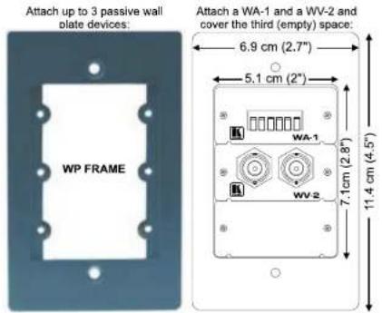
You can attach up to 3 of any of the 14 passive devices—7 wall plate devices (see section 4.1) and/or 7 connector module devices (see section 4.2)—to work with the WP Frame and/or the VPM-2 XGA Line Driver wall plate.
4.1 Passive Wall Plate Devices
Sections 5.1 and 5.2 respectively, describe how to attach up to 3 passivewall plate devices ^1 to the WP Frame or to the VPM-2 XGA Line Driver wall plate.
The 7 passive wall plate devices include the following:
• WA-3 (refer to section 4.1.1 on page 3)
• WA-1 (refer to section 4.1.2 on page 3)
• WA-2 (refer to section 4.1.3 on page 4)
• WV-2 (refer to section 4.1.4 on page 4)
• WAS-1 (refer to section 4.1.5 on page 5)
• WAV-1 (refer to section 4.1.6 on page 5)
• WX-1 (refer to section 4.1.7 on page 6)
Table 1 defines the dimensions of a passive wall plate device:
Table 1: Passive Wall Plate Device Dimensions
| DIMENSIONS: 5.05 cm x 4.7 cm x 2.34 cm (1.99" x 1.85" x 0.92", W, D, H) | |
| SPACING BETWEEN MOUNTING HOLES: | 4.3 cm (1.69") (see Figure 1) |
| MOUNTING HOLE DIAMETER: 3.2 cm (1.26") | |
4.1.1 WA-3 Dual Mini Headphone to Terminal Block Adapter
The Kramer WA-3 is dual 3.5mm mini headphone connector to a 6-pole terminal block adapter for connecting dual audio stereo channels, as Figure 1 illustrates ^1 :
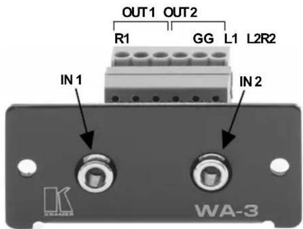
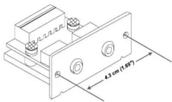
Figure 1: WA-3 Dual Mini Headphone to Terminal Block Adapter
4.1.2 WA-1 Terminal Blocks Adapter for Balanced Stereo Audio
The Kramer WA-1 is a 6-pole terminal block on both sides of the adapter for connecting balanced stereo audio, as Figure 2 illustrates:
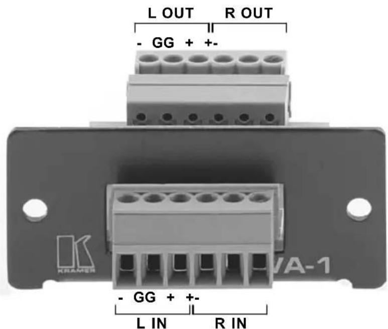
Figure 2: WA-1 Terminal Blocks Adapter for Balanced Stereo Audio
4.1.3 WA-2 Dual RCA to Terminal Block Adapter
The Kramer WA-2 is a dual RCA to 6-pole terminal block adapter for connecting a stereo audio signal (single stereo channel), as Figure 3 illustrates:
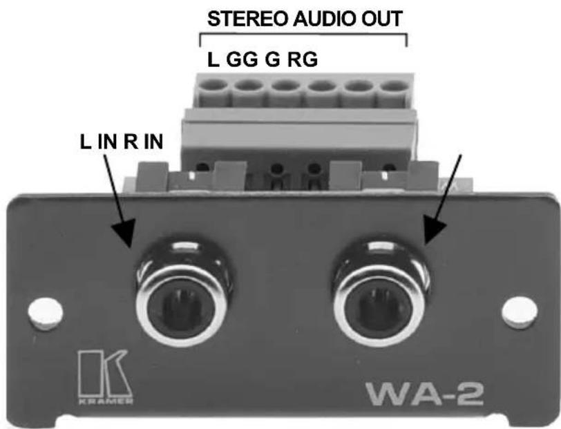
Figure 3: WA-2 Dual RCA to Terminal Block Adapter
4.1.4 WV-2 Dual BNC to Terminal Block Adapter
The Kramer WV-2 is a dual BNC to 6-pole terminal block adapter for connecting two video sources, as Figure 4 illustrates:
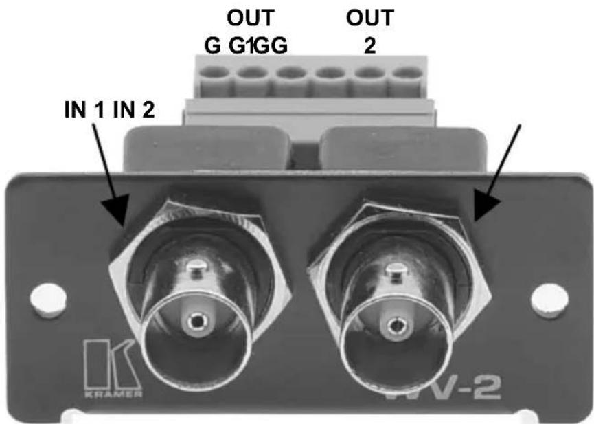
Figure 4: WV-2 Dual BNC to Terminal Block Adapter
4.1.5 = WAS-1 Mini Headphone + 4p Connectors to Terminal Block Adapter
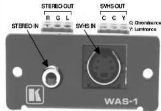
The Kramer WAS-1 is a 3.5 mini headphone connector and an s-Video 4 pin connector to 6-pole terminal block for connecting s-Video and stereo audio, as Figure 5 illustrates:
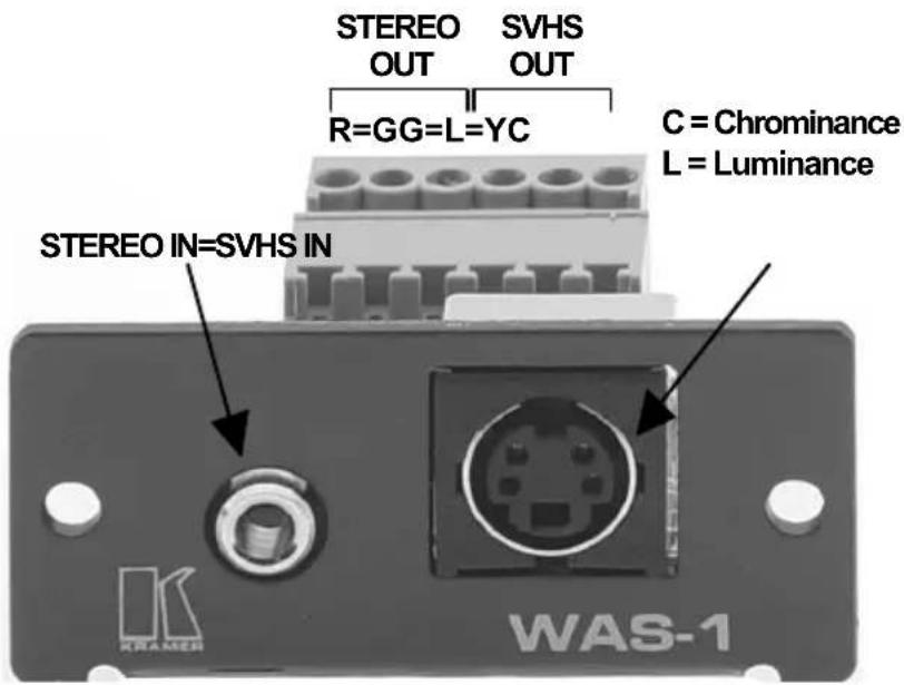
Figure 5: WAS-1 Mini Headphone + 4p Connectors to Terminal Block Adapter
4.1.6 = WAV-1 Mini Headphone + BNC Connectors to Terminal Block Adapter
The Kramer WAV-1 is a 3.5 mm mini headphone and BNC connector to a 6-pole terminal block for connecting video and stereo audio, as Figure 6 illustrates:
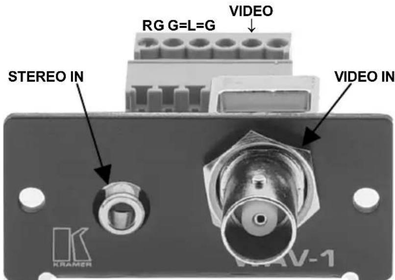
Figure 6: WAV-1 Mini Headphone + BNC Connectors to Terminal Block Adapter
4.1.7 =WX-1 HD15F to 6 + 2 Terminal Block Adapter
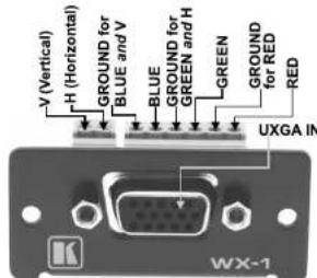
The Kramer WX-1 is an HD15F computer (VGA/SVGA/XGA/UXGA) video signal connector to 6 + 2 terminal block connector for connecting a graphics source with an ID Bit Control Switch ^1 , as Figure 7 illustrates:
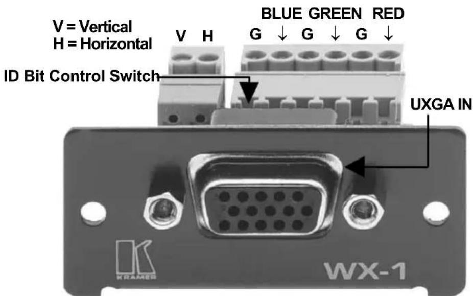
Figure 7: WX-1 HD15F to 6 +2 Terminal Block Adapter
4.2 = Passive Connector Module Devices
The 7 passive connector module devices are also designed to work with the WP Frame and/or the VPM-2 XGA Line Driver wall plate, as well as the 7 passive wall plate devices (described in section 4.1).
You can attach up to 3 of any 7 passive connector modules in the WP Frame or in the VPM-2 XGA Line Driver wall plate, as sections 5.1 and 5.2 describe respectively.
The 7 passive connector modules include the following:
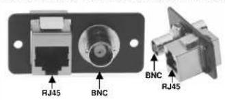
• WB45 (an RJ45/BNC connector module, as Figure 8 illustrates)
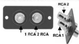
• WRR (a double RCA connector module, as Figure 9 illustrates)
• W1145 (an RJ11/RJ45 connector module)
• W4545 (a double RJ45 connector module)
• WBB (a double BNC connector module)
• WBR (a BNC/RCA connector module)
• WR45 (a RJ45/RCA connector module)
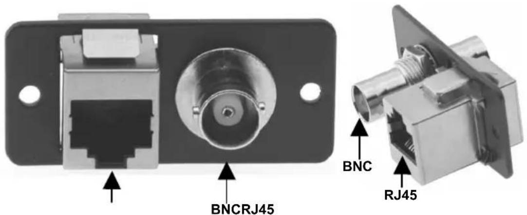
Figure 8: WB45 Passive RJ45/BNC Connector Module
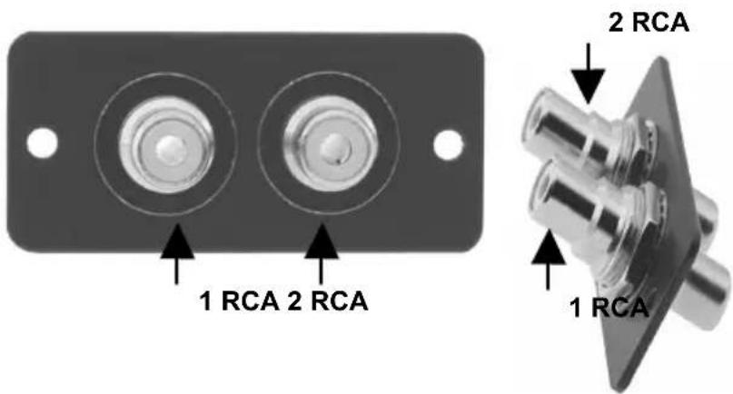
Figure 9: WRR Double RCA Connector Module Device
5 Wall Plate Receptacles
You can attach up to 3 passive wall plates or connector modules in the WP Frame or in the VPM-2 XGA Line Driver wall plate, as sections 5.1 and 5.2 describe respectively.
5.1 WP Frame
Figure 10 shows how to attach up to 3 passive wall plate devices or connector modules to the WP FRAME. If attaching just 1 or 2 passive wall plate devices, cover the empty space(s) with the removable panels that are included with the WP FRAME.
Wall Plate Receptacles
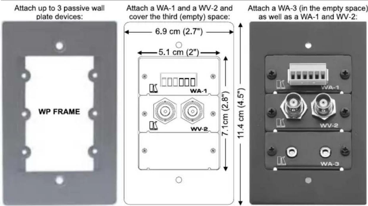
Figure 10: Attaching up to 3 Passive Wall Plate Devices in a WP Frame
5.2 VPM-2 XGA Line Driver Wall Plate
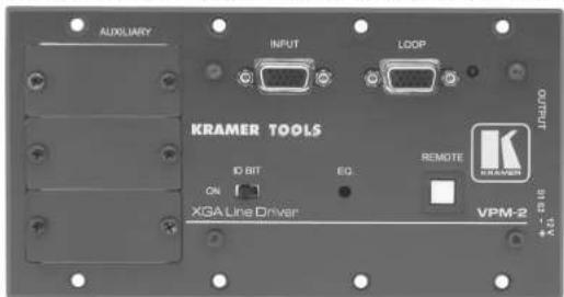
The VPM-2 wall plate has 3 removable panels designed into the product that can be replaced with up to 3 of the 14 passive devices —7 wall plate devices and/or 7 connector module devices, for example, the WA-1, WV-2 and WA-3, as Figure 11 illustrates.
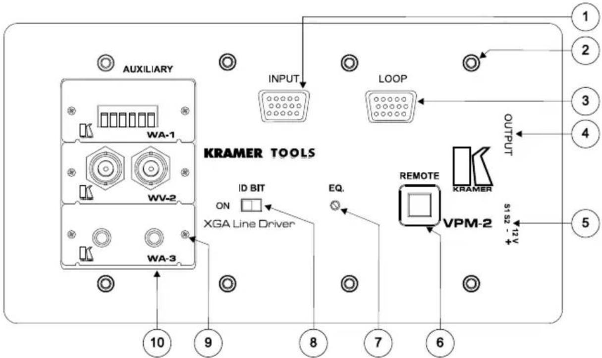
Figure 11: Attaching up to 3 Passive Devices in a VPM-2 XGA Line Driver Wall Plate
Table 2: VPM-2 XGA Line Driver Features and Functions
| # | Feature Function | |
| 1 | INPUT VGA/XGA input | |
| 2 | Mounting Screws (8) For fastening the VPM-2 in place | |
| 3 | LOOP For VGA/XGA looping to increase output availability | |
| 4 | OUTPUT VGA/XGA output | |
| 5 | 12V DC +12V DC connector for powering the unit | |
| 6 | REMOTE Button for activating a remote switcher | |
| 7 | CABLE EQ ^1 Potentiometer for adjusting cable equalization | |
| 8 | ID BIT Switch Selects ID BIT when switched ON in the left position (when outputting a VGA signal from a notebook to an external VGA monitor ^2 ) | |
| 9 | Mounting Screws(2 per passive device) | For fastening each passive device to theVPM-2 |
| 10 | 3 Removable Panels | Can be replaced with up to 3 passive (wall plate or connector module) devices |
The VPM-2 wall plate is available in 2 sizes, one for the US market and one for the European market, as Table 3 defines.
Table 3: VPM-2 XGA Line Driver Wall Plate Dimensions
| VPM-2 (US): 21.1 | cm x 11.4 cm (8.31" x 4.49", W, D) |
| VPM-2 (Europe): 18.2 cm x 9.55 cm (7.17" x 3.76", W, D) | |
6 Active Devices
The 7 active wall plate devices which accompany the VPM-2 as standalone products, include the following:
• WA-21 (refer to section 6.1 on page 9)
• WA-23 (refer to section 6.2 on page 11)
• WA-20 (refer to section 6.3 on page 12)
• WA-22 (refer to section 6.4 on page 13)
• WV-11 (refer to section 6.5 on page 14)
• WV-12 (refer to section 6.6 on page 15)
• WV-20 (refer to section 6.7 on page 16)
Table 4 defines the dimensions of an active wall plate device:
Table 4: Active Wall Plate Device Dimensions
| 6.9 cm x 5.0 cm x 11.4 cm (2.72" x 1.97" x 4.49", W, D, H) |
Table 5 defines the terminal block PINOUT ^3 on each active wall plate device.
Table 5: Active Wall Plate Device Terminal Block PINOUT
| WA-21; WA-23 WA-20; WA-22 WV-11 | WV-12 WV-20 | |||
| LINE OUTPUTS+ G - + G -R L | LINE INPUTS+ G - + G -R L | LINE OUTPUT+ G - | LINE INPUT+ G - | VIDEO OUTPUTS1 G 2 G |
6.1 WA-21 Audio TP Transmitter
The Kramer WA-21 is a 3.5 mm mini headphone connector to 6-pole terminal block for converting an unbalanced stereo audio signal to balanced audio (or act as a twisted-pair audio transmitter) with left and right audio level controls, as Figure 12 illustrates ^1 :
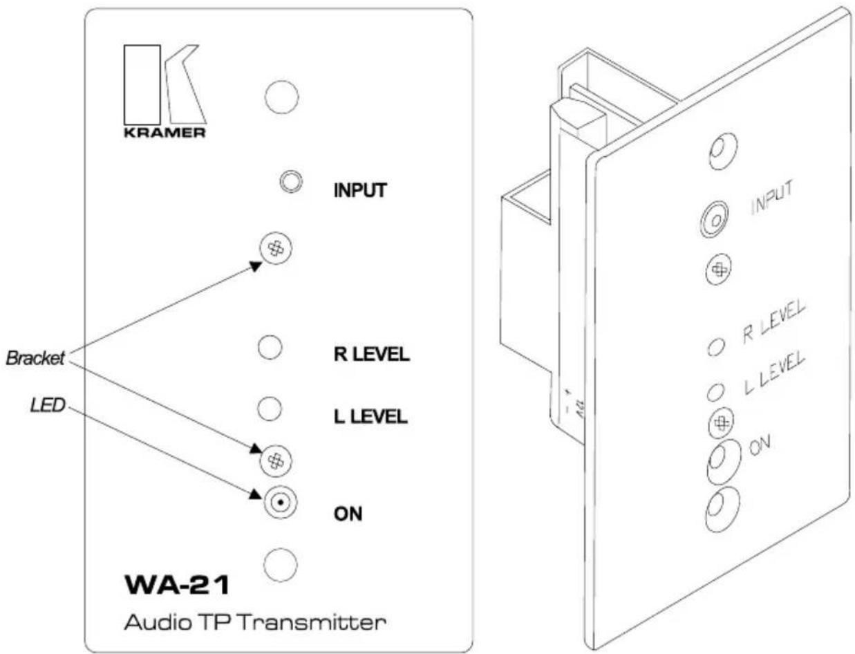
Figure 12: WA-21 Audio TP Transmitter
6.2 WA-23 Audio TP Transmitter
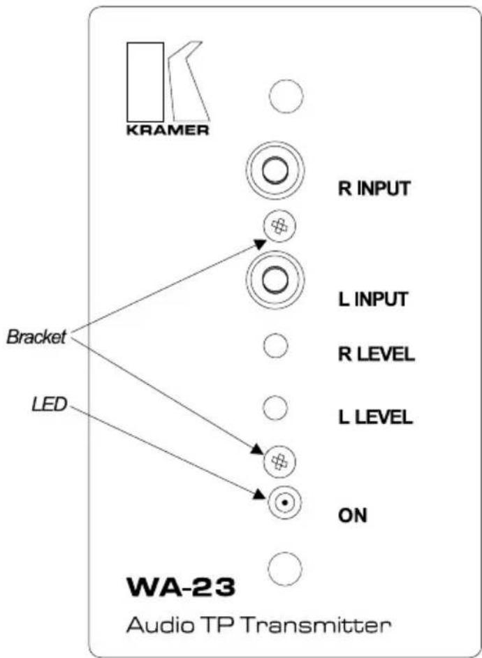
The Kramer WA-23 is a dual RCA connector to a 6-pole terminal block for converting an unbalanced stereo audio signal to balanced audio (or act as a twisted-pair audio transmitter) with left and right audio level controls, as Figure 13 illustrates:
flowchart
graph TD
    A["KRAMER"] --> B["Bracket"]
    C["LED"] --> D["ON"]
    E["R INPUT"] --> F["L INPUT"]
    G["R LEVEL"] --> H["L LEVEL"]
    I["○"] --> J["○"]
    K["○"] --> L["○"]
    M["○"] --> N["○"]
    O["○"] --> P["○"]
    Q["○"] --> R["○"]
    S["○"] --> T["○"]
    U["○"] --> V["○"]
    W["○"] --> X["○"]
    Y["○"] --> Z["○"]
    AA["○"] --> AB["○"]
    AC["○"] --> AD["○"]
    AE["○"] --> AF["○"]
    AG["○"] --> AH["○"]
    AI["○"] --> AJ["○"]
    AK["○"] --> AL["○"]
    AM["○"] --> AN["○"]
    AO["○"] --> AP["○"]
    AQ["○"] --> AR["○"]
    AS["○"] --> AT["○"]
    AU["○"] --> AV["○"]
    AW["○"] --> AX["○"]
Figure 13: WA-23 Audio TP Transmitter
6.3 WA-20 Audio TP Receiver
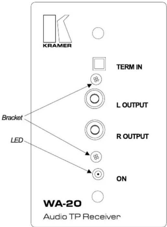
The Kramer WA-20 is a dual RCA connector output to a 6 -pole terminal block for converting balanced stereo audio to unbalanced stereo audio (or to act as a twisted pair stereo audio receiver), as Figure 14 illustrates:
flowchart
graph TD
    A["LED"] --> B["Bracket"]
    C["KRAMER"] --> D["TERM IN"]
    D --> E["L OUTPUT"]
    D --> F["R OUTPUT"]
    D --> G["ON"]
    style A fill:#f9f,stroke:#333
    style B fill:#ccf,stroke:#333
    style C fill:#cfc,stroke:#333
    style D fill:#fcc,stroke:#333
    style E fill:#cff,stroke:#333
    style F fill:#ffc,stroke:#333
    style G fill:#cfc,stroke:#333
Figure 14: WA-20 Audio TP Receiver
6.4 WA-22 Audio TP Receiver
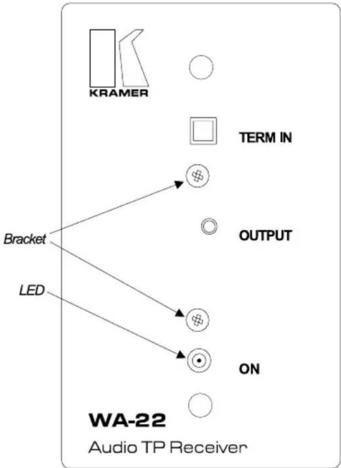
The Kramer WA-22 is a 3.5 mm mini headphone connector output to a 6-pole terminal block for converting balanced stereo audio to unbalanced stereo audio (or act as a twisted-pair stereo audio receiver), as Figure 15 illustrates:
flowchart
graph TD
    A["KRAMER"] --> B["Bracket"]
    C["LED"] --> D["ON"]
    E["TERM IN"] --> F["○"]
    G["OUTPUT"] --> H["○"]
    I["○"] --> J["○"]
    K["○"] --> L["○"]
    M["○"] --> N["○"]
    O["○"] --> P["○"]
    Q["○"] --> R["○"]
    S["○"] --> T["○"]
    U["○"] --> V["○"]
    W["○"] --> X["○"]
    Y["○"] --> Z["○"]
    AA["○"] --> AB["○"]
    AC["○"] --> AD["○"]
    AE["○"] --> AF["○"]
    AG["○"] --> AH["○"]
    AI["○"] --> AJ["○"]
    AK["○"] --> AL["○"]
    AM["○"] --> AN["○"]
    AO["○"] --> AP["○"]
    AQ["○"] --> AR["○"]
    AS["○"] --> AT["○"]
    AU["○"] --> AV["○"]
    AW["○"] --> AX["○"]
    AY["WA-22 Audio TP Receiver"]
Figure 15: WA-22 Audio TP Receiver
6.5 WV-11 Video TP Transmitter
The Kramer WV-11 has a BNC connector to a 3-pole terminal block twisted-pair transmitter with video level and EQ controls, enabling high quality video to be sent a distance of up to 1 km over twisted pair cable, as Figure 16 illustrates:
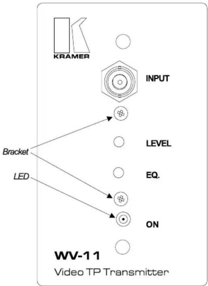
flowchart
graph TD
    A["KRAMER"] --> B["INPUT"]
    B --> C["⊕"]
    D["BRACKET"] --> E["LEVEL"]
    D --> F["EQ."]
    G["LED"] --> H["⊕"]
    I["ON"] --> J["⊕"]
    K["WV-11 Video TP Transmitter"]
Figure 16: WV-11 Video TP Transmitter
6.6 WV-12 Video TP Receiver
The Kramer WV-12 provides a video output (on a BNC connector) from a 3-pole terminal block to convert video over twisted-pair (balanced video) to single-ended (unbalanced) video. It provides video level and EQ controls and works in conjunction with the WV-11, as Figure 17 illustrates:
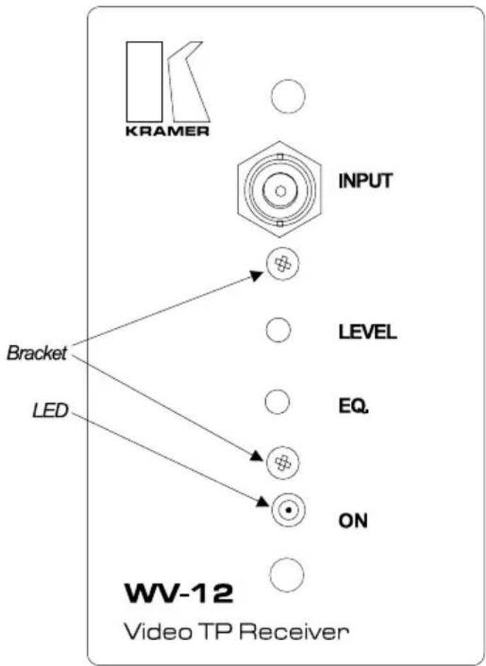
flowchart
graph TD
    A["KRAMER"] --> B["INPUT"]
    B --> C["LEVEL"]
    B --> D["EQ."]
    B --> E["ON"]
    F["BRACKET"] --> G["LED"]
    H["WV-12 Video TP Receiver"] --> I["○"]
Figure 17: WV-12 Video TP Receiver
6.7 WV-20 Video Line Amp / DA
The Kramer WV-20 is a 1:2 distribution amplifier and line driver for video on a BNC connector to a 3-pole terminal block connector. Video bandwidth exceeds 400 MHz and quality video can be obtained (when using high quality coax cables) even 300 meters (1000 ft) away. The WV-20 also provides video level and EQ controls, as Figure 18 illustrates:
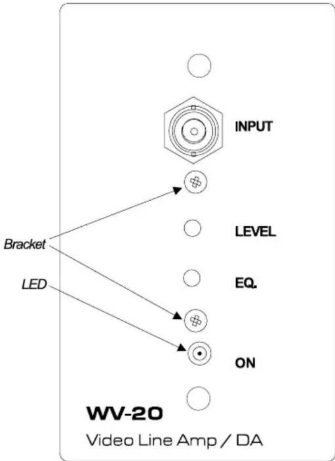
flowchart
graph TD
    A["INPUT"] --> B["⊕"]
    C["LEVEL"] --> D["○"]
    E["EQ."] --> F["○"]
    G["ON"] --> H["⊕"]
    I["LED"] --> J["○"]
    K["Bracket"] --> L["○"]
Figure 18: WV-20 Video Line Amp / DA
LIMITED WARRANTY
Kramer Electronics (hereafter Kramer) warrants this product free from defects in material and workmanship under the following terms.
HOW LONG IS THE WARRANTY
Labor and parts are warranted for three years from the date of the first customer purchase.
WHO IS PROTECTED?
Only the first purchase customer may enforce this warranty.
WHAT IS COVERED AND WHAT IS NOT COVERED
Except as below, this warranty covers all defects in material or workmanship in this product. The following are not covered by the warranty:
- Any product which is not distributed by Kramer, or which is not purchased from an authorized Kramer dealer. If you are uncertain as to whether a dealer is authorized, please contact Kramer at one of the agents listed in the web site www.kramerelectronics.com.
- Any product, on which the serial number has been defaced, modified or removed.
- Damage, deterioration or malfunction resulting from:
i) Accident, misuse, abuse, neglect, fire, water, lightning or other acts of nature
ii) Product modification, or failure to follow instructions supplied with the product
iii) Repair or attempted repair by anyone not authorized by Kramer
iv) Any shipment of the product (claims must be presented to the carrier)
v) Removal or installation of the product
vi) Any other cause, which does not relate to a product defect
vii) Cartons, equipment enclosures, cables or accessories used in conjunction with the product
WHAT WE WILL PAY FOR AND WHAT WE WILL NOT PAY FOR
We will pay labor and material expenses for covered items. We will not pay for the following:
- Removal or installations charges.
- Costs of initial technical adjustments (set-up), including adjustment of user controls or programming. These costs are the responsibility of the Kramer dealer from whom the product was purchased.
- Shipping charges.
HOW YOU CAN GET WARRANTY SERVICE
- To obtain service on you product, you must take or ship it prepaid to any authorized Kramer service center.
- Whenever warranty service is required, the original dated invoice (or a copy) must be presented as proof of warranty coverage, and should be included in any shipment of the product. Please also include in any mailing a contact name, company, address, and a description of the problem(s).
- For the name of the nearest Kramer authorized service center, consult your authorized dealer.
LIMITATION OF IMPLIED WARRANTIES
All implied warranties, including warranties of merchantability and fitness for a particular purpose, are limited in duration to the length of this warranty.
EXCLUSION OF DAMAGES
The liability of Kramer for any effective products is limited to the repair or replacement of the product at our option. Kramer shall not be liable for:
- Damage to other property caused by defects in this product, damages based upon inconvenience, loss of use of the product, loss of time, commercial loss; or:
- Any other damages, whether incidental, consequential or otherwise. Some countries may not allow limitations on how long an implied warranty lasts and/or do not allow the exclusion or limitation of incidental or consequential damages, so the above limitations and exclusions may not apply to you.
This warranty gives you specific legal rights, and you may also have other rights, which vary from place to place.
NOTE: All products returned to Kramer for service must have prior approval. This may be obtained from your dealer.
This equipment has been tested to determine compliance with the requirements of:
EN-50081: "Electromagnetic compatibility (EMC);
generic emission standard.
Part 1: Residential, commercial and light industry"
EN-50082: "Electromagnetic compatibility (EMC) generic immunity standard.
Part 1: Residential, commercial and light industry environment".
CFR-47: FCC Rules and Regulations:
Part 15: "Radio frequency devices
Subpart B – Unintentional radiators”
CAUTION!
Servicing the machines can only be done by an authorized Kramer technician. Any user who makes changes or modifications to the unit without the expressed approval of the manufacturer will void user authority to operate the equipment.
☒ Use the supplied DC power supply to feed power to the machine.
☒ Please use recommended interconnection cables to connect the machine to other components.
For the latest information on our products and a list of Kramer distributors, visit our Web site: www.kramerelectronics.com.
Updates to this user manual may be found at http://www.kramerelectronics.com/manuals.html. We welcome your questions, comments and feedback.
Kramer Electronics, Ltd.

natural_image
Abstract black geometric shape on white background (no text or symbols)KRAMER
USER MANUAL
Wall Plate (WP) Series
Passive Devices:
WXA-1, WVS-1, WVS-2, WAV-2, WXV-1
Active Devices:
WA-20N, WA-21N, WA-22N, WA-23N, WV-11N, WV-12N, WV-20N
Contents
1 Introduction 1
2 Getting Started 1
3 Overview 1
4 Passive Wall Plate (WP) Devices 2
4.1 WXA-1 2
4.2 WVS-1 3
4.3 WVS-2 4
4.4 WAV-2 5
4.5 WXV-1 6
5 Active Wall Plate (WP) Devices 7
5.1 WA-20N Twisted-Pair Audio Receiver 7
5.2 WA-21N Twisted-Pair Audio Transmitter 8
5.3 WA-22N Twisted-Pair Audio Receiver 9
5.4 WA-23N Twisted-Pair Audio Transmitter 10
5.5 WV-11N Video Twisted-Pair Transmitter 11
5.6 WV-12N Video Twisted-Pair Receiver 12
5.7 WV-20N Video Distribution Amplifier and Line Driver 13
Figures
Figure 1: WXA-1 2
Figure 2: WVS-1 3
Figure 3: WVS-2 4
Figure 4: WAV-2 5
Figure 5: WXV-1 6
Figure 6: WA-20N Twisted-Pair Audio Receiver 7
Figure 7: WA-21N Twisted-Pair Audio Transmitter 8
Figure 8: WA-22N Twisted-Pair Audio Receiver 9
Figure 9: WA-23N Twisted-Pair Audio Transmitter 10
Figure 10: WV-11N Video Twisted-Pair Transmitter 11
Figure 11: WV-12N Video Twisted-Pair Receiver 12
Figure 12: WV-20N Video Distribution Amplifier and Line Driver 13
Tables
Table 1: Dimensions of Wall Plates 1
1 Introduction
Welcome to Kramer Electronics (since 1981): a world of unique, creative and affordable solutions to the infinite range of problems that confront the video, audio and presentation professional on a daily basis. In recent years, we have redesigned and upgraded most of our line, making the best even better! Our 350-plus different models now appear in 8 Groups ^1 , which are clearly defined by function. Congratulations on purchasing your Kramer wall plate ^2 , which is ideal for the following applications: board, conference and training rooms, presentation systems, and long distance signal distribution and home theater.
2 Getting Started
We recommend that you:
- Unpack the equipment carefully and save the original box and packaging materials for possible future shipment
- Review the contents of this user manual
- Use Kramer high performance high resolution cables ^3
3 Overview
Table 1 defines the wall plate dimensions:
Table 1: Dimensions of Wall Plates
| Wall Plate Destined For Dimensions |
| Belgium and Germany 8.00cm x 4.08cm x 8.00cm (3.15" x 1.61" x 3.15", W, D, H) |
| England and Europe ^4 8.60cm x 4.08cm x 8.60cm (3.39" x 1.61" x 3.39", W, D, H) |
| United States 6.90cm x 4.08cm x 11.43cm (2.72" x 1.61" x 4.50", W, D, H) |
To achieve the best performance you should:
- Connect only good quality connection cables, thus avoiding interference, deterioration in signal quality, and elevated noise levels (often associated with low quality cables)
- Position your Kramer wall plate securely, and in a location that is free from moisture and away from excessive sunlight and dust
4 Passive Wall Plate (WP) Devices
Sections 4.1 to 4.5 describe the following passive wall plates:
• WXA-1 (refer to section 4.1)
• WVS-1 (refer to section 4.2)
• WVS-2 (refer to section 4.3)
• WAV-2 (refer to section 4.4)
• WXV-1 (refer to section 4.5)
4.1 WXA-1
The Kramer WXA-1 is an HD15F computer (VGA/SVGA/XGA/UXGA) video signal connector and a 3.5mm mini headphone audio connector to 6 + 6 terminal block connectors, as Figure 1 illustrates:
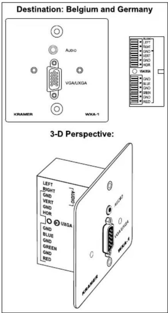
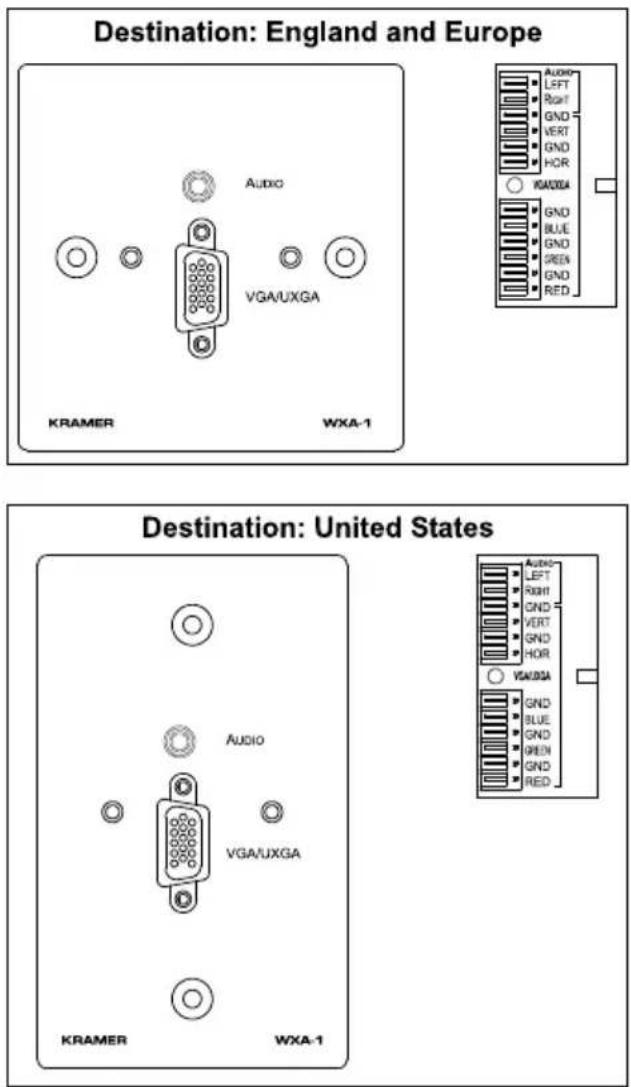
Figure 1: WXA-1
4.2 WVS-1
The Kramer WVS-1 is a dual RCA stereo audio and s-Video 4p connector to 3-pole + 6-pole terminal block connectors, as Figure 2 illustrates:
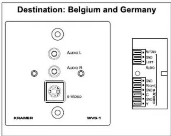
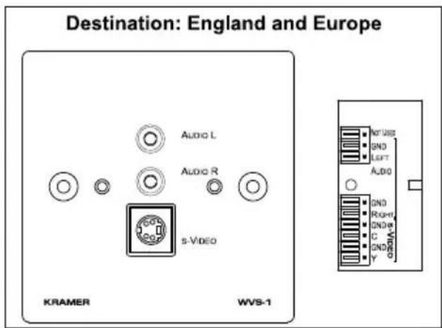
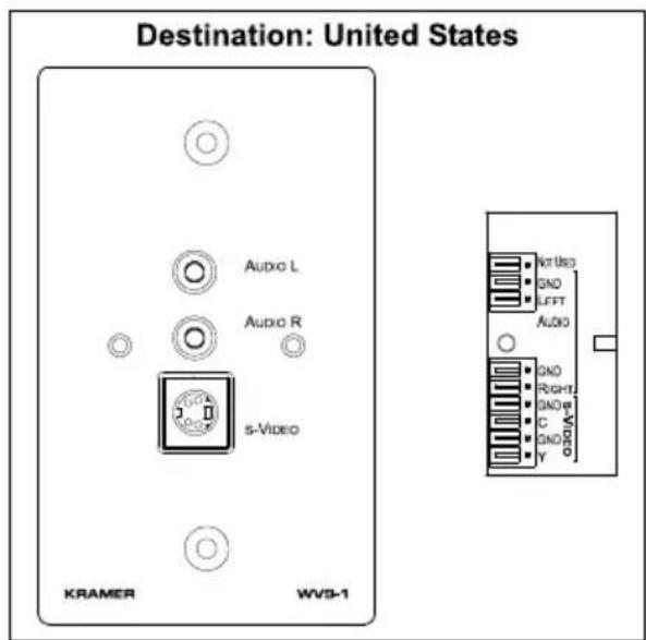
Figure 2: WVS-1
4.3 WVS-2
The Kramer WVS-2 is a dual 3.5mm mini headphone audio connector, composite video RCA connector and s-Video 4p connector to 6-pole + 6-pole terminal block connectors, as Figure 3 illustrates:
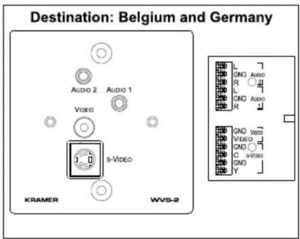
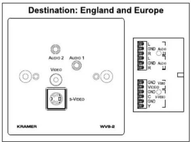
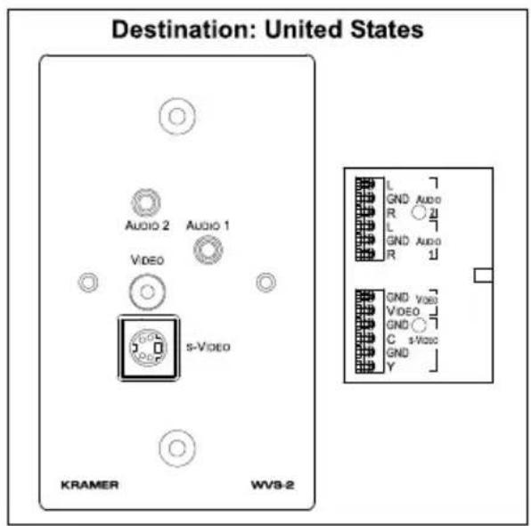
Figure 3: WVS-2
4.4 WAV-2
The Kramer WAV-2 is a 3.5mm mini headphone audio connector, 3 x composite video RCA connectors to 3-pole + 6-pole terminal block connectors, as Figure 4 illustrates:
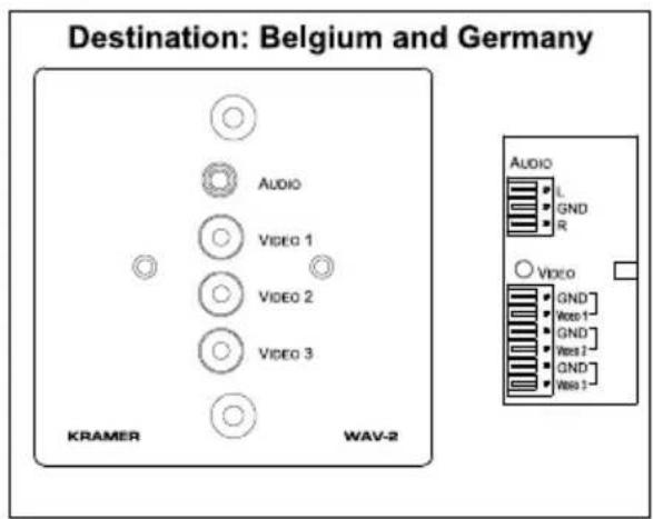
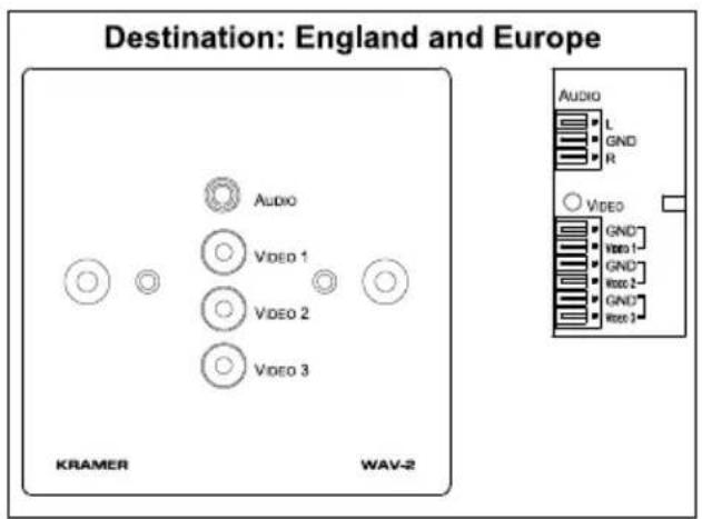
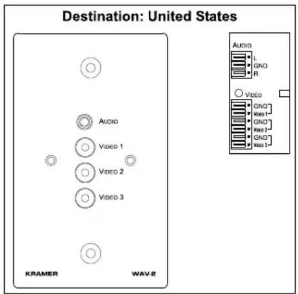
Figure 4: WAV-2
4.5 WXV-1
The Kramer WXV-1 is a composite video RCA connector and an HD15F computer (VGA/SVGA/XGA/UXGA) video signal connector to 6-pole + 6-pole terminal block connectors, as Figure 5 illustrates:
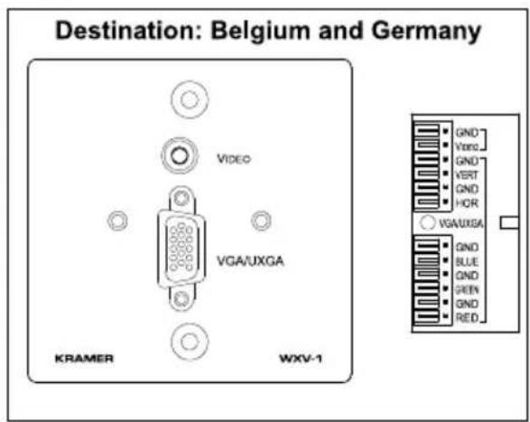
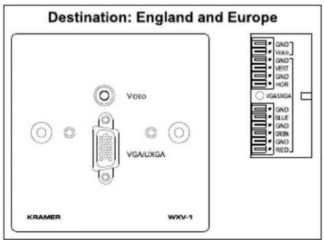
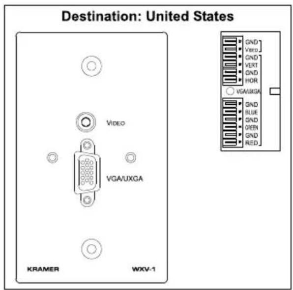
Figure 5: WXV-1
5 Active Wall Plate (WP) Devices
Sections 5.1 to 5.7 describe the following active wall plates:
• WA-20N (refer to section 5.1)
• WA-21N (refer to section 5.2)
• WA-22N (refer to section 5.3)
• WA-23N (refer to section 5.4)
• WV-11N (refer to section 5.5)
• WV-12N (refer to section 5.6)
• WV-20N (refer to section 5.7)
5.1 WA-20N Twisted-Pair Audio Receiver
The Kramer WA 20N—a twisted-pair audio receiver—is a dual RCA connector from 6-pole + 2-pole terminal blocks, as Figure 6 illustrates:
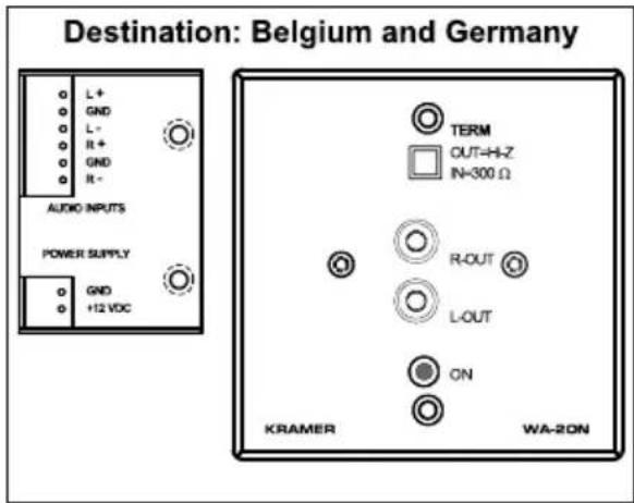
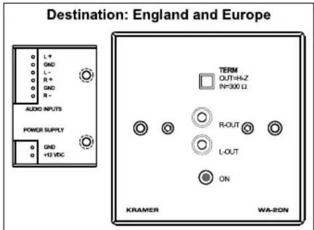
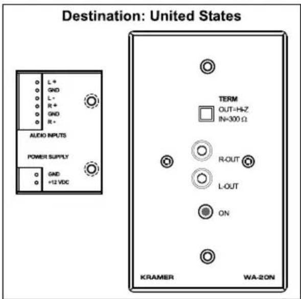
Figure 6: WA-20N Twisted-Pair Audio Receiver
5.2 WA-21N Twisted-Pair Audio Transmitter
The Kramer WA-21N—a twisted-pair audio transmitter—is a 3.5mm mini headphone audio connector to 6-pole + 2-pole terminal blocks, with left and right audio level controls, as Figure 7 illustrates:
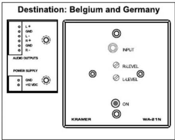
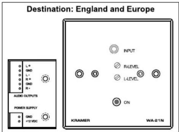
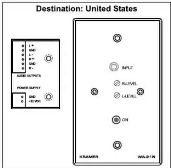
Figure 7: WA-21N Twisted-Pair Audio Transmitter
Table 2: WA-21N Twisted-Pair Audio Receiver Technical Specifications
| INPUT: 1 Audio stereo on | 3.5mm phone jack |
| OUTPUT: 1 CAT 5 different | ential stereo on 6-pin terminal block |
| BANDWIDTH (-3dB): >100kHz | |
| S/N RATIO: 80dB | |
| CONTROLS: Level: -30dB to 6dB | |
| COUPLING: AC | |
| AUDIO THD + NOISE: 0.05%@1kHz | |
| AUDIO 2nd HARMONIC: | 0.005%@1kHz |
| POWER SOURCE: 12V DC, 30mA | |
5.3 WA-22N Twisted-Pair Audio Receiver
The Kramer WA 22N—a twisted-pair audio receiver—is a 3.5mm mini headphone audio connector from 6-pole + 2-pole terminal blocks, with a termination switch, as Figure 8 illustrates:
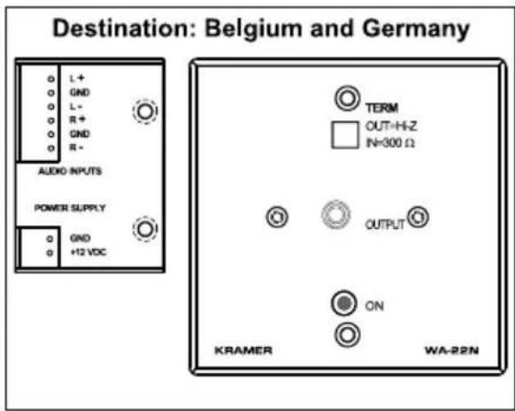
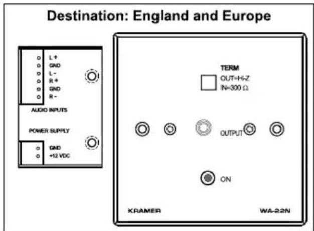
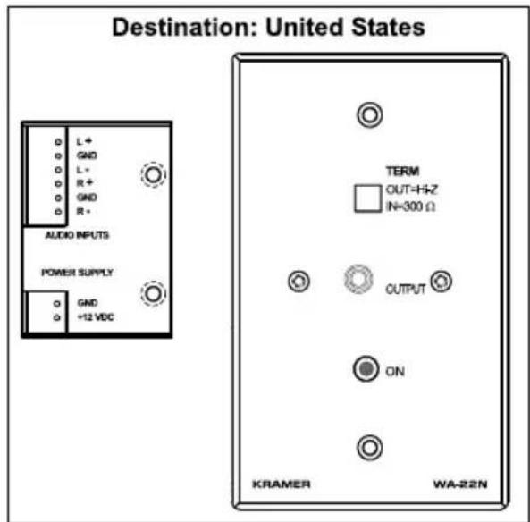
Figure 8: WA-22N Twisted-Pair Audio Receiver
Table 3: WA-22N Twisted-Pair Audio Receiver Technical Specifications
| INPUT: 1 RJ-45 CAT 5 | differential stereo on 6-pin terminal block |
| OUTPUT: 1 Audio stereo on 3.5mm phone jack | |
| MAX. OUTPUT LEVEL: | 5Vpp |
| BANDWIDTH (-3dB): >100kHz | |
| S/N RATIO: 80dB | |
| COUPLING: AC | |
| AUDIO THD + NOISE: | 0.05%@1kHz |
| AUDIO 2^nd HARMONIC: | 0.005%@1kHz |
| POWER SOURCE: 12V | DC, 30mA |
5.4 WA-23N Twisted-Pair Audio Transmitter
The Kramer WA-23N—a twisted-pair audio transmitter—is a dual RCA audio connectors to 6-pole + 2-pole terminal blocks with left and right audio level controls, as Figure 9 illustrates:
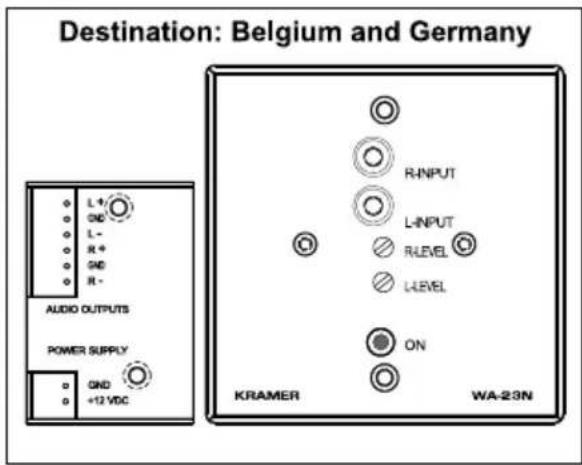
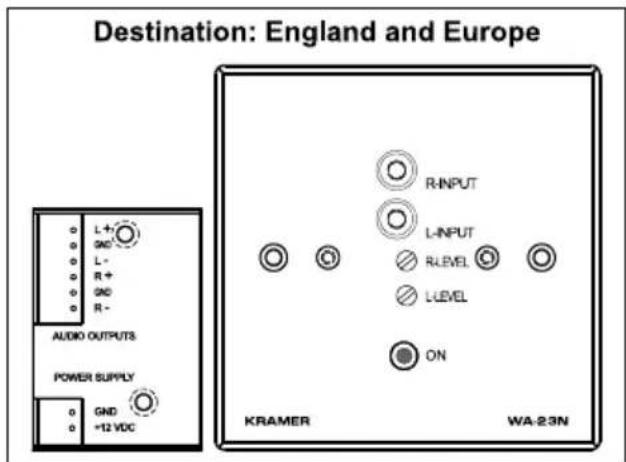
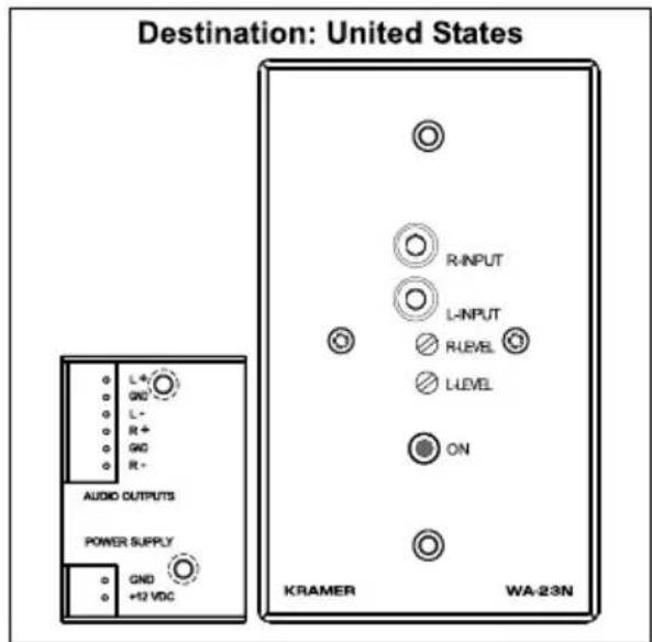
Figure 9: WA-23N Twisted-Pair Audio Transmitter
5.5 WV-11N Video Twisted-Pair Transmitter
The Kramer WV-11N—a video twisted-pair transmitter—is a composite video BNC input connector to 3-pole + 2-pole terminal blocks with video level and EQ. controls, as Figure 10 illustrates:
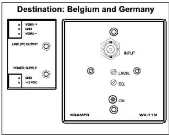
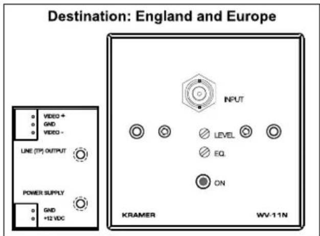
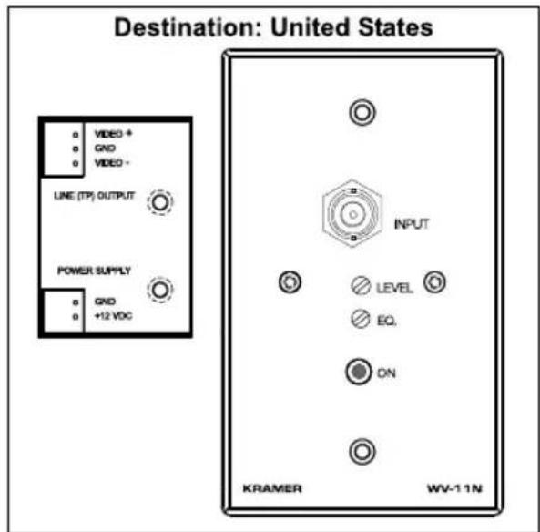
Figure 10: WV-11N Video Twisted-Pair Transmitter
5.6 WV-12N Video Twisted-Pair Receiver
The Kramer WV-12N—a video twisted-pair receiver—has a composite video BNC output connector from a 3-pole + 2-pole terminal blocks with video level and EQ. controls, as Figure 11 illustrates:
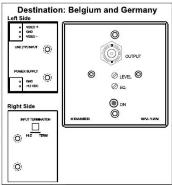
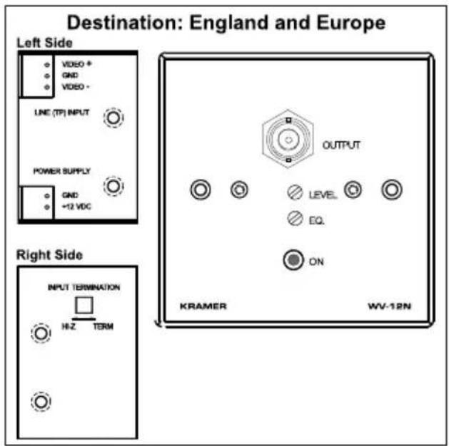
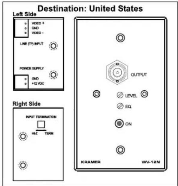
Figure 11: WV-12N Video Twisted-Pair Receiver
5.7 WV-20N Video Distribution Amplifier and Line Driver
The Kramer WV-20N is a 1:2 video distribution amplifier and line driver for composite video on a BNC input connector to a 3-pole + 2-pole terminal block connector, with video level and EQ. controls, as Figure 12 illustrates:
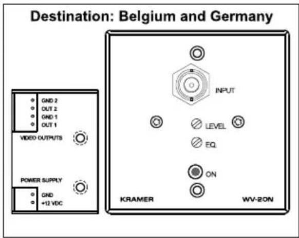
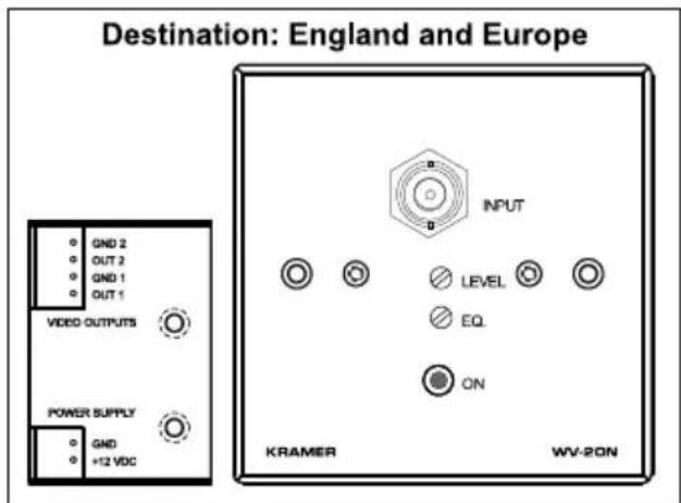
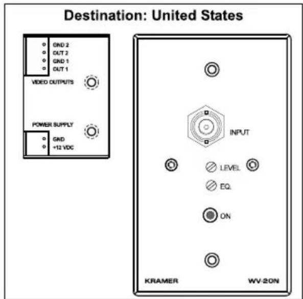
Figure 12: WV-20N Video Distribution Amplifier and Line Driver
LIMITED WARRANTY
Kramer Electronics (hereafter Kramer) warrants this product free from defects in material and workmanship under the following terms.
HOW LONG IS THE WARRANTY
Labor and parts are warranted for three years from the date of the first customer purchase.
WHO IS PROTECTED?
Only the first purchase customer may enforce this warranty.
WHAT IS COVERED AND WHAT IS NOT COVERED
Except as below, this warranty covers all defects in material or workmanship in this product. The following are not covered by the warranty:
- Any product which is not distributed by Kramer, or which is not purchased from an authorized Kramer dealer. If you are uncertain as to whether a dealer is authorized, please contact Kramer at one of the agents listed in the web site www.kramerelectronics.com.
- Any product, on which the serial number has been defaced, modified or removed.
- Damage, deterioration or malfunction resulting from:
i) Accident, misuse, abuse, neglect, fire, water, lightning or other acts of nature
ii) Product modification, or failure to follow instructions supplied with the product
iii) Repair or attempted repair by anyone not authorized by Kramer
iv) Any shipment of the product (claims must be presented to the carrier)
v) Removal or installation of the product
vi) Any other cause, which does not relate to a product defect
vii) Cartons, equipment enclosures, cables or accessories used in conjunction with the product
WHAT WE WILL PAY FOR AND WHAT WE WILL NOT PAY FOR
We will pay labor and material expenses for covered items. We will not pay for the following:
- Removal or installations charges.
- Costs of initial technical adjustments (set-up), including adjustment of user controls or programming. These costs are the responsibility of the Kramer dealer from whom the product was purchased.
- Shipping charges.
HOW YOU CAN GET WARRANTY SERVICE
- To obtain service on you product, you must take or ship it prepaid to any authorized Kramer service center.
- Whenever warranty service is required, the original dated invoice (or a copy) must be presented as proof of warranty coverage, and should be included in any shipment of the product. Please also include in any mailing a contact name, company, address, and a description of the problem(s).
- For the name of the nearest Kramer authorized service center, consult your authorized dealer.
LIMITATION OF IMPLIED WARRANTIES
All implied warranties, including warranties of merchantability and fitness for a particular purpose, are limited in duration to the length of this warranty.
EXCLUSION OF DAMAGES
The liability of Kramer for any effective products is limited to the repair or replacement of the product at our option. Kramer shall not be liable for:
- Damage to other property caused by defects in this product, damages based upon inconvenience, loss of use of the product, loss of time, commercial loss; or:
- Any other damages, whether incidental, consequential or otherwise. Some countries may not allow limitations on how long an implied warranty lasts and/or do not allow the exclusion or limitation of incidental or consequential damages, so the above limitations and exclusions may not apply to you.
This warranty gives you specific legal rights, and you may also have other rights, which vary from place to place.
NOTE: All products returned to Kramer for service must have prior approval. This may be obtained from your dealer.
This equipment has been tested to determine compliance with the requirements of:
EN-50081: "Electromagnetic compatibility (EMC);
generic emission standard.
Part 1: Residential, commercial and light industry"
EN-50082: "Electromagnetic compatibility (EMC) generic immunity standard.
Part 1: Residential, commercial and light industry environment".
CFR-47: FCC Rules and Regulations:
Part 15: "Radio frequency devices
Subpart B – Unintentional radiators”
CAUTION!
Servicing the machines can only be done by an authorized Kramer technician. Any user who makes changes or modifications to the unit without the expressed approval of the manufacturer will void user authority to operate the equipment.
☒ Use the supplied DC power supply to feed power to the machine.
☒ Please use recommended interconnection cables to connect the machine to other components.
For the latest information on our products and a list of Kramer distributors, visit our Web site: www.kramerelectronics.com.
Updates to this user manual may be found at http://www.kramerelectronics.com/manuals.html. We welcome your questions, comments and feedback.

CE
Passive WP Series (Wall Plate Devices and Connection Modules)
Congratulations on purchasing your Kramer WP Series (passive wall plate device and/or passive connection module), which is ideal for the following applications:
• Board, conference and training rooms
- Presentation systems
• Home theater
You can attach up to 3 of any of the devices from the passive WP Series—wall plate devices and/or connector module devices—to work with the WP Frame, and/or the VPM-2 XGA Line Driver wall plate. You can also include wall plate/connector module devices in the TBUS-1.
Wall Plate Devices (WA-3, WA-1, WA-2, WV-2, WAS-1, WAV-1, WX-1)
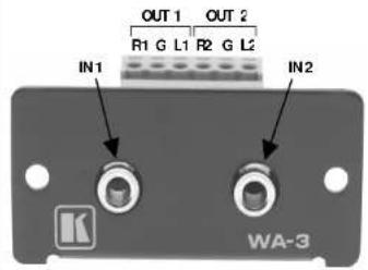
The WA-3 is a dual 3.5mm mini headphone connector to a 6-pole terminal block adapter for connecting dual audio stereo channels:
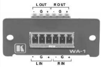
The WA-1 is a 6-pole terminal block on both sides of the adapter for connecting balanced stereo audio:
3-D view of the WA-3, which is similar for each passive wall plate device:
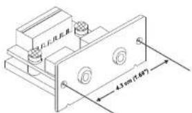
DIMENSIONS: 5.05cm x 4.7cm x 2.34cm (1.99" x 1.85" x 0.92", W, D, H) SPACING BETWEEN MOUNTING HOLES: 4.3cm (1.69")
The WA-2 is a dual RCA to 4-pole terminal block adapter for connecting a stereo audio signal (single stereo channel):
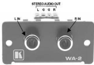
The WV-2 is a dual BNC to two 3-pole terminal block adapter for connecting two video sources:
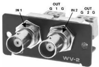
The WAV-1 is a 3.5mm mini headphone and BNC connector to two 3-pole terminal blocks for connecting video and stereo audio:
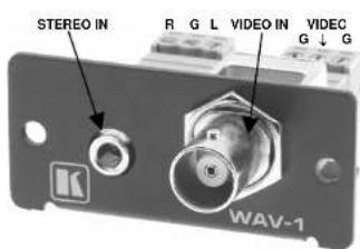
The WAS-1 is a 3.5 mini headphone connector and an s-Video 4 pin connector to two 3-pole terminal blocks for connecting s-Video and stereo audio:
The WX-1 is an HD15F computer (VGA/SVGA/XGA/UXGA) video signal connector to 6 + 2 terminal block connector for connecting a graphics source. The device includes an ID Bit Control Switch:
Connector Module Devices (WB45, WRR, W1145, W4545, WBB, WBR, WR45)
The WB45 is an RJ45/BNC connector module
The WRR is a double RCA connector module:
Other connector module devices include the W1145 (an RJ11/RJ45 connector module), the W4545 (a double RJ45 connector module), the WBB (a double BNC connector module), the WBR (a BNC/RCA connector module), and the WR45 (an RJ45/RCA connector module).
WP Frame (a 3 Slot frame is available in the U.S.; 2 and 4 Slot frames are available in Europe)
You can attach up to 3 of any of the passive devices. If attaching just 1 or 2 passive devices, cover the empty space(s) with the removable panels that are included with the WP FRAME.
Six Frame Adapter for 19" 1U Rack
You can attach up to 6 of any of the passive devices to the 19" 1U Rack Adapter

natural_image
Pure electrical circuit lines without any symbolsVPM-2 XGA Line Driver Wall Plate
The VPM-2 wall plate has 3 removable panels designed into the product that can be replaced with up to 3 passive devices. It is available in 2 sizes, one for the US market (21.1cm x 11.4cm (8.31" x 4.49", W, D)) and one for the European market (18.2cm x 9.55cm (7.17" x 3.76", W, D)).

Wall Plate (WP) Series
Passive Wall Plate Devices:
WA-1, WA-2, WA-3, WV-2, WAS-1, WAV-1, WX-1
Passive Connection Modules:
WB45, WRR, W1145, W4545, WBB, WBR, WR45
For the latest information on our products and a list of Kramer distributors, visit our Web site: www.kramerelectronics.com

CE
Kramer Electronics, Ltd.
Web site: www.kramerelectronics.com
E-mail: info@kramerel.com
P/N: 2900-006019 REV 7
- Kramer Electronics, Ltd.
- USER MANUAL
- Contents
- Figures
- Tables
- Introduction
- Getting Started
- Wall Plate (WP) Series
- Passive Devices
- Passive Wall Plate Devices
- WA-3 Dual Mini Headphone to Terminal Block Adapter
- WA-1 Terminal Blocks Adapter for Balanced Stereo Audio
- WA-2 Dual RCA to Terminal Block Adapter
- WV-2 Dual BNC to Terminal Block Adapter
- = WAS-1 Mini Headphone + 4p Connectors to Terminal Block Adapter
- = WAV-1 Mini Headphone + BNC Connectors to Terminal Block Adapter
- =WX-1 HD15F to 6 + 2 Terminal Block Adapter
- = Passive Connector Module Devices
- Wall Plate Receptacles
- WP Frame
- VPM-2 XGA Line Driver Wall Plate
- Active Devices
- WA-21 Audio TP Transmitter
- WA-23 Audio TP Transmitter
- WA-20 Audio TP Receiver
- WA-22 Audio TP Receiver
- WV-11 Video TP Transmitter
- WV-12 Video TP Receiver
- WV-20 Video Line Amp / DA
- LIMITED WARRANTY
- HOW LONG IS THE WARRANTY
- WHO IS PROTECTED?
- WHAT IS COVERED AND WHAT IS NOT COVERED
- WHAT WE WILL PAY FOR AND WHAT WE WILL NOT PAY FOR
- HOW YOU CAN GET WARRANTY SERVICE
- LIMITATION OF IMPLIED WARRANTIES
- EXCLUSION OF DAMAGES
- CAUTION!
- Overview
- Passive Wall Plate (WP) Devices
- WXA-1
- WVS-1
- WVS-2
- WAV-2
- WXV-1
- Active Wall Plate (WP) Devices
- WA-20N Twisted-Pair Audio Receiver
- WA-21N Twisted-Pair Audio Transmitter
- WA-22N Twisted-Pair Audio Receiver
- WA-23N Twisted-Pair Audio Transmitter
- WV-11N Video Twisted-Pair Transmitter
- WV-12N Video Twisted-Pair Receiver
- WV-20N Video Distribution Amplifier and Line Driver
- Passive WP Series (Wall Plate Devices and Connection Modules)
- Wall Plate Devices (WA-3, WA-1, WA-2, WV-2, WAS-1, WAV-1, WX-1)
- Connector Module Devices (WB45, WRR, W1145, W4545, WBB, WBR, WR45)
- Wall Plate (WP) Series
Brand : Kramer
Model : FRAME-1G
Category : Wall socket