
36-2914 - Security Camera Clas Ohlson - Free user manual and instructions
Find the device manual for free 36-2914 Clas Ohlson in PDF.


| Product Type | Security Camera |
| Brand | Clas Ohlson |
| Model | 36-2914 |
| Dimensions (H x W x D) | 110 mm x 70 mm x 70 mm |
| Weight | 0.3 kg |
| Power Supply | DC 12V, 1A |
| Video Resolution | 1920 x 1080 (Full HD) |
| Night Vision | Infrared LEDs, up to 10 m |
| Motion Detection | Yes, with adjustable sensitivity |
| Viewing Angle | 90° diagonal |
| Connectivity | Wired (BNC, RCA) |
| Storage | Supports DVR recording (not included) |
| Weather Resistance | IP66 (outdoor use) |
| Mounting Type | Wall or ceiling mount bracket included |
| Operating Temperature | -20°C to 50°C |
| Maintenance | Clean lens with soft dry cloth; avoid water |
| Safety | For indoor/outdoor use; keep away from heat sources |
| Spare Parts | Power adapter and mounting kit available |
| Repairability | Non-user-serviceable; contact support |
| General Information | Includes 1-year warranty |
Frequently Asked Questions - 36-2914 Clas Ohlson
User questions about 36-2914 Clas Ohlson
0 question about this device. Answer the ones you know or ask your own.
Ask a new question about this device
Download the instructions for your Security Camera in PDF format for free! Find your manual 36-2914 - Clas Ohlson and take your electronic device back in hand. On this page are published all the documents necessary for the use of your device. 36-2914 by Clas Ohlson.
USER MANUAL 36-2914 Clas Ohlson
natural_image
White industrial water heater with circular glass lid and base (no visible text or symbols)Article number 36-2914 Model RC8030 18-2062 RC8030-UK
Wireless IP Camera
Article number 36-2914 Model RC8030
18-2062 RC8030-UK
Please read the entire instruction manual before using the product and save it for future reference. We apologise for any text or photographic errors and any changes of technical data. If you have any questions concerning technical problems please contact our Customer Service Department (see address on reverse).
Table of Contents
- Safety 3
- Product Description 4
- Features 5
- Mounting and installation 6
- Basic Setup 7
- Show the camera image via the web browser 11
- Configuration via the web browser 12
- Advanced use 27
- Monitor Manager 30
- Care and Maintenance 40
- Troubleshooting 40
- Disposal 40
- Specifications 40
1. Safety
• The camera is for indoor use only.
• Use only the supplied or recommended power adaptor (5 V DC).
- Never expose the camera to moisture or humidity.
• Always disconnect the camera from the electricity network before cleaning.
- Never dismantle the camera. Certain parts inside the casing carry dangerous currents. Touching these can give you an electric shock.
2. Product Description
2.1 Features
Wireless IP camera with motor with the possibility to control the camera from another computer.
- 126irc (horizontal) + 64irc (vertical) panorama angle.
• CMOS Picture sensor. - The MPEG 4 technology offers high video quality but reduced band width directly to pc.
- Built-in microphone and connector for speakers for two-way communication between computer and camera.
• Software programme for configuration, monitoring, and recording. - Configuration via installation guide.
• Alarm and recording during motion detection.
• Scheduled recording.
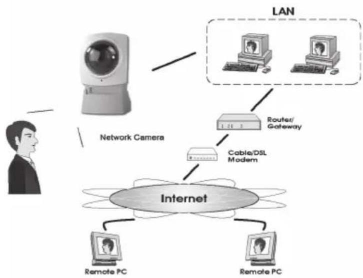
flowchart
graph TD
    A["Internet"] --> B["Network Camera"]
    B --> C["LAN"]
    C --> D["Router/Gateway"]
    D --> E["Cable/DSL Modem"]
    E --> F["Remote PC"]
    E --> G["Remote PC"]
Internet functions
- Definable http-port Allows the user to pick a port for access via the Internet.
- Support for DDNS (Dynamic DNS) Function for updates against a Dynamic DNS-server.
- NTP (Network Time Protocol) Synchronization of the clock against an Internet time server.
Safety Features
- User verification The camera can be password protected for up to 20 users.
- Password protected configuration Prevents unauthorized change of the camera's properties.
2.2 System requirements
• Network connected PC with Windows 2000 or XP
• Microsoft Internet Explorer 6.0 or later
- Router/Wireless access point
2.3 The package contains
• Network camera with aerial
• Power adaptor (5 V DC)
- Installation disc
- Instruction manual
3. Features
3.1 Front of camera
| Camera lens The | camera lens can be adjusted. However make sure that it is free from dirt and dust to obtain the best image. |
| Microphone | The built-in microphone is located on the front of the camera. There is also a socket on the back of the camera for an extra microphone. When an external microphone is connected the internal microphone is disconnected. |
| POWER LEDs illuminate when the camera is turned on.When the camera starts the LEDs flash for 15-20 seconds. | |
| ACTIVE When the LEDs flash, the camera image is transferred in real time to one or several users. | |
| NETWORK LEDs are lit when the camera is connected to a network.The LEDs flash when data is transmitted on the network. | |
3.2 Back of camera
| Power input Connection for the supplied power adaptor. | |
| MIC In Connection | (3.5 mm) for external microphone (e.g. a regular pc microphone).The camera's built-in microphone is automatically disconnected when an external microphone is connected. |
| LAN Use a standard network cable to connect the camera to your network switch or router.N.B.When a network cable is connected the wireless network (WLAN) is automatically disconnected.The power adaptor must always be disconnected before you connect or disconnect the network cable for the camera to be able to change between LAN or WLAN. | |
| RESET The reset button has two functions:A quick press restores the camera to a DHCP client (the camera obtains an IP address from e.g. a router. Any personal configured IP address is removed).A long press (press and hold in for 3 seconds) restores the IP address, administrator's name and the administrator's password. The LED (Power) blinks three times when the camera is restored.IP address: DHCPAdministrator's name: administratorAdministrator's password: (no password) | |
| SPEAK | Connection for speakers (3,5 mm). |
4. Mounting & Installation
1. Mounting the aerial
Attach the supplied aerial to the bracket on top of the camera. The aerial can be angled for the best possible reception. The best reception is obtained with the aerial angled vertically.
2. Mounting the camera
Mount the camera on the included table stand. The table stand can also be ceiling or wall mounted.
3. Connecting the network cable
Use a standard network cable for the LAN connection to connect the camera to your network switch or router.
N.B. You must first connect the camera with the network lead in order to configure the camera for the wireless network. You can remove the network lead after configuration.
4. Switching on the camera
Connect the supplied power adaptor to the outlet marked POWER. The camera starts up automatically. Use only the included or recommended adaptor.
5. LED Indicators
- POWER - At start-up the indicator is lit for a short while before it begins flashing for 15-20 seconds. The indicator then remains lit.
- ACTIVE - Lights only when video is transmitted in real time to one or several users.
- NETWORK - Lights when the camera is connected to the network.
5. Basic Setup
5.1 Configuring the camera
The camera must first be configured before using.
These installation instructions apply to Windows XP with Service pack 2 installed.
- Connect the camera according to the instructions in section 4.
-
Insert the supplied CD into the computer's CD-ROM drive. If the installation does not start automatically, use the file NetworkCamera.exe application found directly under the root folder on the CD-ROM.
-
When the installation programme has started a welcome screen is displayed. Click on Setup Camera to start the installation.

- The installation programme searches for the camera on the network and then displays the camera on the list to the left.

- On the next screen you will be prompted to enter a user name and password. Then click ▶.
The preset username and password are:
User name: administrator
Password: (no password)
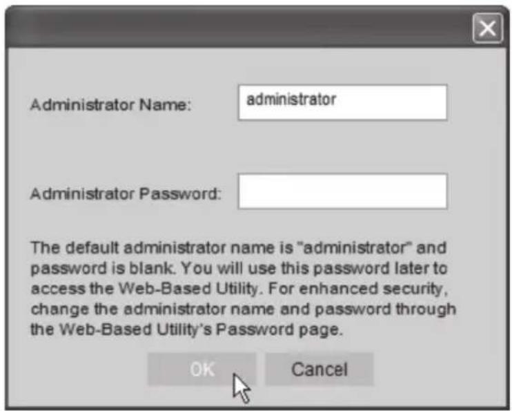
- In the following dialogue box you will set the time zone and date. You can also give a name and description for the camera. Enter your settings and click ▶.

- Select the camera to use a fixed IP address (Fixed IP address) or to automatically obtain an IP address (Dynamic IP address) from e.g. a router with DHCP function. Make your selection and click ▶.

-
If you have previously chosen to give the camera a fixed IP address the TCP/IP Settings will appear in the dialogue box.
-
Enter an available IP address, Subnet Mask and Default Gateway for your network.
- Fill in a Primary DNS and a Secondary DNS if you wish to use the e-mail and DNS functions. Refer to the information provided by your Internet service provider.
- Click ▶ next to continue.
N.B. Write down the IP address; you will need it later to configure the camera.

- The following dialogue box shows the settings you have just entered. Click ▶.

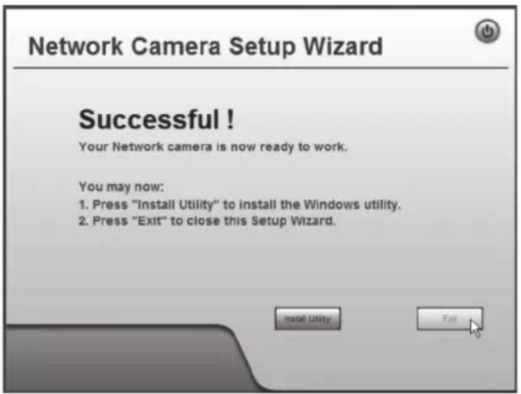
- Click OK to save and then OK again.

- Click Exit to complete the installation.
6. Show the camera image via the web browser
The camera shows video in real time via the camera's web interface.
Real time video can only be shown if the web browser is ActiveX 8.0 compatible (e.g. Internet Explorer 6.0).
- Start the computer's web browser and enter the camera's IP address (in this case http://192.168.1.37) and press Enter.
Tip! Add this page to the web browser's favourites/bookmarks!
- Click on View Video.

- Check the picture quality and change the picture's properties with the controls on the screen.
Obs!
- Real time video can only be shown if the web browser is ActiveX 8.0 – compatible (e.g. Internet Explorer 6.0).
- You must accept and install the Active X component when requested in the web browser window.
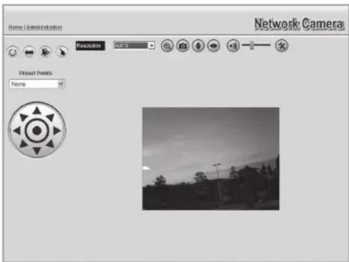
Explanation of buttons and functions:
| AUTO | Selects the camera resolution/picture size |
 | Zooms in |
 | Takes a snapshot |
 | Rotates the picture vertically |
 | Rotates the picture horizontally (mirror image) |
 | Turns on/off the microphone sound |
 | Adjusts the microphone's sound level |
 | Setup |
 | Controls the camera's position |
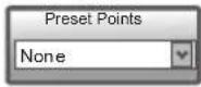 | Preset positions |
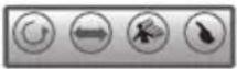 | Automatic switching/Automatic panning/Motion detector/Quick panning |
7. Configuration via the web browser
7.1 Opening the configuration interface
- Start the computer's web browser and enter the camera's IP address (in this case http://192.168.1.37) and press Enter.
Tip! Add this page to the web browser's favourites/bookmarks!


-
Click on Administration to access the control panel.
-
In order to change the camera's settings the correct password must be entered. Log in with the preset username and password:
User name: administrator Password: (no password)

- In the menu to the left, configuration interface options are shown.

- The configuration is divided into submenus which are described in the 7.2 Setup section.
- Enter your desired settings and click on Save to save your settings. You can at any time click on Help to read the help section for each respective.
7.2 Setup
7.2.1 System

| System Settings | |
| Camera Name Enter a desired | ed name for the camera. |
| Description Enter a desired | description for the camera. |
| Date & Time | |
| Time Zone Choose time zone. | |
| Network Time Protocol Check to synchronize the clock against an Internet-time server. | |
| NTP Server Address Does not normally have to be changed(preset address: clock.via.net). | |
| Update Enter the interval for time synchronization. | |
| LED Operation Deselect to turn off the LEDs on the camera's front(for discrete surveillance). | |
7.2.2 Network

| IP Address Configures the camera's IP address. | |
| Obtain an IP address automatically (DHCP) | Receive an IP address automatically from a DHCP server. |
| Use the following IP address Give the camera its own IP address. | |
| DNS Server Address Enter desired | DNS servers. Normally the router's DNS setting can be used, then type in the router's IP address here. |
| Secondary Port Select to activate | a secondary http port for access to the camera (if port 80 is used for another application). Enter desired port number. |
| RTP/RTSP RTSP (Real-time Streaming Protocol):Indicates port for streaming of media over the Internet.RTP (Real-time Transport Protocol):Indicates port for streaming in real time of sound and picture over the Internet. | |
| Multicast RTP/RTSP Select to activate | Multicast. Enter address and port number for video and sound. |
| UPnP Select to activate UPnP. | |
| QoS Activates QoS. | |
7.2.3 Wireless
Configures the camera for use in a wireless network. Select network type, SSID (name of network) and the network's security settings. Enter the same information you gave for other wireless devices which also communicate on the wireless network. Contact the network administrator for assistance if you do not own the network yourself.
Connect the camera to a wireless network
- Connect and configure the camera according to section 4 & 5.
- Go to the Wireless menu and enter the settings for your wireless network. Select Save in order to save your settings and then close your browser.
- Detach the network cable and restart the camera by disconnecting it from, and then reconnecting to the adaptor.
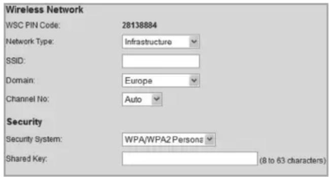
If you are satisfied with the settings, connect the camera to network after it has been restarted.
| Wireless Network | |
| Network Type | Select the type of wireless network you will be connecting the camera to. Infrastructure – If you are connecting to a wireless router/access point. Ad-hoc – Peer to peer network. |
| SSID Enter the | network's SSID (network name). The name must correspond to the network's SSID. |
| Domain Select | your region from the drop-down list. |
| Channel No Auto | - Chooses a channel automatically (selected automatically when connecting to a router/access point). 1-13 – Only used when connecting to an Ad-Hoc network. Select the same channel as the other wireless stations which the camera connects to. |
| Security | |
| Security System | Use the same security settings as the wireless network you will be connecting to. Disabled – No security is in use, the wireless network is available for all connections. WEP – Select the network you wish to be protected by WEP. WPA/WPA2 Personal – Choose the wireless network you wish to be protect by a WPA key. |
7.2.3 DDNS

If you are provided with a dynamic IP address from your Internet provider instead of a permanent IP address you may with help of a dynamic DNS server connect a domain name to your external IP address.
The camera automatically contacts and updates the DNS server with the new IP address if your Internet connection is given a new IP address. The dynamic domain name always updated to your IP address in that way.
An example of Dynamic DNS sever is dyndns.org where you can register for free for a dynamic domain name.
N.B.
If your router has its own function for dynamic dns it can be used instead of the camera's ddns service.
| Enable DDNS Select to activate the feature. | |
| Service Provider Choose in | the list the dynamic dns server you are using. |
| Web Site Click to open the website for chosen dns server. | |
| Domain (Host) Name Type in your dynamic domain name. | |
| Account/E-Mail Username/login name for the account. | |
| Password/Key Password for the account. | |
| Check WAN IP Address Enter how often the camera should search for changed IP address. | |
7.3.2 Video Access

| User Access Protects access to the camera. The users must enter a username and password to access to the camera. Add the users in the User Database menu. | |
| Video Access Activate scheduled access to the camera. Access to the camera is only given during specified times.NB: Regardless of setting the administrator always has access to the camera. | |
| Access Schedule | |
| Delete Removes marked schedules from the list. | |
| Add New Schedule | |
| Day Choose desired days to be scheduled. | |
| Start Time Enter a start time. | |
| End Time Enter a stop time. | |
| Add Adds a schedule to the list. |
7.3.3 User Database
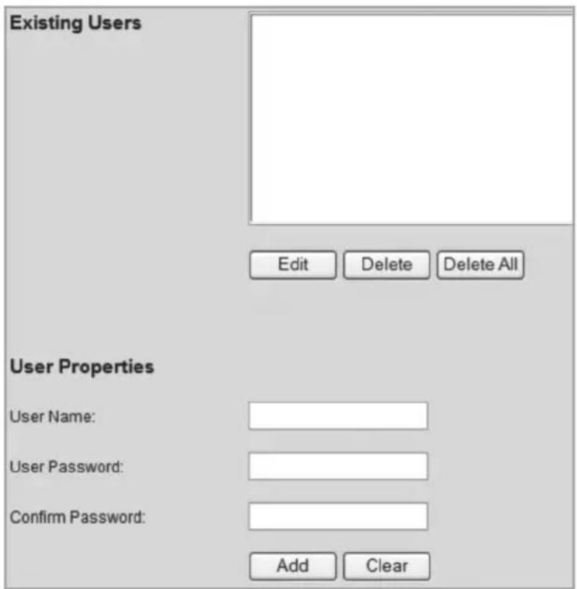
| Existing Users | |
| Edit Edits users. | |
| Delete Removes users. | |
| Delete All Removes all users. | |
| User Properties | |
| User Name Type in desired | username. |
| User Password Password for the user. | |
| Confirm Password Confirm | the password one more time. |
| Add Adds the user to the user database. | |
7.3 Video & Audio
7.3.1 Video & Audio
| MPEG-4 Settings | |
| Resolution The camera's picture resolution. | |
| Video Quality Control | Constant Bit Rate: Choose desired Bit Rate. Fixed Quality: Choose picture quality. |
| Max Frame Rate Choose frames per second. | |
| MJPEG Settings | |
| Resolution The camera's picture resolution. | |
| Fixed Video Quality | Choose picture quality. |
| Max Frame Rate Choose frames per second. | |
| Mobile Settings | |
| Enable Mobile Streaming | See section 8.2 Streaming to the mobile phone. |
| Video Adjustments | |
| Power Line Frequency | Choose the frequency that corresponds with the power supply's frequency (with fluorescent tube lighting). |
| White Balance Indicates the white balance. | |
| Lighting Condition | Lighting conditions. |
| Brightness Light intensity. | |
| Sharpness Sharpness. | |
| Options | |
| Enable Microphone | See section 9.4 Using the microphone and speakers. |
| Enable Speaker | |
| Flip Turns the picture upside down. | |
| Mirror Mirrors the picture. | |
| Enable Time Stamp | Adds current time to the picture. |
| Enable Text Display | For (camera) identification when several cameras are being used. Type in desired text to be displayed in the picture (up to 20 characters). |

7.4 Event
7.4.1 Motion Detection

See the section 8.3 Motion Detection.
7.4.2 E-mail

E-mail settings for sendig images as an attached file to one or several e-mail addresses.
• See the settings for e-mail that you received from your Internet provider.
| Primary SMTP Server | |
| SMTP Server Address Enter | the SMTP-address which is used to send e-mail.* |
| Authentication Indicates if the | SMTP-server requires authorization. |
| SMTP Login Name Username | (only at authorization). |
| SMTP Password Password | (only at authorization) |
| POP server name Only at authorization. | |
| Show "From" as Type in the | e-mail address which is shown in the“from” field when the e-mail reaches the receiver. |
| Secondary SMTP Server | |
| Enter settings for a secondary SMTP-server if the primary SMTP-server cannot be reached. | |
| E-mail Setup | |
| E-mail Address Enter at least one e-mail address to send an image to. | |
| Subject Indicate a subject for the e-mail. | |
* Some Internet providers require that a special SMTP-server is used if you have your own e-mail server or if you are using e-mail from an external provider. Contact your Internet provider.
7.4.3 FTP
Settings for automatic uploading of images to an FTP-server.
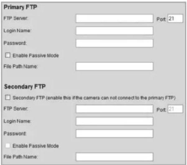
| Primary FTP | |
| FTP Server The FTP-server's address. | |
| Port The FTP-server's port number (usually 21). | |
| Login Name Username. | |
| Password Password. | |
| Enable Passive Mode Select to activate passive mode. | |
| File Path Name Indicates to which catalogue the picture file will be saved. | |
| Secondary FTP | |
| Enter settings for a secondary FTP-server if the primary FTP-server cannot be reached. | |
7.4.4 HTTP
Settings for HTTP notification.

| HTTP Notification | |
| Enable Select to activate the | feature. |
| URL Enter the server's URL. | |
| Proxy Server Name Possible | proxy server for indirect connection. |
| Port Number Enter the proxy | server's port number. |
| Method Choose method for | http notification. GET or POST. |
7.4.5 Event Trigger
Sets schedule for trigger events and method of notification, via e-mail, FTP, or HTTP.

| Event Schedule | |
| Displays created event schedules. | |
| New Schedule | |
| Effective Time Frame Indicates which days the schedule will be valid for. | |
| Day Choose desired schedule days. | |
| Start Time Enter a start time. | |
| End Time Enter a stop time. | |
| Add Adds a schedule to the list. | |
| Trigger Event | |
| Motion Detection Select to activate motion detection.Detection of movement. | |
| Actions Select method of notification: E-Mail, FTP or HTTP. | |
| Attachment Type Choose type of attached file: JPEG picture or video. |
7.5 Administration
7.5.1 Maintenance
General settings for password administration, software upgrades, backups and resetting.
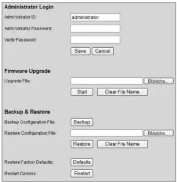
| Administrator Login | |
| Administrator ID Changes the preset administrator name(preset username: administrator) which is used at login. | |
| Administrator Password | Indicates a password for administrator login. |
| Verify Password Verify | the password by retyping it. |
| Firmware Upgrade | |
| Upgrade File Click on Browse to choose an upgrade file for upgrading the camera's software. | |
| Start Click on Start to start the upgrading. The camera restarts when the upgrading is done. | |
| Clear File Name Clears | the Upgrade File field. |
| Backup & Restore | |
| Backup Click on Backup | to save the camera's current configuration to a text file. |
| Restore Configuration File | Click on Restore to resume the configuration file. |
| Restore Factory Defaults | Resets the camera to factory settings. |
| Restart Camera Push to restart the camera. | |
7.5.2 Status
Displays the camera's software version and the camera's network and video settings.
| System | |
| Device Name: | Camera1 |
| Description: | |
| FW version: | V1.0.04 |
| Network | |
| MAC Address: | 00:c0:02:90:df.29 |
| IP Address: | 192.168.1.37 |
| Network Mask: | 255.255.255.0 |
| Gateway: | 192.168.1.1 |
| MPEG-4 | |
| Resolution: | 640*480 |
| Video Quality: | Very High |
| Frame Rate: | 30 |
| MJPEG | |
| Resolution: | 640*480 |
| Video Quality: | Very High |
| Frame Rate: | 30 |
7.5.3 Log
Displays the camera's log file for settings and events.

8. Advanced use
8.1 Connecting the camera via the Internet
If the camera is installed on the network behind e.g. a router, the router must be configured in order for the camera to be reached from the Internet.
8.1.1 Prepare your router/firewall
- If you are using e.g. a router or a firewall in your network it is necessary that the camera's ports are opened in the router/the firewall and is directed to the camera's internal IP address. See the router's/firewall's instruction manual for help.
- Preset port number to connect the camera is: 80.
If you want to connect with a different port number a secondary port number is entered in the Setup > Network menu.
Secondary Port:

Enable HTTP Secondary Port
1024
(1024-65535)
- You also have to find the IP address for your Internet connection. A simple way of doing this is to enter "What's My IP" as search word in a search engine for links that show your external IP address.
8.1.2 Connect to the camera
- Start the computer's web browser and type in the Internet connection's IP address (http://xxx.xxx.xx.xx) and press Enter.
N.B.
This can usually not be done from a computer on the same network as the camera. Use a computer on another network or another Internet connection to connect the camera (from the internal network you would instead connect to the camera's internal IP address).
- Click on View Video to show the camera image or choose Administration to configure the camera.
8.2 Streaming to a mobile phone
The camera picture can be streamed to most 3G mobile phones that support video streaming via the RTSP protocol.
8.2.1 Prepare the camera for streaming to a 3G mobile phone

- Select the option Enable Mobile Streaming in the Video and Audio menu.
- Choose video quality (Constant Bit Rate) and picture frequency (Max Frame Rate).
- Enter any code of choice for the camera (Access Code), but in this case 1234. This code will then be entered at the end of the web address you indicate in your mobile phone.
- Click Save to save your settings.
NB:
- If you are using e.g. a router or a firewall in your network it is necessary that the camera's ports are opened in the router/firewall and is directed to the camera's internal IP address. See the router's/firewall's instruction manual for help.
- The preset port numbers for video streaming can be changed in the camera's network settings in the menu Setup > Network:

Preset ports in the camera:
RTSP: 554 (TCP)
RTP: 5000 (UDP)
You also have to find the IP address for your Internet connection. A simple way of doing that is to enter "What's My IP" as search word in a search engine for links that show your external IP address.
8.2.2 Connecting to the camera with a 3G mobile phone
- In the mobile phone's web browser enter rtsp:// followed by the camera's/router's external IP address followed by the access code.
Example: rtsp://XXX.XXX.XXX.XXX/1234 where X stands for the camera's external IP address and 1234 is the access code.
- If the camera and the router/firewall are correctly configured the camera picture will be displayed in the mobile phone.
Important!
The mobile phone must support the RTSP protocol to be able to receive the camera's video streaming. Follow the mobile phone's instruction manual. Your mobile phone plan must also be activated for data traffic via the 3G net.
8.3 Motion detection
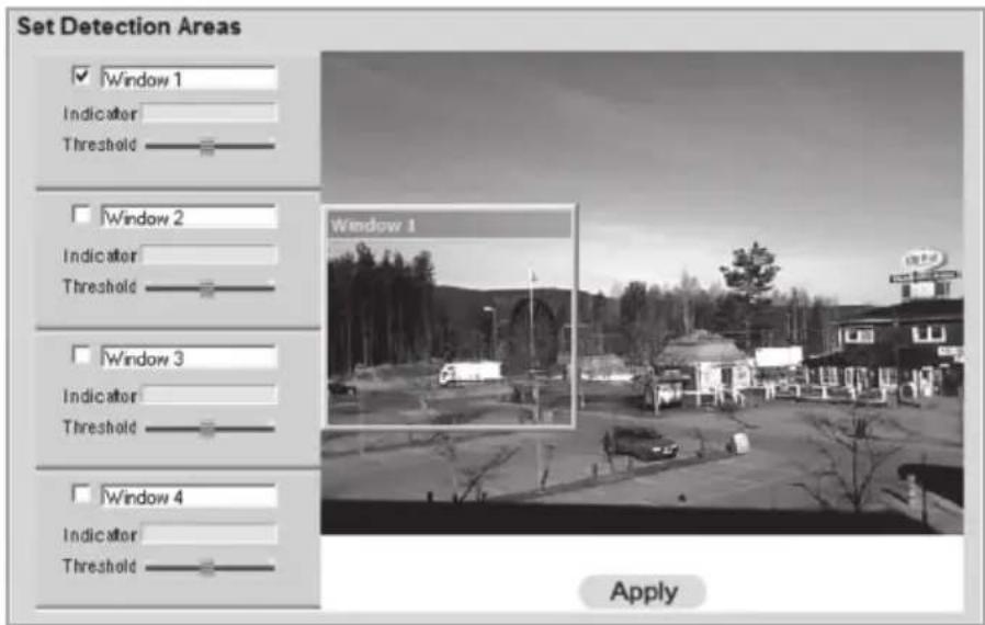
NB: Motion detection can besides detectin moving objects also react to quick light changes. It is therefore recommended that the feature is only used on cameras used indoors.
- Select the box for one or several areas (Window 1-4). Up to four detection areas can be defined for detection of movement.
- Use the cursor to move each detection area to the area or areas the motion detector should react to.
- Adjust the (Threshold) for the detection.
- Click on Apply to confirm your settings.
- Follow section 7.4.2 E-mail to set one or several e-mail addresses to send the picture to.
- Activate Motion Detection, type of event (e-mail, FTP, or http) and type of attached file in the menu Event Trigger (see section 7.4.5).
9. Monitor Manager
With the included programme Monitor Manager several other cameras can be monitored simultaneously.
9.1 Installation
The installation guidelines applies to Windows XP with Service pack 2 installed.
- Connect the camera according to the instructions in section 4.
- Insert the supplied CD into the computer's CD-ROM drive. If the installation does not start automatically, use the file NetworkCamera.exe application found directly under the root folder on the CD-ROM.
- When the installation programme has started a welcome screen is displayed. Click on Install Utility to begin the installation.
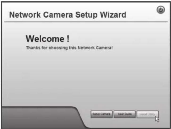
- Click on Next to continue.

- Click on Browse if you wish to install the programme in another folder than the one suggested, otherwise click Next.
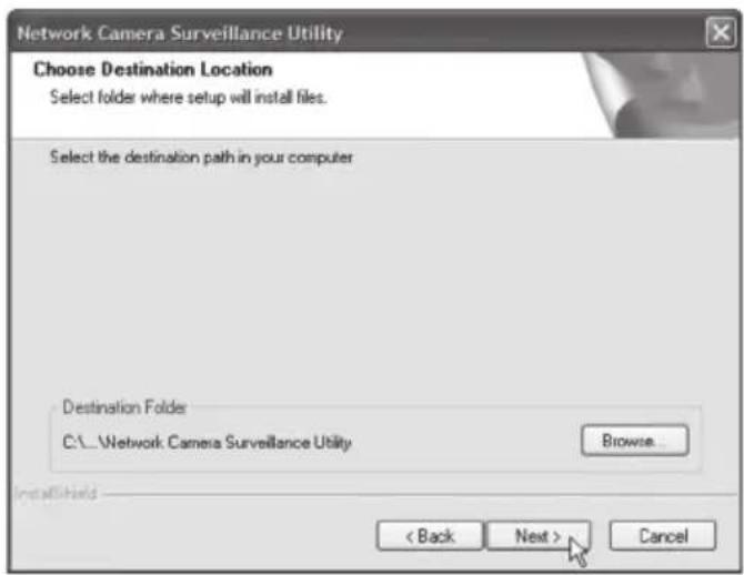
- Click Next to confirm.

- Click Finish to complete the installation. The programme will start automatically.
9.2 Use Monitor Manager
9.2.1 Connect to the camera and display the camera picture
To display the camera in the programme it must first be connected and given its own channel number.
- Install and start the programme according to the instruction in step 7.1.

- Click on to change the programme's properties and search for the camera on the network.
- Select Lan (the camera should be listed) and click on Refresh to search for connected cameras.
- Select the camera on the list.
- Give the camera a channel number (in this case 1) and click on Add to add the camera in the list.
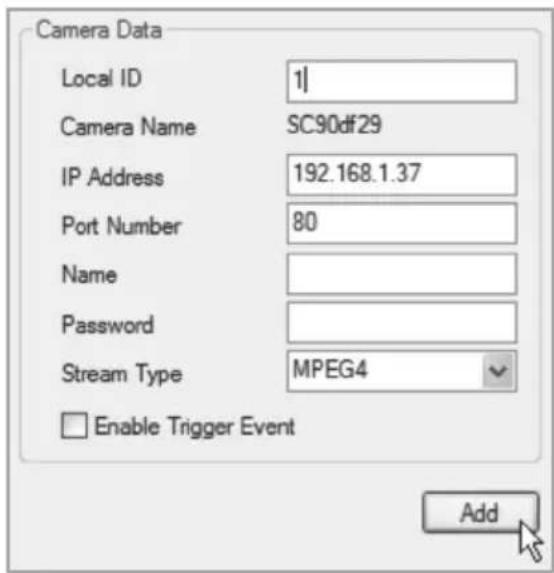

- Click Exit to close down the dialogue box.
- Press ▶ to start the playback. The camera picture should now be displayed in the programme.

Explanation of the programme's controls and features
| Button Function | ||
 | Channel Displays the chosen camera's channel number. | |
 | Play Starts playback for the chosen camera. | |
 | Pause Freezes the picture. | |
 | Stop Stops playback. | |
 | Record | Push to record current picture. White recording the button changes colour to red. |
 | Snapshot Push to take a snapshot of the camera picture. | |
 | Zoom | Click on the icon and then click in the area of the picture that you want to enlarge. |
 | Flip Rotates the picture horizontally. | |
 | Mirror Mirrors the picture. | |
 | Sound On/Off | Turns the sound on or off (can only be chosen when the function is activated according to section 9.4). |
 | Microphone On/Off | Turns the microphone on or off (can only be chosen when the function is activated according to section 9.4). |

Camera Indicators
Used to quickly choose between connected cameras.
Also displays status for chosen camera.
Column 1 Green indicator is displayed when the camera is available.
Column 2 Red indicator indicates when recording is in session.
Column 3 Yellow indicator is displayed when the motion detector is activated.
Column 4 and 5 Indicates I/O-status.
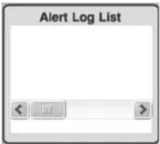
Alert Log List
Shows history of possible alarms during motion detection.
 | Setup | - Searches and connects network connected cameras. - Sets scheduled recordings. - Changes recording properties. |
 | Playback | Opens the programme for playback of recorded sequences. Refer to the 7.4 Playback section. |
 | One Video Layout Displays the selected camera only. | |
 | Four Video Layout | - Displays up to four cameras simultaneously (if more than one camera is connected). - Use "drag and drop" to move the image to the desired screen section. |
 | Six Video Layout | - Displays up to six cameras simultaneously (if more than one camera is connected). - Use "drag and drop" to move the image to the desired screen section. |
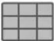 | Nine Video Layout | - Displays up to nine cameras simultaneously (if more than one camera is connected). - Use "drag and drop" to move the image to the desired screen section. |
9.3 Recording playback
Recording can be done simultaneously with playback, or according to a recording schedule.
9.3.1 Preparing the computer for recording
1. Click on Setup
to change the programme's settings.
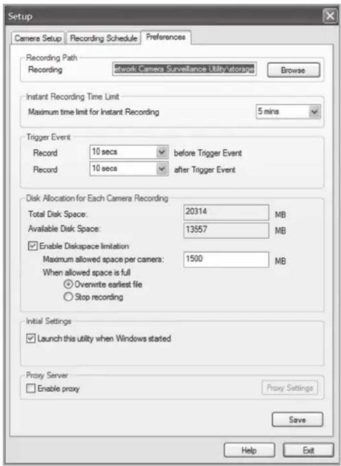
- Select the Preferences tab and enter the desired settings:
■ Recording Path – Choose a folder where the recordings will be stored.
- Instant Recording Time Limit – Enter a max. time limit for recording.
■ Trigger Event
- before Trigger Event – Enter a time a recording should start before motion is detected. The programme can save up to 30 seconds of recording in memory before a trigger event.
- after Trigger Event – Set a time for recording after motion is detected.
-
Disc Allocation for Each Camera Recording – Displays the amount of disk space allocated to each camera.
■ Initial Setting – Select if you wish the programme to start when starting Windows.
■ Proxy Server – Enter proxy settings when using a proxy server. -
Click on Save to save your settings and Exit to return to Monitor Manager.
9.3.2 Scheduling recording


- Click on Setup to change the programme's settings.
- Select the Recording Schedule tab to create a recording schedule. Enter desired settings for the following:
■ Local ID – Select the camera to record.
■ Interval – Select the interval for recording.
■ Start Date – Start date for recording.
■ Start Time – Start time for recording.
■ Duration – Select length of recording (up to 24 hours).
- Click Add to save the newly created schedule on the recording schedule list. The programme will now automatically start recording according to the programmed schedule.
- Repeat steps 2-3 if you wish to add more recording schedules.
N.B.
In order for the recording schedule to function the Recorder programme must be started. The Recorder programme starts automatically when the Monitor Manager programme starts, and continues to be active even when Manager becomes inactive.
9.3.3 Playing back recorded files
- Click on
to open the video player.
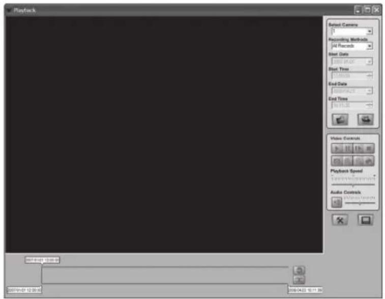

Explanation of control functions:
| Select Camera Select a | desired camera number. |
| Recording Methods Select the type of recording to be viewed. | |
| Start Date/Time Enter the date and time you want to begin showing the recording. | |
| End Date/Time Enter the date and time you wish to end the showing of the recording. | |
| Load other Cameras Load additional cameras from the network. | |
| Submit Start playback according to the above settings. | |
| Play Resumes playback after stopping or pausing | |
| Pause Temporarily | stops/freezes playback |
| Frame by Frame | Each mouse click progress video sequences frame by frame |
| Stop Stops playback | |
| Snapshot Takes a | snapshot from the video sequence |
| Zoom In Enlarges | the image |
| Zoom Out Reduces the image | |
| Prints out the current image | |
| Playback Speed Regulates playback speed | |
| Audio Controls Volume control | |
| Setup Changes programme settings | |
| Monitor Opens the | Monitor Manager programme |
| Convert Converts selected video sequence to AVI-format | |
| Delete Erases selected video sequence | |


9.4 Using the microphone and speakers
The camera is equipped with a built-in microphone for audio monitoring.
Audio is played back on the computer at the monitoring location.
9.4.1 Activates the camera's microphone

- Select the Enable Microphone alternative in the Video & Audio menu.
- Click on Save to save your settings.
- Click on View Video to display the camera image. Audio from the camera's microphone is played on the computer's speakers.

9.4.2 Activating the camera's speaker output
- Connect the speaker (e.g. a computer speaker) to the outlet marked SPKR Out (3.5 mm mono) at the back of the camera.
- Connect a computer microphone to the computer's mic. outlet.
- Select the Enable Speaker alternative in the Video & Audio menu.
- Click on Save to save your settings.
- Click on View Video to display the camera image. Audio from the microphone should now be heard from the speaker.
10. Care and Maintenance
Use a soft moist cloth to clean the product.
Never use strong detergents or solvents for cleaning.
11. Troubleshooting
It is not possible to connect to the camera/the programme does not have any contact with the camera
- Make sure that your computer's firewall is not blocking the camera's connection to the network. Turn off or reconfigure your firewall.
- Make sure that the IP address you have given to the camera corresponds to the newtork's series of IP addresses. Connect the camera and run the configuration programme again.
- Make sure that the network cable you are using is undamaged and of the same type that was included with the camera.
- Shortly disconnect the camera from the power source, reconnect and try again.
- Try to restart the camera by pressing the reset button on the camera's underside.
There is no connection between the camera and the wireless network
- Connect the camera with network cable and check the settings for your wireless network.
- Make sure that you have given the right security settings for your wireless network. Contact the network administrator for assistance if you do not own the network yourself.
- Try to connect another wireless device in order to make sure that your connection settings are proper and that the wireless network is functioning.
12. Disposal
When it is time to dispose of the product, dispose of it according to your local ordinances. If you are unsure please contact your municipality.
13. Specifications
Power supply 5 V DC, 2 A (via included adaptor)
Network LAN/WLAN with support for TCP/IP, SMTP, SHCP, HTTP, DDNS 802.11b/g (WPA2-PSK, WEP, 64/128 bits security)
Network connection Ethernet 10/100BaseT (RJ45)
Lens F4.6 mm @ F1.89 Fixed Focus
Max. resolution 640 x 480 (VGA)
Dimensions 90 x 35 x 90 mm (W x H x L)
Operating temperature 0 °C to 40 °C
Storage temperature 0 °C to 40 °C
Declaration of Conformity

Hereby, Clas Ohlson AB declares that following product(s):
Wireless IP-CAMERA
36-2914/18-2062
RC8030/RC8030-UK
is in compliance with the essential requirements and other relevant provisions of Directive 1999/5/EC.
Article 3.1a (Safety): EN 60950-1 EN 50385
Article 3.1b (EMC): EN 301489-1 EN 301489-17
Article 3.2 (Radio): EN 300328

Insjön, Sweden, June 2008

Klas Balkow President
Clas Ohlson, 793 85 Insjön, Sweden
SVERIGE
KUNDTJÄNST Tel: 0247/445 00
Fax: 0247/445 09
E-post: kundtjanst@clasohlson.se
INTERNET www.clasohlson.se
BREV Clas Ohlson AB, 793 85 INSJÖN
NORGE
KUNDESENTER Tlf.: 23 21 40 00
Faks: 23 21 40 80
E-post: kundesenter@clasohlson.no
INTERNETT www.clasohlson.no
POST Clas Ohlson AS, Postboks 485 Sentrum, 0105 OSLO
SUOMI
ASIAKASPALVELU Puh: 020 111 2222
Faksi: 020 111 2221
For consumer contact, please visit
www.clasohlson.co.uk and click on
customer service.
INTERNET www.clasohlson.co.uk

- Wireless IP Camera
- Article number 36-2914 Model RC8030
- 18-2062 RC8030-UK
- Table of Contents
- Safety
- Product Description
- Features
- Internet functions
- Safety Features
- System requirements
- The package contains
- Features
- Front of camera
- Back of camera
- Mounting & Installation
- Mounting the aerial
- Mounting the camera
- Connecting the network cable
- Switching on the camera
- LED Indicators
- Basic Setup
- Configuring the camera
- Show the camera image via the web browser
- Obs!
- Configuration via the web browser
- Opening the configuration interface
- Setup
- System
- Network
- Wireless
- Connect the camera to a wireless network
- DDNS
- N.B.
- Video Access
- User Database
- Video & Audio
- Video & Audio
- Event
- Motion Detection
- FTP
- HTTP
- Event Trigger
- Administration
- Maintenance
- Status
- Log
- Advanced use
- Connecting the camera via the Internet
- Prepare your router/firewall
- Connect to the camera
- Streaming to a mobile phone
- Prepare the camera for streaming to a 3G mobile phone
- NB:
- Preset ports in the camera:
- Connecting to the camera with a 3G mobile phone
- Important!
- Motion detection
- Monitor Manager
- Installation
- Use Monitor Manager
- Connect to the camera and display the camera picture
- Explanation of the programme's controls and features
- Camera Indicators
- Alert Log List
- Recording playback
- Preparing the computer for recording
- Click on Setup
- Scheduling recording
- Playing back recorded files
- - Click on
- Using the microphone and speakers
- Activates the camera's microphone
- Activating the camera's speaker output
- Care and Maintenance
- Troubleshooting
- It is not possible to connect to the camera/the programme does not have any contact with the camera
- There is no connection between the camera and the wireless network
- Disposal
- Specifications
- Declaration of Conformity
- SVERIGE
- NORGE
- SUOMI
Brand : Clas Ohlson
Model : 36-2914
Category : Security Camera