
EZHD-TRF8 - Voice recorder KT&C - Free user manual and instructions
Find the device manual for free EZHD-TRF8 KT&C in PDF.


| Product Type | Digital Voice Recorder |
| Brand | KT&C |
| Model | EZHD-TRF8 |
| Dimensions (approx.) | 10 x 5 x 2 cm |
| Weight (approx.) | 100 g |
| Power Supply | USB rechargeable battery (5V DC) |
| Recording Format | MP3 / WAV |
| Storage Capacity | 8 GB internal memory (expandable via microSD) |
| Recording Modes | High-quality, long-play, voice-activated |
| Playback | Built-in speaker and headphone jack |
| Battery Life | Up to 20 hours (continuous recording) |
| Interface | USB 2.0 for file transfer |
| Display | LCD screen with time and settings |
| Microphone | Built-in omnidirectional |
| Noise Reduction | Advanced noise cancellation |
| Maintenance | Keep dry; clean with a soft cloth; avoid extreme temperatures |
| Safety | Do not disassemble; use only approved charger; keep away from water |
| Spare Parts / Repairability | Contact KT&C support for battery or charger replacement |
Frequently Asked Questions - EZHD-TRF8 KT&C
User questions about EZHD-TRF8 KT&C
0 question about this device. Answer the ones you know or ask your own.
Ask a new question about this device
Download the instructions for your Voice recorder in PDF format for free! Find your manual EZHD-TRF8 - KT&C and take your electronic device back in hand. On this page are published all the documents necessary for the use of your device. EZHD-TRF8 by KT&C.
USER MANUAL EZHD-TRF8 KT&C
Triple Technology Recorders
960H - EZHD - IP


EZHD-TVL4/EZHD-TVL8/EZHD-TVL16

Regulatory information FCC information
FCC compliance: This equipment has been tested and found to comply with the limits for a digital device, pursuant to part 15 of the FCC Rules. These limits are designed to provide reasonable protection against harmful interference when the equipment is operated in a commercial environment. This equipment generates, uses, and can radiate radio frequency energy and, if not installed and used in accordance with the instruction manual, may cause harmful interference to radio communications. Operation of this equipment in a residential area is likely to cause harmful interference in which case the user will be required to correct the interference at his own expense.
FCC conditions
This device complies with part 15 of the FCC Rules. Operation is subject to the following two conditions:
-
This device may not cause harmful interference.
-
This device must accept any interference received, including interference that may cause undesired operation.
EU Conformity Statement

This product and - if applicable - the supplied accessories too are marked with "CE" and comply therefore with the applicable harmonized European standards listed under the Low Voltage Directive 2006/95/EC, the EMC Directive 2004/108/EC, the RoHS Directive 2011/65/EU.

2012/19/EU (WEEE directive): Products marked with this symbol cannot be disposed of as unsorted municipal waste in the European Union. For proper recycling, return this product to your local supplier upon the purchase of equivalent new equipment, or dispose of it at designated collection points. For more information, see: www.recyclethis.info.

2006/66/EC (battery directive): This product contains a battery that cannot be disposed of as unsorted municipal waste in the European Union. See the product documentation for specific battery information. The battery is marked with this symbol, which may include lettering to indicate cadmium (Cd), lead (Pb), or mercury (Hg). For proper recycling, return the battery to your supplier or to a designated collection point. For more information see: www.recyclethis.info.
Preventive and Cautionary Tips
Before connecting and operating your device, please be advised of the following information:
- Ensure that the unit is installed in a well-ventilated, dust-free environment.
• These units are designed for indoor use only. - Keep all liquids away from the recorder.
- Ensure environmental conditions meet factory specifications.
- Ensure that the unit is properly secured to a rack (depending on model) or shelf. Major shocks or jolts to the unit as a result of dropping it may cause damage to the sensitive electronics within the unit.
- Use the device in conjunction with an UPS if possible.
- Powering down the unit before connecting and disconnecting accessories and peripherals is recommended.
• A factory recommended HDD should be used for this device. - Improper use or replacement of batteries may result in risk of explosion or other hazards. Replace batteries with the same or equivalent type only. Dispose of used batteries according to the instructions provided by the battery manufacturer.
Trademarks and Registered Trademarks
- Windows and Windows mark are trademarks or registered trademarks of Microsoft Corporation in the United States and/or other countries.
• HDMI, HDMI mark and High-Definition Multimedia Interface are trademarks or registered trademarks of HDMI Licensing LLC.
• The products contained in this manual are authorized by HDMI Licensing LLC with the use right of the HDMI technology.

HIGH-DEFINITION MULTIMEDIA INTERFACE
• VGA is the trademark of IBM.
- UPnP ^TM is a certification mark of the UPnP ^TM Implementers Corporation.
- Other names of companies and product contained in this manual may be trademarks or registered trademarks of their respective owners.
Thank you for purchasing our product. If there is any question or request, please do not hesitate to contact your dealer. KT&C Certified Dealers can contact KT&C directly.
This manual is applicable to the EZHD Series HD-TVI digital video recorders. It is based on the features and functions incorporated in V3.0.4 firmware. Please consult the KT&C website for updated firmware and descriptions of new features and functions which may have been added via new firmware releases.
This manual may contain inadvertent technical discrepancies or printing errors; also, as KT&C reserves the right to update and improve our products, the content is subject to change without notice. Updates describing changes will be added into new versions of this manual as soon as practical, and additional information may be posted to our website, in technical bulletins, or distributed by other means.
Product Key Features
General
- Connectable to both HD-TVI and analog cameras with automatic format detection/adjustment
● Up-the-cable control of cameras that respond to Coaxitron type signaling - One (EZHD-TVL4) or two (all other models) bonus OMNI IP Plug-and-Play channels without sacrificing any BNC connected channels
- Each channel supports dual-stream recording. Main stream supports up to 1080p resolution and sub-stream supports up to WDI resolution
- Independent configuration for each stream for each channel, including resolution, frame rate, bit rate, image quality, etc.
● Audio and video synchronization during composite video/audio stream encoding
● Watermark technology to validate and/or detect modification of exported video
Local Monitoring
● Simultaneous HDMI, VGA and CVBS outputs (no CVBS output for EZHD-TVL4/8/16 models)
- HDMI output and VGA output at up to 1920*1080 resolution;
● 1/4/6/8/9/16 camera live view screens, with control of camera placement and sequencing
● Selected live view channels can be hidden (covert)
● Motion detection, video-tampering detection, video exception alarm and video loss alarm functions
- Privacy masking
● Several PTZ protocols are supported, including PTZ preset, patrol and pattern
- Zoom in/out by mouse click, and PTZ movement by dragging mouse pointer
HDD Management
- For EZHD-TVL4 and EZHD-TVL8, 1 SATA hard disk can be connected For EZHD-TVL-16 up to 2 SATA hard disks can be connected For EZHD-TRF4/8/16 models 4 SATA hard disks and 1 eSATA disk can be connected (Each disk with a maximum of 4TB storage capacity.)
- 8 network disks (8 NAS disks, or 7 NAS disks+1 IP SAN disk) can be connected
- For recording or backup eSATA disks are supported
● S.M.A.R.T. diagnostics and bad sector detection are supported
- HDD sleep function is supported
- HDD properties include redundancy (with multiple disks), read-only, read/write (R/W);
- HDD group management (with multiple disks)
- HDD quota management; different capacities can be assigned to different channels
Recording and Playback
● Holiday recording schedule configuration
● Overwrite and non-overwrite recording modes
- Separate normal and event video recording parameters
● Multiple recording types: manual, continuous, alarm, motion, motion | alarm, motion & alarm
● 8 recording time periods with individual record types
● Pre-record and post-record for motion detection triggered recording, and pre-record for schedule and manual recording
- Search record files by event type (alarm input/motion detection)
- Customization of tags, with search and playback back by tags
- Locking and unlocking of record files
- Local redundant recording
- Search and playback of record files by camera number, recording type, start time, end time, etc.
● Smart playback to skip through periods where the is no motion in scene
● Digital zoom in for any area during playback - Reverse playback of multi-channel views
- Pause, fast forward, slow forward, skip forward, and skip backward during playback; scroll through video by dragging the mouse on the progress bar;
● Up to 16-ch synchronous playback at 1080p
Backup
- Export data to a USB, SATA or eSATA device (for models with eSATA ports)
● Export video clips during playback
● Management and maintenance of backup devices
Alarm and Exception
- Configurable arming time schedule for alarm input/output (for models with alarm I/O)
- Alarm for video loss, motion detection, video tampering, abnormal signal, video input/recording resolution mismatch, illegal login, network disconnect, IP address conflict, record exception, HDD error, and HDD full, etc.
- Alarms can trigger full screen display, audio alarm, notification to CMS PC, sending email and alarm output (for models with alarm I/O)
● Automatic restore when system returns to normal
Other Local Functions
● Manual and automatic video quality diagnostics
- Users can operate the system using a mouse and/or IR remote control
- Three-level user management; admin ID can create many other accounts and define their operating permissions, which includes per-channel access control
- Log search and export for various types of operation, alarm/event and exception entries
● Manually triggering and clearing of alarms
- Import and export of device configuration information
● Automatic determination of connected camera signal type
Network Functions
● Self-adaptive network interface 10M/100M for EZHD-TRF4/8, 10M/100M/1000M for other models
- IPv6 is supported
- TCP/IP protocol, PPPoE, DHCP, DNS, DDNS, NTP, SADP, SMTP, SNMP, NFS, iSCSI, UPnPTM and HTTPS are supported
- Free SIMPLEDDNS – static IP is not required for reliable WAN connection
● TCP, UDP and RTP for unicast;
● Auto/Manual port mapping by UPnP ^TM ;
- Remote search, playback, download, locking/unlocking record files, with automatic resumption of interrupted file download
- Remote parameter setup; remote import/export of device parameters
- Remote viewing of device status, system logs and alarm status
● Remote locking and unlocking of control panel and mouse
● Remote HDD formatting and firmware upgrade
● Remote system restart and shutdown
● Supports upgrading via remote FTP server
● RS-485 transparent channel transmission
● Alarm and exception information can be sent to CMS PC
● Remotely start/stop recording
● Remotely start/stop alarm output
- Remote PTZ control (including up-the-cable access to UTC enabled camera OSD menus)
- Remote JPEG capture
● Two-way audio and voice broadcast
- Embedded multi-browser WEB server
Table of Contents
Product Key Features....5
Chapter 1 Introduction....12
1.1 Front Panels.... 13
1.2 IR Remote Control Operations.... 16
1.3 USB Mouse Operation 18
Input Method Description.... 19
1.4 EZHD-TVL Rear Panels 20
1.5 RS-485 Connection EZHD-TVL....20
1.6 EZHD-TRF Rear Panels....21
1.7 EZHD-TRF Peripheral Connections 22
Wiring of Alarm Inputs....22
Wiring of Alarm Outputs 22
1.8 Alarm Connection 23
1.9 RS-485 Connection 23
Chapter 2 Getting Started....25
2.1 Starting Up and Shutting Down the DVR 26
2.2 Using the Wizard for Basic Configuration 28
2.3 Adding/Connecting OMNI IP Cameras.... 32
2.3.1 Adding Online OMNI IP PnP Cameras 32
2.3.2 Editing the Connected IP Cameras and Configuring Customized Protocols.... 35
Chapter 3 Live View 37
3.1 Introduction to Live View 38
3.2 Operations in Live View Mode 39
3.2.1 Front Panel Operation.... 39
3.2.2 Using the Mouse in Live View 40
3.2.3 Using an Auxiliary Monitor [EZHD-TRF models]....41
3.2.4 Main/Aux Output Switching [EZHD-TRF models]....41
3.2.5 Quick Setting Toolbar in Live View Mode 42
3.3 Channel-zero Encoding....44
3.4 Adjusting Live View Settings....45
3.5 Manual Video Quality Diagnostics....46
3.6 User Logout....47
Chapter 4 PTZ Controls.... 48
4.1 Configuring PTZ Settings 49
4.2 Setting PTZ Presets, Patrols & Patterns 51
4.2.1 Customizing Presets 51
4.2.2 Calling Presets....51
4.2.3 Customizing Patrols....52
4.2.4 Calling Patrols 53
4.2.5 Customizing Patterns....54
4.2.6 Calling Patterns....55
4.2.7 Customizing Linear Scan Limit 55
4.2.8 Calling Linear Scan 56
4.2.9 One-touch Park 57
4.3 PTZ Control Panel....58
Chapter 5 Recording Settings .... 59
5.1 Configuring Encoding Parameters 60
5.2 Configuring Record Schedule 63
5.3 Configuring Motion Detection Record....66
5.4 Configuring Alarm Triggered Record....68
5.5 Manual Record....70
5.6 Configuring Holiday Record....71
5.7 Configuring Redundant Recording [EZHD-TRF]....73
5.8 Configuring HDD Group for Recording 75
5.9 File Protection....76
Chapter 6 Playback .... 78
6.1 Playing Back Record Files 79
6.1.1 Playing Back by Channel....79
6.1.2 Playing Back by Time....81
6.1.3 Playing Back by Event Search....83
6.1.4 Playing Back by Tag....86
6.1.5 Smart Playback....89
6.1.6 Playing Back by System Logs 90
6.1.7 Playing Back External Files....91
6.2 Auxiliary Functions of Playback....93
6.2.1 Playing Back Frame by Frame....93
6.2.2 Smart Search....93
6.2.3 Digital Zoom 95
6.2.4 Reverse Playback of Multi-channels....95
Chapter 7 Backup....97
7.1 Backing up Record Files 98
7.1.1 Backing Up Using Normal Video Search 98
7.1.2 Backing Up Using Event Search.... 102
7.1.3 Backing up Video Clips.... 104
7.2 Managing Backup Devices.... 107
Chapter 8 Alarm Settings....110
8.1 Setting Motion Detection ..... 111
8.2 Setting Sensor Alarms 113
8.3 Detecting Video Loss 116
8.4 Detecting Video Tampering.... 118
8.5 Setting All-day Video Quality Diagnostics....120
8.6 Handling Exceptions 121
8.7 Setting Alarm Response Actions 123
8.8 Triggering or Clearing Alarm Output Manually.... 125
Chapter 9 Network Settings....126
9.1 Configuring General Settings.... 127
9.2 Configuring Advanced Settings.... 128
9.2.1 Configuring PPPoE Settings.... 128
9.2.2 Configuring DDNS....128
9.2.3 Configuring NTP Server 132
9.2.4 Configuring SNMP....133
9.2.5 Configuring NAT....133
9.2.6 Configuring the Remote Alarm Host 135
9.2.7 Configuring Multicast....136
9.2.8 Configuring RTSP 136
9.2.9 Configuring Server and HTTP Ports.... 137
9.2.10 Configuring HTTPS Port.... 137
9.2.11 Configuring Email 139
9.2.12 Telnet Settings 140
9.3 Checking Network Traffic.... 142
9.4 Configuring Network Detection.... 143
9.4.1 Testing Network Delay and Packet Loss 143
9.4.2 Exporting Network Packet.... 143
9.4.3 Checking Network Status 145
9.4.4 Checking Network Statistics.... 145
Chapter 10 ......HDD Management 147
10.1 Initializing HDDs.... 148
10.2 Managing Network HDD.... 150
10.3 Managing eSATA 152
10.4 Managing HDD Groups 153
10.4.1 Setting HDD Groups.... 153
10.4.2 Setting HDD Properties 154
10.5 Configuring Quota Mode 156
10.6 Checking HDD Status.... 157
10.7 Checking S.M.A.R.T Information.... 158
10.8 Detecting Bad Sectors.... 159
10.9 Configuring HDD Error Alarms 160
Chapter 11 ......Camera Settings 161
11.1 Configuring OSD Settings.... 162
11.2 Configuring Privacy Mask 163
11.3 Configuring Video Parameters 164
Chapter 12 DVR Management and Maintenance....165
12.1 Viewing System Information.... 166
12.2 Searching and Exporting Log Files 166
12.3 Importing/Exporting IP Camera Info.... 169
12.4 Importing/Exporting Configuration Files.... 170
12.5 Upgrading System Firmware.... 171
12.5.1 Upgrading by Local Backup Device.... 171
12.5.2 Upgrading by FTP 171
12.6 Restoring Default Settings.... 172
Chapter 13 Others....173
13.1 Configuring RS-232 Serial Port 174
13.2 Configuring General Settings.... 175
13.3 Configuring DST Settings.... 176
13.4 Configuring More Settings.... 177
13.5 Managing User Accounts 178
13.5.1 Adding a User.... 178
13.5.2 Deleting a User.... 180
13.5.3 Editing a User.... 180
13.6 Logging out/Shutting down/Rebooting Device 182
Appendix 183
Glossary....184
Troubleshooting....185
List of Compatible IP Cameras.... 188
Chapter 1 Introduction
1.1 Front Panels

| No. | Name | Function Description |
| 1 | USB Interface | Connect to USB mouse or USB flash memory. |
| 2 | IR Receiver | Receiver for IR remote control. |
| 3 | POWER | Power indicator lights in green when DVR is powered up. |
| STATUS | Indicator turns green when DVR is controlled by an IR remote control with the address from 1~254;Indicator turns red when the SHIFT button is used;Indicator does not light when the DVR is controlled by a keyboard or by the IR remote control with the address of 255;Indicator turns green when the DVR is controlled by IR remote control (with the address from 1~254) and keyboard at the same time, and the SHIFT button is not used;Indicator turns orange: (a) when the DVR is controlled by IR remote control (with the address from 1~254) and keyboard at the same time and the SHIFT button is used as well; (b) when the DVR is controlled by IR remote control (with the address from 1~254) and the SHIFT button is used. | |
| Tx/Rx | TX/RX indicator blinks in green when network connection is functioning properly. | |
| 4 | DIRECTION | The DIRECTION buttons are used to navigate between different fields and items in menus.In Playback mode, the Up and Down button is used to speed up and slow down recorded video.In All-day Playback mode, the Left/Right button can be used to select the recorded video for the next/previous day; in Playback by Normal Video Search, the Left/Right button can be used to select the next/previous recorded file.In Live View mode, the directional buttons can be used to cycle through channels.In PTZ control mode, it can control the movement of a PTZ camera. |
| ENTER | Confirm selection in any of the menu modes. It can also be used to tick checkbox fields.In Playback mode, it can be used to play or pause the video.In Single-frame Playback mode, pressing the ENTER button will advance the video by a single frame.In Auto-switch mode, it can be used to stop/start auto switch. | |
| 5 | SHIFT | Switches compound keys between the numeric/letter input and functional control. |
| 1/MENU | Enter numeral “1”;Access the main menu interface. | |
| 2ABC/F1 | Enter numeral “2”;Enter letters “ABC”;The F1 button can be used to select all items on the list;In PTZ Control mode, the F1 button can be used to zoom out (zoom-) the PTZ camera;In live view or playback mode, the F1 button can be used to switch between main and spot video output. | |
| 3DEF/F2 | Enter numeral “3”;Enter letters “DEF”;In PTZ Control mode, the F1 button can be used to zoom in (zoom+) the PTZ camera;The F2 button can be used to cycle through tab pages. | |
| 4GHI/ESC | Enter numeral “4”;Enter letters “GHI”;Exit and back to the previous menu. | |
| 5JKL/EDIT | Enter numeral “5”;Enter letters “JKL”;Delete characters before cursor;Select the checkbox and ON/OFF switch;Start/stop record clipping in playback. | |
| 6MNO/PLAY | Enter numeral “6”;Enter letters “MNO”;In Playback mode, it is used for direct access to playback interface. | |
| 7PQRS/REC | Enter numeral “7”;Enter letters “PQRS”;Manual record, for direct access to manual record interface; manually enable/disable record. | |
| 8TUV/PTZ | Enter numeral “8”;Enter letters “TUV”;Access PTZ control interface. | |
| 9WXYZ/PREV | Enter numeral “9”;Enter letters “WXYZ”;Multi-camera display in live view;In Playback mode or Menu→Playback→Tag playback interface, this button can be used to delete the selected tag. | |
| 0/A | Enter numeral “0”;Switch between input methods (upper and lowercase alphabet, symbols and numeric input).In Playback mode, this button can be used to add the default tag. |

Front Panel of EZHD-TRF4/8/16 DVRs
| No. | Name | Function Description |
| 1 | POWER ON/OFF | Power on/off switch. |
| 2 | USB Interface | Connect to USB mouse or USB flash memory. |
| 3 | IR Receiver | Receiver for IR remote control. |
| 4 | POWER | Power indicator lights in green when DVR is powered up. |
| READY | Ready indicator is normally green, indicating that the DVR is functioning properly. | |
| STATUS | Indicator turns green when DVR is controlled by an IR remote control with the address from 1~254;Indicator turns red when the SHIFT button is used;Indicator does not light when the DVR is controlled by a keyboard or by the IR remote control with the address of 255;Indicator turns green when the DVR is controlled by IR remote control (with the address from 1~254) and keyboard at the same time , and the SHIFT button is not used;Indicator turns orange : (a) when the DVR is controlled by IR remote control (with the address from 1~254) and keyboard at the same time and the SHIFT button is used as well; (b) when the DVR is controlled by IR remote control (with the address from 1~254) and the SHIFT button is used. | |
| ALARM | Alarm indicator turns red when a sensor alarm is detected. | |
| HDD | HDD indicator blinks in red when data is being read from or written to HDD. | |
| Tx/Rx | TX/RX indicator blinks in green when network connection is functioning properly. | |
| 5 | Not used | N/A |
| 6 | DIRECTION | The DIRECTION buttons are used to navigate between different fields and items in menus.In Playback mode, the Up and Down button is used to speed up and slow down recorded video.In All-day Playback mode, the Left/Right button can be used to select the recorded video forthe next/previous day; in Playback by Normal Video Search, the Left/Right button can be used to select the next/previous recorded file.In Live View mode, the directional buttons can be used to cycle through channels.In PTZ control mode, it can control the movement of a PTZ camera. |
| ENTER | Confirm selection in any of the menu modes. It can also be used to tick checkbox fields.In Playback mode, it can be used to play or pause the video.In Single-frame Playback mode, pressing the ENTER button will advance the video by a single frame.In Auto-switch mode, it can be used to stop /start auto switch. | |
| 7 | SHIFT | Switches compound keys between the numeric/letter input and functional control. |
| 1/MENU | Enter numeral “1”;Access the main menu interface. | |
| 2ABC/F1 | Enter numeral “2”;Enter letters “ABC”;The F1 button can be used to select all items on the list;In PTZ Control mode, the F1 button can be used to zoom out (zoom-) the PTZ camera;In live view or playback mode, the F1 button can be used to switch between main and spot video output. | |
| 3DEF/F2 | Enter numeral “3”;Enter letters “DEF”;In PTZ Control mode, the F1 button can be used to zoom in (zoom+) the PTZ camera;The F2 button can be used to cycle through tab pages. | |
| 4GHI/ESC | Enter numeral “4”;Enter letters “GHI”;Exit and back to the previous menu. | |
| 5JKL/EDIT | Enter numeral “5”;Enter letters “JKL”;Delete characters before cursor;Select the checkbox and ON/OFF switch;Start/stop record clipping in playback. | |
| 6MNO/PLAY | Enter numeral “6”;Enter letters “MNO”;In Playback mode, it is used for direct access to playback interface. | |
| 7PQRS/REC | Enter numeral “7”;Enter letters “PQRS”;Manual record, for direct access to manual record interface; manually enable/disable record. | |
| 8TUV/PTZ | Enter numeral “8”;Enter letters “TUV”;Access PTZ control interface. | |
| 9WXYZ/PREV | Enter numeral “9”;Enter letters “WXYZ”;Multi-camera display in live view;In Playback mode or Menu→Playback→Tag playback interface, this button can be used to delete the selected tag. | |
| 0/A | Enter numeral “0”;Switch between input methods (upper and lowercase alphabet, symbols and numeric input).In Playback mode, this button can be used to add the default tag. | |
| 8 | JOG SHUTTLE Control | Move the active selection in a menu. The inner ring will move the selection up and down; the outer ring will move it left and right.In Playback mode, the inner ring is used to jump 30s forward/backward in video files. The outer ring can be used to speed up/slow down the video.In Live View mode, it can be used to cycle through different channels.In PTZ control mode, in can control the movement of the PTZ camera. |
1.2 IR Remote Control Operations
The DVR may also be controlled with the included IR remote control, shown in 1.1.

Batteries (2×AAA) must be installed before operation.

Figure 1.1 Remote Control
The keys on the remote control closely resemble the ones found on the front panel. Refer to Table 1.1, they include:
Table 1.1 Description of the IR Remote Control Buttons
| No. | Name | Description |
| 1 | POWER | Power on/off the device. |
| 2 | DEV | Enables/Disables Remote Control. |
| 3 | Alphanumeric Buttons | Same as Alphanumeric buttons on front panel. |
| 4 | EDIT Button | Same as EDIT/IRIS+ button on front panel. |
| 5 | A Button | Same as A/FOCUS+ button on front panel. |
| 6 | REC Button | Same as REC/SHOT button on front panel. |
| 7 | PLAY Button | Same as the PLAY/AUTO button on front panel. |
| 8 | INFO Button | Same as the ZOOM+ button on front panel. |
| 9 | VOIP/MON Button | Same as the MAIN/SPOT/ZOOM- button on front panel. |
| 10 | MENU Button | Same as the MENU/WIPER button on front panel. |
| 11 | PREV Button | Same as the PREV/FOCUS- button on front panel. |
| 12 | DIRECTION/ENTER Buttons | Same as the DIRECTION/ENTER buttons on front panel. |
| 13 | PTZ Button | Same as the PTZ/IRIS- button on front panel. |
| 14 | ESC Button | Same as the ESC button on front panel. |
| 15 | RESERVED | Reserved for future usage. |
| 16 | F1 Button | Same as the F1/LIGHT button on front panel. |
| 17 | PTZ Control Buttons | Buttons to adjust the iris, focus and zoom of a PTZ camera. |
| 18 | F2 Button | Same as the F2/AUX button on front panel. |
Troubleshooting the Remote Control:

Make sure you have installed batteries properly in the remote control. You must aim the remote control at the IR receiver in the front panel.
If there is no response after you press any button on the remote, follow the procedure below to troubleshoot.
Steps:
- Go into Menu > Settings > General > More Settings by operating the front control panel or the mouse.
- Check and remember DVR ID number. The default ID number is 255. This ID number is valid for all IR remote controls.
- Press the DEV button on the remote control.
- Enter the DVR ID number from step 2.
- Press the ENTER button on the remote.
If the Status indicator on the front panel turns blue, the remote control is operating properly. If the Status indicator does not turn blue and there is still no response from the remote, please check the following:
- Batteries are installed correctly and the polarities of the batteries are not reversed.
- Batteries are fresh and not out of charge.
- IR receiver is not obstructed.
If the remote still cannot function properly, please change the remote and try again, or contact your provider.
1.3 USB Mouse Operation
A regular 3-button (Left/Right/Scroll-wheel) USB mouse is provided with this DVR. To use a USB mouse:
Steps:
- Plug USB mouse into one of the USB interfaces on the front panel of the DVR.
- The mouse should automatically be detected. If in a rare case that the mouse is not detected, the possible reason may be that the two devices are not compatible, please refer to the recommended the device list from your provider.
The operation of the mouse:
Table 1.2 Description of the Mouse Control
| Name | Action | Description |
| Left-Click | Single-Click | Live view: Select channel and show the quick set menu.Menu: Select and enter. |
| Double-Click | Live view: Switch between single-screen and multi-screen. | |
| Click and Drag | PTZ control: Pan/tiltPrivacy mask and motion detection: Select target area.Digital zoom-in: Drag and select target area.Live view: Drag channel/time bar. | |
| Right-Click | Single-Click | Live view: Show menu.Menu: Exit current menu to upper level menu. |
| Scroll-Wheel | Scrolling up | Live view: Previous screen.Menu: Previous item. |
| Scrolling down | Live view: Next screen.Menu: Next item. |
Input Method Description

Initial Alphanumeric

Numeric
![. - _ : / @ , ? ! * ; ( ) $ & " [ ] { } % ^ * + = \ | ~ ABC < > ` ... www..com.cn × 123/_](/content/2026/05/995333/images/0c49b2e31881d3128a6f5f419b01d559912acb8c8686bb92109c29ed8b415e10.jpg)
Symbols
Figure 1.1 Soft Keyboards
Description of the buttons on the soft keyboard:
Table 1.1 Description of the Soft Keyboard Icons
| Icons | Description | Icons | Description |
 | Indicates lower case (click to change) | [226D] | Indicates Caps (click to change) |
 | Indicates number pad (click to change) | [076K] | Brings up Symbol entry popup |
| Toggle Lowercase/Uppercase | Backspace | ||
| [TXW] | Space |  | Enter |
| Exit |
1.4 EZHD-TVL Rear Panels
The rear panels vary slightly for different models in terms of size and number of BNC camera inputs.

Rear panel of 4ch/8ch/16ch EZHD-TVL DVRs
Description of Rear Panel
| No. | Item | Description |
| 1 | VIDEO IN | BNC interface for TVI and/or analog video input; adjusts automatically |
| 2 | AUDIO IN | RCA connector – Line in |
| 3 | AUDIO OUT | RCA connector – Line out |
| 4 | VGA | DB15 connector for VGA output. Displays local video output and menu. |
| 5 | HDMI | HDMI video output connector. Displays local video output and menu. |
| 6 | USB Port | Universal Serial Bus (USB) port for additional devices. |
| 7 | Network Interface | Connector for network |
| 8 | RS-485 Interface | Output for RS-485 devices. |
| 9 | Power Supply | DC 12V power supply input |
| 10 | Power Switch | Switch for turning power on/off |
| 11 | GND | Ground |
1.5 RS-485 Connection EZHD-TVL
For 4ch/8ch/16ch DVR

To connect PTZ to the DVR:
- Disconnect pluggable block from the RS-485 terminal block.
- Press and hold the orange part of the pluggable block; insert signal cables into slots and release the orange part. Ensure signal cables are in tight.
- Connect A+ on PTZ to D+ on terminal block and B- on controller to D- on terminal block. Fasten stop screws.
- Connect pluggable block back into terminal block.

Make sure the DVR is grounded.
1.6 EZHD-TRF Rear Panels
For EZHD-TRF models, the rear panel vaires primarily in terms of the number of BNC camera inputs. Openings for 16 BNCs exist; unused openings are closed with plastic covers.

Description of Rear Panel
| No. | Item | Description |
| 1 | VIDEO IN | BNC interface for TVI and/or CVBS analog video input. |
| 2 | VIDEO OUT | BNC connector for CVBS main monitor video output. |
| 3 | AUDIO IN | RCA connectors (line in) for recording audio |
| 4 | USB Port | Universal Serial Bus (USB) port for additional devices. |
| 5 | HDMI | HDMI main monitor video output connector. Display local video output and menu. HDMI and VGA display the same image(s). |
| 6 | VGA | DB15 connector for main monitor VGA output. Display local videooutput and menu. HDMI and VGA display the same image(s). |
| 7 | AUDIO OUT | RCA connectors for audio playback through VGA or CVBS monitor |
| 8 | Network Interface | Connector for LAN/WAN network interface |
| 9 | RS-485 Interface | Connector for RS-485 devices. T+ and T- pins connect to R+ and R-pins of PTZ receiver respectively. |
| D+, D- pin connects to Ta, Tb pin of controller. For cascading devices, the first DVR's D+, D- pin should be connected with the D+, D- pin of the next DVR. | ||
| Connectors (16) for alarm inputs. | ||
| Connectors (4) for alarm outputs. | ||
| 10 | Power Supply | AC 100 ~ 240V power supply. |
| 11 | Power Switch | Switch for turning power on/off ("hard" power off). |
| 12 | GND | Ground |
| 13 | LINE IN | BNC connector for two-way audio input. |
| 14 | eSATA | Connects external SATA HDD, CD/DVD-RW. |
| 15 | RS-232 Interface | Connector for RS-232 (future use) |
1.7 EZHD-TRF Peripheral Connections
Wiring of Alarm Inputs
The alarm inputs require an open/closed relay or other 'dry' contact. To connect the alarm input to the device, use the following diagram.

If the alarm input is not an open/close relay or 'dry' contact, please connect an external relay between the alarm input and the device.

Wiring of Alarm Outputs
To connect to an alarm output (AC or DC load), use the following diagram:
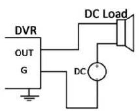
DC Load Connection Diagram

flowchart
graph TD
    A["DVR"] --> B["Relay alarm output"]
    B --> C["GND OUT 12V DC power"]
    C --> D["JQC 3FG Relay (10A 250VAC)"]
    D --> E["220V AC"]
    E --> F["AC Load"]
    B --> G["Alarm Out"]
    G --> D
    D --> H["Live Wire"]
    D --> I["Ground Wire"]
AC Load Connection Diagram
For DC loads, the outputs can be used with the jumpers in place, within the limit of 12V/1A safely.
To connect an AC load, jumpers should be removed (you must remove the jumper on the motherboard in the DVR). Do NOT connect high voltage to/through the DVR relays. Use an external relay for safety (as shown in the figure above).
There are 4 jumpers (JP1, JP2, JP3, and JP4) on the motherboard, each corresponding with one alarm output. By default, jumpers are connected. To connect an AC load, jumpers should be removed.
Example:
If you connect an AC load to the alarm output 3 of the DVR, then you must remove the jumper JP 3.
1.8 Alarm Connection
To connect alarm devices to the DVR:
- Disconnect pluggable block from the ALARM IN /ALARM OUT terminal block.
- Press and hold the orange part of the pluggable block; insert signal cables into slots and release the orange part. Ensure signal cables are in tight.
- Connect pluggable block back into terminal block.
1.9 RS-485 Connection
- Disconnect pluggable block from the RS-485 terminal block.
- Press and hold the orange part of the pluggable block; insert signal cables into slots and release the orange part. Ensure signal cables are in tight.
- Connect A+ on PTZ to D+ on terminal block and B- on controller to D- on terminal block. Fasten stop screws.
- Connect pluggable block back into terminal block.

To connect PTZ to the DVR:
- Disconnect pluggable block from the RS-485 terminal block.
- Press and hold the orange part of the pluggable block; insert signal cables into slots and release the orange part. Ensure signal cables are in tight.
- Connect A+ on PTZ to T+ on terminal block and B- on controller to T- on terminal block. Fasten stop screws.
- Connect pluggable block back into terminal block.
Make sure the DVR is grounded.
Chapter 2 Getting Started
2.1 Starting Up and Shutting Down the DVR
Purpose:
Proper startup and shutdown procedures are crucial to extending the life of the DVR.
Before you start:
Check that the voltage of and external power supply matches the DVR's requirement, and the ground connection is functioning properly.
Starting up the DVR
Steps:
- Check the power supply is plugged into the proper electrical outlet. It is HIGHLY recommended that an Uninterruptible Power Supply (UPS) be used in conjunction with the device.
- Turn on the power switch on the rear panel, and the Power indicator LED should turn on indicating that the unit has begun to start up.
- After startup, the Power indicator LED remains on.
Shutting down the DVR
Steps:
There are two proper ways to shut down the DVR. To shut down the DVR:
• OPTION 1: Standard shutdown
- Enter the Shutdown menu.
Menu > Shutdown

Figure 2.1 Shutdown Menu
- Select the Shutdown button.
- Click the Yes button.
- Turn off the power switch on the rear panel when the note appears.
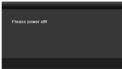
Figure 2.2 Shutdown Tips
- OPTION 2: By operating the front panel button (for EZHD-TRF series)
-
Press and hold the POWER button on the front panel for 3 seconds.
-
Enter the administrator's username and password in the dialog box for authentication.
- Click the Yes button.

- Do not press the POWER button again when the system is shutting down.
- The device remains standby mode after shutting down, and the POWER indicator turns red; you can turn on the device by pressing the POWER button on the remote control.
Rebooting the DVR
While in the Shutdown menu (Figure 2.1), you can also reboot the DVR.
Steps:
- Enter the Shutdown menu by clicking Menu > Shutdown.
- Click the Logout button to log out or the Reboot button to reboot the DVR.
2.2 Using the Wizard for Basic Configuration
By default, the Setup Wizard will start once the DVR has loaded, as shown in Figure 2.3.
Steps:
- Please select the system language in the drop-down list as desired

Figure 2.3 Language Selection
- The Setup Wizard can walk you through some important settings on the DVR. If you do not want to use the Setup Wizard at this time, click the Cancel button. You can also choose to use the Setup Wizard next time by leaving the "Start wizard when device starts?" checkbox marked.

Figure 2.4 Start Wizard Interface
- Click Next button on the Wizard window to display the Login window, as shown in Figure 2.5.

Figure 2.5 Login Window
- Enter the admin password. By default, the password is 12345.

It is highly recommended to change the default password right after the first login to avoid security issues.
- To change the admin password, check the New Admin Password checkbox. Enter the new password and confirm the password in the given fields.
- Click the Next button to enter the date and time settings window, as shown in Figure 2.6.

Figure 2.6 Date and Time Settings
- After the time settings, click Next button which will take you back to the General Network Setup Wizard window, as shown in Figure 2.7.
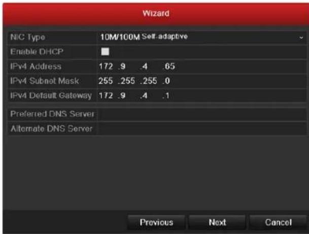
Figure 2.7 General Network Configuration

- Click Next button after you having configured the network parameters, which will take you to the Advanced Network Setup Wizard window, as shown in Figure 2.8.

Figure 2.8 Advanced Network Configuration
- Set the parameters of port No., Auto UPnP or DDNS if required.
- Click Next button after configuring the advanced network parameters, which will take you to the HDD Management window, shown in Figure 2.9.

Figure 2.9 HDD Management
- To initialize the HDD, click the Init button. Initialization will remove all the data saved in the HDD.
- Click Next button to enter the Record Settings window, as shown in Figure 2. 10.
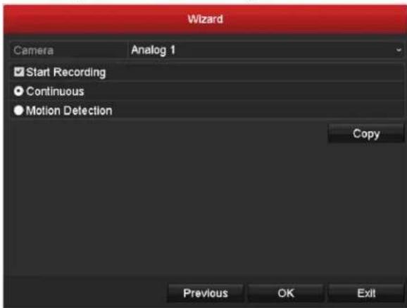
Figure 2.10 Record Settings
- Click Copy to copy the recording setting to other cameras.
- Click OK to save the settings and exit the wizard.
2.3 Adding/Connecting OMNI IP Cameras
2.3.1 Adding Online OMNI IP PnP Cameras
Purpose:
The main function of this feature is to connect a network cameras and view/record the video received from it. Before you can get a live view or record the video, you must add the network camera(s) to the DVR's connection list.
Before you start:
Ensure the network connection is valid and correct. For detailed checking and configuration of the network, please see Chapter 9.1, 9.3 and 9.4.

For an EZHD-TVL4 only one IP camera can be connected; for other EZHD-T models, up to IP cameras can be connected.
• OPTION 1:
Steps:
- Right-click the mouse when you in the live view mode to show the right-click menu.
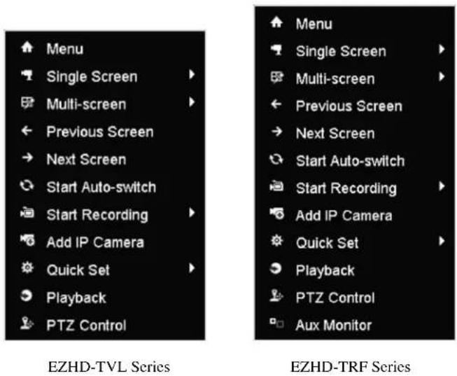
Figure 2.11 Right-click Menu
- Select Add IP Camera in the pop-up menu to enter the IP Camera Management interface.

Figure 2.12 Adding IP Camera Interface
- Online OMNI IP cameras on the same network segment will be displayed in the camera list. Click the 🧑 button to add the camera. Or you can click the Add All button to add all the detected online IP cameras.
Table 2.1 Explanation of the icons
| Icon | Explanation | Icon | Explanation |
| [05x4] | Edit basic parameters for the camera | Add the detected IP camera. | |
| [05y4] | The camera is connected. | The camera is disconnected; you can click the icon to get exception information for camera. | |
 | Delete the IP camera | Advanced settings of the camera. | |
| [H05X] | Update the IP camera |
- To add other IP cameras:
1) Click the Custom Adding button to pop up the Add IP Camera (Custom) interface.
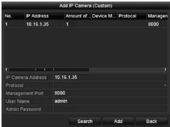
Figure 2.13 Add IP Camera (Custom) Interface
2) You can manually enter the IP address, protocol, management port, and other information for the IP camera to be added. Only OMNI IP Plug-and-Play cameras using the IPCAM protocol are supported at this time.
3) Click Add to add the camera.
• OPTION 2:
Steps:
- Enter the Camera Management interface.
Menu> Camera> Camera
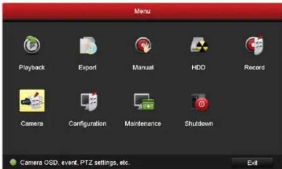
Figure 2.14 Main Menu
- Repeat the step 3 and 4 of OPTION 1 to add the camera.
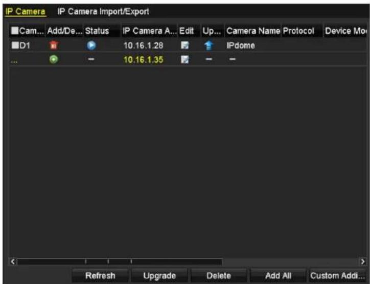
Figure 2. 15 IP Camera Management Interface
Table 2.2 Explanation of the icons
| Icon | Explanation | Icon | Explanation |
| Edit basic parameters for the camera | [4446] | Add the detected IP camera. | |
| The camera is connected; you can click the icon to get the live view from the camera.Delete the IP camera | [1024] | The camera is disconnected; you can click the icon to get exception information for camera.Advanced settings of the camera, | |
| Update the IP camera |
2.3.2 Editing the Connected IP Cameras and Configuring Customized Protocols
After adding the IP cameras, the basic information for the cameras displays in the OSD, and you can configure the basic settings for the IP cameras.
Steps:
- Click the icon to edit the parameters; you can edit the IP address, protocol (at this time only IPCAM is supported) and other parameters.
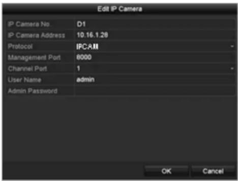
Figure 2.16 Edit the Parameters
Channel Port: If the connected device is an encoding device with multiple channels, you can choose the channel to connect by selecting the channel port No. in the dropdown list. At this time, only Channel 1 is supported.
- Click OK to save the settings and exit the editing interface.
To edit advanced parameters:
Steps:
- Drag the horizontal scroll bar to the right side and click the icon.
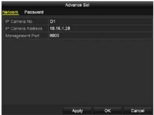
Figure 2.17 Network Configuration of the Camera
- You can edit the network information and the password for the camera.

Figure 2.18 Password Configuration of the Camera
- Click Apply to save the settings and click OK to exit the interface.
Chapter 3 Live View
3.1 Introduction to Live View
Live view shows you the video image from each camera in real time. The DVR will automatically enter Live View mode when powered on. It is also at the very top of the menu hierarchy, thus hitting the ESC many times (depending on which menu you're on) will bring you to the Live View mode.
Live View Icons
In the live view mode, there are icons at the top right of the window for each channel, showing the status of recording and alarms for the channel, so that you can know whether the channel is recording, or whether there are alarms as soon as possible.
Table 3.1 Description of Live View Icons
| Icons | Description |
| [4+057] | Alarm (video loss, tampering, motion detection or sensor alarm) |
| [4+057] | Record (manual record, schedule record, motion detection or alarm triggered record) |
| [8037] | Alarm & Record |
| [0566] | Event/Exception (motion detection, sensor alarm or exception information. For details, see Chapter 8.6 Handling Exceptions.) |
3.2 Operations in Live View Mode
In live view mode, there are many functions provided. The functions are listed below.
• Single Screen: show only one camera on the monitor.
• Multi-screen: show multiple cameras on the monitor simultaneously.
- Auto-switch: the camera or display is auto switched to the next camera or display. You must set the dwell time for each screen in the configuration menu before enabling the auto-switch. Menu>Configuration>Live View>Dwell Time.
- Start Recording: normal record and motion detection record are supported.
- Quick Set: select the output mode to Standard, Bright, Gentle or Vivid.
- Playback: play back the recorded videos for the current day.
- Aux/Main output switch: [for EZHD-TRF DVRs with CBVS aux monitor outputs] the DVR checks the connections of the output interfaces to define the main and auxiliary output interfaces. The priority level for the main and aux output is HDMI/VGA>CVBS. This means if the HDMI or VGA is used, it will be the default main output. If the HDMI/VGA is not used, the CVBS output will be the main output. See the table below. NOTE: The HDMI and VGA images displayed are identical on EZHD DVRs.
Table 3.2 Priorities of Interfaces for EZHD-TRF Models
| HDMI/VGA | CVBS | Main output | Auxiliary output | |
| 1 | HDMI/VGA | CVBS | ||
| 2 | × | CBVS | N/A | |
| 3 | CVBS | HDMI/VGA |
- means the interface is in use, × means the interface is out of use or the connection is invalid. The HDMI, VGA and CVBS can be used at the same time.
The choice of HDMI/VGA or CVBS for main output is made in the OSD menu. When the aux output is enabled, the main output cannot perform any operations, and you can do only basic operation in the live view mode using the Aux output.
3.2.1 Front Panel Operation
Table 3. 3 Front Panel Operation in Live View
| Functions | Front Panel Operation |
| Show single screen | Press the corresponding Alphanumeric button. E.g. Press 2 to display only the screen for channel 2. |
| Show multi-screen | Press the PREV button. |
| Manually switch screens | Next screen: right direction button.Previous screen: left direction button. |
| Auto-switch | Press Enter button. |
| Playback | Press Play button. |
3.2.2 Using the Mouse in Live View
Table 3.4 Mouse Operation in Live View
| Name | Description |
| Menu | Launch the system main menu by right clicking the mouse. |
| Single Screen | Switch to the single full screen by choosing a channel number from the dropdown list. |
| Multi-screen | Adjust the screen layout by choosing a split from the dropdown list. |
| Previous Screen | Switch to the previous screen. |
| Next Screen | Switch to the next screen. |
| Start/Stop Auto-switch | Enable/disable the auto-switching of the screens. The dwell time of the live view configuration must be set before using Start Auto-switch. The dwell time of the live view configuration must be set before using Start Auto-switch. |
| Start Recording | Start recording all channels, Normal Record and Motion Detection Recording are selectable from the dropdown list. |
| Add IP Camera | A shortcut to enter the IP camera management interface. |
| Quick Set | Output Mode is configurable with Standard, Bright, Gentle and Vivid options. |
| Playback | Enter the playback interface and start playing back the video from the selected channel immediately. |
| PTZ Control | A shortcut to enter the PTZ control interface for the selected camera. |
| Aux Monitor | Switch to the auxiliary output mode and the operation for the main output is disabled. [EZHD-TRF models only] f you enter Aux monitor mode and the Aux monitor is not connected, the mouse operation is disabled; you need to switch back to the Main output with the F1 button on front panel or VOIP/MON button on IR remote control and then press the Enter button. f you enter Aux monitor mode and the Aux monitor is not connected, the mouse operation is disabled; you need to switch back to the Main output with the F1 button on front panel or VOIP/MON button on IR remote control and then press the Enter button. |
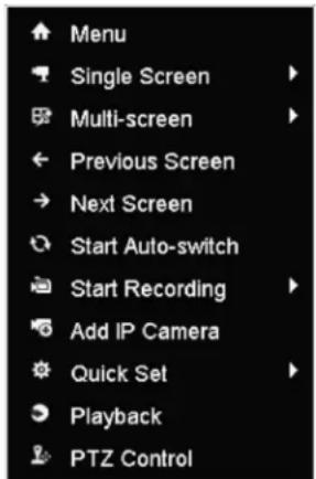

EZHD-TVL Series
EZHD-TRF Series
Figure 3.1 Right-click Menu
3.2.3 Using an Auxiliary Monitor [EZHD-TRF models]
Certain features of the Live View are also available while using an Aux monitor. These features include:
- Single Screen: Switch to a full screen display of the selected camera. Camera can be selected from a dropdown list.
- Multi-screen: Switch between different display layout options. Layout options can be selected from a dropdown list.
- Previous Screen: When displaying less than the maximum number of cameras in Live View, clicking this feature will switch to the previous set of displays.
- Next Screen: When displaying less than the maximum number of cameras in Live View, clicking this feature will switch to the next set of displays.
- Quick Set: Set the video output mode to Standard, Bright, Gentle or Vivid.
- Menu Output Mode: Select the menu output mode to HDMI/VGA, Main CVBS or Auto.
• PTZ Control: The shortcut to enter the PTZ control interface.
• Main Monitor: Enter Main operation mode.
![KT&C EZHD-TRF8 - Using an Auxiliary Monitor [EZHD-TRF models] - 1](/content/2026/05/995333/images/cc0f24200f1126169f14db229de4dd38873ac17c537cd7548ffbb6b72748e214.jpg)
In the live view mode of the main output monitor, the menu operation is not available while Aux output mode is enabled.
3.2.4 Main/Aux Output Switching [EZHD-TRF models]
When the HDMI/VGA output is configured as the main output, you can perform the following operation to switch to CVBS output as the main output.
Steps:
- Use the mouse wheel to double-click on the HDMI/VGA output screen, and the following message box pops up:
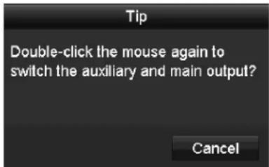
Figure 3.2 Switch Main and Aux Output
- Use the mouse wheel to double-click on the screen again to switch to the Aux output, or click Cancel to cancel the operation.
- Select the Menu Output Mode to Main CVBS from the right-click menu on the CVBS output monitor.
- On the pop-up message box, click Yes to restart the device to enable the CVBS output as the main output.

You can select the Menu Output Mode under Menu>Configuration>More Settings to Auto or HDMI/VGA and then restart the device to switch the main output back to HDMI/VGA output.
3.2.5 Quick Setting Toolbar in Live View Mode
On the screen of each channel, there is a quick setting toolbar which shows when you point the mouse to the bottom of the screen.

Figure 3.3 Quick Setting Toolbar
Table 3.5 Description of Quick Setting Toolbar Icons
| Icons | Description | Icons | Description | Icons | Description |
 | Enable/Disable Manual Record |  | Instant Playback |  | Mute/Audio on |
 | PTZ Control |  | Digital Zoom |  | Image Settings |
 | Close Live View |

Instant Playback only shows the recorded video from the last five minutes. If no recorded video is found, it means there is no video on the last five minutes.

Digital Zoom can zoom in the selected area to the full screen. Click and drag to draw and select the area to zoom in, as shown in
Figure 3.4.

natural_image
Highway scene with vehicles and shipping containers, residential buildings in background (no visible text or symbols)Figure 3.4 Digital Zoom

Image Settings icon can be selected to enter the Image Settings menu.
Four modes are selectable according to the real situation:
• Standard: for general lighting conditions (default).
- Indoor: the image is relatively smoother.
• Dim Light: the image is smoother than the other two modes.
• Outdoor: the image is relatively clearer and sharper. The degree of contrast and saturation is high.

Figure 3.5 Image Settings
You can adjust the image parameters, including brightness, contrast, saturation, hue, sharpness and de-noising. You can also click Default to restore the default settings and click Copy to copy the image settings to other analog cameras.
Refer to the Chapter 11.3 Configuring Video Parameters for details.
3.3 Channel-zero Encoding
Purpose:
Sometimes you need to get a remote view of many channels in real time from a web browser or the OMNI CMS (Client Management System) software, which may lead to streaming more bandwidth than desired. In order to decrease the bandwidth demand, channel-zero encoding is supported as an option.
Steps:
- Enter the Live View Settings interface.
Menu> Configuration> Live View
- Select the Channel-Zero Encoding tab.

Figure 3.6 Live View- Channel-Zero Encoding
- Check the checkbox after Enable Channel-Zero Encoding.
- Configure the Frame Rate, Max. Bitrate Mode and Max. Bitrate.
- Click the Apply button to activate the settings.
After you set the Channel-Zero encoding, you can get a view in the remote client or web browser of 16 channels in one screen with a controllable maximum bitrate for that multiplex view.
3.4 Adjusting Live View Settings
Purpose:
Live View settings can be customized to suit different needs. You can configure the output interface, dwell time for each screen to be shown, mute or enable audio, choose the location for each camera, etc.
Steps:
- Enter the Live View Settings interface.
Menu> Configuration> Live View

Figure 3.7 Live View-General
The settings available in this menu include:
- Video Output Interface: Designates the output for main monitor menus. Choices are HDMI/VGA and CVBS (for EZHD-TRF models only).
• Live View Mode: Designates the display screen layout to be used during Live View.
• Dwell Time: The time in seconds to dwell between switching of channels when enabling auto-switch in Live View. - Enable Audio Output: Enables/disables audio output for the selected camera in the live view mode.
-
Event Output: Designates the output to show event video; if available, you can select a different video output interface from the Video Output Interface when an event occurs.
• Full Screen Monitoring Dwell Time: The time in seconds to show alarm event screen before reverting to original view. -
Set the camera order.
1) Select View tab.

Figure 3.8 Live View- Camera Order
2) Click a window to select it, and then double-click a camera name in the camera list you would like to display. Setting an 'X' means the window will not display any camera.
3) You can also click 📄 to start live view of all channels in order and click 📄 to stop live view of all channels. Click 📄 or 📋 to go to the previous or next page.
4) Click the Apply button.
3.5 Manual Video Quality Diagnostics
Purpose:
The video quality of the analog channels can be checked manually and you can view the diagnostic results in a list.
Steps:
- Enter the Manual Video Quality Diagnostics interface.
Menu> Manual >Manual Video Quality Diagnostics

Figure 3.9 Video Quality Diagnostics
-
Check the checkboxes to select the channels for diagnostics.
-
Click the button Diagnose, and the results will be displayed on a list. You can view the video status and diagnostics time of the selected channels.

Figure 3.10 Diagnostics Result

- Connect the camera to the device for the video quality diagnostics.
● Three exception types can be diagnosed: Blurred Image, Abnormal Brightness and Color Cast.
3.6 User Logout
Purpose:
After logging out, the monitor turns to the live view mode and if you want to do some operation, you need to enter user name and password to log in again.
Steps:
- Enter the Shutdown menu.
Menu>Shutdown

Figure 3.11 Shutdown
- Click Logout.

After you have logged out the system, menu operation on the screen is invalid. It is required a user name and password to login the system.
Chapter 4 PTZ Controls
4.1 Configuring PTZ Settings
Purpose:
Follow this procedure to set the parameters for PTZs. Configuring PTZ parameters should be done before you attempt to control the PTZ camera.
Steps:
- Enter the PTZ Settings interface.
Menu >Camera> PTZ

Figure 4.1 PTZ Settings
- Choose the camera for PTZ setting in the Camera dropdown list.
- Click the RS-485 Settings button to set the RS-485 parameters.

Figure 4.2 PTZ-General
- Enter the parameters of the PTZ camera.

All the parameters should be set to match the PTZ camera parameter requirements.

When a KT&C Up-the-Cable [Coaxitron] capable camera/PTZ connected, you can select the PTZ protocol to be HDCAM-C. Make sure the protocol selected here is supported by the connected camera/PTZ.
When the Coaxitron protocol is selected, all the other parameters like the baud rate, data bit, stop bit, parity and flow control are not configurable.
- Click Apply button to save the settings.
NOTE: To access the OSD menu on KT&C Up-the-Cable compatible cameras use the "IRIS+" [iris open] function as the "MENU" or "ENTER" function. Otherwise, the OSD menus can be navigated via the up/down direction buttons, and one can scroll through selection choices by using the left/right direction buttons. The direction button roles may change in various OSD sub-menus. Refer to the OSD prompts and/or the camera documentation for details.
4.2 Setting PTZ Presets, Patrols & Patterns
Before you start:
Please make sure that the presets, patrols and patterns should be supported by PTZ protocols.
4.2.1 Customizing Presets
Purpose:
Follow the steps to set the Preset location which you want the PTZ camera to point to when an event takes place.
Steps:
- Enter the PTZ Control interface.
Menu>Camera>PTZ

Figure 4.3 PTZ Settings
- Use the directional button to wheel the camera to the location where you want to set preset; and the zoom and focus operations can be recorded in the preset as well.
- Enter the preset No. (1\~255) in the preset text field, and click the Set button to link the location to the preset.
Repeat the steps2-3 to save more presets.
You can click the Clear button to clear the location information of the preset, or click the Clear All button to clear the location information of all the presets.
4.2.2 Calling Presets
Purpose:
This feature enables the camera to point to a specified position when an event takes place.
Steps:
- Click the button PTZ in the lower-right corner of the PTZ setting interface;
Or press the PTZ button on the front panel or click the PTZ Control icon in the quick setting bar, or select the PTZ option in the right-click menu to show the PTZ control panel.
-
Choose Camera in the dropdown list.
-
Click the ▶ button to show the general settings of the PTZ control.

Figure 4.4 PTZ Panel - General
-
Click to enter the preset No. in the corresponding text field.
-
Click the Call Preset button to call it.

When a Coaxitron camera/dome connected and the PTZ protocol is selected to HDCAM-C (Coaxitron), you can call preset 95 to enter the menu of the connected Coaxitron camera/dome. Use the directional buttons on the PTZ control panel to operate the menu.
4.2.3 Customizing Patrols
Purpose:
Patrols can be set to move the PTZ to different key points and have it stay there for a set duration before moving on to the next key point. The key points are corresponding to the presets. The presets can be set following the steps above in Customizing Presets.
Steps:
- Enter the PTZ Control interface.
Menu>Camera>PTZ

Figure 4.5 PTZ Settings
- Select patrol No. in the drop-down list of patrol.
- Click the Set button to add key points for the patrol.

Figure 4.6 Key point Configuration
- Configure key point parameters, such as the key point No., duration of staying for one key point and speed of patrol. The key point is corresponding to the preset. The Key Point No. determines the order at which the PTZ will follow while cycling through the patrol. The Duration refers to the time span to stay at the corresponding key point. The Speed defines the speed at which the PTZ will move from one key point to the next.
- Click the Add button to add the next key point to the patrol, or you can click the OK button to save the key point to the patrol. You can delete all the key points by clicking the Clear button for the selected patrol, or click the Clear All button to delete all the key pints for all patrols.
4.2.4 Calling Patrols
Purpose:
Calling a patrol makes the PTZ to move according the predefined patrol path.
Steps:
- Click the button PTZ in the lower-right corner of the PTZ setting interface;
Or press the PTZ button on the front panel or click the PTZ Control icon in the quick setting bar, or select the PTZ option in the right-click menu to show the PTZ control panel. - Click the ▶ button to show the general settings of the PTZ control.

Figure 4.7 PTZ Panel - General
- Select a patrol in the dropdown list and click the Call Patrol button to call it.
- You can click the Stop Patrol button to stop calling it.
4.2.5 Customizing Patterns
Purpose:
Patterns can be set by recording the movement of the PTZ. You can call the pattern to make the PTZ movement according to the predefined path.
Steps:
- Enter the PTZ Control interface.
Menu > Camera > PTZ

Figure 4.8 PTZ Settings
- Choose pattern number in the dropdown list.
- Click the Start button and click corresponding buttons in the control panel to move the PTZ camera, and click the Stop button to stop it.
The movement of the PTZ is recorded as the pattern.
4.2.6 Calling Patterns
Purpose:
Follow the procedure to move the PTZ camera according to the predefined patterns.
Steps:
- Click the button PTZ in the lower-right corner of the PTZ setting interface;
Or press the PTZ button on the front panel or click the PTZ Control icon in the quick setting bar, or select the PTZ option in the right-click menu to show the PTZ control panel.
- Click the ▶ button to show the general settings of the PTZ control.

Figure 4.9 PTZ Panel - General
- Click the Call Pattern button to call it.
- Click the Stop Pattern button to stop calling it.
4.2.7 Customizing Linear Scan Limit
Purpose:
The Linear Scan can be enabled to trigger the scan in the horizontal direction in the predefined range.

This function is supported by some certain models.
Steps:
- Enter the PTZ Control interface.
Menu > Camera > PTZ

Figure 4. 10 PTZ Settings
- Use the directional button to wheel the camera to the location where you want to set the limit, and click the Left Limit or Right Limit button to link the location to the corresponding limit.

The speed dome starts linear scan from the left limit to the right limit, and you must set the left limit on the left side of the right limit, as well the angle from the left limit to the right limit should be no more than 180^ .
4.2.8 Calling Linear Scan
Purpose:
Follow the procedure to call the linear scan in the predefined scan range.
Steps:
- Click the button PTZ in the lower-right corner of the PTZ setting interface;
Or press the PTZ button on the front panel or click the PTZ Control icon 📄 in the quick setting bar to enter the PTZ setting menu in live view mode.
- Click the D button to show the one-touch function of the PTZ control.

Figure 4.11 PTZ Panel - One-touch
- Click Linear Scan button to start the linear scan and click the Linear Scan button again to stop it.
You can click the Restore button to clear the defined left limit and right limit data and the dome needs to reboot to make settings take effect.
4.2.9 One-touch Park
Purpose:
For some certain model of the speed dome, it can be configured to start a predefined park action (scan, preset, patrol and etc.) automatically after a period of inactivity (park time).
Steps:
- Click the button PTZ in the lower-right corner of the PTZ setting interface;
Or press the PTZ button on the front panel or click the PTZ Control icon in the quick setting bar to enter the PTZ setting menu in live view mode.
- Click the ▶ button to show the one-touch function of the PTZ control.

Figure 4. 12 PTZ Panel - One-touch
- There are 3 one-touch park types selectable, click the corresponding button to activate the park action.
Park (Quick Patrol): The dome starts patrol from the predefined preset 1 to preset 32 in order after the park time. The undefined preset will be skipped.
Park (Patrol 1): The dome starts move according to the predefined patrol 1 path after the park time.
Park (Preset 1): The dome moves to the predefined preset 1 location after the park time.

The park time can only be set through the speed dome configuration interface, by default the value is 5s.
- Click the button again to inactivate it.
4.3 PTZ Control Panel
To enter the PTZ control panel, there are two ways supported.
OPTION 1:
In the PTZ settings interface, click the PTZ button on the lower-right corner which is next to the Back button.
OPTION 2:
In the Live View mode, you can press the PTZ Control button on the front panel or on the remote control, or choose the PTZ Control icon

or select the PTZ option in the right-click menu.
Click the Configuration button on the control panel, and you can enter the PTZ Settings interface.

In PTZ control mode, the PTZ panel will be displayed when a mouse is connected with the device. If no mouse is connected, the

icon appears in the lower-left corner of the window, indicating that this camera is in PTZ control mode.
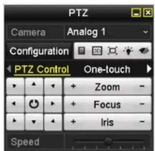


Figure 4.13 PTZ Panel
Table 4.1 Description of the PTZ panel icons
| Icon | Description | Icon | Description | Icon | Description |
 | Direction button and the auto-cycle button | [56SW] | Zoom+, Focus+, Iris+ | [1234] | Zoom-, Focus-, Iris- |
| [7070] | The speed of the PTZ movement | [WT40] | Light on/off | [4220] | Wiper on/off |
| [7322] | 3D-Zoom |  | Image Centralization | [527Y] | Menu |
| [7071] | Switch to the PTZ control interface | [3551] | Switch to the one-touch control interface | [6000] | Switch to the general settings interface |
| [7405] | Previous item | [5962] | Next item | [5C52] | Start pattern / patrol |
| [4004] | Stop the patrol / pattern movement | [2640] | Exit | [8000] | Minimize windows |
Chapter 5 Recording Settings
5.1 Configuring Encoding Parameters
Before you start:
- Make sure that the HDD has already been installed. If not, please install a HDD and initialize it. (Menu>HDD>General)

Figure 5.1 HDD- General
- Click Advance to check the storage mode of the HDD.
1) If the HDD mode is Quota, please set the maximum record capacity. For detailed information, see Chapter 10.5 Configuring Quota Mode.
2) If the HDD mode is Group, you should set up an HDD group. For detailed information, see Chapter 5.8 Configuring HDD Group for Recording.
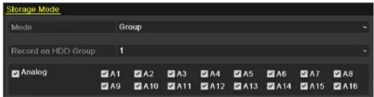
Figure 5.2 HDD-Advanced
Steps:
- Enter the Record settings interface to configure the encoding parameters:
Menu>Record>Encoding

Figure 5.3 Record Encoding
2. Set the encoding parameters for recording.
1) Select the Record tab to configure.
2) Select a camera number in the camera dropdown list.
You can configure the stream type, the resolution, the video quality and other parameters on demand for Main Stream (Continuous) and Main Stream (Event) respectively.
The Input Resolution of camera connected will be displayed in the live view for 5 seconds when a camera is connected, or the DVR is powered on. The input resolution includes the resolution and frame rate of the camera, c.g. 1080p30.
3) You can configure the additional parameters, including pre-record, post-record time, expired time, redundant record (this option is only available when the HDD mode is Group) and whether you want to record audio.
- Pre-record: The time you set to record before the scheduled time or event. For example, when an alarm triggered the recording at 10:00, if you set the pre-record time as 5 seconds, the camera records it at 9:59:55.
- Post-record: The time you set to record after the event or the scheduled time. For example, when an alarm triggered the recording ends at 11:00, if you set the post-record time as 5 seconds, it records till 11:00:05.
- Expired Time: The expired time is the longest time for a record file to be kept in the HDD; if the time is reached, the file will be deleted. You can set the expired time to 0, and then files will not be deleted. The actual retention time for files should be determined by the capacity of the HDD.
- Redundant Record: The redundant record is to decide whether you want the camera to save the record files in the redundant HDD. You must configure the redundant HDD in HDD settings. For detailed information, see Chapter 5.7 Configuring Redundant Recording.
- Record Audio: Check the checkbox of Record Audio to record the sound, otherwise record the image without sound.
- Video Stream: Main stream and sub-stream are selectable for recording. When you select sub-stream, you can record for a longer time with the same storage space.
- Enable 960 Mode: The option is supported for CVBS analog cameras. Enabling the 960 mode allows WDI resolution recording for the main stream; otherwise, the CVBS resolution supports up to only 4CIF. This option does not appear for TVI cameras, since the WDI resolution record option is available at all times for TVI cameras.
4) Click Apply to save the settings.
5) You can copy the settings to other channels by clicking Copy, if the settings can also be used for other cameras (native resolution must match).

You can copy the same settings to the cameras with same signal type, e.g., channel No. 1-3 are connected to TVI cameras, and channel No.4 connects to an analog camera, and then the settings of channel No. 1 can be only copied to channel 2 and 3.

Figure 5.4 Copy Camera Settings
- Set encoding parameters for sub-stream.
1) Select the Substream tab.

Figure 5.5 Sub-stream Encoding
2) Select a camera in the camera dropdown list.
3) Configure the parameters.
4) Click Apply to save the settings.
5) (Optional) If the parameters can also be used to other cameras, click Copy to copy the settings to other channels.
5.2 Configuring Record Schedule
Purpose:
Set the record schedule, and then the camera will automatically start/stop recording according to the configured schedule.
Steps:
- Enter the Record Schedule interface.
Menu> Record> Schedule
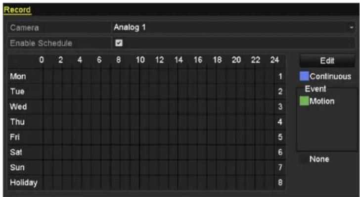
EZHD-TVL

EZHD-TRF
Figure 5.6 Record Schedule
- Choose the camera you want to configure in the Camera dropdown list.
- Check the checkbox of Enable Schedule.
- Configure the record schedule.
Edit the schedule
1) Click Edit.
2) In the message box, you can choose the day to which you want to set schedule.
3) To schedule an all-day recording, check the checkbox after the All Day item.

Figure 5.7 Edit Schedule- All Day
4) To arrange other schedule, leave the All Day checkbox blank and set the Start/End time.

Figure 5.8 Edit Schedule- Set Time Period

Up to 8 periods can be configured for each day. And the time periods cannot be overlapped with each other.
Repeat the above steps 1-4 to schedule recording for other days in the week. If the same schedule will also be used on other days, click Copy.
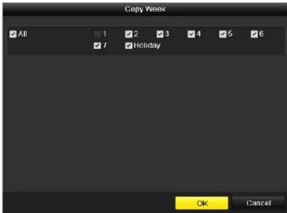
Figure 5.9 Copy Schedule to Other Days

The Holiday option is available when you enable the holiday schedule in Holiday settings. See Chapter 5.6 Configuring Holiday Record.
5) Click OK to save setting and back to upper level menu.
Draw the schedule
1) Click on the color icon to select a record type in the event list on the right-side of the interface.

Figure 5.10 Draw the Schedule
Descriptions of the color icons are shown in the figure below.
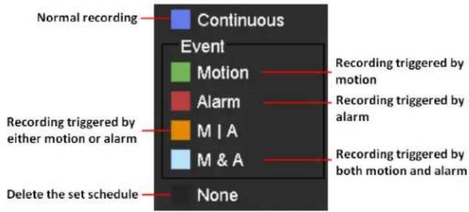
Figure 5.11 Descriptions of the Color Icons
2) Click and drag the mouse on the schedule.
3) Click on the other area except for the schedule table to finish and exit the drawing.
You can repeat step 4 to set schedule for other channels. If the settings can also be used to other channels, click Copy, and then choose the channel to which you want to copy.
- Click Apply in the Record Schedule interface to save the settings.
5.3 Configuring Motion Detection Record
Purpose:
Follow the steps to set the motion detection parameters. In the live view mode, once a motion detection event takes place, the DVR can analyze it and do many actions to handle it. Enabling motion detection function can trigger certain channels to start recording, or trigger full screen monitoring, audio warning, notifying the surveillance center, sending email and so on.
Steps:
- Enter the Motion Detection interface.
Menu>Camera>Motion

Figure 5.12 Motion Detection
- Configure Motion Detection:
1) Choose camera you want to configure.
2) Check the checkbox after Enable Motion Detection.
3) Drag and draw the area for motion detection by mouse. If you want to set the motion detection for all the area in view of the camera, click Full Screen. To clear the motion detection area, click Clear.

Figure 5.13 Motion Detection-Mask
4) Click Handling, and the message box for channel information pops up.
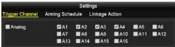
Figure 5.14 Motion Detection Settings
5) Select the channels which you want the motion detection event to trigger recording.
6) Click Apply to save the settings.
7) Click OK to back to the upper level menu.
8) Exit the Motion Detection menu.
3. Configure the schedule.
Please refer to the step 4 of Chapter 5.2 Configuring Record Schedule, where you may choose Motion as the record type.
5.4 Configuring Alarm Triggered Record

The EZHD-TVL4/8/16 do not have external alarm inputs nor outputs.
Purpose:
Follow the procedure to configure alarm triggered recording.
Steps:
- Enter the Alarm setting interface.
Menu> Configuration> Alarm

Figure 5.15 Alarm Settings
- Click the Alarm Input tab.
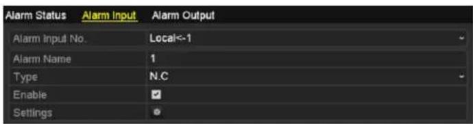
Figure 5.16 Alarm Settings- Alarm Input
1) Select Alarm Input number and configure alarm parameters.
2) Choose N.O (normally open) or N.C (normally closed) for alarm type.
3) Check the checkbox of Setting.
4) Click the button.
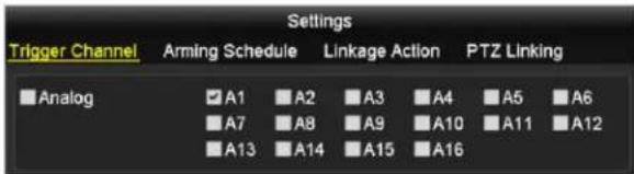
Figure 5.17 Alarm Handling
5) Choose the alarm triggered recording channel.
6) Check the checkbox √ to select channel.
7) Click Apply to save settings.
8) Click OK to back to the upper level menu.
Repeat the above steps to configure other alarm input parameters.
If the setting can also be applied to other alarm inputs, click Copy and choose the alarm input number.

Figure 5.18 Copy Alarm Input
3. Configure the schedule.
Please refer to the step 4 of Chapter 5.2 Configuring Record Schedule, where you may choose Alarm as the record type.
5.5 Manual Record
Purpose:
Follow the steps to set parameters for the manual record. Using manual record, you don't need to set a schedule for recording.
Steps:
- Enter the Manual settings interface.
Menu> Manual

Figure 5.19 Manual Record
- Enable manual record.
Click the status icon ON before camera number to change it to ON Or click the status icon ON of Analog to enable manual record of all channels.
- Disable manual record.
Click the status icon ON change it to . Or click the status icon ON of Analog to disable manual record of all channels.

After rebooting all the manual recordings enabled are canceled, so sechuled recording is highly recommended.
5.6 Configuring Holiday Record
Purpose:
Follow the steps to configure the record schedule on holiday for that year. You may want to have different plan for recording on holiday.
Steps:
- Enter the Record setting interface.
Menu>Record
- Choose Holiday on the left bar.

Figure 5. 20 Holiday Settings
- Enable Edit Holiday schedule.
1) Click to enter the Edit interface.

Figure 5.21 Edit Holiday Settings
2) Check the checkbox of Enable.
3) Select Mode from the dropdown list.
There are three different modes for the date format to configure holiday schedule. By Month, By Week, and By Month are selectable.
4) Set the start and end date.
5) Click Apply to save settings.
6) Click OK to exit the Edit interface.
- Configure the record schedule.
Please refer to the Chapter 5.2 Configuring Record Schedule, while you may choose Holiday in the Schedule dropdown list, or you can draw the schedule on the timeline of Holiday. See the two figures below.

Figure 5.22 Edit Schedule- Holiday

Figure 5.23 Draw Schedule-Holiday

Up to 8 periods can be configured for each day. And the time periods cannot be overlapped each other.
In the time table of the channel, both holiday schedule and normal day schedule are displayed.
Repeat the above step 4 to set Holiday schedule for other channel. If the holiday schedule can also be used to other channels, click Copy and choose the channel you want to apply the settings.
5.7 Configuring Redundant Recording [EZHD-TRF]
Purpose:
Enabling redundant recording, which means saving the record files not only in the R/W HDD but also in the redundant HDD, will effectively enhance the data safety and reliability.
Before you start:
Multiple HDs are required. You must set the Storage mode in the HDD advanced settings to Group before you set the HDD property to Redundant. For detailed information, please refer to Chapter 10.4 Managing HDD Group. There should be at least another HDD which is in Read/Write status.
Steps:
- Enter HDD Information interface.
Menu> HDD

Figure 5. 24 HDD General
- Select the HDD and click to enter the Local HDD Settings interface.
1) Set the HDD property to Redundant.

Figure 5.25 HDD General-Editing
2) Click Apply to save the settings.
3) Click OK to back to the upper level menu.
- Enter the Record setting interface.
Menu> Record> Encoding
1) Select the Record tab.
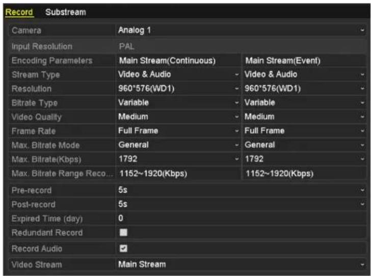
Figure 5.26 Encoding Parameters
2) Select Camera you want to configure.
3) Check the checkbox of Redundant Record.
4) Click Apply to save settings.
If the encoding parameters can also be used to other channels, click Copy and choose the channel you want to apply the settings.
5.8 Configuring HDD Group for Recording
Purpose:
You can group the HDDs and save the record files in certain HDD group.
Steps:
- Enter HDD setting interface.
Menu>HDD>Advanced
- Select Advanced on the left bar.
Check whether the storage mode of the HDD is Group. If not, set it to Group. For detailed information, please refer to Chapter 10.4 Managing HDD Group.
- Select General in the left bar.
Click to enter editing interface.
- Configuring HDD group.
1) Choose a group number for the HDD group.
2) Click Apply to save your settings.
3) Click OK to back to the upper level menu.
Repeat the above steps to configure more HDD groups.
- Choose the Channels which you want to save the record files in the HDD group.
1) Select Advanced on the left bar.

Figure 5.27 HDD Advanced
2) Choose Group number in the dropdown list of Record on HDD Group
3) Check the channels you want to save in this group.
4) Click Apply to save settings.

After you have configured the HDD groups, you can configure the Recording settings following the procedure provided in Chapter 5.2-5.7.
5.9 File Protection
Purpose:
You can lock the recorded files or set the HDD property to Read-only to protect the record files from being overwritten.
Protect file by locking the record files
Steps:
- Enter Playback setting interface.
Menu> Export
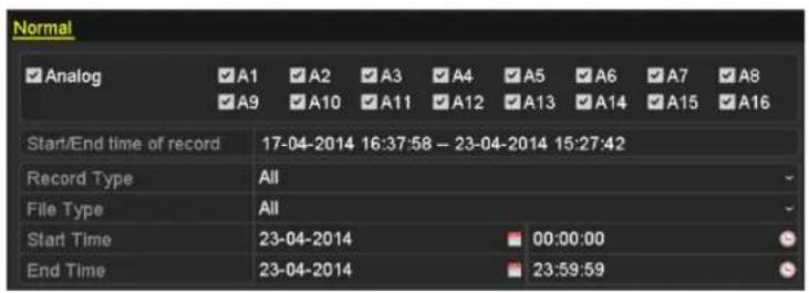
Figure 5.28 Export
- Select the channels you want to investigate by checking the checkbox to √.
- Configure the record type, file type, start time and end time.
- Click Search to show the results.

Figure 5.29 Export- Search Result
- Protect the record files.
1) Find the record files you want to protect, and then click the icon which will turn to indicating that the file is locked.

The record files of which the recording is still not completed cannot be locked.
2) Click 🔍 to change it to 🔍 to unlock the file and the file is not protected.
Protect file by setting HDD property to Read-only
Before you start:
To edit HDD property, you need to set the storage mode of the HDD to Group. See Chapter 10.4 Managing HDD Group.
Steps:
- Enter HDD setting interface.
Menu> HDD

Figure 5. 30 HDD General
- Click ☐ to edit the HDD you want to protect.

Figure 5. 31 HDD General- Editing
-
Set the HDD to Read-only.
-
Click OK to save settings and back to the upper level menu.

- You cannot save any files in a Read-only HDD. If you want to save files in the HDD, change the property to R/W.
- If there is only one HDD and is set to Read-only, the DVR cannot record any files. Only live view mode is available.
- If you set the HDD to Read-only when the DVR is saving files in it, then the file will be saved in next R/W HDD. If there is only one HDD, the recording will be stopped.
Chapter 6 Playback
6.1 Playing Back Record Files
6.1.1 Playing Back by Channel
Purpose:
Play back the recorded video files of a specific channel in the live view mode. Channel switch is supported.
- OPTION 1
Choose a channel in live view mode using the mouse and click the

button in the quick setting toolbar.

Only record files recorded during the last five minutes on this channel will be played back.

natural_image
Four-panel composite image showing a multi-lane highway with vehicles and trucks, no visible text or symbols.Figure 6.1 Instant Playback Interface
- OPTION 2
Steps:
- Enter the Playback interface.
Mouse: right click a channel in live view mode and select Playback from the menu, as shown in Figure 6.2.
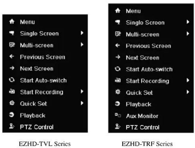
Figure 6.2 Right-click Menu under Live View
Front Panel: press PLAY button to play back recording files of the channel under single-screen live view mode.
Under multi-screen live view mode, the recorded files of the top-left channel will be played back.

Pressing numerical buttons will switch playback to the corresponding camera during playback process.
2. Playback management.
The toolbar in the bottom part of Playback interface can be used to control playing progress, as shown in Figure 6.3.
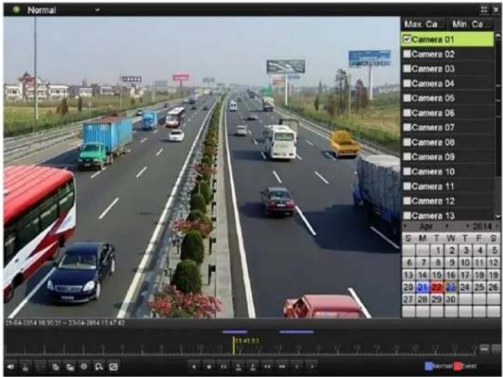
Figure 6.3 Playback Interface
Click the channel(s) if you want to switch playback to another channel or execute simultaneous playback of multiple channels.

Figure 6.4 Toolbar of Playback
Table 6.1 Detailed Explanation of Playback Toolbar
| Button | Operation | Button | Operation | Button | Operation |
 | Audio on/ Mute |  | Start/Stop clipping | [3A3S] | Save clip(s) |
| [T603] | Add default tag | [84KS] | Add customized tag | [2XHS] | Tag management |
 | Digital Zoom | [W226] | Smart Search |  | Pause / Reverse play/ Single-frame reverse play |
 | Stop | [XXKB] | Pause play/ Play/ Single-frame play | [T7AXW] | 30s reverse |
| [7ABW] | 30s forward |  | Speed down | [YHBW] | Speed up |
| [027W] | Previous day | [TO8T] | Next day | [BC5H] | Scaling up/down the time line |
 | Full Screen |  | Exit |  | Video type |
| Process bar | Video type bar |

● The 21-04-2014 16:35:31 -- 23-04-2014 15:47:42 indicates the start time and end time of the record files.
- represents normal recording (manual or schedule); - represents event recording (motion, alarm, motion | alarm, motion & alarm).
● Playback progress bar: use the mouse to click any point of the progress bar to locate special frames.
6.1.2 Playing Back by Time
Purpose:
Play back video files recorded in specified time duration. Multi-channel simultaneous playback and channel switch are supported.
Steps:
- Enter playback interface.
Menu>Playback
- Check the checkbox of channel(s) in the channel list and then double-click to select a date on the calendar.

Figure 6.5 Playback Calendar

If there are record files for that camera in that day, in the calendar, the icon for that day is displayed as 9. Otherwise it is displayed as 9
In the Playback interface:
The toolbar in the bottom part of Playback interface can be used to control playing process, as shown in Figure 6. 6.

Figure 6. 6 Interface of Playback by Time

Figure 6.7 Toolbar of Playback by Time
Table 6.2 Detailed Explanation of Playback Toolbar
| Button | Operation | Button | Operation | Button | Operation |
| Audio on/ Mute | Start/Stop clipping | Save clip(s) | |||
| Add default tag | Add customized tag | Tag management | |||
| Digital Zoom | Smart Search | Pause / Reverse play/ | |||
| Single-frame reverse play | |||||
| [7706] | Stop | [HXBZ] | Pause play/ Play/ Single-frame play |  | 30s reverse |
| [DOCK] | 30s forward | [2TDW] | Speed down |  | Speed up |
| [2674] | Previous day | [2H73] | Next day | [06KC] | Scaling up/down the time line |
| [XSDW] | Full Screen | [8008] | Exit | [2YYS] | Video type |
| Process bar | Video type bar |

● The 21-04-2014 16:35:31 - 23-04-2014 15:47:42 indicates the start time and end time of the record files.
- represents normal recording (manual or schedule); - represents event recording (motion, alarm, motion | alarm, motion & alarm).
- Playback progress bar: use the mouse to click any point of the progress bar to locate special frames.
6.1.3 Playing Back by Event Search
Purpose:
Play back recording files on one or several channels searched out by restricting event type (e.g. alarm input and motion detection).
Steps:
- Enter the Playback interface.
Menu > Playback - Select the Event in the drop-down list on the top-left side.
- Select Alarm Input or Motion as the event type, edit the Start time and End time.

Here we take the playback by motion as the example.

Figure 6.8 Motion Search Interface
- Click Search button to get the search result information. You may refer to the right-side bar for the result.
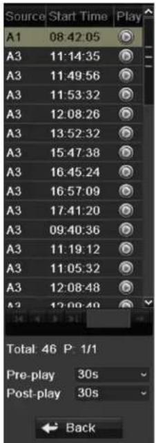
Figure 6.9 Search Result Bar
- Click 🎨 button to play back the file.
You can click the Back button to back to the search interface.

Pre-play and post-play can be configured.
- (Optional) If multiple channels are triggered recording by the alarm input, clicking the button will pop up a synchrononouse
playback channel selection window. Select channel(s) you want to play and click the OK button.
7. Playback management.
The toolbar in the bottom part of Playback interface can be used to control playing process.

Figure 6. 10 Interface of Playback by Event

Figure 6.11 Toolbar of Playback by Event
Table 6.3 Detailed Explanation of Playback-by-event Toolbar
| Button | Operation | Button | Operation | Button | Operation |
 | Audio on/ Mute | Start/Stop clipping | Save clip(s) | ||
| [007] | Add default tag | Add customized tag | Tag management | ||
| [47K2] | Digital Zoom | Smart Search(Not supported) | Pause / Reverse play/Single-frame reverse play | ||
 | Stop | Pause play/ Play/Single-frame play | 30s reverse | ||
| [003C] | 30s forward | Speed down | Speed up | ||
| [2Y2Y] | Previous day | Next day | Scaling up/down the time line | ||
| [GT60] | Full Screen | Exit | Video type | ||
| Process bar | Video type bar |

- represents normal recording (manual or schedule); - represents event recording (motion, alarm, motion | alarm, motion & alarm).
- Playback progress bar: use the mouse to click any point of the progress bar to locate special frames.
6.1.4 Playing Back by Tag
Purpose:
Video tag allows you to record related information like people and location of a certain time point during playback. You are also allowed to use video tag(s) to search for record files and position time point.
Before playing back by tag:
- Enter Playback interface.
Menu>Playback
- Search and play back the record file(s). Refer to Chapter 6.1.1 Playing Back by Channel for the detailed information about searching and playback of the record files.

Figure 6.12 Interface of Playback by Time
Click button to add default tag. Click button to add customized tag and input tag name.

Max. 64 tags can be added to a single video file.
- Tag management.
Click 📄 ton to check, edit and delete tag(s).
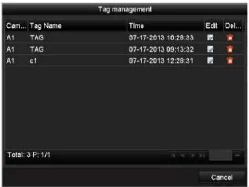
Figure 6.13 Tag Management Interface
Steps:
-
Select the Tag from the drop-down list in the Playback interface.
-
Choose channels, edit start time and end time, and then click Search to enter Search Result interface.

You can enter keyword in the textbox Keyword to search the tag on your command.

Figure 6. 14 Video Search by Tag
- Click button to play back the file.
You can click the Back button to back to the search interface.

Pre-play and post-play can be configured.
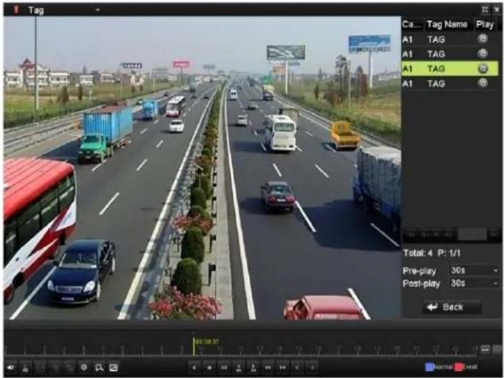
Figure 6.15 Interface of Playback by Tag

Figure 6.16 Toolbar of Playback by Tag
Table 6.4 Detailed Explanation of Playback-by-tag Toolbar
| Button | Operation | Button | Operation | Button | Operation |
| Audio on/ Mute | Start/Stop clipping | Save clip(s) | |||
| Add default tag | Add customized tag | Tag management | |||
| Digital Zoom | Smart Search | Pause / Reverse play/ Single-frame reverse play | |||
| Stop | Pause play/ Play/ Single-frame play | 30s reverse | |||
| 30s forward | Speed down | Speed up | |||
| Previous day | Next day | Scaling up/down the time line | |||
| Full Screen | Exit | Video type | |||
| Process bar | Video type bar |

- represents normal recording (manual or schedule); - represents event recording (motion, alarm, motion | alarm, motion &
alarm).
● Playback progress bar: use the mouse to click any point of the progress bar to locate special frames.
6.1.5 Smart Playback
Purpose:
The smart playback function provides an easy way to get through the less effective information. When you select the smart playback mode, the system will analyze the video with motion, mark it with green color and play it in the normal speed while the video without motion will be played in the 8-time speed.
Steps:
- Enter Playback interface.
Menu>Playback
- Select the Smart in the drop-down list on the top-left side.
- Select a date in the calendar and select a camera in the camera list.
- Click the button to play.
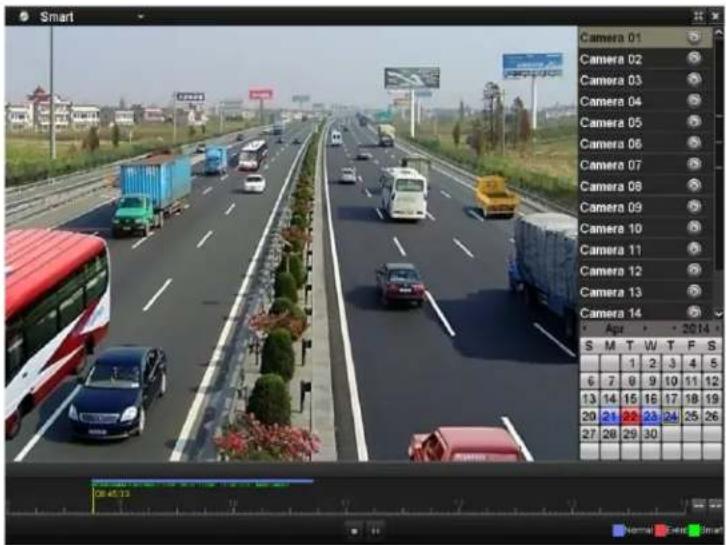
Figure 6.17 Smart Playback Interface
Table 6.5 Detailed Explanation of Smart Playback Toolbar
| Button | Operation | Button | Operation | Button | Operation |
| [0CT8] | Stop | [0x7C] | Pause play/Play | [0x6C] | Scalingup/down thetime line |
 | Smart searchresult |  | Process bar |  | Video type /picture |

- represents normal recording (manual or schedule); - represents event recording (motion, alarm, motion | alarm, motion & alarm); and - represents the video with motion.
- Playback progress bar: use the mouse to click any point of the progress bar to locate special frames, and a thumbnail of the specified frame will be displayed.
6.1.6 Playing Back by System Logs
Purpose:
Play back record file(s) associated with channels after searching system logs.
Steps:
- Enter Log Information interface.
Menu>Maintenance>Log Information
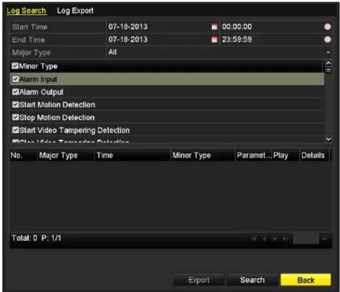
Figure 6.18 System Log Search Interface
- Click Log Search tab to enter Playback by System Logs.
Set search time and type and click Search button.

Figure 6.19 Result of System Log Search
- Choose a log with record file and click 📋 button to enter Playback interface.

If there is no record file at the time point of the log, the message box "No result found" will pop up.
- Playback management.
The toolbar in the bottom part of Playback interface can be used to control playing process.
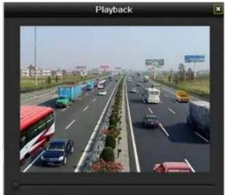
natural_image
Highway scene with multiple vehicles and a red double-decker bus, no visible text or symbolsFigure 6. 20 Interface: Playback by Log
6.1.7 Playing Back External Files
Purpose:
Perform the following steps to look up and play back files on external devices.
Steps:
- Enter Tag Search interface.
Menu>Playback
- Select the External File in the drop-down list on the top-left side.
The files are listed in the right-side list.
You can click the Refresh refresh the file list.
- Select and click the button to play back it.

Figure 6.21 Interface: External File Playback
6.2 Auxiliary Functions of Playback
6.2.1 Playing Back Frame by Frame
Purpose:
Play video files frame by frame, in order to check image details of the video when abnormal events happen.
Steps:
• Using a Mouse
Go to Playback interface and click button 🏠 and ▶ until the speed changes to Single frame. One click on the playback screen represents playback or adverse playback of one frame. It is also feasible to use button 🏠 in toolbar.
• Using the front panel
Press the ▼ button to set the speed to Single frame. One click on the playback screen or press ← button on the front panel represents playback or adverse playback of one frame.
6.2.2 Smart Search
Purpose:
In order to locate motion detection event easily and accurately in the playback progress bar, you are allowed to analyze a certain area (scene) dynamically, and to get all of the related motion detection events that occurred in this area.
Steps:
- Go to Playback interface and play the video.

Figure 6.22 Interface of Playback by Time
-
Click the button to go to analysis area selection interface.
-
Click and drag the mouse to draw area(s). You can click button to set the full screen as target searching area. After drawing area(s), press button execute smart search in this area.

Multi-area and full-screen searching modes are supported.

natural_image
Highway traffic scene with multiple lanes, vehicles, and a red overlay fence (no visible text or symbols)Figure 6. 23 Draw Area of Smart Search
The results of smart search will be marked as ■ the progress bar.

Figure 6. 24 Smart Search Result with Video List

Figure 6.25 Toolbar of Smart Search Playback

- represents normal recording (manual or schedule); ■ represents event recording (motion, alarm, motion | alarm, motion & alarm).
● Playback progress bar: use the mouse to click any point of the progress bar to locate special frames.
6.2.3 Digital Zoom
Steps:
- Click the button on the playback control bar to enter Digital Zoom interface.
- Use the mouse to draw a red rectangle and the image within it will be enlarged up to 16 times.

natural_image
Highway scene with vehicles and shipping containers, residential buildings in background (no visible text or symbols)Figure 6.26 Draw Area for Digital Zoom
- Right-click the image to exit the digital zoom interface.
6.2.4 Reverse Playback of Multi-channels
Purpose:
You can play back record files of multi-channel reversely. Up to 16-ch (with 1920*1080 resolution) simultaneous reverse playback is supported.
Steps:
- Enter Playback interface.
Menu>Playback - Check more than one checkboxes to select multiple channels and click to select a date on the calendar.

Figure 6. 27 4-ch Synchronous Playback Interface
- Click to play back the record files reversely.
Chapter 7 Backup
7.1 Backing up Record Files
Before you start:
Please insert the backup device(s) into the device.
7.1.1 Backing Up Using Normal Video Search
Purpose:
The record files can be backed up to various USB devices, such as USB flash drives, USB HDDs, and USB writer.
Backu Steps:
- E
Enter Export interface.
Menu>Export>Normal
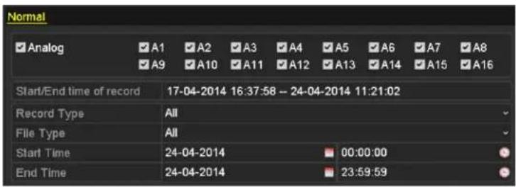
Figure 7.1 Normal Export Interface
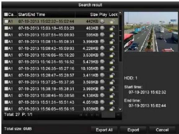
Figure 7.2 Result of Normal Video Search for Backup
- Set search condition and click Search button to enter the search result interface.
- Set search condition and click Search button to enter the search result interface.
Figure 7.2 Result of Normal Video Search for Backup
- Select record files you want to back up.
Click button to play the record file if you want to check it.
Check the checkbox before the record files you want to back up.

The size of the currently selected files is displayed in the lower-left corner of the window.
4. Export.
Click Export button and start backup.

If the inserted USB device is not recognized:
- Click the Refresh button.
- Reconnect device.
- Check for compatibility from vendor.
You can also format the USB device by clicking the Format button.
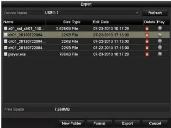
Figure 7.3 Export by Normal Video Search using USB Flash Drive

Figure 7.4 Export by Normal Video Search using USB Writer
Stay in the Exporting interface until all record files are exported with pop-up message box "Export finished".
5. Check backup result.
Choose the record file in Export interface and click button to check it.

The Player player.exe will be exported automatically during record file export.
Backup using eSATA HDDs

This function is only supported by the EZHD-TRF DVRs.
Steps:
- Enter Record>Advanced and set the usage of eSATA HDD at "Export".
Menu>Record>Advanced
Choose eSATA and set its usage at Export. Click Yes when pop-up message box "System will reboot automatically if the usage of eSATA is changed. Continue?"

The usages of eSATA HDD contain Record and Export. And changes in usage will take effective after rebooting the device.
- Enter Export interface.
Menu>Export>Normal
Set search condition and click Search button to enter the search result interface.
- Select record files you want to back up.
Click button play the record file if you want to check it.
Tick record files you want to back up.

The size of the currently selected files is displayed in the lower-left corner of the window.

Figure 7.5 Result of Normal Video Search for Backup
- Export.
Click Export button and start backup.

- Please format the eSATA first when using it for the first time.
- If the inserted eSATA HDD is not recognized:
- Click the Refresh button.
- Reconnect device.
- Check for compatibility from vendor.
You can also format eSATA HDD via the device.

Figure 7.6 Export by Normal Video Search Using eSATA HDD
Stay in the Exporting interface until all record files are exported with pop-up message "Export finished".
- Check backup result.
Choose the record file in Export interface and click button is check it.

The Player player.exe will be exported automatically during record file export.

Figure 7.7 Export Result Using eSATA HDD
7.1.2 Backing Up Using Event Search
Purpose:
Back up event-related recording files using USB devices, such as USB flash drives, USB HDDs, and USB writer.
Steps:
- Enter Export interface.
Menu>Export>Event
- Search for events.
1) Select the type of event from the dropdown list of Event Type; these are Alarm Input and Motion (selectable).

● Here we take the backup by motion detection as the example.
● Backup by alarm input is only supported by the EZHD-TRF DVRs.
2) Check the checkbox of cameras and set the search time.
3) Click Search button to enter the Search Result interface.

Figure 7.8 Event Search for Backup
- Select record files to export.
1) Select an alarm input in the list and click Quick Export button to enter Export interface.
2) Clicking Details button will take you to the interface with detailed information of all channels triggered by the event.
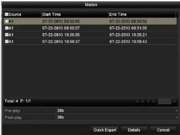
Figure 7.9 Result of Event Search
3) Click Details button to view detailed information of the record file, e.g. start time, end time, file size, etc.

The size of the currently selected files is displayed in the lower-right corner of the window.
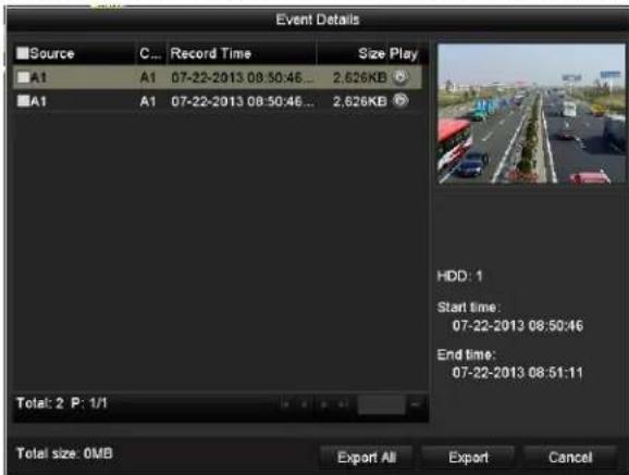
Figure 7. 10 Event Details Interface
4. Export.
Click the Export button and start backing up.

If the inserted USB device is not recognized:
- Click the Refresh button.
- Reconnect device.
- Check for compatibility from vendor.
You can also format USB flash drive or USB HDDs via the device.

Figure 7.11 Export by Event Using USB Flash Drive
Stay in the Exporting interface until all record files are exported with pop-up message "Export finished".
5. Check backup result.

The Player player.exe will be exported automatically during record file export.
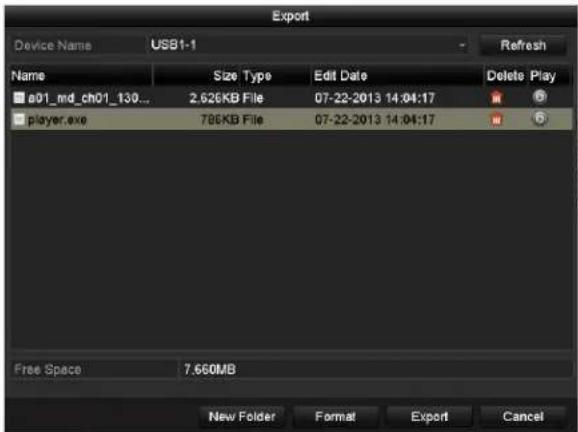
Figure 7.12 Checkup of Event Export Result Using USB Flash Drive
7.1.3 Backing up Video Clips
Purpose:
You may also select video clips to export directly during Playback, using USB devices, such as USB flash drives, USB HDDs, and USB writers.
Steps:
- Enter Playback interface.
Please refer to Chapter 6 Playback.

Figure 7.13 Interface of Playback by Time
-
During playback, use buttons 📁 and 📁 in the playback toolbar to start and stop clipping record file(s).
-
Click the icon ☐ to enter the Clips Export interface.

Figure 7.14 Clips Export

Up to 30 items of video clips can be selected for backup at one time.
- Click the button Export to export the selected video clips to the backup device.

If the inserted USB device is not recognized:
- Click the Refresh button.
- Reconnect device.
- Check for compatibility from vendor.
You can also format USB devices by clicking the Format button.

Figure 7. 15 Export Video Clips Using USB Flash Drive
Stay in the Exporting interface until all record files are exported with pop-up message "Export finished".
- Or a prompt will pop up when you quit the Playback interface if there are clips not saved.

Figure 7.16 Attention to Video Clip Saving
-
Click Yes to save video clips and enter Export interface, or click No to quit without saving video clips.
-
Check backup result.

The Player player.exe will be exported automatically during record file export.
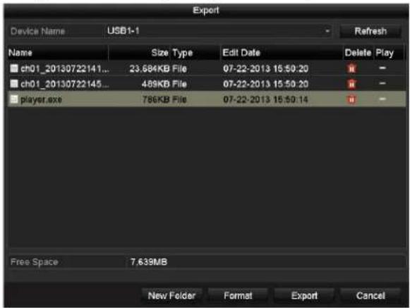
Figure 7.17 Checkup of Video Clips Export Result Using USB Flash Drive
7.2 Managing Backup Devices
Steps:
- Enter Search Result interface of record files.
Menu>Export>Normal
Set search condition and click Search button to enter Search Result interface.

At least one channel shall be selected.

Figure 7. 18 Normal Video Search for Backup
- Select record files you want to back up.
Click Export button to enter Export interface.

At least one recording file shall be selected.

Figure 7.19 Result of Normal Video Search for Backup
- Backup device management.
Management of USB flash drives, USB HDDs and eSATA HDDs

Figure 7.20 USB Flash Drive Management
Click New Folder button if you want to create a new folder in the backup device.
Select a record file or folder in the backup device and press button 📄 if you want to delete it.
Select a record file in the backup device and press button 📄 play it.
Click Format button to format the backup device.

If the inserted USB device is not recognized:
- Click the Refresh button.
- Reconnect device.
- Check for compatibility from vendor.
➢ Management of USB CD/DVD writers
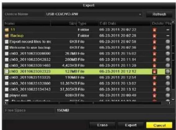
Figure 7.21 USB Writer Management
Click Erase button if you want to erase the files from a re-writable CD/DVD.

● There must be a re-writable CD/DVD when you attempt this operation.
- If the inserted USB writer is not recognized:
- Click the Refresh button.
- Reconnect device.
- Check for compatibility from vendor.
Chapter 8 Alarm Settings
8.1 Setting Motion Detection
Steps:
- Enter Motion Detection interface of Camera Management and choose a camera you want to set up motion detection. Menu> Camera> Motion
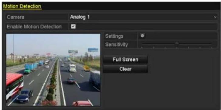
Figure 8.1 Motion Detection Setup Interface
- Set detection area and sensitivity.
Check ☑ checkbox to enable motion detection, use the mouse to draw detection area(s) and drag the sensitivity bar to set sensitivity.
Click set alarm response actions.

Figure 8.2 Set Detection Area and Sensitivity
- Click Trigger Channel tab and select one or more channels which will start to record or become full-screen monitoring when motion alarm is triggered.

Figure 8.3 Set Trigger Camera of Motion Detection
- Set arming schedule of the channel.
Select Arming Schedule tab to set the channel's arming schedule.
Choose one day of a week and up to eight time periods can be set within each day. Or you can click the Copy button to copy the time period settings to other day(s).

Time periods shall not be repeated or overlapped.

Figure 8.4 Set Arming Schedule of Motion Detection
- Click Linkage Action tab to set up alarm response actions of motion alarm (please refer to Chapter 8.7 Setting Alarm Response Actions).
Repeat the above steps to set up arming schedule of other days of a week.
Click the OK button to complete the motion detection settings of the channel.
- If you want to set motion detection for another channel, repeat the above steps or just copy the above settings to it.

You are not allowed to copy the "Trigger Channel" action.
8.2 Setting Sensor Alarms

This function is only supported by the EZHD-TRF DVRs.
Purpose:
Set up handling method of an external sensor alarm.
Steps:
- Enter Alarm Settings of System Configuration and select an alarm input.
Menu> Configuration> Alarm
Select Alarm Input tab to enter Alarm Input Settings interface.

Figure 8.5 Alarm Status Interface of System Configuration
- Set the handling method of the selected alarm input.
Check the Setting checkbox and click button to set its alarm response actions.

Figure 8.6 Alarm Input Settings Interface
- Select Trigger Channel tab and select one or more channels which will start to record or become full-screen monitoring when an external alarm input is triggered.
- Select Arming Schedule tab to set the channel's arming schedule.
Choose one day of a week and Max. eight time periods can be set within each day.

Time periods shall not be repeated or overlapped.

Figure 8.7 Set Arming Schedule of Alarm Input
- Select Linkage Action tab to set up alarm response actions of the alarm input (please refer to Chapter 8.7 Setting Alarm Response Actions).
Repeat the above steps to set up arming schedule of other days of a week. You can also use Copy button to copy an arming schedule to other days. - If necessary, select PTZ Linking tab and set PTZ linkage of the alarm input.
Set PTZ linking parameters and click the OK button to complete the settings of the alarm input.

Please check whether the PTZ or speed dome supports PTZ linkage.
One alarm input can trigger presets, patrol or pattern of more than one channel. But presets, patrols and patterns are exclusive.
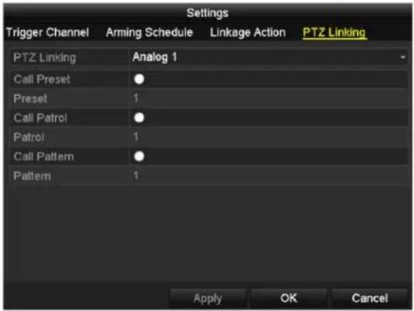
Figure 8.8 Set PTZ Linking of Alarm Input
- If you want to set handling action of another alarm input, repeat the above steps or just copy the above settings to it.

Figure 8.9 Copy Settings of Alarm Input
8.3 Detecting Video Loss
Purpose:
Detect video loss of a channel and take alarm response action(s).
Steps:
- Enter Video Loss interface of Camera Management and select a channel you want to detect.
Menu> Camera> Video Loss

Figure 8.10 Video Loss Setup Interface
- Set up handling method of video loss.
Check the checkbox of "Enable Video Loss Alarm".
Click button to set up handling method of video loss.
- Set arming schedule of the channel.
Select Arming Schedule tab to set the channel's arming schedule.
Choose one day of a week and up to eight time periods can be set within each day. Or you can click the Copy button to copy the time period settings to other day(s).

Time periods shall not be repeated or overlapped.

Figure 8.11 Set Arming Schedule of Video Loss
Repeat the above steps to set arming schedule of other days of a week. You can also use Copy button to copy an arming schedule to other days.
- Select Linkage Action tab to set up alarm response action of video loss (please refer to Chapter 8.7 Setting Alarm Response Actions).
- Click the OK button to complete the video loss settings of the channel.
Repeat the above steps to finish settings of other channels, or click the Copy button copy the above settings to them.
8.4 Detecting Video Tampering
Purpose:
Trigger alarm when the lens is covered and take alarm response action(s).
Steps:
- Enter Video Tampering interface of Camera Management and select a channel you want to detect video tampering. Menu> Camera> Video Tampering Detection
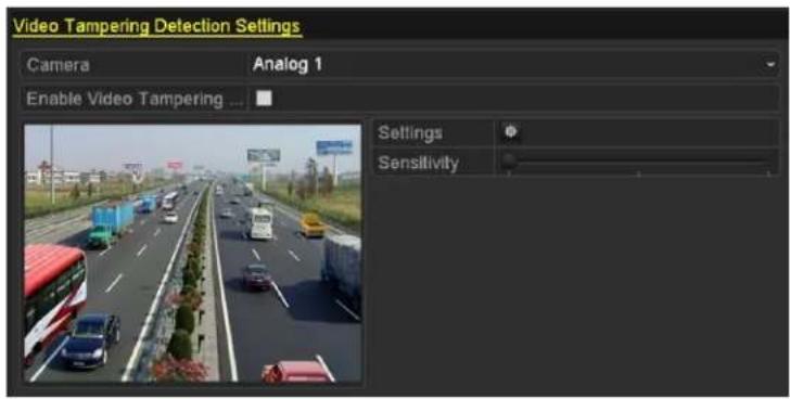
Figure 8. 12 Video Tempering Interface
- Check the checkbox of "Enable Video Tampering".
- Drag the sensitivity bar and choose a proper sensitivity level.
- Click 🙏 to set handling method of video tampering. Set arming schedule and alarm response actions of the channel.
1) Click Arming Schedule tab to set the arming schedule of response action.
2) Choose one day of a week and up to eight time periods can be set within each day.

Time periods shall not be repeated or overlapped.

Figure 8. 13 Set Arming Schedule of Video Tampering
3) Select Linkage Action tab to set alarm response actions of video tampering alarm (please refer to Chapter 8.7 Setting Alarm Response Actions).
Repeat the above steps to set arming schedule of other days of a week. You can also use Copy button to copy an arming schedule to other days.
4) Click the OK button to complete the video tampering settings of the channel.
Repeat the above steps to finish settings of other channels, or click the Copy button copy the above settings to them.
- Click the Apply button to save and activate the settings.
8.5 Setting All-day Video Quality Diagnostics
Purpose:
The device provides two ways to diagnose the video quality: manual and all-day. Perform the following steps to set the threshold of the diagnosing and the linkage actions.
Steps:
- Enter Video Quality Diagnostics settings interface of Camera Management and select a channel you want to detect video tampering. Menu> Camera> Video Quality Diagnostics
- Check the checkbox of Enable Video Quality Diagnostics.
- Enable and set the threshold of the diagnostic types, there are Blurred Image, Abnormal Brightness, and Color Cast. Check the corresponding checkbox of the diagnostic type, and adjust the threshold of it by clicking-and-dragging the bar.

The higher the threshold you set, the harder the exception will be detected.
- Click 🙏 to set handling method of video tampering. Set arming schedule and alarm response actions of the channel.
1) Click Arming Schedule tab to set the arming schedule of response action.
2) Choose one day of a week and up to eight time periods can be set within each day.

Time periods shall not be repeated or overlapped.

Figure 8.14 Set Arming Schedule of Video Quality Diagnostics
3) Select Linkage Action tab to set alarm response actions of video tampering alarm (please refer to Chapter 8.7 Setting Alarm Response Actions).
Repeat the above steps to set arming schedule of other days of a week. You can also use Copy button to copy an arming schedule to other days.
4) Click the OK button to complete the video tampering settings of the channel.
-
Click the Apply button to save and activate settings.
-
(Optional) you can copy the same settings to other cameras by clicking the Copy button.
8.6 Handling Exceptions
Purpose:
Exception settings refer to the handling method of various exceptions, e.g.
• HDD Full: The HDD is full.
• HDD Error: Writing HDD error, unformatted HDD, etc.
• Network Disconnected: Disconnected network cable.
• IP Conflicted: Duplicated IP address.
- Illegal Login: Incorrect user ID or password.
- Input/Recording Resolution Mismatch: The input resolution is smaller than the recording resolution.
• Record Exception: No space for saving recorded files.
Steps:
- Enter Exceptions interface and handle various exceptions.
Menu> Configuration> Exceptions

EZHD-TVL Models

EZHD-TRF Models
Figure 8. 15 Exception Settings Interface
- Check the checkbox of Enable Event Hint to display the 📄 (Event/Exception icon) when an exceptional event occurs. And click the icon ⚙ select the detailed event hint for display.

Click the icon 🙏 appears in the live view interface, and you can view the detailed information of the exceptional event. Click the button Set, and then you can select the detailed event hint for display.
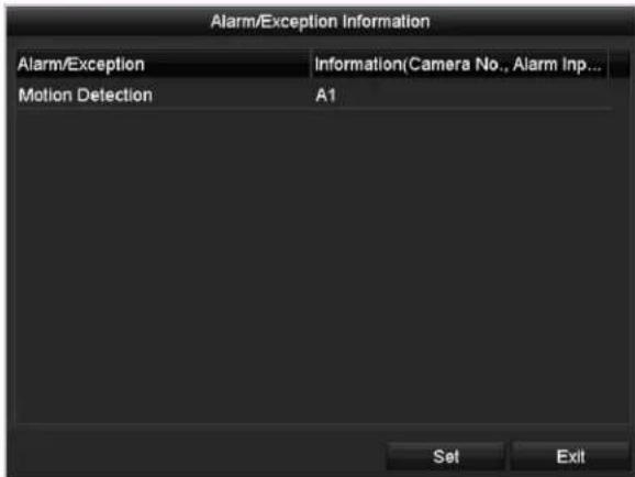
Figure 8.16 Detailed Event
- Set the alarm linkage actions. For details, see Chapter 8.7 Setting Alarm Response Actions.
- Click Apply to save the settings.
8.7 Setting Alarm Response Actions
Purpose:
Take alarm response actions will be activated when an alarm or exception occurs, including Full Screen Monitoring, Audible Warning (buzzer), Notify Surveillance Center, Send Email and Trigger Alarm Output.
Full Screen Monitoring
When an alarm is triggered, the local monitor (HDMI, VGA or CVBS monitor) display in full screen the video image from the alarming channel configured for full screen monitoring.
If alarms are triggered simultaneously in several channels, their full-screen images will be switched at an interval of 10 seconds (default dwell time). A different dwell time can be set by going to Menu > Configuration > Live View.
Auto-switch will terminate once the alarm stops and you will be taken back to the Live View interface.
Audible Warning
Trigger an audible beep when an alarm is detected.
Notify Surveillance Center
Sends an exception or alarm signal to remote alarm host when an event occurs. The alarm host refers to the PC installed with Remote Client.

The alarm signal will be transmitted automatically at detection mode when remote alarm host is configured. Please refer to Chapter 9.2.6 Configuring the Remote Alarm Host for details of alarm host configuration.
Send Email
Send an email with alarm information to a user or users when an alarm is detected.
Please refer to Chapter 9.2.11 Configuring Email for details of Email configuration.
Trigger Alarm Output
Trigger an alarm output when an alarm is triggered.

This function is only supported by the EZHD-TRF DVRs.
Steps:
- Enter Alarm Output interface.
Menu> Configuration> Alarm> Alarm Output
Select an alarm output and set alarm name and dwell time. Click 🙏 button to set the arming schedule of alarm output.

If "Manually Clear" is selected in the dropdown list of Dwell Time, you can clear it only by going to Menu> Manual> Alarm.
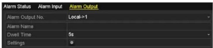
Figure 8.17 Alarm Output Settings Interface
- Set up arming schedule of the alarm output.
Choose one day of a week and up to 8 time periods can be set within each day.

Time periods shall not be repeated or overlapped.

Figure 8.18 Set Arming Schedule of Alarm Output
- Repeat the above steps to set arming schedule of other days of a week. You can also use Copy button to copy an arming schedule to other days.
Click the OK button to complete the arming schedule setting of alarm output.
- Click the Apply button to save the settings.
8.8 Triggering or Clearing Alarm Output Manually

This function is only supported by the EZHD-TRF DVRs.
Purpose:
Sensor alarm can be triggered or cleared manually. If “Manually Clear” is selected in the dropdown list of dwell time of an alarm output, the alarm can be cleared only by clicking Clear button in the following interface.
Steps:
Select the alarm output you want to trigger or clear and make related operations.
Menu> Manual> Alarm
Click Trigger/Clear button if you want to trigger or clear an alarm output.
Click Trigger All button if you want to trigger all alarm outputs.
Click Clear All button if you want to clear all alarm output.
| Alarm | ||
| Alarm Output No. | Alarm Name | Trigger |
| Local->1 | No | |
| Local->2 | No | |
| Local->3 | No | |
| Local->4 | No | |
Figure 8. 19 Clear or Trigger Alarm Output Manually
Chapter 9 Network Settings
9.1 Configuring General Settings
Purpose:
Network settings must be properly configured before you operate DVR over network.
Steps:
- Enter the Network Settings interface.
Menu > Configuration > Network
| NIC Type | 10M/100M/1000M Self-adaptive |
| Enable DHCP | |
| IPv4 Address | 172 .6 .23 .216 |
| IPv4 Subnet Mask | 255 .255 .255 .0 |
| IPv4 Default Gateway | 172 .6 .23 .1 |
| IPv6 Address 1 | fe80::8ee7:48ff:fe24:4214/64 |
| IPv6 Address 2 | |
| IPv6 Default Gateway | |
| MAC Address | 8c:e7:48:24:42:14 |
| MTU(Bytes) | 1500 |
| Preferred DNS Server | |
| Alternate DNS Server |
Figure 9.1 Network Settings Interface

- There is a self-adaptive 10M/100M network interface (EZHD-TVL4/8) and 10M/100M/100M on all other EZHD models. Select the General tab.
- In the General Settings interface, you can configure the following settings: IPv4 Address and subnet, IPv4 Gateway, MTU and DNS Server. Be sure to set the DNS server address if there will be any WAN connection for remote viewing.
If the DHCP server is available, you can check the checkbox for DHCP to automatically obtain an IP address and other network settings from that server.

The valid value of MTU is from 500 to 1500.
- After having configured the general settings, click the Apply button to save the settings.
9.2 Configuring Advanced Settings
9.2.1 Configuring PPPoE Settings
Purpose:
The DVR also allows access by Point-to-Point Protocol over Ethernet (PPPoE).
Steps:
- Enter the Network Settings interface.
Menu > Configuration > Network
- Select the PPPoE tab to enter the PPPoE Settings interface.
| Enable PPPOE | |
| User Name | |
| Password |
Figure 9.2 PPPoE Settings Interface
-
Check the PPPoE checkbox to enable this feature.
-
Enter User Name and Password for PPPoE access.

The User Name and Password should be assigned by your ISP.
-
Click the Apply button to save the settings.
-
After successful settings, the system asks you to reboot the device to enable the new settings, and the PPPoE dial-up is automatically connected after reboot.
You can go to Menu > Maintenance > System Info > Network interface to view the status of PPPoE connection.
9.2.2 Configuring DDNS
Purpose:
If your ISP connection is set to use DHCP as its default network connection, you should use Dynamic DNS (DDNS) to insure that you can reliably connect to your site. SIMPLEDDNS is highly recommended.
Prior registration with the DDNS service is often required before configuring the system to use DDNS.
Steps:
- Enter the Network Settings interface.
Menu >Configuration> Network
- Select the DDNS tab to enter the DDNS Settings interface, as shown in Figure 9.3.

Figure 9.3 DDNS Settings Interface
- Check the DDNS checkbox to enable this feature.
- Select DDNS Type. Five different DDNS types are selectable: IPServer, DynDNS, PeanutHull, NO-IP and SIMPLEDDNS.
- IPServer: Enter Server Address for IPServer.
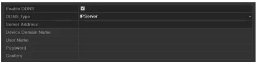
Figure 9.4 IPServer Settings Interface
- DynDNS:
1) Enter Server Address for DynDNS (i.e. members.dyndns.org).
2) In the NVR Domain Name text field, enter the domain obtained from the DynDNS website.
3) Enter the User Name and Password registered in the DynDNS website.

Figure 9.5 DynDNS Settings Interface
- PeanutHull: Enter the User Name and Password obtained from the PeanutHull website.

Figure 9.6 PeanutHull Settings Interface
- NO-IP:
Enter the account information in the corresponding fields. Refer to the DynDNS settings.
1) Enter Server Address for NO-IP.
2) In the NVR Domain Name text field, enter the domain obtained from the NO-IP website (www.no-ip.com).
3) Enter the User Name and Password registered in the NO-IP website.

Figure 9.7 NO-IP Settings Interface
- SIMPLEDDNS:
1) The Server Address of the SIMPLEDDNS server appears by default: www.simpleddns.com.
2) Enter the Device Domain Name. You can use the alias you registered in the SIMPLEDDNS server or define a new device domain name. If a new alias of the device domain name is defined in the NVR, it will replace the old one registered on the server. You can register the alias of the device domain name in the SIMPLEDDNS server first and then enter the alias to the Device Domain Name in the NVR; you can also enter the domain name directly on the NVR to create a new one.

Figure 9.8 SIMPLEDDNS Settings Interface
Register the device on the SIMPLEDDNS server.
1) Go to the SIMPLEDDNS website: www.simpleddns.com.
2) Click Register new user to register an account if you do not have one and use the account to log in.

Figure 9.9 Register an Account
3) In the Device Management interface, click Add to register the device.
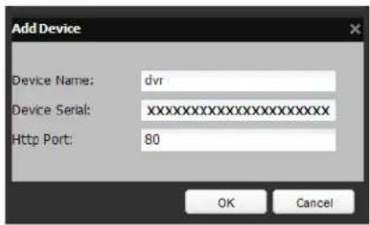
Figure 9.10 Register the Device
NOTE
Note: The device name can only contain the lower-case English letter, numeric and '-''; and it must start with the lower-case English letter and cannot end with '-''.
- IF THE WAN PORT USED FOR HTTP ACCESS IS OTHER THAN 80, IT IS ESSENTIAL THAT YOU ENTER THE ACTUAL WAN HTTP PORT INTO THE REGISTRATION DATA.
- Access the Device via Web Browser or Client Software
● After having successfully registered the device on the SIMPLEDDNS server, you can access your device via web browser or Client Software with the Device Domain Name (Device Name).
● Task 1: Access the Device via Web Browser
- Open a web browser, and enter http://www.simpleddns.com/alias in the address bar. Alias refers to the Device Domain Name on the device or the Device Name on the SIMPLEDDNS server.
Example: http://www.simpleddns.com/nvr
Note: If you mapped the HTTP port on your router and changed it to a port number other than 80, (Refer to Chapter 9.2.10 for the mapped HTTP port number) you must enter the mapped port info into the SIMPLEDDNS setup for the NVR so that port information is included when you are redirected from SIMPLEDDNS.COM/alias to your NVR.
- OPTION 2: Access the devices via CMS
For CMS, in the Add Device window, select and then edit the device information.
Nickname: Edit a name for the device as you want.
Server Address: www.simpleddns.com
Device Domain Name: It refers to the Device Domain Name on the device or the Device Name on the SIMPLEDDNS server you created.
User Name: Enter the user name of the device. By default it is admin.
Password: Enter the password of the device. By default it is 12345.
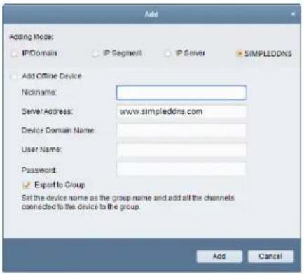
Figure 9.11 Access Device via CMS
- Click the Apply button to save and exit the interface.
9.2.3 Configuring NTP Server
Purpose:
A Network Time Protocol (NTP) Server can be configured on your DVR to ensure the accuracy of system date/time.
Steps:
- Enter the Network Settings interface.
Menu > Configuration > Network
- Select the NTP tab to enter the NTP Settings interface.

Figure 9.12 NTP Settings Interface
-
Check the Enable NTP checkbox to enable this feature.
-
Configure the following NTP settings:
-
Interval: Time interval between the two synchronizing actions with NTP server. The unit is minute.
• NTP Server: IP address of NTP server.
• NTP Port: Port of NTP server. -
Click the Apply button to save and exit the interface.

The time synchronization interval can be set from 1 to 10080 minutes, and the default value is 60 minutes. If the DVR is connected to a public network, you should use a NTP server that has a time synchronization function, such as the server at the National Time Center (IP Address: 210.72.145.44). If the DVR is set in a more customized network, NTP software can be used to establish a NTP server used for time synchronization.
9.2.4 Configuring SNMP
Purpose:
You can use SNMP protocol to get device status and parameters related information.
Steps:
- Enter the Network Settings interface.
Menu > Configuration > Network
- Select the SNMP tab to enter the SNMP Settings interface.
| Enable SNMP | |
| SNMP Version | V2 |
| SNMP Port | 161 |
| Read Community | public |
| Write Community | private |
| Trap Address | |
| Trap Port | 162 |
Figure 9.13 SNMP Settings Interface
- Check the Enable SNMP checkbox to enable this feature.
-
Configure the following SNMP settings:
-
Trap Address: IP Address of SNMP host.
- Trap Port: Port of SNMP host.
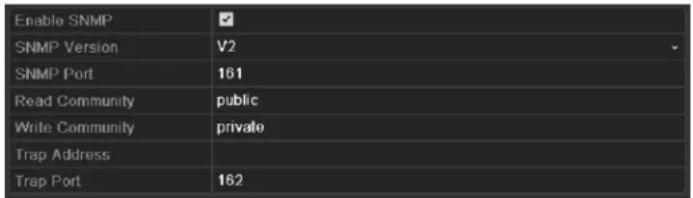
Figure 9. 14 Configure SNMP Settings
- Click the Apply button to save and exit the interface.

Before setting the SNMP, please download the SNMP software and manage to receive the device information via SNMP port. By setting the Trap Address, the DVR is allowed to send the alarm event and exception message to the surveillance center.
9.2.5 Configuring NAT
Purpose:
Universal Plug and Play (UPnP ^TM ) can permit the device seamlessly discover the presence of other network devices on the network and establish functional network services for data sharing, communications, etc. You can use the UPnP ^TM function to enable the fast connection of the device to the WAN via a router without port mapping.
Before you start:
If you want to enable the UPnP ^TM function of the device, you must enable the UPnP ^TM function of the router to which your device is
connected. When the network working mode of the device is set as multi-address, the Default Route of the device should be in the same network segment as that of the LAN IP address of the router.
Steps:
- Enter the Network Settings interface.
Menu > Configuration > Network
- Select the NAT tab to enter the UPnP ^TM settings interface.

Figure 9.15 UPnP™ Settings Interface
- Check ☑ checkbox to enable UPnP™.
- Select the Mapping Type as Manual or Auto in the drop-down list.
OPTION 1: Auto
If you select Auto, the Port Mapping items are read-only, and the external ports are set by the router automatically.
1) Click Apply button to save the settings.
2) You can click Refresh button to get the latest status of the port mapping.

Figure 9.16 UPnP™ Settings Finished-Auto
OPTION 2: Manual
If you select Manual as the mapping type, you can edit the external port on your demand by clicking ☐ to activate the External Port Settings dialog box.
Steps:
1) Click ☐ to activate the External Port Settings dialog box. Configure the external port No. for server port, http port and RTSP port respectively.

- You can use the default port No., or change it according to actual requirements.
● External Port indicates the port No. for port mapping in the router.
● The value of the RTSP port No. should be 554 or between 1024 and 65535, while the value of the other ports should be
between 1 and 65535 and the value must be different from each other. If multiple devices are configured for the UPnPTM settings under the same router, the value of the port No. for each device should be unique.
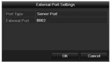
Figure 9.17 External Port Settings Dialog Box
2) Click Apply button to save the settings.
3) You can click Refresh button to get the latest status of the port mapping.
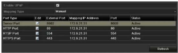
Figure 9. 18 UPnP™ Settings Finished-Manual
9.2.6 Configuring the Remote Alarm Host
Purpose:
With a remote alarm host configured, the DVR will send the alarm event or exception message to the host when an alarm is triggered. The remote alarm host must have the Network Video Surveillance software installed.
Steps:
-
Enter the Network Settings interface.
Menu > Configuration > Network -
Select the More Settings tab to enter the More Settings interface.
| Alarm Host IP | |
| Alarm Host Port | 0 |
| Server Port | 8000 |
| HTTP Port | 80 |
| Multicast IP | |
| RTSP Port | 554 |
Figure 9.19 More Settings Interface
- Enter Alarm Host IP and Alarm Host Port in the text fields.
The Alarm Host IP refers to the IP address of the remote PC on which the CMS (Client Management System) software (e.g., iVMS-4200) is installed, and the Alarm Host Port must be the same as the alarm monitoring port configured in the software (default
port is 7200).
| Alarm Host IP | 172.5 8.111 |
| Alarm Host Port | 7200 |
Figure 9.20 Configure Alarm Host
- Click the Apply button to save and exit the interface.
9.2.7 Configuring Multicast
Purpose:
The multicast can be configured to realize live view for more than 128 cameras through network.
A multicast address spans the Class-D IP range of 224.0.0.0 to 239.255.255.255. It is recommended to use the IP address ranging from 239.252.0.0 to 239.255.255.255.
Steps:
- Enter the Network Settings interface.
Menu > Configuration > Network
- Select the More Settings tab to enter the More Settings interface.
- Set Multicast IP. When adding a device to the CMS (Client Management System) software, the multicast address must be the same as the DVR's multicast IP.
| Server Port | 8000 |
| HTTP Port | 80 |
| Mulicast IP | 239.252.2.50 |
Figure 9.21 Configure Multicast
- Click the Apply button to save and exit the interface.
9.2.8 Configuring RTSP
Purpose:
The RTSP (Real Time Streaming Protocol) is a network control protocol designed for using in entertainment and communications systems to control streaming media servers.
Steps:
- Enter the Network Settings menu:
Menu > Configuration > Network
- Select the More Settings tab to enter the More Settings menu.

Figure 9.22 RTSP Settings Interface
-
Enter the RTSP port in the text field of RTSP Service Port. The default RTSP port is 554, and you can change it according to different requirements.
-
Click the Apply button to save and exit the menu.
9.2.9 Configuring Server and HTTP Ports
Purpose:
You can change the server and HTTP ports in the Network Settings menu. The default server port is 8000 and the default HTTP port is 80.
Steps:
- Enter the Network Settings interface.
Menu > Configuration > Network
- Select the More Settings tab to enter the More Settings interface, as shown in Figure 9. 23.
- Enter new Server Port and HTTP Port.
| Server Port | 8000 |
| HTTP Port | 80 |
| Multicast IP |
Figure 9. 23 Host/Others Settings Menu
- Enter the Server Port and HTTP Port in the text fields. The default Server Port is 8000 and the HTTP Port is 80, and you can change them according to different requirements.
- Click the Apply button to save and exit the interface.

The Server Port should be set to the range of 2000-65535 and it is used for remote client software access. The HTTP port is used for remote web browser access.
9.2.10 Configuring HTTPS Port
Purpose:
HTTPS provides authentication of the web site and associated web server that one is communicating with, which protects against Man-in-the-middle attacks. Perform the following steps to set the port number of https.
Example:
If you set the port number as 443 and the IP address is 192.0.0.64, you may access the device by inputting https://192.0.0.64:443 via the web browser.

The HTTPS port can be only configured through the web browser.
Steps:
- Open web browser, input the IP address of device, and the web server will select the language automatically according to the system language and maximize the web browser.
- Input the correct user name and password, and click Login button to log in the device.
- Enter the HTTPS settings interface.
Configuration > Remote Configuration > Network Settings > HTTPS
- Create the self-signed certificate or authorized certificate.

Figure 9.24 HTTPS Settings
OPTION 1: Create the self-signed certificate
1) Click the Create button to create the following dialog box.
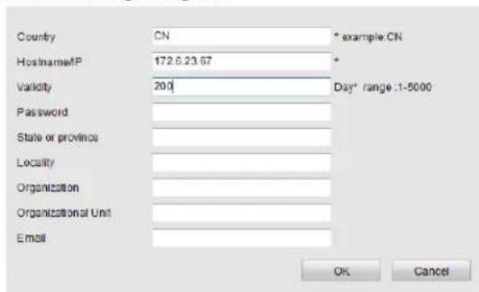
Figure 9. 25 Create Self-signed Certificate
2) Enter the country, host name/IP, validity and other information.
3) Click OK to save the settings.
1) Click the Create button to create the certificate request.
2) Download the certificate request and submit it to the trusted certificate authority for signature.
3) After receiving the signed valid certificate, import the certificate to the device.
OPTION 2: Create the authorized certificate
- There will be the certificate information after you successfully create and install the certificate.

Figure 9.26 Installed Certificate Property
-
Check the checkbox to enable the HTTPS function.
-
Click the Save button to save the settings.
9.2.11 Configuring Email
Purpose:
The system can be configured to send an Email notification to all designated users if an event is detected, e.g. an alarm or motion event is detected, etc.
Before configuring the Email settings, the DVR must be connected to a local area network (LAN) that maintains an SMTP mail server. The network must also be connected to either an intranet or the Internet depending on the location of the e-mail accounts to which you want to send notification. Additional, the Preferred DNS server must be configured.
Before you start:
Make sure you have configured the IPv4 Address, IPv4 Subnet Mask, IPv4 Gateway and the Preferred DNS Server in the Network Settings menu. Please refer to Chapter 9.1 Configuring General Settings for detailed information.
Steps:
- Enter the Network Settings interface.
Menu > Configuration > Network
- Select the Email tab to enter the Email Settings interface.

Figure 9.27 Email Settings Interface
- Configure the following Email settings:
Enable Server Authentication (optional): Check the checkbox to enable the server authentication feature.
User Name: The user account of sender's Email for SMTP server authentication.
Password: The password of sender's Email for SMTP server authentication.
SMTP Server: The SMTP Server IP address or host name (e.g., smtp.263xmail.com).
SMTP Port No.: The SMTP port. The default TCP/IP port used for SMTP is 25.
Enable SSL (optional): Click the checkbox to enable SSL if required by the SMTP server.
Sender: The name of sender.
Sender's Address: The Email address of sender.
Select Receivers: Select the receiver. Up to 3 receivers can be configured.
Receiver: The name of the receiver of the Email.
Receiver's Address: The Email address of the receiver.
Enable Attached Pictures: Check the checkbox of Enable Attached Picture if you want to send email with attached alarm images.
The interval is the time between two captures of the alarm images.
Interval: The interval refers to the time between two actions of sending attached pictures.
E-mail Test: Sends a test message to verify that the SMTP server can be reached.
- Click the Apply button to save the Email settings.
- You can click the Test button to test whether your Email settings work. The corresponding Attention message box pops up.

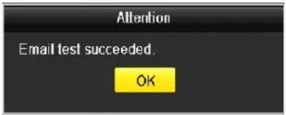
Figure 9.28 Email Testing Attention
9.2.12 Telnet Settings
Purpose:
Telnet function provides an easy way to get access to the DVR. You can see the advanced information about the device by inputting command; as well the configuration can also be realized through telnet connection.
Steps:
- Enter the Advanced settings interface, as shown in the Figure 9.29.
Configuration > Remote Configuration > Network Settings > Advanced

Figure 9.29 Telnet Settings Interface
- Check the checkbox of the Enable Telnet.
- Click the Save button to save the setting.
- You can open the Command Prompt window in your PC, and input "telnet IP Address" to connect with the DVR, as shown in the figure below.
Example:
If the IP address of the DVR is 192.0.0.64, you can input "telnet 192.0.0.64" and then press Enter to connect to the DVR.
![Microsoft Windows [Version 6.1.7%81] Copyright (c) 2009 Microsoft Corporation. All rights reserved. C:\Users\...\telnet 192.0.0.64_](/content/2026/05/995333/images/401084ed2e670a14ee3305fb7c420affb019f3e0150d9b9475ef92cea67b7215.jpg)
Figure 9.30 Connect to DVR

The telnet function turns invalid after the device shutting down or rebooting, you have to enable it again if required.
9.3 Checking Network Traffic
Purpose:
You can check the network traffic to obtain real-time information of DVR such as linking status, MTU, sending/receiving rate, etc.
Steps:
- Enter the Network Traffic interface.
Menu > Maintenance > Net Detect

line
| Time (Kbps) | Value | |-------------|-------| | 0 | 0 | | 1.5 | 465 | | 3.0 | 0 | | 4.5 | 0 | | 6.0 | 0 | | 7.5 | 0 | | 9.0 | 0 | | 10.5 | 0 | | 12.0 | 0 | | 13.5 | 0 | | 15.0 | 0 | | 16.5 | 0 | | 18.0 | 0 | | 19.5 | 0 | | 21.0 | 0 | | 22.5 | 0 | | 24.0 | 0 | | 25.5 | 0 | | 27.0 | 0 | | 28.5 | 0 |Figure 9.31 Network Traffic Interface
- You can view the sending rate and receiving rate information on the interface. The traffic data is refreshed every 1 second.
9.4 Configuring Network Detection
Purpose:
You can obtain network connecting status of DVR through the network detection function, including network delay, packet loss, etc.
9.4.1 Testing Network Delay and Packet Loss
Steps:
-
Enter the Network Traffic interface. Menu > Maintenance > Net Detect
-
Click the Network Detection tab to enter the Network Detection menu.
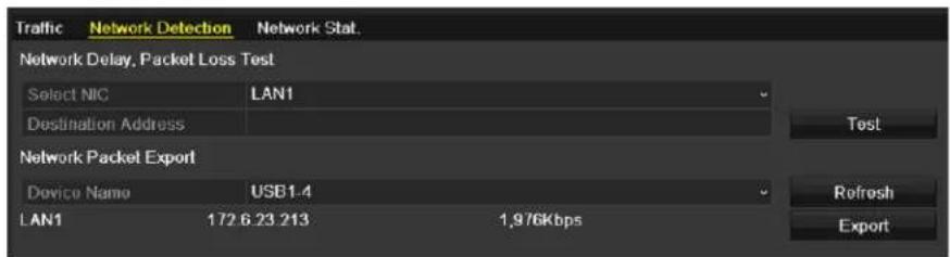
Figure 9.32 Network Detection Interface
-
Select a NIC to test network delay and packet loss.
-
Enter the destination address in the text field of Destination Address.
-
Click the Test button to start testing network delay and packet loss. The testing result pops up on the window. If the testing is failed, the error message box will pop up as well.


Figure 9.33 Testing Result of Network Delay and Packet Loss
9.4.2 Exporting Network Packet
Purpose:
By connecting the DVR to network, the captured network data packet can be exported to USB-flash disk, SATA and other local backup devices.
Steps:
- Enter the Network Traffic interface.
Menu > Maintenance > Net Detect
-
Click the Network Detection tab to enter the Network Detection interface.
-
Select the backup device from the dropdown list of Device Name.

Click the Refresh button if the connected local backup device cannot be displayed. When it fails to detect the backup device, please check whether it is compatible with the DVR. You can format the backup device if the format is incorrect.

Figure 9.34 Export Network Packet
-
Click the Export button to start exporting.
-
After the exporting is complete, click OK to finish the packet export.

Up to 1M data can be exported each time.
9.4.3 Checking Network Status
Purpose:
You can also check the network status and quick set the network parameters in this interface.
Steps:
Click Status on the right bottom of the page.
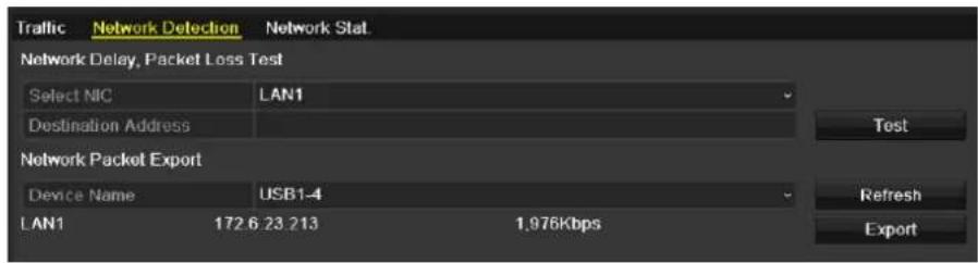
Figure 9.35 Checking Network Status
If the network is normal the following message box pops out.

Figure 9. 36 Network Status Checking Result
If the message box pops out with other information instead of this one, you can click Network button to show the quick setting interface of the network parameters.

Figure 9.37 Network Parameters Configuration
9.4.4 Checking Network Statistics
Purpose:
You can check the network statistics to obtain the real-time information of the device.
Steps:
- Enter the Network Statistics interface.
Menu > Maintenance> Net Detect
- Click the Network Stat. tab to enter the Network Statistics menu.

Figure 9.38 Network Stat. Interface
-
View the bandwidth of Remote Live View, bandwidth of Remote Playback, and bandwidth of Net Total Idle.
-
Click Refresh button to get the latest bandwidth statistics.
Chapter 10 HDD Management
10.1 Initializing HDDs
Purpose:
A newly installed hard disk drive (HDD) must be initialized before it can be used with your DVR.
Steps:
- Enter the HDD Information interface.
Menu > HDD>General.

Figure 10.1 HDD Information Interface
- Select HDD to be initialized.
- Click the Init button.
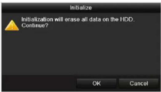
Figure 10.2 Confirm Initialization
- Select the OK button to start initialization.

Figure 10.3 Start Initialization
- After the HDD has been initialized, the status of the HDD will change from Uninitialized to Normal.

Figure 10.4 HDD Status Changes to Normal

Initializing the HDD will erase all data on it.
The HDDs which are free of working for a long time can be enabled to sleep, thus to decrease the power
consumption of the device and extend the life of the HDDs.
Click Menu > HDD > Advanced.

Figure 10.5 Enable HDD Sleeping
Check the checkbox of Enable HDD Sleeping (by default), and the HDDs which are free of working for a long time will be set to sleep.
Uncheck the checkbox of Enable HDD Sleeping, and the HDDs will be set to work for all time.
10.2 Managing Network HDD
Purpose:
You can add the allocated NAS or disk of IP SAN to DVR, and use it as network HDD.
Steps:
- Enter the HDD Information interface.
Menu > HDD>General

Figure 10.6 HDD Information Interface
- Click the Add button to enter the Add NetHDD interface, as shown in Figure 10.7.

Figure 10.7 HDD Information Interface
- Add the allocated NetHDD.
- Select the type to NAS or IP SAN.
- Configure the NAS or IP SAN settings.
- Add NAS disk:
1) Enter the NetHDD IP address in the text field.
2) Click Search to search the available NAS disks.
3) Select the NAS disk from the list shown below.
Or you can just manually enter the directory in the text field of NetHDD Directory.
4) Click OK to add the configured NAS disk.

Up to 8 NAS disks can be added.
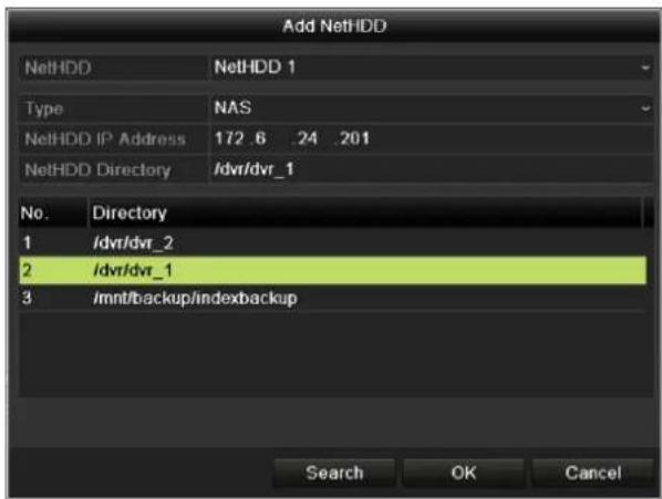
Figure 10.8 Add NAS Disk
- Add IP SAN:
1) Enter the NetHDD IP address in the text field.
2) Click the Search button to the available IP SAN disks.
3) Select the IP SAN disk from the list shown below.
4) Click the OK button to add the selected IP SAN disk.

Up to 1 IP SAN disk can be added.

Figure 10.9 Add IP SAN Disk
5) After having successfully added the NAS or IP SAN disk, return to the HDD Information menu. The added NetHDD will be displayed in the list.

If the added NetHDD is uninitialized, please select it and click the Init button for initialization.

Figure 10.10 Initialize Added NetHDD
10.3 Managing eSATA
Purpose:
When there is an external eSATA device connected to DVR, you can configure eSATA for the use of Record or Export, and you can manage the eSATA in the DVR.
Steps:
- Enter the Advanced Record Settings interface.
Menu >Record>Advanced
- Select the eSATA type to Export or Record from the dropdown list of eSATA.
Export: use the eSATA for backup. Refer to Backup using eSATA HDDs in Chapter 7.1.1 Backing up by Normal Video Search for operating instructions.
Record: use the eSATA for record. Refer to the following steps for operating instructions.

Figure 10.11 Set eSATA Mode
3. When the eSATA type is selected to Record, enter the HDD Information interface.
Menu > HDD>General
4. Edit the property of the selected eSATA, or initialize it is required.

Two storage modes can be configured for the eSATA when it is used for Record. Please refer to Chapter 10.4 Managing HDD Group and Chapter 10.5 Configuring Quota Mode for details.
| Label | Capacity | Status | Property | Type | Free Space | Gro... | Edit | Del... |
| 4 | 931.51GB | Normal | R/W | Local | 921GB | 1 | - | |
| 18 | 10,048MB | Uninitialized | R/W | NAS | 0MB | 1 | ||
| 25 | 931.51GB | Normal | R/W | eSATA | 894GB | 1 |
Figure 10.12 Initialize Added eSATA
10.4 Managing HDD Groups
10.4.1 Setting HDD Groups
Purpose:
Multiple HDDs can be managed in groups. Video from specified channels can be recorded onto a particular HDD group through HDD settings.
Steps:
- Enter the Storage Mode interface.
Menu > HDD > Advanced
- Set the Mode to Group, as shown in Figure 10. 13.
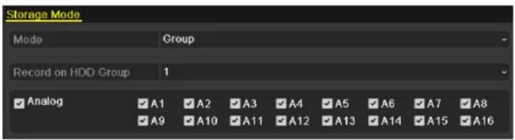
Figure 10.13 Storage Mode Interface
- Click the Apply button and the following Attention box will pop up.

Figure 10. 14 Attention for Reboot
- Click the Yes button to reboot the device to activate the changes.
- After reboot of device, enter the HDD Information interface.
Menu > HDD > General
- Select HDD from the list and click the icon to enter the Local HDD Settings interface, as shown in Figure 10.15.
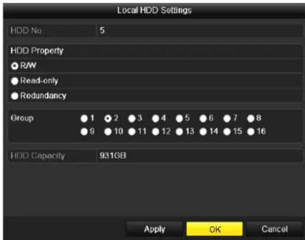
Figure 10.15 Local HDD Settings Interface
- Select the Group number for the current HDD.

The default group No. for each HDD is 1.
- Click the OK button to confirm the settings.

Figure 10. 16 Confirm HDD Group Settings
- In the pop-up Attention box, click the Yes button to finish the settings.
10.4.2 Setting HDD Properties
Purpose:
The HDD property can be set to redundancy, read-only or read/write (R/W). Before setting the HDD property, please set the storage mode to Group (refer to step1-4 of Chapter 10.4.1 Setting HDD Groups).
A HDD can be set to read-only to prevent important recorded files from being overwritten when the HDD becomes full in overwrite recording mode.
When the HDD property is set to redundancy, the video can be recorded both onto the redundancy HDD and the R/W HDD simultaneously so as to ensure high security and reliability of video data.
Steps:
- Enter the HDD Information interface.
Menu > HDD > General
- Select HDD from the list and click the icon to enter the Local HDD Settings interface, as shown in Figure 10.17.

Figure 10.17 Set HDD Property
- Set the HDD property to R/W, Read-only or Redundancy.
- Click the OK button to save the settings and exit the interface.
- In the HDD Information menu, the HDD property will be displayed in the list.

At least 2 hard disks must be added on your DVR when you want to set a HDD to Redundancy, and there is one HDD with R/W property.
10.5 Configuring Quota Mode
Purpose
Each camera can be configured with allocated quota for the storage of recorded files.
Steps
- Enter the Storage Mode interface.
Menu > HDD > Advanced
- Set the Mode to Quota, as shown in Figure 10. 18.

The DVR must be rebooted to enable the changes to take effect.
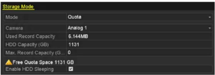
Figure 10. 18 Storage Mode Settings Interface
- Select a camera for which you want to configure quota.
- Enter the storage capacity in the text field of Max. Record Capacity (GB).
- You can copy the quota settings of the current camera to other cameras if required. Click the Copy button to enter the Copy Camera interface, as shown in Figure 10. 19.

Figure 10. 19 Copy Settings to Other Camera(s)
- Select the camera (s) to be configured with the same quota settings. You can also click the checkbox of Analog to select all cameras.
- Click the OK button to finish the Copy settings and back to the Storage Mode interface.
- Click the Apply button to apply the settings.

If the quota capacity is set to 0, then all cameras will use the total capacity of HDD for record.
10.6 Checking HDD Status
Purpose:
You may check the status of the installed HDDs on DVR so as to take immediate check and maintenance in case of HDD failure.
Checking HDD Status in HDD Information Interface
Steps:
- Enter the HDD Information interface.
Menu > HDD>General
- Check the status of each HDD which is displayed on the list, as shown in Figure 10. 20.

Figure 10.20 View HDD Status (1)

If the status of HDD is Normal or Sleeping, it works normally. If the status is Uninitialized or Abnormal, please initialize the HDD before use. And if the HDD initialization is failed, please replace it with a new one.
Checking HDD Status in System Information Interface
Steps:
- Enter the System Information interface.
Menu > Maintenance > System Info
- Click the HDD tab to view the status of each HDD displayed on the list, as shown in Figure 10. 21.
| Device Info | Camera | Record | Network | HDD | ||
| Label | Status | Capacity | Free Space | Property | Type | Group |
| 1 | Normal | 931.51GB | 900GB | R/W | Local | 1 |
| 17 | Normal | 199.97GB | 182GB | Redundancy | NAS | 1 |
Figure 10.21 View HDD Status (2)
10.7 Checking S.M.A.R.T Information
Purpose:
The S.M.A.R.T. (Self-Monitoring, Analysis and Reporting Technology) is a monitoring system for HDD to detect and report on various indicators of reliability in the hopes of anticipating failures.
Steps:
- Enter the HDD Detect interface.
Menu > HDD > HDD Detect
-
Click the S.M.A.R.T. Settings tab to enter the interface.
-
Select the HDD to view its S.M.A.R.T. information list, as shown in Figure 10. 22.

If you want to use the HDD even when the S.M.A.R.T. checking is failed, you can check the checkbox before the Continue to use this disk when self-evaluation is failed item.

Figure 10.22 S.M.A.R.T Settings Interface
10.8 Detecting Bad Sectors
Purpose:
You can detect the bad sector of the HDD to check the status of the HDD.
Steps:
- Enter the HDD Detect interface.
Menu>HDD>HDD Detect
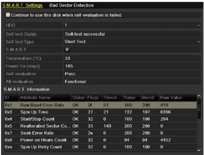
Figure 10.23 Bad Sector Detection
- Click the Bad Sector Detection tab to enter the interface.
- Select a HDD and click the Detect button to start detecting.
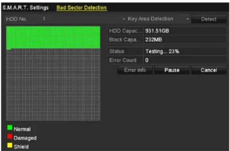
Figure 10. 24 Bad Sector Detecting
- You can click the Pause button to pause the detection and click the Resume button to resume the detection.
- If there is error information about the HDD, you can click the Error Info button to view the information.
10.9 Configuring HDD Error Alarms
Purpose:
You can configure the HDD error alarms when the HDD status is Uninitialized or Abnormal.
Steps:
- Enter the Exception interface.
Menu > Configuration > Exceptions - Select the Exception Type to HDD Error from the dropdown list.
- Check the checkbox(s) below to select the linkage action(s) for HDD error, as shown in Figure 10. 25. The linkage actions can be selected to: Audible Warning, Notify Surveillance Center, Send Email and Trigger Alarm Output.

Trigger alarm output is applicable to the EZHD-TRF models only.
Please refer to Chapter 8.7 Setting Alarm Response Actions.

Figure 10.25 Configure HDD Error Alarm
- When the Trigger Alarm Output is selected, you can also select the alarm output to be triggered from the list below.
- Click the Apply button to save the settings.
Chapter 11 Camera Settings
11.1 Configuring OSD Settings
Purpose:
You can configure the OSD (On-screen Display) settings for the camera, including date /time, camera name, etc.
Steps:
- Enter the OSD Configuration interface.
Menu > Camera > OSD - Select the camera to configure OSD settings.
- Edit the Camera Name in the text field.
- Configure the Display Name, Display Date and Display Week by checking the checkbox.
- Select the Date Format, Time Format, Display Mode and the OSD font.
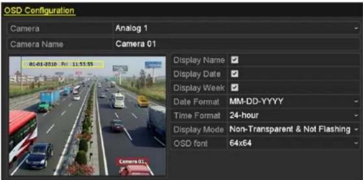
Figure 11.1 OSD Configuration Interface
- You can use the mouse to click and drag the text frame on the preview window to adjust the OSD position.
- Copy Camera Settings
1) If you want to copy the OSD settings of the current camera to other cameras, click the Copy button to enter the Copy Camera interface, as shown in Figure 11.2.

Figure 11.2 Copy Settings to Other Cameras
2) Select the camera (s) to be configured with the same OSD settings. You can also check the checkbox of Analog to select all cameras.
3) Click the OK button to finish the Copy settings and back to the OSD Configuration interface.
- Click the Apply button to apply the settings.
11.2 Configuring Privacy Mask
Purpose:
You are allowed to configure the four-sided privacy mask zones that cannot be viewed or recorded by the operator.
Steps:
- Enter the Privacy Mask Settings interface.
Menu > Camera > Privacy Mask
- Select the camera to set privacy mask.
- Check the checkbox of Enable Privacy Mask to enable this feature.
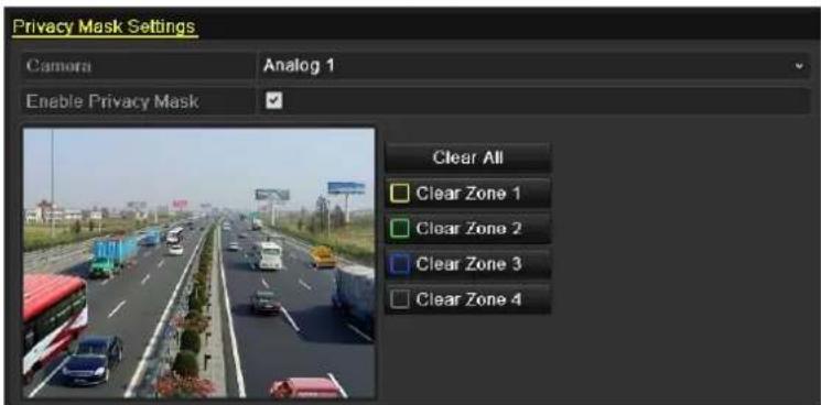
Figure 11.3 Privacy Mask Settings Interface
- Use the mouse to draw a zone on the window. The zones will be marked with different frame colors.

Up to 4 privacy mask zones can be configured, and the size of each area can be adjusted.
- The configured privacy mask zones on the window can be cleared by clicking the corresponding Clear Zone1-4 icons on the right side of the window, or click Clear All to clear all zones.

Figure 11.4 Set Privacy Mask Area
- You can click the Copy button to copy the privacy mask settings of the current camera to other cameras. Please refer to step 7 of Chapter 11.1 Configuring OSD Settings.
- Click the Apply button to save the settings.
11.3 Configuring Video Parameters
Steps:
- Enter the Image Settings interface.
Menu > Camera > Image
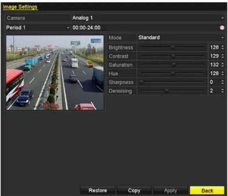
Figure 11.5 Image Settings Interface
-
Select the camera to set image parameters.
-
Two periods for different image settings are provided, select the period name in the dropdown list.
NOTE
The time periods cannot be overlapped with each other.
- Select the mode from the drop-down list of Mode, there are four modes selectable: Standard, Indoor, Dim Light and Outdoor.
- Adjust the image parameters according to actual needs. The parameters include Brightness, Contrast, Saturation, Hue, Sharpness and Denoising. You can also click Restore to set the parameters to the default settings.
- You can click Copy to copy the image settings of the current camera to other analog cameras.
- Click Apply to save the settings.
Chapter 12 DVR Management and Maintenance
12.1 Viewing System Information
Steps:
- Enter the System Information interface.
Menu > Maintenance > System Info
- You can click the Device Info, Camera, Record, Alarm, Network and HDD tabs to view the system information of the device.

Figure 12.1 System Information Interface

This alarm information is not available for the EZHD-TVL DVRs,
12.2 Searching and Exporting Log Files
Purpose:
The operation, alarm, exception and information of the DVR can be stored in log files, which can be viewed and exported at any time.
Steps:
- Enter the Log Search interface.
Menu > Maintenance > Log Search
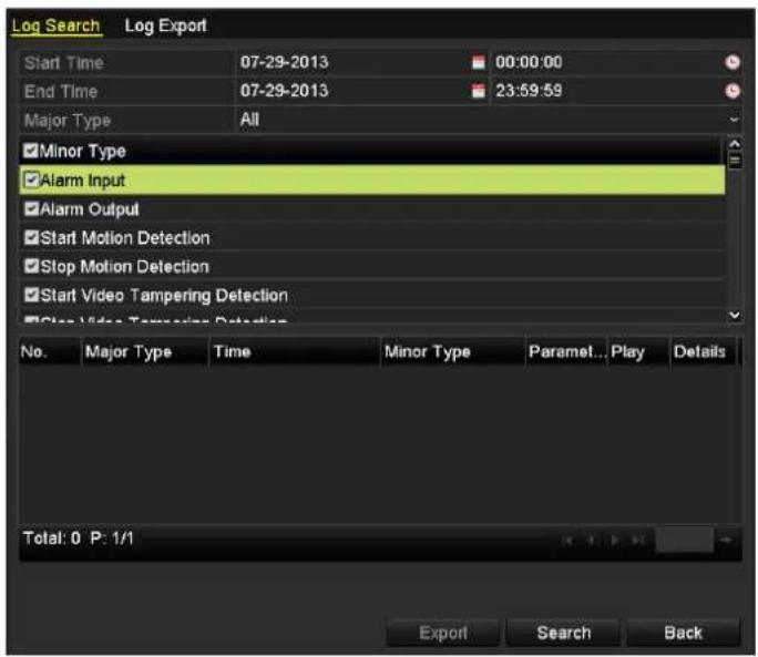
Figure 12.2 Log Search Interface
- Set the log search conditions to refine your search, including the Start Time, End Time, Major Type and Minor Type.
-
Click the Search button to start search log files.
-
The matched log files will be displayed on the list shown below.

Up to 2000 log files can be displayed each time.

Figure 12.3 Log Search Results
- You can click the √ button of each log or double-click it to view its detailed information, as shown in
Figure 12.4. And you can also click the button to view the related video files if available.

Figure 12.4 Log Details
- If you want to export the log files, click the Export button to enter the Export menu, as shown in Figure 12.
5.
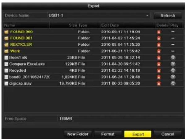
Figure 12.5 Export Log Files
- Select the backup device from the dropdown list of Device Name.
- Click the Export to export the log files to the selected backup device.
You can click the New Folder button to create new folder in the backup device, or click the Format button to format the backup device before log export.

- Please connect the backup device to DVR before operating log export.
- The log files exported to the backup device are named by exporting time, e.g., 20110514124841logBack.txt.
12.3 Importing/Exporting IP Camera Info
Purpose:
The information about added IP cameras can be formatted into an excel file and exported to a local device for backup, including the IP address, management port, password for admin, etc. And the exported file can be edited on a PC, to add or delete content, and copy the setting to other devices by importing the excel file to it.
Steps:
- Enter the camera management interface.
Menu > Camera > IP Camera Import/Export - Click the IP Camera Import/Export tab, the content of detected plugged external device appears.
- Click the Export button to export configuration files to the selected local backup device.
- To import a configuration file, select the file from the selected backup device and click the Import button.
After the importing process is completed, you must reboot the DVR.
12.4 Importing/Exporting Configuration Files
Purpose:
The configuration files of the DVR can be exported to local device for backup; and the configuration files of one DVR can be imported to multiple DVR devices if they are to be configured with the same parameters.
Steps:
- Enter the Import/Export Configuration File interface.
Menu > Maintenance > Import/Export
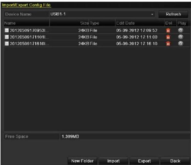
Figure 12.6 Import/Export Config File
-
Click the Export button to export configuration files to the selected local backup device.
-
To import a configuration file, select the file from the selected backup device and click the Import button. After the import process is completed, you must reboot the DVR.

After having finished the import of configuration files, the device will reboot automatically.
12.5 Upgrading System Firmware
Purpose:
The firmware on your DVR can be upgraded by local backup device or remote FTP server.
12.5.1 Upgrading by Local Backup Device
Steps:
- Connect your DVR with a local backup device where the update firmware file is located.
- Enter the Upgrade interface.
Menu > Maintenance > Upgrade
- Click the Local Upgrade tab to enter the local upgrade menu, as shown in Figure 12.7.

Figure 12.7 Local Upgrade Interface
- Select the update file from the backup device.
- Click the Upgrade button to start upgrading.
- After the upgrading is complete, reboot the DVR to activate the new firmware.
12.5.2 Upgrading by FTP
Before you start:
Configure PC (running FTP server) and DVR to the same Local Area Network. Run the 3^rd -party TFTP software on the PC and copy the firmware into the root directory of TFTP.
Steps:
- Enter the Upgrade interface.
Menu > Maintenance > Upgrade
- Click the FTP tab to enter the local upgrade interface, as shown in Figure 12.8.

Figure 12.8 FTP Upgrade Interface
- Enter the FTP Server Address in the text field.
- Click the Upgrade button to start upgrading.
- After the upgrading is complete, reboot the DVR to activate the new firmware.
12.6 Restoring Default Settings
Steps:
- Enter the Default interface.
Menu > Maintenance > Default

Figure 12.9 Restore Factory Default
- Click the OK button to restore the default settings.

Except the network parameters (including IP address, subnet mask, gateway, MTU, default route and server port), all other parameters of the device will be restored to factory default settings.
Chapter 13 Others
13.1 Configuring RS-232 Serial Port
Purpose:
The RS-232 port can be used in two ways:
Parameters Configuration: Connect a PC to the device through the PC serial port. Device parameters can be configured by using software such as HyperTerminal. The serial port parameters must be the same as the device's when connecting with the PC serial port.
Transparent Channel: Connect a serial device directly to the device. The serial device will be controlled remotely by the PC through the network.

RS-232 serial port is not used at this time.
Steps:
- Enter the RS-232 Settings interface.
Menu > Configuration > RS-232
| RS-232 Settings | ||
| Baud Rate | 115200 | ✓ |
| Data Bit | 8 | ✓ |
| Stop Bit | 1 | ✓ |
| Parity | None | ✓ |
| Flow Ctrl | None | ✓ |
| Usage | Console | ✓ |
Figure 1.1 RS-232 Settings Interface
- Configure RS-232 parameters, including baud rate, data bit, stop bit, parity, flow control and usage.
- Click Apply to save the settings.
13.2 Configuring General Settings
Purpose:
You can configure the output resolution, system time, mouse pointer speed, etc.
Steps:
- Enter the General Settings interface.
Menu > Configuration > General
- Select the General tab.
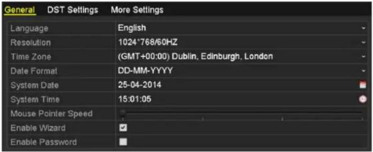
EZHD-TVL

EZHD-TRF
Figure 13.1 General Settings Interface
- Configure the following settings:
• Language: The default language used is English.
- CVBS Output Standard: Select the CVBS output standard to NTSC or PAL, which must be the same with the video input standard (for EZHD-TRF models only).
- Resolution: Select the output resolution, which must be the same with the resolution of the VGA/HDMI display.
• Time Zone: Select the time zone.
- Date Format: Select the date format.
• System Date: Select the system date.
• System Time: Select the system time.
- Mouse Pointer Speed: Set the speed of mouse pointer; 4 levels are configurable.
- Enable Wizard: Enable/disable the Wizard when the device starts up.
- Enable ID Authentication: Enable/disable the use of the login password.
- Click the Apply button to save the settings.
13.3 Configuring DST Settings
Steps:
-
Enter the General Settings interface. Menu >Configuration>General
-
Choose DST Settings tab.

Figure 13.2 DST Settings Interface
You can check the checkbox before the Auto DST Adjustment item.
Or you can manually check the Enable DST checkbox, and then you choose the date of the DST period.
13.4 Configuring More Settings
Steps:
- Enter the General Settings interface.
Menu > Configuration > General
- Click the More Settings tab to enter the More Settings interface, as shown in 0.

EZHD-TVL

EZHD-TRF
Figure 13. 3 More Settings Interface
- Configure the following settings:
• Device Name: Edit the name of DVR.
- Device No.: Edit the serial number of DVR. The Device No. can be set in the range of 1\~255, and the default No. is 255.
• CVBS Output Brightness: Adjust the video output brightness via the CVBS interface.
- Auto Logout: Set timeout time for menu inactivity. E.g., when the timeout time is set to 5 Minutes, then the system will exit from the current operation menu to live view screen after 5 minutes of menu inactivity.
- Menu Output Mode: You can choose the menu display on different video output. There are auto, HDMI/VGA and Main CVBS selectable.
- Click the Apply button to save the settings.
13.5 Managing User Accounts
Purpose:
There is a default account in the DVR: Administrator. The Administrator user name is admin and the password is 12345. The Administrator has the permission to add and delete user and configure user parameters.
13.5.1 Adding a User
Steps:
- Enter the User Management interface.
Menu > Configuration > User
| User Management | ||||||
| No. | User Name | Level | User's MAC Address | Pe... | Edit | Del... |
| 1 | admin | Admin | 00:00:00:00:00:00 | - | ||
| 2 | test | Guest | 00:00:00:00:00:00 | |||
Figure 13.4 User Management Interface
- Click the Add button to enter the Add User interface.

Figure 13.5 Add User Menu
- Enter the information for new user, including User Name, Password, Level and User's MAC Address.
Level: Set the user level to Operator or Guest. Different user levels have different operating permission.
- Operator: The Operator user level has permission of Local Log Search in Local Configuration, Remote Log Search and Two-way Audio in Remote Configuration and all operating permission in Camera Configuration.
- Guest: The Guest user has permission of Local Log Search in Local Configuration, Remote Log Search in Remote Configuration and only has the local/remote playback in the Camera Configuration.
User's MAC Address: The MAC address of the remote PC which logs onto the DVR. If it is configured and enabled, it only allows the remote user with this MAC address to access the DVR.
- Click the OK button to save the settings and go back to the User Management interface. The added new user will be displayed on the list, as shown in Figure 13.6.
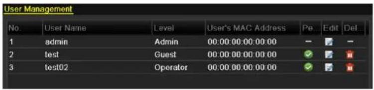
Figure 13.6 Added User Listed in User Management Interface
- Select the user from the list and then click the √ button to enter the Permission settings interface, as shown in Figure 13.7.

Figure 13.7 User Permission Settings Interface
- Set the operating permission of Local Configuration, Remote Configuration and Camera Configuration for the user.
Local Configuration
- Local Log Search: Searching and viewing logs and system information of DVR.
- Local Parameters Settings: Configuring parameters, restoring factory default parameters and importing/exporting configuration files.
- Local Advanced Operation: Operating HDD management (initializing HDD, setting HDD property), upgrading system firmware, clearing I/O alarm output.
- Local Shutdown Reboot: Shutting down or rebooting the DVR.
Remote Configuration
- Remote Log Search: Remotely viewing logs that are saved on the DVR.
- Remote Parameters Settings: Remotely configuring parameters, restoring factory default parameters and importing/exporting configuration files.
- Remote Serial Port Control: Configuring settings for RS-232 and RS-485 ports.
- Remote Video Output Control: Sending remote button control signal.
- Two-way Audio: Realizing two-way radio between the remote client and the DVR.
- Remote Alarm Control: Remotely arming (notify alarm and exception message to the remote client) and controlling the alarm output.
- Remote Advanced Operation: Remotely operating HDD management (initializing HDD, setting HDD property), upgrading system firmware, clearing I/O alarm output.
- Remote Shutdown/Reboot: Remotely shutting down or rebooting the DVR.
Camera Configuration
- Remote Live View: Remotely viewing live video of the selected camera(s).
- Local Manual Operation: Locally starting/stopping manual recording and alarm output of the selected camera(s).
- Remote Manual Operation: Remotely starting/stopping manual recording and alarm output of the selected camera(s).
- Local Playback: Locally playing back recorded files of the selected camera(s).
- Remote Playback: Remotely playing back recorded files of the selected camera(s).
- Local PTZ Control: Locally controlling PTZ movement of the selected camera(s).
- Remote PTZ Control: Remotely controlling PTZ movement of the selected camera(s).
-
Local Video Export: Locally exporting recorded files of the selected camera(s).
-
Click the OK button to save the settings and exit interface.

Only the admin user account has the permission of restoring factory default parameters.
13.5.2 Deleting a User
Steps:
- Enter the User Management interface.
Menu > Configuration > User
- Select the user to be deleted from the list, as shown in Figure 13.8.
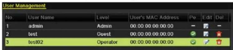
Figure 13.8 Delete a User
- Click the icon to delete the selected user.
13.5.3 Editing a User
Steps:
- Enter the User Management interface.
Menu > Configuration > User
- Select the user to be edited from the list, as shown in Figure 13.9.
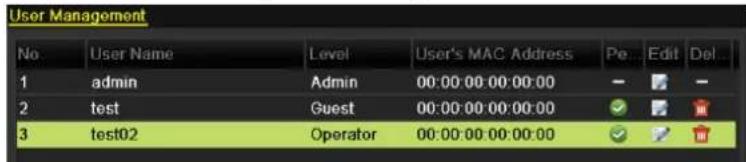
Figure 13.9 Edit a User
- Click the icon to enter the Edit User interface, as shown in Figure 13. 10 and Figure 13. 11.
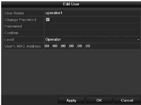
Figure 13.10 Edit User Interface-operator and guest
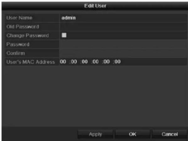
Figure 13.11 Edit User Interface-admin
- Edit the parameters.
- Operator and Guest
You can edit the user information, including user name, password, permission level and MAC address.
Check the checkbox of Change Password if you want to change the password, and input the new one in the text field of Password and Confirm.
- Admin
You are only allowed to edit password and MAC address. Check the checkbox of Change Password if you want to change the password, and the input the correct old password, and the new one in the text field of
Password and Confirm.
- Click the OK button to save the settings and exit the interface.
13.6 Logging out/Shutting down/Rebooting
Device
Steps:
- Enter the Shutdown interface.
Menu > Shutdown
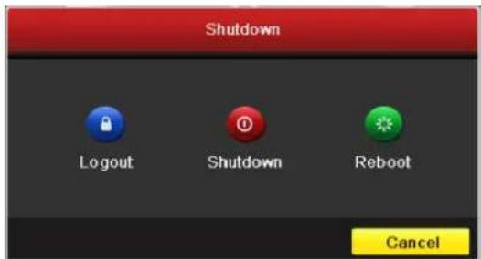
Figure 13.12 Shutdown Menu
- Click the Logout button to log out, or
Click the Shutdown button to shut down the device, or
Click the Reboot button to reboot the device.

After you have logged out the system, menu operation on the screen is invalid. It is required a user name and password to login the system.
Appendix
Glossary
- Dual Stream: Dual stream is a technology used to record high resolution video locally while transmitting a lower resolution stream over the network. The two streams are generated by the DVR, with the main stream having a maximum resolution of 1080P and the sub-stream having a maximum resolution of CIF.
- DVR: Acronym for Digital Video Recorder. A DVR is device that is able to accept video signals from analog cameras, compress the signal and store it on its hard drives.
- HDD: Acronym for Hard Disk Drive. A storage medium which stores digitally encoded data on platters with magnetic surfaces.
- DHCP: Dynamic Host Configuration Protocol (DHCP) is a network application protocol used by devices (DHCP clients) to obtain configuration information for operation in an Internet Protocol network.
- HTTP: Acronym for Hypertext Transfer Protocol. A protocol to transfer hypertext request and information between servers and browsers over a network
- PPPoE: PPPoE, Point-to-Point Protocol over Ethernet, is a network protocol for encapsulating Point-to-Point Protocol (PPP) frames inside Ethernet frames. It is used mainly with ADSL services where individual users connect to the ADSL transceiver (modem) over Ethernet and in plain Metro Ethernet networks.
- DDNS: Dynamic DNS is a method, protocol, or network service that provides the capability for a networked device, such as a router or computer system using the Internet Protocol Suite, to notify a domain name server to change, in real time (ad-hoc) the active DNS configuration of its configured hostnames, addresses or other information stored in DNS.
• Hybrid DVR: A hybrid DVR is a combination of a DVR and NVR. - NTP: Acronym for Network Time Protocol. A protocol designed to synchronize the clocks of computers over a network.
- NTSC: Acronym for National Television System Committee. NTSC is an analog television standard used in such countries as the United States and Japan. Each frame of an NTSC signal contains 525 scan lines at 60Hz.
- NVR: Acronym for Network Video Recorder. An NVR can be a PC-based or embedded system used for centralized management and storage for IP cameras, IP Domes and other DVRs.
- PAL: Acronym for Phase Alternating Line. PAL is also another video standard used in broadcast televisions systems in large parts of the world. PAL signal contains 625 scan lines at 50Hz.
- PTZ: Acronym for Pan, Tilt, Zoom. PTZ cameras are motor driven systems that allow the camera to pan left and right, tilt up and down and zoom in and out.
- USB: Acronym for Universal Serial Bus. USB is a plug-and-play serial bus standard to interface devices to a host computer.
Troubleshooting
- No image displayed on the monitor after the device is starting up normally.
Possible Reasons:
a) No VGA or HDMI connections.
b) Connection cable is damaged.
c) Input mode of the monitor is incorrect.
Steps:
- Verify the device is connected with the monitor via HDMI or VGA cable.
If not, please connect the device with the monitor and reboot. - Verify the connection cable is good.
If there is still no image display on the monitor after rebooting, please check if the connection cable is good, and change a cable to connect again. - Verify Input mode of the monitor is correct.
Please check the input mode of the monitor matches with the output mode of the device (e.g. if the output mode of DVR is HDMI output, then the input mode of monitor must be the HDMI input). And if not, please modify the input mode of monitor. - Check if the fault is solved by the step 1 to step 3.
If it is solved, finish the process.
If not, please contact the engineer from our company to do the further process.
• There is a beep sound after a new bought device starts up.
Possible Reasons:
a) No HDD is installed in the device.
b) The installed HDD has not been initialized.
c) The installed HDD is not compatible with the device or is broken-down.
Steps:
- Verify at least one HDD is installed in the device.
1) If not, please install the compatible HDD.

Please refer to the "Quick Operation Guide" for the HDD installation steps.
2) If you do not want to install a HDD, select "Menu>Configuration > Exceptions", and uncheck the Audible Warning checkbox of "HDD Error".
- Verify the HDD is initialized.
1) Select "Menu>HDD>General".
2) If the status of the HDD is "Uninitialized", please check the checkbox of corresponding HDD and click the "Init" button.
- Verify the HDD is detected or is in good condition.
1) Select "Menu>HDD>General".
2) If the HDD is not detected or the status is “Abnormal”, please replace the dedicated HDD according to the requirement.
- Check if the fault is solved by the step 1 to step 3.
1) If it is solved, finish the process.
2) If not, please contact the engineer from our company to do the further process.
• Live view stuck when video outputs locally.
Possible Reasons:
a) The frame rate has not reached the real-time frame rate.
Steps:
- Check the parameters of Main Stream (Normal) and Main Stream (Event).
Select "Menu > Record > Encoding > Record", and set the resolution of Main Stream (Event) the same as the one of Main Stream (Normal). - Verify the frame rate is real-time frame rate.
Select "Menu > Record > Parameters > Record", and set the Frame rate to Full Frame. - Check if the fault is solved by the above steps.
If it is solved, finish the process.
If not, please contact the engineer from our company to do the further process.
- When using the device to get the live view audio, there is no sound or there is too much noise, or the volume is too low.
Possible Reasons:
a) Cable between the pickup and camera is not connected well; impedance mismatches or incompatible.
b) The stream type is not set as "Video & Audio".
Steps:
- Verify the cable between the pickup and camera is connected well; impedance matches and compatible.
- Verify the setting parameters are correct.
Select "Menu > Record > Parameters > Record", and set the Stream Type as "Audio & Video". - Check if the fault is solved by the above steps.
If it is solved, finish the process.
If not, please contact the engineer from our company to do the further process.
- The image gets stuck when DVR is playing back by single or multi-channel cameras.
Possible Reasons:
a) The frame rate is not the real-time frame rate.
b) The DVR supports up to 16-channel synchronize playback at the resolution of 4CIF, if you want a 16-channel synchronize playback at the resolution of 720p, the frame extracting may occur, which leads to a slight stuck.
Steps:
- Verify the frame rate is real-time frame rate.
Select "Menu > Record > Parameters > Record", and set the Frame Rate to "Full Frame". -
Verify the hardware can afford the playback.
Reduce the channel number of playback.
Select "Menu > Record > Encoding > Record", and set the resolution and bitrate to a lower level. -
Reduce the number of local playback channel.
Select "Menu > Playback", and uncheck the checkbox of unnecessary channels. -
Check if the fault is solved by the above steps.
If it is solved, finish the process.
If not, please contact the engineer from our company to do the further process.
- No record file found in the device local HDD, and the prompt "No record file found" pops up when you search the record files.
Possible Reasons:
a) The time setting of system is incorrect.
b) The search condition is incorrect.
c) The HDD is error or not detected.
Steps:
- Verify the system time setting is correct.
Select "Menu > Configuration > General > General", and verify the "Device Time" is correct.
- Verify the search condition is correct.
Select "Playback", and verify the channel and time are correct.
- Verify the HDD status is normal.
Select "Menu > HDD > General" to view the HDD status, and verify the HDD is detected and can be read and written normally.
- Check if the fault is solved by the above steps.
If it is solved, finish the process.
If not, please contact the engineer from our company to do the further process.
List of Compatible IP Cameras
All KT&C OMNI-IP Plug-and-Play cameras are supported, as are any other models that operate in plug-and-play mode with KT&C OMNI-IP NVRs.
KT&C America, Inc.
www.ktncusa.com
New Jersey Office
40 Lane Road 1st Floor
Fairfield, NJ 07004
T: 973 276 0118
F:9732760116
New York Office
200 Pkwy Drive South Suite 200
Hauppauge, NY 11788
T:6318640118
F:6318640116
California Office
3240 Wilshire Blvd Suite 501
Los Angeles, CA 90010
T: 213 381 0061
F:213 381 0064



- Triple Technology Recorders
- 960H - EZHD - IP
- EZHD-TVL4/EZHD-TVL8/EZHD-TVL16
- Regulatory information FCC information
- FCC conditions
- EU Conformity Statement
- Preventive and Cautionary Tips
- Trademarks and Registered Trademarks
- Product Key Features
- General
- Local Monitoring
- HDD Management
- Recording and Playback
- Backup
- Alarm and Exception
- Other Local Functions
- Network Functions
- Table of Contents
- Chapter 1 Introduction....12
- Wiring of Alarm Outputs 22
- Chapter 2 Getting Started....25
- Chapter 3 Live View 37
- Chapter 4 PTZ Controls.... 48
- Chapter 5 Recording Settings .... 59
- Chapter 6 Playback .... 78
- Chapter 7 Backup....97
- Chapter 8 Alarm Settings....110
- Chapter 9 Network Settings....126
- Chapter 10 ......HDD Management 147
- Chapter 11 ......Camera Settings 161
- Chapter 12 DVR Management and Maintenance....165
- Chapter 13 Others....173
- Appendix 183
- Chapter 1 Introduction
- Front Panels
- IR Remote Control Operations
- Troubleshooting the Remote Control:
- Steps:
- USB Mouse Operation
- Input Method Description
- % ^ * + = \ | ~
- EZHD-TVL Rear Panels
- RS-485 Connection EZHD-TVL
- To connect PTZ to the DVR:
- EZHD-TRF Rear Panels
- EZHD-TRF Peripheral Connections
- Wiring of Alarm Inputs
- Wiring of Alarm Outputs
- Example:
- Alarm Connection
- RS-485 Connection
- Chapter 2 Getting Started
- Starting Up and Shutting Down the DVR
- Purpose:
- Before you start:
- Starting up the DVR
- Shutting down the DVR
- • OPTION 1: Standard shutdown
- - OPTION 2: By operating the front panel button (for EZHD-TRF series)
- Rebooting the DVR
- Using the Wizard for Basic Configuration
- Adding/Connecting OMNI IP Cameras
- Adding Online OMNI IP PnP Cameras
- • OPTION 1:
- • OPTION 2:
- Editing the Connected IP Cameras and Configuring Customized Protocols
- To edit advanced parameters:
- Chapter 3 Live View
- Introduction to Live View
- Live View Icons
- Operations in Live View Mode
- Front Panel Operation
- Using the Mouse in Live View
- Using an Auxiliary Monitor [EZHD-TRF models]
- Main/Aux Output Switching [EZHD-TRF models]
- Quick Setting Toolbar in Live View Mode
- Channel-zero Encoding
- Adjusting Live View Settings
- Manual Video Quality Diagnostics
- User Logout
- Chapter 4 PTZ Controls
- Configuring PTZ Settings
- Setting PTZ Presets, Patrols & Patterns
- Customizing Presets
- Calling Presets
- Customizing Patrols
- Calling Patrols
- Customizing Patterns
- Calling Patterns
- Customizing Linear Scan Limit
- Calling Linear Scan
- One-touch Park
- PTZ Control Panel
- OPTION 1:
- OPTION 2:
- Chapter 5 Recording Settings
- Configuring Encoding Parameters
- Figure 5.3 Record Encoding
- Set the encoding parameters for recording.
- Configuring Record Schedule
- Edit the schedule
- Configuring Motion Detection Record
- Configure the schedule.
- Configuring Alarm Triggered Record
- Manual Record
- Configuring Holiday Record
- Configuring Redundant Recording [EZHD-TRF]
- Configuring HDD Group for Recording
- File Protection
- Chapter 6 Playback
- Playing Back Record Files
- Playing Back by Channel
- - OPTION 1
- - OPTION 2
- Playback management.
- Playing Back by Time
- Playing Back by Event Search
- Playback management.
- Playing Back by Tag
- Before playing back by tag:
- Smart Playback
- Playing Back by System Logs
- Playing Back External Files
- Auxiliary Functions of Playback
- Playing Back Frame by Frame
- Smart Search
- Digital Zoom
- Reverse Playback of Multi-channels
- Chapter 7 Backup
- Backing up Record Files
- Backing Up Using Normal Video Search
- Export.
- Check backup result.
- Backup using eSATA HDDs
- Backing Up Using Event Search
- Backing up Video Clips
- Managing Backup Devices
- Chapter 8 Alarm Settings
- Setting Motion Detection
- Setting Sensor Alarms
- Detecting Video Loss
- Figure 8.11 Set Arming Schedule of Video Loss
- Detecting Video Tampering
- Setting All-day Video Quality Diagnostics
- Handling Exceptions
- Setting Alarm Response Actions
- Full Screen Monitoring
- Audible Warning
- Notify Surveillance Center
- Send Email
- Trigger Alarm Output
- Triggering or Clearing Alarm Output Manually
- Chapter 9 Network Settings
- Configuring General Settings
- Configuring Advanced Settings
- Configuring PPPoE Settings
- Configuring DDNS
- - NO-IP:
- - SIMPLEDDNS:
- Register the device on the SIMPLEDDNS server.
- NOTE
- Configuring NTP Server
- Configuring SNMP
- Configuring NAT
- OPTION 1: Auto
- OPTION 2: Manual
- Configuring the Remote Alarm Host
- Configuring Multicast
- Configuring RTSP
- Configuring Server and HTTP Ports
- Configuring HTTPS Port
- OPTION 1: Create the self-signed certificate
- OPTION 2: Create the authorized certificate
- Configuring Email
- Telnet Settings
- Checking Network Traffic
- Configuring Network Detection
- Testing Network Delay and Packet Loss
- Exporting Network Packet
- Checking Network Status
- Checking Network Statistics
- Chapter 10 HDD Management
- Initializing HDDs
- Managing Network HDD
- - Add IP SAN:
- Managing eSATA
- Managing HDD Groups
- Setting HDD Groups
- Setting HDD Properties
- Configuring Quota Mode
- Purpose
- Steps
- Checking HDD Status
- Checking S.M.A.R.T Information
- Detecting Bad Sectors
- Configuring HDD Error Alarms
- Chapter 11 Camera Settings
- Configuring OSD Settings
- Configuring Privacy Mask
- Configuring Video Parameters
- Chapter 12 DVR Management and Maintenance
- Viewing System Information
- Searching and Exporting Log Files
- Importing/Exporting IP Camera Info
- Importing/Exporting Configuration Files
- Upgrading System Firmware
- Upgrading by Local Backup Device
- Upgrading by FTP
- Restoring Default Settings
- Chapter 13 Others
- Configuring RS-232 Serial Port
- Configuring General Settings
- Configuring DST Settings
- Configuring More Settings
- Managing User Accounts
- Adding a User
- Local Configuration
- Remote Configuration
- Camera Configuration
- Deleting a User
- Editing a User
- Logging out/Shutting down/Rebooting
- Device
- Appendix
- Glossary
- Troubleshooting
- - No image displayed on the monitor after the device is starting up normally.
- Possible Reasons:
- • There is a beep sound after a new bought device starts up.
- List of Compatible IP Cameras
Brand : KT&C
Model : EZHD-TRF8
Category : Voice recorder