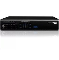
K9-s400 - Voice recorder KT&C - Free user manual and instructions
Find the device manual for free K9-s400 KT&C in PDF.


| Product Type | Digital Voice Recorder |
| Brand | KT&C |
| Model | K9-s400 |
| Dimensions | Approx. 10.2 x 3.0 x 1.5 cm |
| Weight | Approx. 50 g |
| Recording Format | MP3 / WAV |
| Storage Capacity | Built-in 8GB |
| Recording Time | Up to 72 hours (MP3 128kbps) |
| Battery Type | Rechargeable Lithium-ion |
| Battery Life | Up to 15 hours continuous recording |
| Power Input | USB 5V DC |
| Microphone | Built-in high-sensitivity stereo microphone |
| Speaker | Built-in speaker for playback |
| Connectivity | USB 2.0 for data transfer |
| Audio Jack | 3.5mm headphone/earphone jack |
| Controls | Play/Pause, Record, Stop, Volume, Menu |
| Display | LED indicator for recording status |
| Functions | Voice activation (VOX), A-B repeat, password protection |
| Special Features | Timestamp recording, variable speed playback |
| Storage Medium | Internal flash memory (non-removable) |
| Operating System | Plug-and-play, no driver needed for Windows/Mac |
| Software | None required; files appear as external drive |
| Maintenance | Clean with dry cloth; avoid moisture |
| Safety | Keep away from magnetic fields; do not disassemble |
| Spare Parts and Repairability | Not user-serviceable; contact support |
Frequently Asked Questions - K9-s400 KT&C
User questions about K9-s400 KT&C
0 question about this device. Answer the ones you know or ask your own.
Ask a new question about this device
Download the instructions for your Voice recorder in PDF format for free! Find your manual K9-s400 - KT&C and take your electronic device back in hand. On this page are published all the documents necessary for the use of your device. K9-s400 by KT&C.
USER MANUAL K9-s400 KT&C
For safe use of system and to prevent product failure or accident, please read this manual carefully before use.
Before Usage
This product has been designed and manufactured to assure personal safety. Improper use can result in electronic shock or fire hazard. The safeguards incorporated in this product will protect you if you observe the following procedures for installation, use, and servicing.
This product does not contain any parts that can be repaired by user.
[Note]
Some contents of this manual are subject to change for function improvement.
Note of Caution
| Warning | |
Check if the power is switched off before installation. Don't plug in at the same time. Otherwise it may be set on fire or put you at the risk of electrocution or damage. | Check if the power is switched off before installation or additional repair. Never plug in while the device is in operation. Otherwise might be set on fire or put you at the risk of fire, electrocution and damage.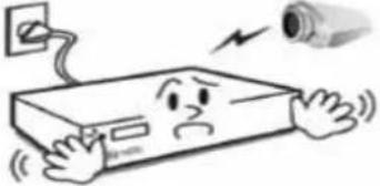 |
Keep the cables at least 15 centimeters away from the wall and at least five centimeters away from the side so that the cables, including power line and video c disfigured. Otherwise it might put you at the risk of fire, electrocution and damage. | Never uplift the cover, break down, repair and maintain at your disposal. Otherwise it might put you at the risk of fire, electrocution a damage. may not be |
Keep the device environment always clean before and after installation of the device. Use dry cloth to clean the device. Ne organic solvent. Otherwise it might be the cause of electrocution or mechanic disorder. | Input voltage of the device should come within the range of 10 percent of specified voltage. Use separate wall power to keep heating appliances, including hair dryer, iron and refrigerator. Otherwise it might be the cause of fire and electrocution. |
| When strange noise or smell is sensed, immediately plug out and send inquiry to service center or seller. | Do not install device in humid place filled with dust. It might be the cause of electrocution and fire. |
 |  |
| Caution | |
Do not install the device in any place where strong magnetic flow, electric wavelength and vibration may be sensed or where radio, TV or other wireless device is located. Keep the device away from magnetic flow, electric wave or vibration. | Do not put anything heavy on otherwise it may be the cause of disorder. TV or  |
Strong shockwave or vibration may be the cause of mechanic disorder. Please be careful. | Be careful so that anything conductive may not fall into the ventilation hole. Otherwise it may be the cause of disorder. |
Check if power switch and record on the front side of the product is still turned on. | When HDD is overloaded, you change the setting to keep recording. In that case, check again if it would be OK to eliminate the saved data. |
When HDD saving data gets old enough, video data to be saved may suffer so much damage that it may be irreparable. If s broken while regenerating data saved it means HDD won't work any longer. Immediately contact service center to replace them.

natural_image
Cartoon illustration of a person using a tool to interact with a large cylindrical object (no text or symbols present)When any abnormal sign is detected, immediately contact seller or service center. creen appears in HDD,

natural_image
Cartoon illustration of a smiling worker holding a tool, next to a smiling rectangular object (no text or symbols)Caution : Any changes or modifications in construction of this device which are not expressly
Approved by the party responsible for compliance could void the user's authority to operate the equipment.
Note : This Equipment has been tested and found to comply with the limits for a Class A digital A digital device, pursuant to part 15 of the FCC Rules. These limits are designed to provide reasonable protection against harmful interference when the equipment is operated in a commercial environment. This equipment generates, uses, and can radiate radio frequency energy and, if not installed and used in accordance with the instruction manual, may cause harmful interference to radio communications. Operation of this equipment in a residential area is likely to cause harmful interference in which case the user will be required to correct the interference at his own expense.
Warnig ;
This is a class A product. In a domestic environment this product may cause radio Interference in which case the user may be required to take adequate measures.
Check Components

flowchart
graph TD
    A["DVR"] --> B["Battery"]
    B --> C["Screw"]
    C --> D["Software CD"]
    E["Adaptor"] --> F["Power Cable"]
    G["Remote Controller"] --> H["Device"]
| Component 설 | 명 |
| DVR Stand Alone Digital Video Recorder | |
| Battery 1.5V (AAA) 2 pcs. | |
| Screw For HDD mounting | |
| Software CD Manual and Client program | |
| Adapter DC 12V | 6.67A |
| Power Cable Power cable | |
| Remote Controller For DVR operation | |
- Contents -
Chapter 1. Features & Components
1-1 Features....9
1-2 Name and function of front panel....10
1-3 Rear panel....11
1-4 Remote Controller....12
Chapter 2. Basic Information
2-1 Menu Display....13
2-2 Description of Icon....13
2-3 Remote Controller....15
2-4 How to set remote controller ID....16
2-5 How to display menu.... 17
2-6 Zoom In/Out 18
Chapter 3. System Configuration
3-1 Information....19
3-2 Time/Date....20
3-3 Password....21
3-4 Hard Disk....22
3-5 Default Setup....23
3-6 Upgrade....24
3-7 Button Setup....24
3-8 RS-485....25
Chapter 4. Display
4-1 OSD....25
4-2 Auto Sequence....26
4-3 Spot Out....26
4-4 Video Output Setup....27
Chapter 5. Network Setup
5-1 IP Address....28
5-2 Notification....29
5-3 Email Notification....30
5-4 Web Server....30
5-5 Free DDNS....31
DIGITAL VIDEO RECODER MANUAL
5-6 Dual Codec Setup....12
Chapter 6. Camera
6-1 Camera Title....33
6-2 PTZ Setting....33
6-3 How to use PTZ....35
Chapter 7. Record
7-1 Record Setting....37
7-2 Schedule Record....37
7-3 Holiday Record....38
Chapter 8. Event Setup
8-1 Sensor....39
8-2 Motion Detection....40
8-3 Event Action....41
Chapter 9. Search
9-1 Search Menu....43
9-2 Calendar Search....43
9-3 Date/Time Search....44
9-4 Event Search....45
9-5 Go to first/ Go to last....45
9-6 Search Control....46
9-7 Audio....46
Chapter 10. Backup
10-1 Backup....47
Chapter 11.Remote Connection – iPhone....52
Chapter 12.Remote Connection – Android Phone....61
Chapter 13. Specification....72
Chapter 1. Features & components
1-1. Features
The highly advanced and high-performance video recorder is designed to make it easier to install and use with safety.
Main feature
- Able to control the PTZ by using mouse like joystick
- Front USB port for easy backup
- Able to back up by ODD (optional)
• Support GIGA bit Ethernet. - Able to access internet with dynamic IP address
- Support Dual-Stream network transmission.
- Able to output simultaneously thru TV, VGA, S-VHS, Spot
- Able to set the resolution, frame and quality per channel.
• Support a number of PTZ protocol
• Support Central Monitoring Software (CMS).
Application Range
√ Banks, ATM machine, supermarket, convenience store and other places
√ residential area, apartment buildings, jewelry store, commercial building
√ places requiring safety for children such as school, elementary school and playground
√ warehouse, storage house and workplace
√ Places requiring remote surveillance
1-2. Name and Function of Front Panel

(Front Panel Image)
| No | Button/Function Description | ||
| 1 | Direction Button /Playback Button | Use as a control button on Setup menu | |
| Speed control on playback, Stop button, Pause button. | |||
| 2 | Menu Display a menu, Move to upper menu, Cancel a function | ||
| 3 | Pan/Tilt Display Pan/Tilt menu | ||
| 4 | Audio Display Audio listening menu | ||
| 5 | Backup Display Backup function of video data | ||
| 6 | Number Channel selection or number input | ||
| 7 | LED Status | Show status of Power, Recording, Remote Access, Schedule Recording and Emergency Recording | |
| 8 | Function Button | Search | Display search menu |
| Split Mode | Select split mode | ||
| Sequence | Automatic screen shift | ||
| Schedule Recording | Schedule recording | ||
| Emergency Recording | Emergency Recording | ||
| 9 | Front USB Port | USB Connecting slot | |
| 10 | ODD | Available to connect ODD | |
1-3. Rear Panel
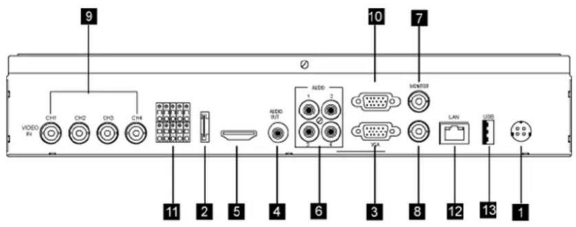
| No | Button/Function Description | |
| 1 | Power Power Input | |
| 2 | External SATA Port External storage and backup port | |
| 3 | VGA VGA Monitor Output | |
| 4 | Audio Out Audio Output | |
| 5 | HDMI Out HDMI Video output | |
| 6 | Audio Input Audio Input | |
| 7 | Video output CCTV Monitor Output | |
| 8 | SPOT | SPOT Output |
| 9 | Video Input | Camera Video Input |
| 10 | Serial Port | RS-232 Port |
| 11 | Tx, Rx, Sensor, Alarm | Pan/Tilt(Tx, Rx), Keyboard(Tx, Rx), Sensor Input, Alarm Output |
| 12 | Rear USB port | USB Connecting Slot |
| 13 | LAN port RJ-45 Ethernet Port |
1-4. Remote Controller

Chapter 2. Basic Information
2-1. Menu Display
It's available to make setup with menu button on front panel, a mouse and a remote
Display Setup Menu with a front panel button There are 'Menu' button on the front of unit. Press it to display Menu.
Display Setup Menu with a remote Press Menu button on a remote.
Display Setup Menu with a mouse Mouse right click to display pop-up menu. Select the menu you want to do setup.
2-2. Description of Icon
[1] The icons on the live screen indicate the status.


Recording

Video Loss

Motion Detection

Sensor
[2] Camea title will be shown as above.


[3] Status Bar
- Display date and time
- ER means Emergency Recording and SR means Schedule Recording.
- Show network status and key lock
- Show HDD status and display "Overwrite" when overwriting previous data.
2-3. Remote Controller
It is available to control every function with a remote. Controlling several DVRs with a remote is available..
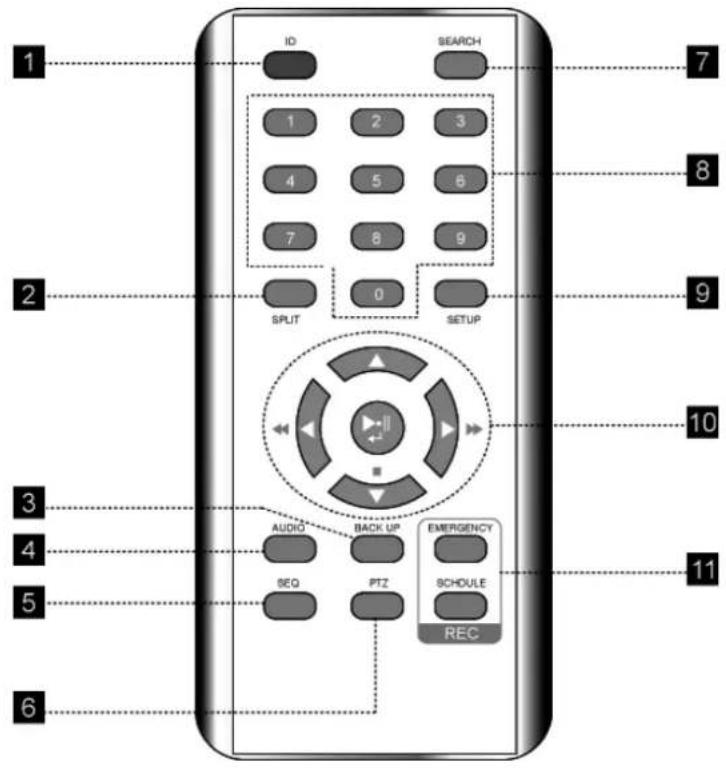
[1] ID : Press to select a remote controller ID in case of using one remote controller to multi DVRs.
[2] SPLIT : Press to see split mode. Once press. Same button with Quad button
[3] BACK UP : Press to start recorded data archiving to external media
[4] AUDIO : Select a audio channel
[5] SEQ : Press to display each camera in sequence for specific duration.
[6] PTZ : PTZ control menu...
[7] SEARCH : Call search menu to playback recording image.
[8] NUMBER BUTTON : Input the channel number to make full screen mode or the number in setup menu.
[9] SET UP : Press to display setup menu.
[10] DIRECTION KEY / CONFIRM BUTTON / PLAYBACK CONTROL
[11] Record Button
• EMERGENCY : Emergency Recording Button
• SCHEDULE : Schedule Recording Button
2-4. How to set remote controller ID
In order to use remote controller, the ID must be same both DVR and remote controller. assigning DVR ID, it allows the user to control multiple DVRs with one remote controller.

[1] Check current system ID and can be changed by user. (Factory default ID: "0")
Menu > System > Information > Remote ID (Range: 0 \~ 99)
System ID must be configured on DVR system menu. It cannot change DVR system on remote controller.
[2] How to use remote controller
ID must be identified between remote controller and system. Otherwise remote controller doesn't recognize DVR correctly.
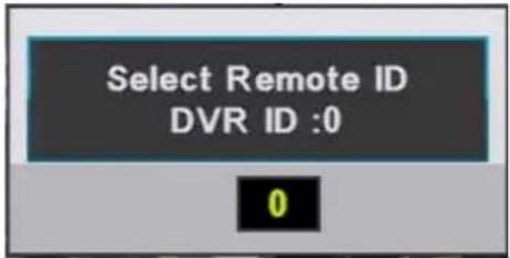
Remote controller ID menu displays as above image when you press ID button of remote controller.
• DVR ID : It displays current ID of the system.
- "0": Input the same ID number of DVR and press "Confirm"
2-5. How to display menu
It is available to display menu with front panel buttons, remote and mouse.
[1] Front panel button : Push "MENU" button on the front panel.
[2] Mouse : Right-click
[3] Remote : Push "MENU" button

 | System | Go to main menu | ||
 | Search | Go to search menu | ||
 | Backup | Go to backup menu | ||
 | Audio Out | Go to audio output menu | ||
 | Emergency | Start emergency recording | ||
 | Schedule | Start schedule recording | ||
| [8GB7] | PTZ Control | Go to PTZ Control menu | ||
 | Sequence | Start sequence | ||
 | I/O | Switch output to Alarm or internal buzzer | ||
 | Split Mode | Change display split mode | ||
 | Zoom | Magnify the image at live or playback |
2-6. Zoom in/Out
Magnify the image at live or playback.
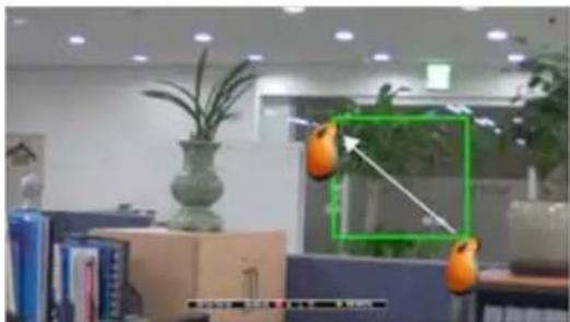
[1] How to magnify with a mouse
Locate the mouse pointer on the place you want to magnify. And click the left button of mouse and drag it. You can cancel by dragging with mouse left button clicked. (Also you may use "Zoom In / Zoom Out" menu by displaying menu)
natural_image
Interior office scene with a potted plant, stacked boxes, and orange objects (no visible text or symbols)[2] How to magnify with a remote (Front panel button)
- On Live : Display Menu and select "Zoom In/ Zoom Out". And move with direction buttons. Select Menu button to cancel
- On playback: Select "Emergency Recording" and move with direction buttons. Select Menu" to cancel.
Chapter 3. System Configuration
3- 1. Information

[1] Remote ID : Assign the ID of remote controller, so that user can separately control multiple DVR unit with one controller. (ID range: 0 \~ 99)
[2] Mouse Resolution : Mouse sensitivity level can be adjusted at user's convenience. (Basic Level 1; Slow speed, Level 1 < Level 2 < Level 3 to increase reaction speed.)
[3] Language : Select a language
[4] Vertion : Show S/W, H/W and N/W
[5] Health : Indicates storage status
- Hard Disk 1\~3 : Display the temperature of hard disk
• E-SATA : Display the temperature of hard disk connected to E-SATA
- Board : Display the temperature of the DVR's main board.
[6] Video Detect Mode : Select a video signal format. (NTSC / PAL)
[7] Video Mode : Display video signal format
[8] WEB Code : DDNS ID for DDNS connection.
[9] MAC Address
3-2. Time/Date

[1] Time : Set time
[2] Date : Set date
[3] Date format : Select a Time/Date display format.
[4] Daylight Saving Time : Set "ON" to apply daylight saving time.

Enter Month/Week/Day to begin and also enter Month/Week/Day to end.
[5] Time Server : Set time automatically through internet.
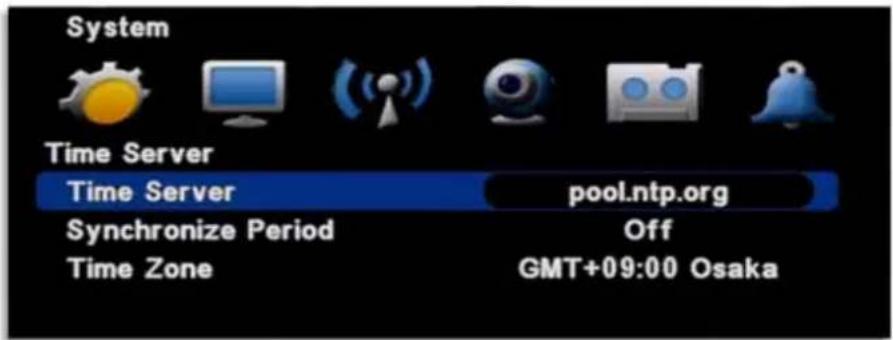
- Time server : Input the URL of server (Default : kr.pool.ntp.org)
- Synchronize Period : Select the period to synchronize between DVR and time server
• Power On : Try to sync once power on.
• 12Hour : Try to sync every 12 hours.
• 24Hour : Try to sync every 24 hours.
• Time Zone : Select Standard time
[6] Apply : Save and apply time / date setting.
3-3. Password

[1] ID : Available to register max 8 account("Admin" and "User1\~7")
• admin : Administrator ID
- User1\~7 : User ID
[Note] Default password of all ID is "11111111".
[2] Assign an authority per selected ID
-
Configuration : Available to set configuration
• Hard Disk : Available to set Hard Disk
• Search : Available to search -
Backup : Available to back up
• PTZ Setting : PTZ operation is available
• PTZ OSD Menu : Assign an authority to display PTZ OSD menu - Record Key: Assign an authority to use "REC" on the front
• Camera : Available to see the selected channel
3-4. Hard Disk
As it is related to recording, if any setting is wrong, system error or abnormal recording could happen.

[1] Hard Disk List: It provides the information for Hard Disk, external USB Hard Disk and format.

- Hard Disk 1\~3 : Display the Hard disk capacity internally mounted
• E-SATA : Display the capacity of E-SATA - Delete : Select a disk and format(delete) it
[2] Total : Display total capacity and used capacity of Hard Disk
[3] Over write : Record continuously by overwriting the hard disk
[4] Erase Data : Format several hard disks altogether.
- Main Disk : Format all the mounted disks named "Main disk"
- Mirror Disk : Format all the mounted disks named "Mirror Disk"
[5] Auto Delete : Keep the recorded data for the selected period and automatically delete the previous data.
[6] Advanced : Select whether a Hard Disk is used as Main disk or Mirror disk.
- Hard Disk 1\~3 : Select with which purpose it will be used.
• E-SATA : Select with which purpose it will be used. - Apply : Save the setting
[Note] After setting, select "Apply" to save. Then, the system is rebooted.
3-5. Default Setup
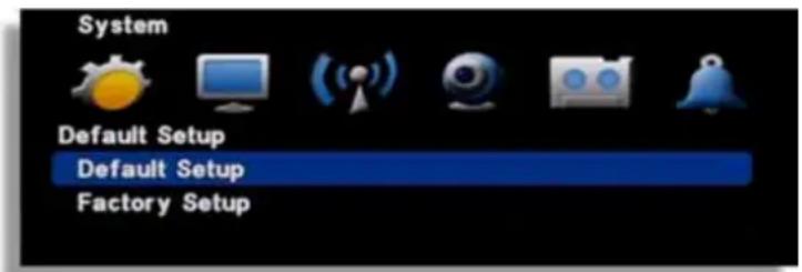
[1] Default Setup : Except major configuration (Network, Password), parameters are initialized.
[2] Factory Setup : All parameters are initialized.
3-6. Upgrade

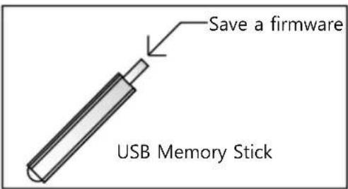
[1] USB (Firmware Upgrade): In order to upgrade system firmware with USB memory stick, the firmware file must be saved in the USB storage first and then insert to DVR to start USB upgrade from the menu.
[Note]
Do not turn off power or remove USB stick while the upgrade is in progress.
[2] Configuration Backup : Save a configuration file of DVR.
[3] Configuration Load : Upload a configuration file to DVR.
3-7. Button Setup
After a certain time passes, screen is automatically locked.
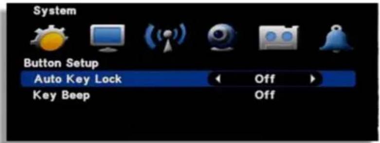
- Auto key lock: There is no key input during specific time, system locks the button automatically. In order to unlock, input the password. (10 sec. 30 sec. 1 min. OFF)
• Key Beep : If you select ON, beep sound occurs
3-8. RS-485
In order to control the PTZ camera or control keyboard, DVR supports RS-485 port.

Baudrate /Parity /Stopbit : Refer to the manual of "Keyboard" or "PTZ camera"

Chapter 4. Display

4-1. OSD (On Screen Display)

[1] Camera Title : ON / OFF
[2] Status Bar : ON / OFF.
[3] Login Display : Select a login option
- As Per Last Login : Display live image after system rebooting.
- Cover All Camera : Do not display live image after system rebooting.
[4] Login menu: Select a log in option.
• Always from boot : Input the password after rebooting.
- Boot after lock: Auto login after rebooting.
4-2. Auto sequence

- Auto Loss Skip : If there is no video input, it skip video loss channel.
- Display time: Select a display duration while sequencing (1 sec. \~30 sec.)
[Note] Sequence doesn't work on event pop-up.
4-3. Spot Out
Control extra spot output on rear panel. By using additional monitor, event triggered video display and sequence display are available.

[1] Mode
- Sequence : Display videos in selected time order per channel.
• Event : Display event triggered channel. - Seq+Event : If an event is triggered, the video is displayed first and then videos displays in sequence.
[2] Display Time : Set time per channel applied in sequence display.
4-4. Video Output Setup
You can choose a type of video output. This model supports HMDI, VGA and composite output.

[1] Video Output Setup
- HDMI+VGA(S) : Set HDMI as main output and VGA as Spot Out.
- VGA+Composite(S) : Set VGA as main output and Composite as Spot Out..
- HDMI+Composite(S) : Set HDMI as main output and Composite as Spot Out..
[2] Vga Resolution : Select a resolution for VGA out.
(Resolution : 1920*1080 , 1440*900 , 1366*768 , 1280*1024, 1280*720 , 1024*768 )
NOTE : HDMI out is fixed at 1920 x 1080 and it is not able to video out with \simtaneously.
Chapter 5. Network Setup

5-1. IP Address
It is the system setup for remote monitoring or backup and it needs the network setup of DVR. The user must know whether their internet is dynamic IP(DHCP) or fixed IP. Please check it to your ISP before setup.
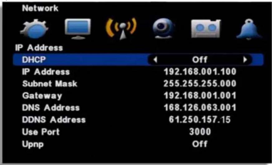
[1] DHCP : "ON" for dynamic IP user. "OFF" for static IP user.
[2] IP Address : Input the IP address.
[Example]
• IP address : 61.250.152.050
- Subnet Mask : 255.255.255.000
• Gateway : 61.250.152.001
• DNS Address : 164.124.101.002
[3] DDNS Address : Do not change the DDNS server IP (61.250.157.15)
[4] Use Port : Default port is 3000.
[5] Upnp : If a router supports Upnp, it automatically set port forwarding.
[NOTE] In case of using the router, the user should make port forwarding. The port forwarding function is described on the router manual.
5-2. Notification
E-Mail Setup
It's a basic setup to send E-mail, so if it is not correct, e-mail couldn't be delivered. So be careful to make Setup correctly.

[1] SMTP Server : Enter Mail Server address to use as SMTP Server. If you don't know the Server address, contact a person who manages SMTP Server you use.
[2] Mail From: Enter the mail address which you use. (It is for preventing a mail blocked as spam.)
[3] Mail Address: Enter recipient's mail address (Available up to 3 account)
[4] Password : Select if ID/Password input is necessary when sending a mail.
[5] Use Port: Most of Mail Servers use 25 for port. Check Port if system doesn't work after setting.
5-3. E-mail Notification
Select which type of notifications you are going to use.

Notification type : You can select the type for E-mail notification.
- Alarm: E-mail is sent with still image when an alarm occurs
- Sensor : E-mail is sent with still image when triggering a sensor
- Motion Detection : E-mail is sent with still image when detecting a motion.
• Video Loss : E-mail is sent when video input is lost.
• Power On : E-mail is sent when power is on after off. - Password Modify : E-mail is sent when the system password is modified
• HDD Error : E-mail is sent when HDD error happens
5-4. Web Server
Built-in web server make user can connect the DVR remotely on the Internet Explorer

[1] ON/OFF : Select 'ON' to use remote N/W connection through web.
[2] USE PORT : Port for remote connection
5-5.Free DDNS
Free DDNS is used for remote connection through private DDNS service.
Firstly, go to http://www.dyndns.com and create an account. Then, if your system is installed with a router, you must make DMZ setting in the router setup for the IP your system has.
DMZ is a function to open all the ports for the selected IP.
Input registered information in DVR setup.
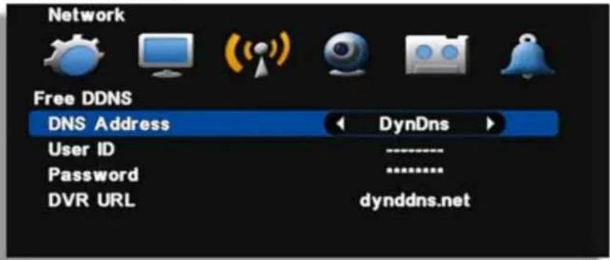
- DDNS address : Select the private DNS service name (Select DyDns)
- User name/ Password/ DVR Address : After creating an account in the relevant website, input the ID/ Password/ URL information allocated to DVR setup.
5-6. Dual Codec Setup
It is a transmitting function through the extra network transmitting Codec. The setting on the white box below is the transmission setting for split screen and the setting on the bottom is for one full channel.
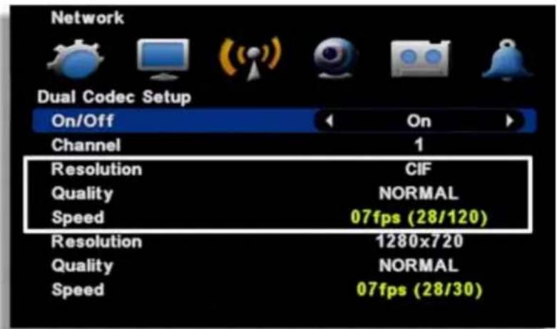
- On/ Off: If you want to use it, set ON.
- Channel : Select the channel to set (Available to set per channel)
- Resolution : Select the resolution to transmit (Fixed with CIF at split screen transmission)
• Quality : Select the picture quality to transmit - Speed : Select the frame to transmit
- Total Rec Frame rate : Available to allocate per channel within 120FPS (total transmitting speed)

Chapter 6. Camera

6-1. Camera Title
Input a camera title using by virtual keyboard.
![Camera Camera Title CH1 1 2 3 4 5 6 7 8 9 0 - = \ < Tab q w e r t y u i o p [ ] / Caps a s d f g h j k l ; ' Enter Shift z x c v b n m , . / Space English Alt](/content/2026/05/1081311/images/5fe16ae7cc8dab955ec7d3054d3b929d1158ced01518043d4cae768ae2eadcf8.jpg)
Press a space bar to change a language.
6-2. PTZ Setting
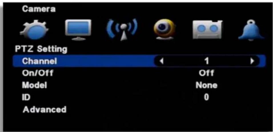
[1] Channel: Select a channel
[2] ON/OFF : Enable or disable to use PTZ.
[3] MODEL : Select the PTZ protocol or, model
[4] ID : Select the PTZ ID. (For more detail, refer to the manual of PTZ device.)
Advanced
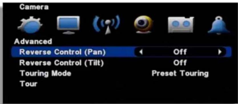
[1] Reverse Control (Pan) : Set the Pan works reverse direction.
[2] Reverse Control (Tilt): Set the Tilt works reverse direction.
[3] Touring Mode
- Preset Touring : Use touring by DVR setting.
- Camera Touring : Use touring by camera setting. (PTZ camera built-in touring function is available only.)
[4] Setup Preset Touring
It is operable when you select the 'preset touring' from the touring mode' menu.
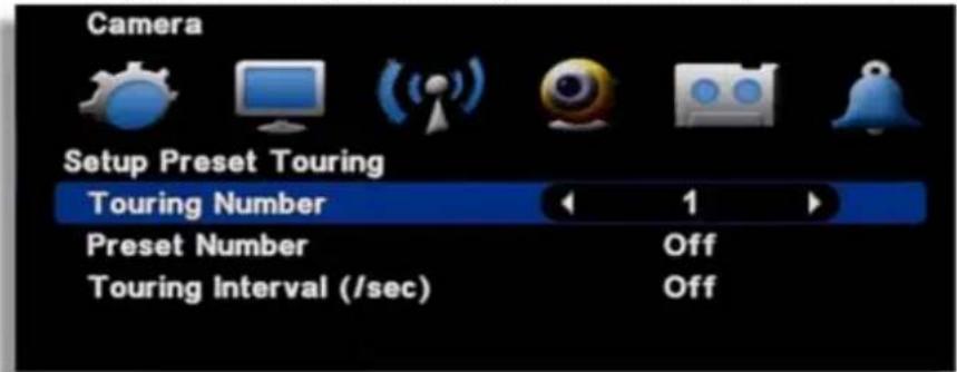
The touring number is selectable 1\~16.
[1] Touring number : Select the number.
[2] Preset number : Select the preset number saved before.
[3] Touring interval (/SEC): Select the touring dwell time.
[NOTE] PTZ protocol selection
Protocol is PTZ moving driver. The protocol is registered as per the camera model name or protocol name. Please check whether you PTZ is usable for this DVR. The touring is supporting when the camera itself support the touring function.
6-3. How to use PTZ
[How to call the PTZ menu]
- Mouse menu: Click the right button of mouse and select the 'PTZ'.
- Remote controller menu: Click the "PTZ" from remote controller.
(1) Select PTZ Button on the remote controller
![KT&C K9-s400 - [How to call the PTZ menu] - 1](/content/2026/05/1081311/images/b68e7e980d29e123170672d60c8aaecf67489f69ead2580bd81412c0c123231d.jpg)
natural_image
Interior view of an office with potted plants and ceiling lights (no visible text or symbols)- When you select PTZ button, + shape icon appear. Then move to the channel you want by the direction key.
(2) If you moved to PTZ channel, then after pushing "SET UP" button, select the menu to operate.

- PanTilt : Control the direction by the direction key in remote controller.
![KT&C K9-s400 - [How to call the PTZ menu] - 3](/content/2026/05/1081311/images/4c1bf01f84c1deb70c29df2bdafb365f004b40bfc2b3904a0f96ce2dacadbfda.jpg)
- Preset : Input the preset number to be moved or saved and select this menu.

(Preset moving)
![KT&C K9-s400 - [How to call the PTZ menu] - 5](/content/2026/05/1081311/images/91d43d355af3755cd096c6b19b2447f1a01efaee1a6ae6ee6fb75bb8104dbbe4.jpg)
(프리셋 저장)
• Tour : It tours as per the saved preset number.
![KT&C K9-s400 - [How to call the PTZ menu] - 6](/content/2026/05/1081311/images/42486db7fbd2cb863fdc89e05d315dfc153ebfd99e6a6bab8f5d2a737247113d.jpg)
Tour
- MENU : It can recalls the PTZ camera OSD menu

Menu
- Channel : Change channel at split screen. Available to move with direction button after selecting a channel. (Only work on split screen)

Channel
• Auto Focus : Adjust the focus automatically.

AutoFocus
- Exit: Escaping the PTZ mode

Exit
Chapter 7. Record

7-1. Record Setting
Set resolution, quality, recording speed and audio. Each setting affects the size and picture quality.

[1] Channel : Set channel
[2] On/Off : Set On or Off for recording
[3] Resolution : Set resolutioin
[4] Quality : Set picture quality of recorded video
[5] Speed : Set record frame
[6] Post-Recording : Set recording duration time after an event is triggered.
[7] Record Audio : Set On or Off for audio recording
7-2. Schedule Record
Set schedule record per day of the week, time and channel. And setting per hour is also available.

N (Grey) : No record
C (Green) : Continuous record
M (Blue) : Motion detected record
S (Red) : Sensor triggered record
M+S (Yellow) : Recording by motion detection or sensor triggering
[How to setup]
- Select a channel
- After selecting the day of the week and time, every mouse click makes color shift like N(Grey) → C(Green) → M(Blue) → S(Red) → M+S(Yellow)
• After selecting the other day of the week and time, every OK button click makes color shift.
• Clear : Delect the schedule of the selected channel - Channel Copy : Copy the currently set recording schedule to the selected channel.
- All Ch to Copy : Copy the currently set recording schedule to all channels.
7-3. Holiday Record
Set holiday record with different option.
[1] 7 different holiday setup can be made.
After selecting record type from H1 to H7, set time with mouse dragging or remote direction key.

[2] Select the Holiday on Holiday Calendar and then set the holiday type among H1 to H7.

Every mouse click on the selected date makes color shift and available to set from H1 to H7.

Chapter 8. Event Setup
8-1. Sensor
It is for sensor setup.

[1] Sensor Input: Select the sensor input channel.
[2] On/Off: Select the sensor usage.
[3] Input Type: Select the sensor input type.
- N/Open (NORMAL OPEN): The contact is normally opened but close when the signal is generated.
- N/Close (NORMAL CLOSE): The contact is normally closed but open when the signal is generated.
[4] Related camera: Select the camera to be related with sensor. Multi-selection is possible.
8-2. Motion Detection
It is the motion detection setup menu.

[1] Channel : Select the motion detection channel.
[2] On/Off : Select the motion detection usage.
[3] Sensitivity : Select the sensitivity of motion detection. Please apply it after the actual testing.
[4] Detection Area: Select the motion detection area. (1\~5)

natural_image
Interior view of a modern office or service center with large windows, green plants, and a digital display board (no visible text or symbols)The cursor moving by the direction key and if press "enter", this block is designated for motion detection.
• MD selected area : Pink color
• MD non-selected area : Transparent
- If the movement is detected, the color of that area turns green.
[ Apply to all ] If you use the following key, you can apply or release in one button
"No1" button: Release all
"No 2" button: Select all.
[Using mouse]
Locate the pointer on start point and click the right button then dragging to the ending point.
8-3. EVENT ACTION
Event record will be made as per the setup.
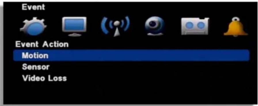
[1] Motion : It is the setup for PTZ, pop-up, relay out, buzzer in motion detection.

- Channel : Select the channel to apply.
- Preset channel: Select the preset camera being applied for the event.
- Preset number : Select the preset number to move.
- Popup Channel : Select the usage Popup usage by ON/OFF.
- Popup Duration : Popup window floating time.
- Relay out: Select the alarm out
- Relay duration : Relay out duration.
- Internal buzzer : Internal buzzer usage.
[2] Sensor : It is the setup for PTZ, pop-up, relay out, buzzer in sensor triggering.

• Channel : Select the channel to apply.
- Preset channel : Select the preset camera being applied for the event.
- Preset number : Select the preset number to move.
- Popup Channel : Select the usage Popup usage by ON/OFF.
- Popup Duration : Popup window floating time.
- Relay out: Select the alarm out
- Relay duration : Relay out duration.
- Internal buzzer : Internal buzzer usage.
[3] Video loss : It is the setup for PTZ, pop-up, relay out, buzzer in video loss.
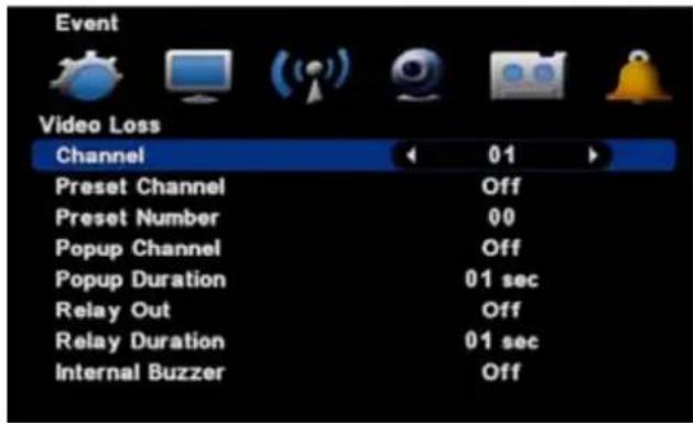
• • Channel : Select the channel to apply.
- Preset channel : Select the preset camera being applied for the event.
- Preset number : Select the preset number to move.
- Popup Channel : Select the usage Popup usage by ON/OFF.
- Popup Duration : Popup window floating time.
- Relay out: Select the alarm out
- Relay duration : Relay out duration.
- Internal buzzer : Internal buzzer usage.

Chapter 9. Search

9-1. Search menu
It supports the various ways of search mode such as Calendar, Date/Time, Event, etc.
[1] How to call menu: Select the "SEARCH" from remote controller and right button of mouse.
[2] Search mode selection

- Calendar search: It searches by calendar.
- Date /Time search: It searches specific Date/Time.
• Event search: It searches as per the event. - Go to first: It searches the first recorded data on HDD.
- Go to last : It searches the last recorded data on HDD.
9-2. Calendar search
It searches using by the calendar.
[1] If there is the recorded data on DVR, it shows red color on recorded date. Using the direction key, you can change the YEAR/MONTH/DATE.

[2] If there is the recorded data, it shows red color so, press the enter button on selected date.
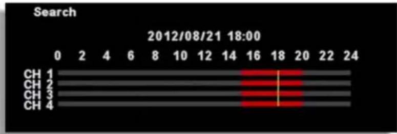
bar
Search | Channel | Value | |---|---| | CH 1 | 18 | | CH 2 | 18 | | CH 3 | 18 | | CH 4 | 18 |(Channel display could be different per model 4ch/8ch/16ch)
[3] The recorded data shows as a graph and select the minutes to search.

bar
Search 2012/08/21 18:15 | Category | N | C | M | S | M+S | |---|---|---|---|---|---| | CH 1 | 0 | 0 | 60 | 0 | 0 | | CH 2 | 0 | 0 | 60 | 0 | 0 | | CH 3 | 0 | 0 | 60 | 0 | 0 | | CH 4 | 0 | 0 | 60 | 0 | 0 |(Channel display could be different per model 4ch/8ch/16ch)
9-3. Date/Time search
If you know the specific date/ Time, input the time to search.
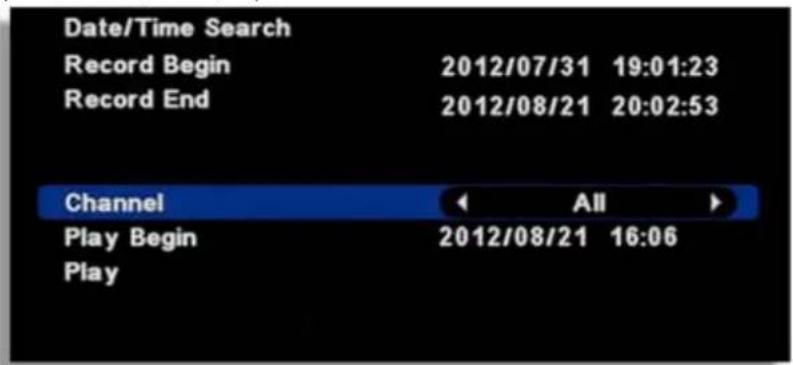
[1] Record begin: It shows the record began time.
[2] Record end: It shows the record end time.
[3] Channel : Select the channel to search.
[4] Play Begin : Input the time to search.
[5] Play : If you click "Play", it playback the selected time.
9-4. Event search
It searches event recorded data.

[1] Record begin: It shows the record began time.
[2] Record end : It shows the record end time.
[3] Channel : Select the channel to search.
[4] Play Begin : Input the time to search.
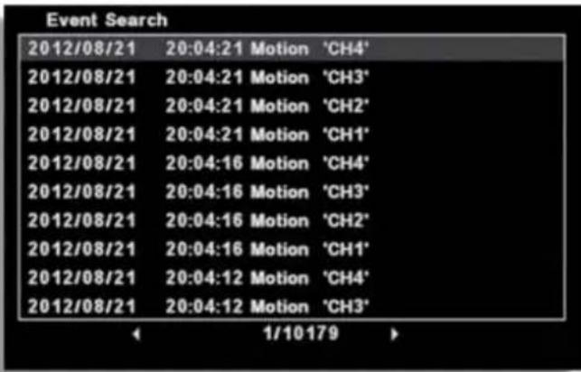
[5] Play : If you click "Play", it playback the selected time.
9-5. Go to first / Go to last
It searches the first or last recorded image.
9-6. Search Control
[Control by mouse]
Description of search button

[1] X1 playback
[2] Pause
[3] Stop
[4] Reverse playback
[5] Playback speed control
[6] Reverse playback speed control
[7] Audio during playback
[8] Calendar search during playback
[9] Mark In-Mark Out: If you click it during playback, it recognizes as a backup start time and if you click it once again, it recognizes as a backup end time. After this, it moves to the backup menu automatically.
[10] Screen magnifying function in the full screen. (Use Emergency recording button on the remote controller.)
[Control by Remote control]
Use the direction from the remote control to control the speed
9-7. Audio
Audio can be listened in Live or Search.

[1] Menu recall: If you select the "AUDIO" during the live or playback, the audio out menu show up. The menu call is possible by remote controller or mouse.
[2] Mode selection
- OFF: No audio use.
• CH1 : Audio out only from CH1
• CH2 : Audio out only from CH2
• CH3 : Audio out only from CH3
• CH4 : Audio out only from CH4
• Auto : Only selected channel audio out.
• Volume control : If the length of bar increase, the volume louder.

Chapter 10. Backup
10-1. Backup
Selected image can be backup to the external device(USB). Connect the USB pen drive to the DVR and select 'BACKUP' button from remote controller or, click the right button of mouse.
[1] Select the recognized backup device. If it recognized normal, it shows the device capacity such as "XXX MB".

[2] Select the date from Calendar.
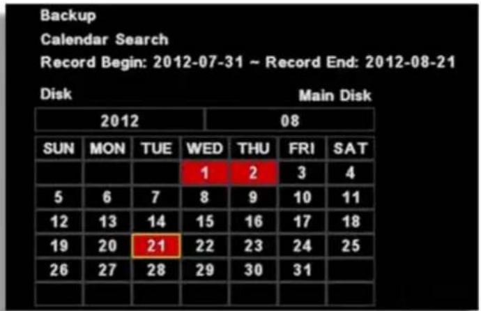
[3] Select the time by double click.

(Channel display could be different per model 4ch/8ch/16ch)
[4] Select the minute. Once you select "Start", the time will be automatically input.

bar
Backup | Channel | Backup Start (0-60) | Backup Start (10-20) | Backup Start (20-30) | Backup Start (30-40) | Backup Start (40-50) | Backup Start (50-60) | | :--- | :--- | :--- | :--- | :--- | :--- | :--- | | CH 1 | 0 | 10 | 20 | 30 | 40 | 50 | | CH 2 | 0 | 10 | 20 | 30 | 40 | 50 | | CH 3 | 0 | 10 | 20 | 30 | 40 | 50 | | CH 4 | 0 | 10 | 20 | 30 | 40 | 50 | Camera A 1 2 3 4 2012/08/21 16:03 End Backup Start[5] Backup end time selection
- If the backup end time is the same hour, select the minute and click, "end", the time will be automatically input.
- If the backup end time is the different hour, go back to the previous menu by right button of mouse or, "MENU" button. Then, select the hour/minutes and click "end" for automatic time input.
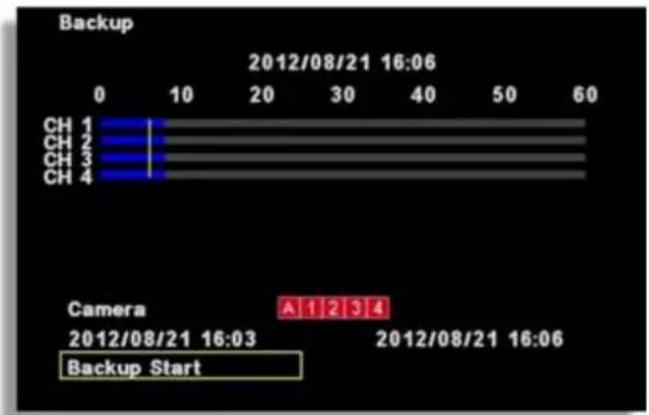
[6] Camera : Select the channel to be backup.( Selected channel will be shown as red)
[7] Backup Start : If all setup is completed, click the 'Backup start' button then, backup starts. It shows the backup capacity/ USB pen drive capacity" so, if everything is OK, click 'OK'.

[8] Before backup, it shows the USB port, backup time then, select OPTION.

- Log Backup: The log file will be backup together.
- Password : Backup data can be protected by the password.
- Format Backup Disk : Select whether the viewer program will be backup together with data file.
- Executable format : Viewer program will b backup together
- Video Format : Only data file will be backup without viewer program
[9] Backup Start: The backup start after click 'OK'

[10] If the backup is completed, you will see the below icon as a file in USB stick. If you click it, playback starts.

201011241126_0 MS BackupViewer
[11] How to use the viewer program( If you click the backup file, it runs automatically).

DIGITAL VIDEO RECODER MANUAL
① Scroll bar : It shows the current location from the total playback volume.
② Open : To open the other backup file.
③ Fast reverse playback
④ Reverse playback
⑤ One step reverse playback
⑥ Pause
⑦ One step playback
⑧ Playback
⑨ Fast playback
⑩ 4 split screen
⑪ 9 split screen
⑫ 16 split screen
⑬ Current image capture
⑭ When you convert it to AVI. You can click the 'START' and 'END' time(circled space) during playback and if you click 'AVI', it converts to 'AVI' file.
⑮ If you click it, you can listen to the recorded audio of selected channel.
11. Mobile Viewing by iPhone

11-1 Install the program
Go to Apple Store website and search and download MPRMS. Then install the MPRMS.
11-2 Execute the program
When the installation is completed, the following icon is created.
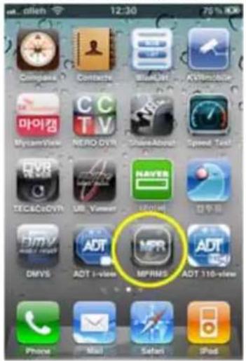
Select the icon to execute.
11-3 Register the product information
Enter the network information to access the DVR with iPhone.
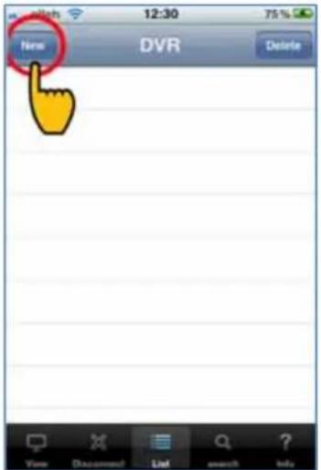
[1] Register
Execute the program in iPhone and click "New" for the new registration.
[2] Enter the Reg Name.

Any name is available to use for Reg. Name.
[3] Select the model name

If the item to be connected is a DVR, select DVR.
[4] Enter the DVR ID and Password.
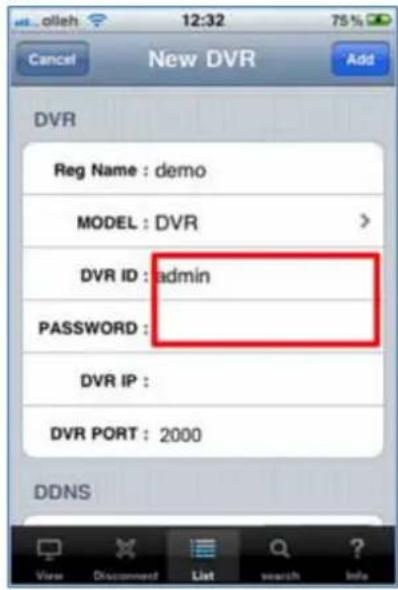
◎ DVR ID : Enter the ID registered in the DVR
◎ Password : Enter the password registered in the DVR
(Note : You can check the ID and password in the DVR Setup Menu)
[5] Enter the DVR IP (Static IP user only)
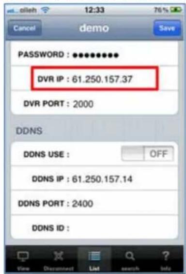
Dynamic IP user doesn't enter the DVR IP.
(Note) The static IP indicates the IP address registered in DVR.
[6] Set DDNS IP (Dynamic IP user only)

◎ Static IP user selects "OFF".
DDNS USE :

◎ Dynamic IP user selects "ON"
DDNS USE :

© DDNS ID : Enter the DVR's unique "Web code".
(Note : Keep the DDNS IP and DDNS PORT at their default value.)
[7] Set DDNS IP (Dynamic IP user only)

After setting all, press "ADD" to save.
11-4 Live monitoring
[1] Click the registered "DVR Name".
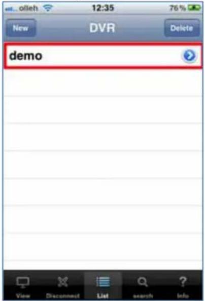
[2] Connect remotely
![2011 06:14 12:36:29 LIVE [360*240] 03F 1 2 3 4 5 6 7 8 9 10 11 12 13 14 15 16 I Frame Only : OFF View Discontinued List search Info](/content/2026/05/1081311/images/9c9c6ed031032fcdb84de0c3762c83c1af104776734e1ef8184c5f147b3db829.jpg)

For a channel selection, click "CH SELECT" to select a number.

< "PTZ" to control Pan/Tilt/Zoom
Off the information such as time, resolution, channel, etc. and display the video only.

When selected, it transmits still images with certain intervals in case video streaming is interrupted due to the network load.
See full screen: If you turn iPhone to one side, it's switched to full screen. (Touch any part of the full screen to call the menu)
11-5 Search
Select "search" the icon below.

[1] Select Date/Time

After selecting a date, select "SEARCH".
[2] Search key operation
![2011-08-04 16:37:04 dense Chg [20] 240] 03F SEARCH [ > ] LIVE View Disconnect List search Info](/content/2026/05/1081311/images/67d6515cfa30ebb0c1b5a619de2ef73ad6c3c2330dbc7db89fe8c199821e93e6.jpg)

Play reverse

Pause

Play

Switch to Live
11-6 Relay out
Relay can be controlled remotely..
![股价1.00 28 3.00 ChJ LIVE [360*240] DIF Sec 10sec 20sec 3min 50 Min 3min 10min 10min Hour 3hour Off Activity no miss View Disconnected List search Info](/content/2026/05/1081311/images/e2f9d0baf05c15f2c285d7b95be7a6e766f5613451504a465204a668d0bac78c.jpg)
Time selection : Set the duration time of alarm output
Off : Alarm off
Infinity : Keep the alarm output continued
11-7 PTZ control
PTZ control is available on iPhone. The way how to control is the same with on CMS and DVR
![2011 08:34 17:06:18 LIVE [360*240] OK ON CANCEL FOCUS PTZ HOME + - ZOOM + - Auto Focus DBD On Preset Help off View Disconnect List search Info](/content/2026/05/1081311/images/ce58bc0205f96de98ac29fa49219e524ae19c11599e87f65664592e5992ae3d3.jpg)

(1) Select
(2) Cancel
(3) Automatic camera focus
(4) Call the PTZ menu
(5) Direction button
(6) Camera focus control
(7) Camera zoom control
(8) Select the channel
(9) Relay out button (A user can set relay out)
(10) Select the PTZ menu
(11) OSD display On/Off button for live screen
12. Mobile Viewing by Andriod phone

12-1 Install the program
To install the program on the Phone, execute the 'MARKET' program and download the 'MPRMS' to install. If the installation is completed, you will see the 'MPRMS' icon on the main SCREEN.
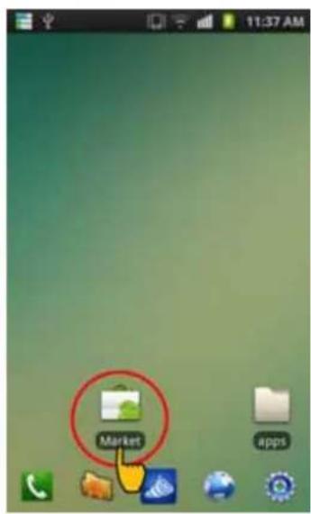
(1)
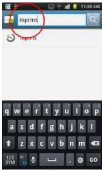
(2)

(3)
12-2 Execute program
Select "MPRMS" to execute the program.
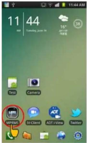
(Select the icon)
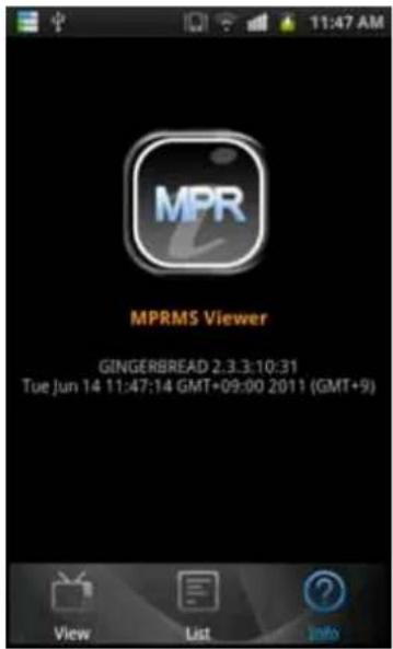
(Executed Program)
12-3 Register the product information
Register the product information for remote monitoring.
[1] Register

Select "Add" to start the registration.
[2] Enter the registration information

(1)

(2)

(3)
(1) Enter the name, Product ID(User) and Password.
Name : Enter any name you want.
User : Enter the "User ID" registered to the DVR.
Password : Enter the "Password" registered to the DVR.
(Note: "Menu" → "System" → "Password")
IP : This setting is only for static IP users.
(2) After selecting "DDNS use", enter the "Password, IP and Port".
(Note: Dynamic IP user only)
(3) You can check the DDNS ID from the DVR menu: 'Menu' → "System" → System Information.
Copy the 'WEBCODE' and enter it to DDNS ID and save it. (DDNS PORT is automatically changed as per the Webcode of DVR.)
12-4 Modify/Delete of Registered Information
If you want to modify or delete the registered information, select the triangle-shaped icon.


Select to edit the registered info.

Select to delete the registered info.
Close TOOL menu (As a dual function, it ends the connection)
12-5 Remote connection
Select the registered list for connection. Once you click the registered device, it shows the brief information like the I^t picture below. If you click the red-colored background, de appears like the 2^nd picture. Click OK to execute the monitoring program.
![MPRMS dem [demo] 61,250,157,14:2400 Do you want to connect? Active : WIFI OK Cancel](/content/2026/05/1081311/images/33250b3b301be886fc18f0965df8a6d5c9f15bc4f747d79163fcc1da664f146c.jpg)
(Select the list)
![MPRMS —— demo Information [demo] 61.250.157.14:2400 Do you want to connect? Active: WIFI - mobile(UMTS) Info: web.sktelecom.com State: DISCONNECTED/DISCONNECTED Roaming: false - WIFI State: CONNECTED SSID: uptime_rnd2, BSSID: 00:08:9f.c1:fch64, MAC: D4:E8:B2:74:BF:D6, Supplicant state; COMPLETED, RSSI: -83, Link speed: 11, Net ID: 2 IP: 192.168.0.10 OK Cancel](/content/2026/05/1081311/images/5637a1ce727667889cb44c6c78df3e20bd3bceb295c152f11680ceac3c1c855c.jpg)
(Detailed info.)
12-6 Live
Live shows the images taken from each camera in real time.

(1) Number : The screen no. currently displayed is shown with bold white. If you select a channel, the channel is displayed with full screen. (The channel no. could be different per model.)
(2) OSD: You can turn on or off the display for channel no., date, time, event, etc
(3) I frame : It transmits still images with certain intervals in case video streaming is interrupted due to network load.
(4) Audio listening : If you select a channel, you can listen the audio.
12-7 Multi-screen
Live monitoring by 4 split multi-screen is available.
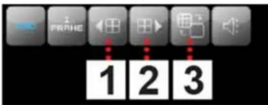
(1) Move to previous 4ch split screen.
(Ex) When monitoring 16ch DVR, split screen of CH1/2/3/4 is switched into CH13/14/15/16.
(2) Move to next 4ch split screen
(Ex) When monitoring 16ch DVR, split screen of CH1/2/3/4 is switched into CH5/6/7/8.
(3) You can change one channel into another during 4 split monitoring.
(Step)
1) When monitoring 1/2/3/4, if you want to change CH1 into CH6, select CH1 at first.
2) Then, the screen is switched into CH1 full screen. This time, if you select CH6, then the screen is switched into CH6 full screen.
3) If you click "Multi-icon" like picture, the screen is switched into split screen of CH6/2/3/4.
12-8 Main menu
On the bottom line of screen, there is a main menu. Select the menu to change the function


Go back to the previous step or close the monitoring program

Move to live mode (Channel change, 1 Frame and OSD display is available)

Go to PTZ mode

Go to PTZ preset mode

Go to search mode

Go to alarm mode

See the registered info.
12-9 PTZ
You can control the PTZ camera remotely.

(Select PTZ mode)

(PTZ mode screen)
(1) Go to PTZ mode
Select the PTZ connected channel and click the PTZ button.
(2) How to control PTZ

The PTZ camera moves to the selected direction.
Zoom in/ out

Focus adjustment


IRIS Open/ Close.

the PTZ menu

Auto Focus

OK button for PTZ OSD menu

Cancel or the upper menu on PTZ OSD menu
12-10 PTZ Preset
You can set the movement of PTZ camera previously and make the automatic PTZ movement.

(Select preset mode)

(Preset mode screen)
(1) How to go to PTZ mode
Select the PTZ connected channel and click the Preset button.
(2) How to operate Preset
- Move: If you select "Move" and press a number, then the camera moves.
- Save: If you select "Save" and press a number, then the current location is saved.
12-11 Search

(1. Select the search mode)

(2. Select "Time Search")

(3. Select the date and
(1) Select the search mode
(2) Select "Time Search": Select "Time Search" to enter the search conditions.
(Note: Select "To Live" to return to the live mode during the search.)
(3) Enter the date and time: Select the date and time and click "Start Search" for search.

Fast reverse playback

Reverse playback

ise

Playback

Fast playback
12-12 Relay Out
Relay can be controlled remotely.
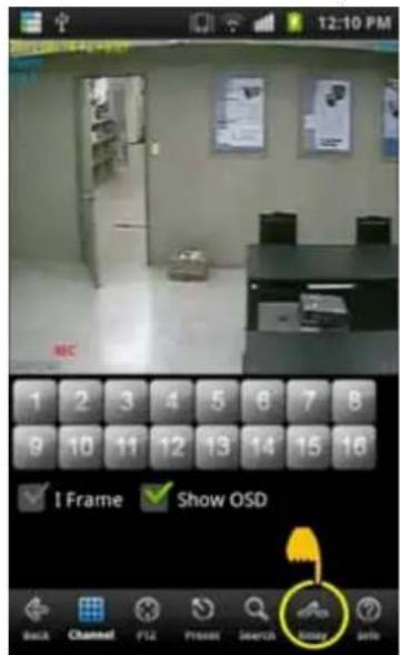
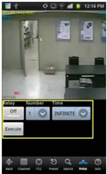
(1) Relay : Select On or Off
(2) Number : Select the relay number.
(3) Time : Select the duration time.
(4) Execute : Make the alarm output work
12-13 Information display
It shows the information of current connection.
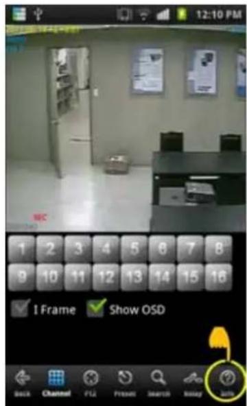
(Select info)

(Display the connection info)
[Display Info]
Below is the example for an explanation.
• IP : 61.250.157.37 : 2000 Via DDNS ← Connected IP information.
• MODEL : 16CH(63,xxx xxx:0) ← 16Ch model
- Webcode : H6F6057200001394 ← Product ID(Webcode).
• F/W : 84, N/W:21 ← F/W and network version.
• VSTD : NTSC ← VIDEO standard.
12-14 End the connection

(Select the back button)

(Select the Yes button)
There are several ways to finish the program.
- If you click 'BACK', it asks like "Do you want to disconnect?" Then, you may click Yes.
- Or you may just press close button on the phone.
| FDS-440SDI | ||
| Operating System Embedded Linux | ||
| Compression H.264 | ||
| Audio compression G723.1 | ||
| Video Standard NTSC / PAL | ||
| Video In/Out | Input 4Ch | |
| Output 1 x | HDMI / 1 x VGA / 1 x SPOT(BNC) | |
| Resolution | Max. 1920 x 1080 | |
| Split Mode in Live Display | 1, 4 | |
| Record Resolution 1080p C | camera: 1920*1080, 1920*540, 960*540 지원 | |
| 720p Camera: 1280*720, 1280*360, 640*360 지원 | ||
| Record Speed NTSC: 30fps@1080p per Channel / PAL: 25fps@1080p per Channel | ||
| Record Mode | Continuous, Schedule, Alarm, Motion, Emergency | |
| Search | Mode | Calendar, Date & Time, Event Search, First Search, Last Search, Backup Search |
| Speed | x1, x2, x4, x8, x16 | |
| Audio | In /Out | 4/1 |
| Sensor In / Alarm Out | 4/1 | |
| PORT | RS-232 External Keyboard controller & PTZ | |
| RS-485 | ||
| LAN | 10/100/1000 Base-Tx Ethernet (RJ-45) - Fixed IP, DHCP & DDNS | |
| Network Transmission | Video Dual-Stream (Local recording & Network Transmission) | |
| Remote Management | Built-in Web server (IE browser), iPhone, Blackberry, Android, Symbian, Windows Mobile | |
| Backup Device | Local Backup by USB Memory Stick and Network Backup by CMS | |
| HDD | (3 * SATA HDD & 1 * E-SATA HDD) or (2 * SATA HDD & 1 * E-SATA HDD & 1 * SATA ODD) | |
| Etc. | Multi-Language | |
| PTZ control by virtual joystick(operated by mouse) | ||
| Backup Viewer auto copy & AVI export | ||
| Power | Adaptor 12V 6.67A | |
| Operating Temp. | 0°C ~ 40°C | |
| Consumption Power | 16.5W | |
| Dimension | 358 mm(W) X 67mm(H) X 335mm(D) | |


- Before Usage
- Note of Caution
- - Contents -
- Chapter 1. Features & Components
- Chapter 2. Basic Information
- Chapter 3. System Configuration
- Chapter 4. Display
- Chapter 5. Network Setup
- Chapter 6. Camera
- Chapter 7. Record
- Chapter 8. Event Setup
- Chapter 9. Search
- Chapter 10. Backup
- 1-1. Features
- Main feature
- Application Range
- 1-2. Name and Function of Front Panel
- 2-1. Menu Display
- 2-2. Description of Icon
- 2-3. Remote Controller
- 2-4. How to set remote controller ID
- 2-5. How to display menu
- 2-6. Zoom in/Out
- 3- 1. Information
- 3-2. Time/Date
- 3-3. Password
- 3-4. Hard Disk
- 3-5. Default Setup
- 3-6. Upgrade
- [Note]
- 3-7. Button Setup
- 3-8. RS-485
- 4-1. OSD (On Screen Display)
- 4-2. Auto sequence
- 4-3. Spot Out
- 4-4. Video Output Setup
- 5-1. IP Address
- 5-2. Notification
- E-Mail Setup
- 5-3. E-mail Notification
- 5-4. Web Server
- 5-5.Free DDNS
- 5-6. Dual Codec Setup
- 6-1. Camera Title
- 6-2. PTZ Setting
- Advanced
- [NOTE] PTZ protocol selection
- 6-3. How to use PTZ
- [How to call the PTZ menu]
- Tour
- Menu
- Channel
- AutoFocus
- Exit
- 7-1. Record Setting
- 7-2. Schedule Record
- [How to setup]
- 7-3. Holiday Record
- 8-1. Sensor
- 8-2. Motion Detection
- [Using mouse]
- 8-3. EVENT ACTION
- 9-1. Search menu
- 9-2. Calendar search
- 9-3. Date/Time search
- 9-4. Event search
- 9-5. Go to first / Go to last
- 9-6. Search Control
- [Control by mouse]
- [Control by Remote control]
- 9-7. Audio
- 10-1. Backup
- Mobile Viewing by iPhone
- 11-1 Install the program
- 11-2 Execute the program
- 11-3 Register the product information
- 11-4 Live monitoring
- 11-5 Search
- 11-6 Relay out
- 11-7 PTZ control
- Mobile Viewing by Andriod phone
- 12-1 Install the program
- 12-2 Execute program
- 12-3 Register the product information
- 12-4 Modify/Delete of Registered Information
- 12-5 Remote connection
- 12-6 Live
- 12-7 Multi-screen
- 12-8 Main menu
- 12-9 PTZ
- 12-10 PTZ Preset
- 12-11 Search
- 12-12 Relay Out
- 12-13 Information display
- [Display Info]
- 12-14 End the connection
Brand : KT&C
Model : K9-s400
Category : Voice recorder