
SRN-645 - Voice recorder SAMSUNG - Free user manual and instructions
Find the device manual for free SRN-645 SAMSUNG in PDF.
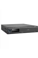


| Product Type | Digital Voice Recorder |
| Brand | Samsung |
| Model | SRN-645 |
| Dimensions (Approx.) | 115 x 42 x 18 mm |
| Weight (Approx.) | 75 g (with batteries) |
| Power Source | 2 x AAA batteries (recommended: rechargeable) |
| Battery Life (Approx.) | Up to 20 hours (LP mode) |
| Internal Storage | 8 GB flash memory |
| Expandable Storage | microSD card slot (up to 32 GB) |
| Recording Format | MP3, WAV (adjustable bitrate) |
| Recording Modes | LP (Low Quality), SP (Standard), HQ (High Quality) |
| Noise Reduction | Built-in noise reduction filter |
| Microphone | Built-in stereo microphone |
| Playback | Built-in speaker, earphone jack (3.5 mm) |
| Connection | USB 2.0 for file transfer |
| Voice Activation | VAS (Voice Activated System) for automatic start/stop |
| Timer Recording | Yes, schedule recording |
| Display | LCD with backlight (date, time, file info) |
| Languages Supported | Multiple (English, French, Spanish, etc.) |
| Maintenance | Clean exterior with soft dry cloth. Keep away from moisture. |
| Safety | Do not disassemble. Avoid dropping. Use only specified batteries. |
| Spare Parts | Batteries, earphones, USB cable (standard micro-USB) |
| Repairability | Battery compartment user-accessible. For internal repairs, contact authorized service. |
| Warranty | 1 year limited warranty (check local regulations) |
Frequently Asked Questions - SRN-645 SAMSUNG
User questions about SRN-645 SAMSUNG
0 question about this device. Answer the ones you know or ask your own.
Ask a new question about this device
Download the instructions for your Voice recorder in PDF format for free! Find your manual SRN-645 - SAMSUNG and take your electronic device back in hand. On this page are published all the documents necessary for the use of your device. SRN-645 by SAMSUNG.
USER MANUAL SRN-645 SAMSUNG
©2011 Samsung Techwin Co., Ltd. All rights reserved.
Trademark

SAMSUNG TECHWIN is the registered logo of Samsung Techwin Co., Ltd.
The name of this product is the registered trademark of Samsung Techwin Co., Ltd.
Other trademarks mentioned in this manual are the registered trademark of their respective company.
Restriction
Samsung Techwin Co., Ltd shall reserve the copyright of this document. Under no circumstances, this document shall be reproduced, distributed or changed, partially or wholly, without formal authorization of Samsung Techwin.
Disclaimer
Samsung Techwin makes the best to verify the integrity and correctness of the contents in this document, but no formal guarantee shall be provided. Use of this document and the subsequent results shall be entirely on the user's own responsibility. Samsung Techwin reserves the right to change the contents of this document without prior notice.
Warranty
If the product does not operate properly in normal conditions, please let us know. Samsung Techwin will resolve the problem for free of charge. The warranty period is 3 years. However, the followings are excluded:
• Data loss due to a damaged hard disk - If the system behaves abnormally because you run a program irrelevant to the system operation. • Data loss due to virus infection • Deteriorated performance or natural worn-out in process of time - Sensory phenomenon that does not affect the performance or quality of the product (ex: working noise).
◆Design and specifications are subject to change without prior notice.
The default password can be exposed to a hacking thread so it is recommended to change the password after installing the product.
Note that the security and other related issues caused by the unchanged password shall be responsible for the user.
Preface
Thank you for choosing a Samsung Network Video Recorder (Disk Player) product.
This instruction manual provides detailed information and instructions for the NVR network DVR products. Please read this manual and any supplementary document(s) thoroughly before attempting to install and/or operate the product.
The contents of this manual, and the software and hardware explained herein, are protected by copyright law. All copy, reprint and translation to other languages of a part of or all of the contents of this instruction manual without permission of Samsung Techwin Co., Ltd. are expressly prohibited except for fair use within the scope of copyright law.
The specifications of the product may change without prior notice for product improvement.
Product Warranty and Limited Liability
The manufacturer of this product is not responsible for the sale of the product, nor does the manufacturer delegate such responsibility to a third party. The product warranty does not extend to any accident, neglect, alteration, or misuse of the product. Furthermore, this warranty does not cover any components or parts that are not supplied by the manufacturer of this product.
The product warranty period is for three years from the purchase date. However, the warranty does not cover any of the following problems, and a nominal service fee will be charged if:
● Product has been improperly used or handled by user. ● Product has been disassembled and/or altered by user. ● Product has been damaged by connecting a power supply with improper specifications. - Product has been damaged due to an "Act of God" (fire, flood, tsunami, natural disaster, etc.) ● To replace expendable components: HDD, Fan, etc. (The warranty for the HDD and Fan is valid for one year from the purchase date.)
This warranty covers only the product supplied with the warranty.
After the warranty period (three years) has expired, a service fee will be charged for any inspection and/or repair for the product. During the warranty period, a service fee will be charged for repair and/or inspection for the product for any problems that are not covered by the warranty.
This product is not an anti-theft or fire-prevention device; the manufacturer is not responsible for any damage to property or personnel that may occur during its use.
This product must be installed by skilled and experienced personnel; self-installation by the user is prohibited. Self-installation by the user may result in fire, electrocution, and/or product malfunctions. Please contact your local dealer for assistance with the installation of the product.
The contents of this manual may change in order to accommodate upgrades in firmware and/or software. Also, the specifications and/or design of this product may change without prior notice for product improvement.
Table of Contents
Preface....1
Product Warranty and Limited Liability ...... 1
Table of Contents....3
Chapter 1. Overview ...... 6
1.1. Safety Precautions ...... 6 1.2. Product Contents....9
Chapter 2. Part Names ...... 10
2.1. Front Panel.... 10
2.2. Back Panel....12
2.3. Default Settings ...... 13
2.3.1. Monitoring Page.... 13 2.3.2. Playback Page 13 2.3.3.Config Page 14 2.3.4. System Page....17
Chapter 3. Installation ...... 18
3.1. Installing and Connecting Product ...... 18
3.1.1. Supplying Power and Operating the Product 18 3.1.2. Configuring the Network .... 18 3.1.3. Internal HDD 19 3.1.4. External HDD 22 3.1.5. Sensor....23 3.1.6. Relays 24 3.1.7. USB 25
3.2. Connecting to the Website....26
3.2.1. Connecting Cable 26 3.2.2. Adding an IP Address.... 26 3.2.3. Connecting and Changing Settings 28
Chapter 4. Operation ...... 31
4.1. System Requirements....31 4.2. Compatible Web Browsers 31 4.3. Login 32 4.4. Monitoring 33
4.4.1. Splitting Screen and Changing Channels 33 4.4.2. Video Control 34 4.4.3. PTZ Control.... 34 4.4.4. OSD Control....35
4.5. Playback 37
4.5.1. Time Search....37 4.5.2. Event Search 39
4.6.Config 42
4.6.1. Status 43 4.6.2. Record Setup 44 4.6.3. Event Setup 45 4.6.4. Camera Setup....49 4.6.5.HDD Setup 53 4.6.6. Network Setup ....59 4.6.7.Time Setup 64
4.7. System 66
4.7.1. Upgrade 67 4.7.2. System Log 69 4.7.3.User Setup 72 4.7.4.Backup 73
Chapter 5. LCD Setup....77
5.1. System 78
5.1.1. Checking Firmware Version....78 5.1.2. Turning On/Off Beep 78 5.1.3. Relay Off 79 5.1.4. System Update 79 5.1.5. Initializing Settings 80 5.1.6.HDD Check 81 5.1.7.Shutting the System Down 82
5.2. Network Setup....83
5.2.1. Monitor Ethernet Port Setup 83 5.2.2. Source Ethernet Port Setup 86 5.2.3. Storage Ethernet Port Setup 87
5.3.HDD Mode Setup 88
5.4. Removing HDDs....91
5.5. Formatting HDDs 92
5.5.1. Formatting a Single Internal HDD 92 5.5.2. Formatting All Internal HDDs 93 5.5.3. Formatting a Single External HDD....93 5.5.4. Formatting All External HDDs 95 5.5.5. Formatting All HDDs 96
Troubleshooting....97
Product Specifications....99
Product Dimensions....101
Chapter 1. Overview
This digital video recorder plus disk player features HDD storage and playback capabilities for 64/32-channel digital video.
Setting up this recorder is easy; you may use the buttons on the front of the product, or connect to the product remotely via a network.
With proven performance and reliability, the NVR is a self-sufficient video recorder as well as ideal for digital video feed storage for monitoring systems of banks, apartment buildings, and public offices that require a high security level. Since video is stored on hard disk, there is no loss in picture quality due to repeated playback from the storage media. Further, since all video data is stored as digital files, it is easily and quickly searchable.
This high-resolution video recorder features a large storage capacity and also comes with a wide variety of user-friendly features such as: Simultaneous recording and playback capabilities, motion detection, PTZ (pan, tilt, zoom) control, password, real-time voice data recording, convenient access permissions setup using Key Lock, and maintenance of up to 10,000 event lists and log files.
1.1. Safety Precautions
Warning
The following information or instruction is vital for user safety; please read it thoroughly to avoid serious injury or death.
◆ Installing the Product
Please check the power outlet voltage (AC 100V~240V) before you connect the power to the outlet. Make sure that the product is switched off before you install it. To avoid the risk of electric shock and/or fire, do not install the product in a damp area. The product must be grounded to reduce the risk of electric shock.
Using the Product
Opening or removing the product case will expose you to the risk of electric shock; do not open or remove the case unless you are a qualified technician.
To prevent electrical fire, do not connect multiple power cords to a single outlet. Do not place heavy objects or vessels containing water on the unit since it can cause serious malfunctions. Do not use this item in a location containing propane gas, gasoline, or other flammable substances to avoid risk of explosion or fire. To avoid the risk of electric shock, do not touch the power plug with moisture on your hands. Make sure that no electrically conductive material enters the cooling vent. Do not pull on the power plug with any force; a damaged plug may cause electric shock or fire.
Disassembling and Cleaning the Product
There is a risk of malfunction, shock, or other dangers. Do not disassemble or attempt to fix or alter the product yourself. Do not clean the product with water, paint thinner, or other organic solvent as doing so may cause product malfunctions and/or electric shock. When cleaning the product, use a dry cloth to wipe the exterior of the device.
Caution
Misuse or wrongful operation of the item may result in injury or damage to the item. It indicates caution should be observed when operating.
Installing the Product
When installing the product, please leave at least 15 cm of space between the cooling vent and the wall for proper heat dissipation. To prevent user injury and product damage, please install the product on a level surface with no risk of the product falling. Avoid installation in an environment where the product will be exposed to heat or direct sunlight; product deformation and/or damage may result.
When installing the closure, take into consideration the operating temperature and humidity of the installation environment according to the product specifications (see Appendix).
Using the Product
Avoid shock and vibration while operating or moving the item. Do not move the product while it is in operation; do not expose the product to strong impact or throw the product. If you wish to add a hard disk to the product, please contact your vendor; adding a non-recommended hard disk may cause the product to function abnormally. Arbitrarily adding a hard disk to the product will void your product warranty. This product is not an anti-theft or fire-prevention device; the manufacturer is not responsible for any damage to property or personnel that may occur.
Caution
Samsung Techwin recommends the installation of a UPS (Uninterrupted Power Supply) with all its recording products.

Samsung Techwin cares for the environment at all product manufacturing stages to preserve the environment, and is taking a number of steps to provide customers with more environmentally friendly products.
The Eco mark represents Samsung Techwin's will to create environmentally friendly products, and indicates that the product satisfies the EU RoHS Directive.
1.2. Product Contents
The contents of this product are as shown below.
 Power Cord Power Cord |  Key Key |  Rack Mount and Fixture Screws Rack Mount and Fixture Screws |
 HDD Fixture Screws HDD Fixture Screws |  User's Manual User's Manual |  Quick Reference Guide Quick Reference Guide |
 NET-I Viewer/User's Manual CD NET-I Viewer/User's Manual CD |  Cross Cable Cross Cable |  HDD Tray (4EA) HDD Tray (4EA) |
Chapter 2. Part Names
2.1. Front Panel

| No. | Name Function | |
| 1 | Key Lock Turning the | key completely engages the lock, so the buttons on the front panel cannot be accessed and the HDD bay door cannot be opened. |
| 2 | SATA-Bracket Mounts | hard disks for storing recorded video. Up to four hard disks can be mounted. Mounted HDDs are referred to as Internal HDD1 (upper left), Internal HDD2 (upper right), Internal HDD3 (lower left), and Internal HDD4 (lower right.) |
| 3 | Internal HDD1 A | blue indicator means that Internal HDD1 is installed and functioning normally. A red indicator means that Internal HDD1 is not functioning properly. |
| 4 | Internal HDD2 A | blue indicator means that Internal HDD2 is installed and functioning normally. A red indicator means that Internal HDD2 is not functioning properly. |
| 5 | Internal HDD3 A | blue indicator means that Internal HDD3 is installed and functioning normally. A red indicator means that Internal HDD3 is not functioning properly. |
| 6 | Internal HDD4 A | blue indicator means that Internal HDD4 is installed and functioning normally. A red indicator means that Internal HDD4 is not functioning properly. |
| 7 | EXTERNAL HDD1 | A blue indicator means that an external HDD is connected to the rear eSATA Port1 and functioning normally. A red indicator means that External HDD1 is not functioning properly. |
| 8 | EXTERNAL HDD2 | A blue indicator means that an external HDD is connected to the rear eSATA Port2 and functioning normally. A red indicator means that External HDD2 is not functioning properly. |
| 9 | EXTERNAL HDD3 | A blue indicator means that an external HDD is connected to the rear eSATA Port3 and functioning normally. A red indicator means that External HDD3 is not functioning properly. |
| 10 | EXTERNAL HDD4 | A blue indicator means that an external HDD is connected to the rear eSATA Port4 and functioning normally. A red indicator means that External HDD4 is not functioning properly. |
| 11 | REC A red indicator means that the product is in recording mode. | |
| 12 | ALARM A blue indicator means that an event in Input Group has occurred. | |
| 13 | ERROR A red indicator means that the product is not functioning properly. | |
| 14 | RAID A blue indicator means that the product is running in RAID mode. | |
| 15 | LINK/ACT1 A blinking blue indicator means that a network cable is properly connected to the Monitor Ethernet Port, and data communication is taking place properly. | |
| 16 | LINK/ACT2 A blinking blue indicator means that a network cable is properly connected to the Source Ethernet Port, and data communication is taking place properly. | |
| 17 | LINK/ACT3 A blinking blue indicator means that a network cable is properly connected to the Storage Ethernet Port, and data communication is taking place properly. | |
| 18 | POWER A red indicator means that the product is powered on. | |
| 19 | Config Ethernet Port | Used to connect the product to a computer for the system configuration. |
| 20 | LCD Panel | The panel displays the current status of the product; it can also be used to change the system configuration with the adjacent buttons. |
| 21 | ESC Button This button is used to change the system configuration. 'Chapter 5 LCD Setup' covers its use in detail. | |
| 22 | Direction Button Enter Button | This button is used to change the system configuration. 'Chapter 5 LCD Setup' covers its use in detail. |
2.2. Back Panel

| No. | Name Function | |
| 1 | AC IN Used to connect the product power cable. | |
| 2 | SMPS FAN This fan cools the power supply. | |
| 3 | DC FAN This fan cools the inside of the product. | |
| 4 | Monitor Ethernet Port A network port that allows the product to connect to a PC to run Web Viewer. | |
| 5 | USB Port Used to upgrade the firmware version of the product. | |
| 6 | Power Button Turns on or off the product. | |
| 7 | Source Ethernet Port A network port that connects the product to the video camera. | |
| 8 | SENSOR IN / RELAY OUT | Used to connect a sensor or alarm. |
| 9 | GROUND | A terminal that is used to ground the frame to an external device. |
| 10 | Storage Ethernet Port | Used to connect NAS (Network Attached Storage) within the same network. |
| 11 | eSATA Port1 | Used to connect an external HDD. |
| 12 | eSATA Port2 | Used to connect an external HDD. |
| 13 | eSATA Port3 | Used to connect an external HDD. |
| 14 | eSATA Port4 | Used to connect an external HDD. |
| 15 | RS232C Port | Unused terminal. |
2.3. Default Settings
The following are the factory default settings for the product.
2.3.1. Monitoring Page
| Main Menu Sub Menu Default Setting | ||
| Auto Sequence Off | ||
| Display Mode 16Ch display | ||
| Group | 1 | |
| Channel | 1 | |
| Info | On | |
| DIT | Off | |
| PT, ZF PT Activated | ||
| OSD | Off | |
| PTZ speed 3 | ||
2.3.2. Playback Page
| Main Menu Sub Menu Default Setting | ||
| Time | Channel | - |
| Calendar | - | |
| Time | - | |
| Event | Event Type | - |
| Channel | - | |
| Date / Time | - | |
2.3.3. Config Page
Record Setup
| Main Menu Sub Menu Default Setting | ||
| Normal Record Config All frames | ||
| Event Record Config | Input GroupActiveInactivePre Recording TimePost Recording Time | own eventAll framesI frames5 Sec5 Sec |
| Record | ButtonTime Table | Normal Record selectedAlways Normal Record |
Event Setup
| Main Menu Sub Menu Default Setting | ||
| Local Sensor Type | Sensor1 | Normal Open |
| Sensor2 | Normal Open | |
| Event Group | Input Group | - |
| Output Group | - | |
| Action Group | - | |
◆ Camera Setup
| Main Menu Sub Menu Default Setting | ||
| Channel List | Open Channel ListSelect Channel | Ch1 ~ Ch16Ch01 |
| Channel Setup | Disable/EnableChannel NameModelConnection TypeIPConnection PortIDPasswordPicture TypeATC ModeVideo QualityVideo ResolutionVideo Framerate | DisableCh01, Ch02, Ch03, ...-Static IP0.0.0.04000--MPEGOffHighD110 |
HDD Setup
| Main Menu Sub Menu Default Setting | ||
| HDD | Repeat | Recording On |
| AutoDeletion | Mode | Off |
| Duration | 180 | |
| RAID Mode Normal | ||
| NAS Configuration | Nas Port | Nas1 |
| Use | Disable | |
| Name | - | |
| Default Folder | - | |
| IP | 0.0.0.0 | |
| ID | - | |
| Password | - | |
Network Setup
| Main Menu Sub Menu Default Setting | ||
| Monitor Ethernet Port | Connection TypeIP AddressSubnet MaskGatewayConnection PortHttp PortATC Mode | Static IP0.0.0.00.0.0.00.0.0.0400080Disable |
| DDNS | UseServer DomainIDPassword | Disablewww.samsungipolis.com-- |
| Source Ethernet Port | Connection TypeIP AddressSubnet MaskGateway | Static IP0.0.0.00.0.0.00.0.0.0 |
| Source DHCP Server | UseIP Range | Disable0.0.0.0 ~ 0.0.0.0 |
| Storage Ethernet Port | Connection TypeIP AddressSubnet MaskGateway | Static IP0.0.0.00.0.0.00.0.0.0 |
| DNS | DNS1DNS2 | 168.126.63.1168.126.63.2 |
| RTP/RTSP | Use RTSPRTSP PortRTP PortUse MulticastMulticast Address | Disable5544000Disable224.0.1.1 |
| SMTP Server NameUse AuthenticationIDPasswordE-Mail To | -Yes-- | |
Time Setup
| Main Menu Sub Menu Default Setting | ||
| Time Configuration | Date Format | mm.dd.yy |
| Time Format | 24h | |
| Time Zone | (GMT 00:00) Greenwich Mean Time | |
| Use DST | Disable | |
| NTP | Use Client | Disable |
| Use Server | Disable | |
| Public Server1 Address | pool.ntp.org | |
| Public Server2 Address | asia.pool.ntp.org | |
| Public Server3 Address | europe.pool.ntp.org | |
| Public Server4 Address | north-america.pool.ntp.org | |
| Public Server5 Address | time.nist.gov | |
2.3.4. System Page
User
| Main Menu Sub Menu Default Setting | ||
| Admin | Password | 11111111 |
| User | ID | user |
| Password | 22222222 | |
| Authority | Only Monitoring is Allowed. | |
Chapter 3. Installation
3.1. Installing and Connecting Product
3.1.1. Supplying Power and Operating the Product
Connect the power cord to the product as shown in the picture below.

- Once the power cord is securely connected, press the power switch on the rear panel to boot the system.
- When the product is turned on, you can press the power switch briefly to turn off the product.
- When the system has encountered an error and you can't turn it off normally, you can press and hold down the power switch for five seconds to force the system to shut down.

3.1.2. Configuring the Network
The following picture is an example of a network diagram using the NVR. The 3 network ports on the product back panel are for a computer, camera, and NAS (Network Attached Storage). Please refer to "2.2. Back Panel".
The rear panel network ports can be used for devices within the same network, or in different networks as shown in the example diagram.
![graph TD PC["PC"] --> LAN["LAN"] IP_Camera["IP Camera"] --> LAN NAS["NAS"] --> Direct_Connection["Direct Connection"] LAN --> External["External Device"] LAN --> Internal["Internal Component"] IP_Camera --> Internal NAS --> Internal External --> Internal Internal --> External style PC fill:#f9f,stro…](/content/2026/05/995117/images/029ab11309d383607aa18fe43c20d62515cf837f156bb0662a0d4a8e020ad3b5.jpg)
3.1.3. Internal HDD
Open the HDD Bay as shown below to add, remove, or replace an internal HDD.
① Press PUSH: to open the Locking Door. ② Turn Key Lock counterclockwise to unlock.

③ Open the HDD Door.

④ While pressing the HDD Hook down, pull on the handle to pull out the SATA Bracket.

⑤ Unscrew the fixture screws on the SATA Bracket before removing the HDD; fasten the screws securely after you insert the HDD in the SATA Bracket.

⑥ Make sure that the SATA Bracket is pushed back all the way in the HDD Bay, and close the HDD Door.

⑦ Turn Key Lock clockwise to lock.

⑧ Close the Locking Door.

⑨ When adding a new, unformatted HDD, the product automatically formats the HDD.
Formatting HDD
is in Progress...
displaying the formatting process in the front LCD.
Internal HDD [2]
Added successfully!
Upon completing the formatting process, the message above is displayed in the LCD along with a blue indicator in the HDD LED, indicating that the new HDD is ready to use.

Do Not remove an HDD while the product is in operation. To safely remove HDDs, please refer to "5.4. Removing HDDs".

To lock the HDD door, please make sure to turn Key Lock clockwise completely.
3.1.4. External HDD
The NVR supports an eSATA interface for connecting external storage devices; four eSATA ports are located on the rear panel. The product can have up to 20 TB of storage capacity by utilizing the internal HDDs and eSATA ports. (Based on 1TB data capacity per HDD.)
An external eSATA HDD can be connected to the eSATA port on the rear panel as shown on the next page. Note that an eSATA port does not supply power to the device connected to it; the external device must supply its own power.

Note
- You may connect an external HDD while the product is in operation. However, this may result in certain models of external HDDs not being detected. As such, it is recommended that you connect any external HDD by following the steps outlined below.
- Turn the product off.
- Connect the external HDD (also turned off) to the product with an eSATA interface cable.
- Turn on the external HDD.
- Turn on the product.
- The eSATA cable is not included with the product.
The following are specifications and operating conditions for sensor input.
| Spec | Number of Input Circuits 2 | |
| Input Types N.C, N.O | ||
| Supported Sensor Types Dry Contact sensors. | ||
| Connection Type Attach stripped wire connections to the terminal block. | ||
| Power | DC | 150V |
| Output Current Typical DC 1 | 2mA | |
Please refer to the diagram on the next page to connect sensor inputs. It illustrates an example of a dry contact sensor being connected to the product.

For detailed instructions on connecting sensors, please refer to "4.6.3. Event Setup"
3.1.6. Relays
The following are specifications and operating conditions for alarm output.
| Spec. | Number of Input Circuits 2 Relays | |
| Output Types Dry Contact. | ||
| Connection Type Attach stripped wire connections to the terminal block. | ||
| Power | DC | 30V 1A |
| AC | 125V 0.5A | |
When connecting the relay outputs, first determine the attributes of the device to be connected (Normal Open, or Normal Close), then connect the device by referring to the diagram below.

| RELAY OUT 1 NC CM NO | |||
| Normal Close O | O | - | |
| Common | - | O | - |
| Normal Open - | O | O | |
| RELAY OUT 2 NC CM NO | ||
| Normal Close O | O | - |
| Common | - | O |
| Normal Open - | O | O |
For detailed instructions on connecting the relay output, please refer to "4.6.3. Event Setup"
3.1.7. USB
The USB ports on the rear panel are used to upgrade the product's firmware with the buttons on the front panel. Please refer to "5.1.4. System Update"
3.2. Connecting to the Website
3.2.1. Connecting Cable
Press PUSH: on the front panel to open the Locking Door, then connect a PC to the Front Panel Network Port with the supplied crossover cable as shown in the illustration below. (When using a hub to connect the product to a computer, you may use a normal LAN cable instead of a cross-over cable.)

3.2.2. Adding an IP Address
In your computer, click Start > Control Panel > Network Connections > Local Area Connection > Properties.

Select Internet Protocol (TCP/IP.) Click the Properties button then in the Internet Protocol (TCP/IP) Settings dialog, click the Advanced button to open the Advanced TCP/IP Settings
dialog. (If the "Obtain an IP address automatically" option is checked under the Internet Protocol (TCP/IP) Properties window, please click the "Use the following IP address" radio button option before proceeding.)
![Advanced TCP/IP Settings IP Settings DNS WINS Options IP addresses IP address Subnet mask 123.123.123.123 255.255.255.0 [192.T68.T.251] 255.255.255.0 Add... Edit... Remove Default gateways: Gateway Metric 123.123.123.0 Automatic Add... Edit... Remove ✓ Automatic metric Interface metric: OK Cancel](/content/2026/05/995117/images/85737aee99718d7994128ac7c889fd3ea310641d0141889fe4e0f941b1bb36ba.jpg)
Click Add under IP addresses then enter 192.168.1.xxx. The NVR uses 192.168.1.100 as the IP address; you cannot use the address for your computer's internal IP address.
3.2.3. Connecting and Changing Settings
Type 192.168.1.100 in your Internet browser address bar then press Enter.

In the login window, enter admin as the User ID and 11111111 for the Password. Click Login to connect to the product.

When connecting to the product for the first time, no video displays as no network or camera is set up.
Clicking Config at the top of the screen directs you to a new page, as shown in the screenshot below.

Clicking System directs you to a new page, as shown in the screenshot below.

Use the left menu to set up the product. For detailed instructions on each menu item, please refer to "4.6. Config" and "4.7. System". Once a network is set up,
You can use the Monitor Ethernet Port on the product back panel to connect to the product.
Note
- The IP address for the front port is fixed as 192.168.1.100; this value cannot be changed.
- It is strongly recommended that you change the default administrator password (Admin PW) as soon as possible. For instructions on changing the password, please refer to "4.7.3. User Setup".
Chapter 4. Operation
4.1. System Requirements
| Category Minimum Recommended | ||
| CPU Intel Core 2 Quad2.5GHz or higher | Intel i7 or higher | |
| Main Memory 3GB | 4GB or higher | |
| Video Memory 512 | MB 1GB or higher | |
| Display Resolution 1,280 x 1,024 | ||
| Hard Disk 1GB or higher | ||
| Operating System | Windows XP Professional / Windows Vista Business / Windows 7 | |
| Network Gigabit | Ethernet | |
| Miscellaneous DirectX 9.0 or higher | ||
4.2. Compatible Web Browsers
Web Viewer is optimized for use with Microsoft Internet Explorer 6.0 or higher. You must have Microsoft Internet Explorer 6.0 or higher installed on your PC to ensure trouble-free operation of Web Viewer.
4.3. Login
Open a web browser, and then enter the IP address of the product. You are directed to the login page. Enter your ID and password, then click the Login button to connect to the system. You are directed to the Monitoring Page. If you have not set up your own ID and password yet, the default ID is "admin", and the default password is "11111111" (without the quotation marks). For instructions on changing the ID and password, please refer to "4.7.3. User Setup".


Note
- To connect to the product using the front network port, please make sure to enter 192.168.1.100. To connect to the product using the rear Monitor Ethernet Port, make sure to enter the IP address assigned to the port.
- The connecting port and computer must be within the same network.
- For an HTTP port number with any value other than 80, then the access address is http:// : . For example if the IP address is 192.168.1.110, and the HTTP port number is 8080, then the address for Web Viewer is http://192.168.1.110:8080.
- For instructions on changing the Monitor Ethernet Port IP address, please refer to "4.6.6. Network Setup"
4.4. Monitoring
If you are logging in to your Network Video Recorder for the first time, or if you click the Monitoring button at the top of Web Viewer, you will be directed to the Monitoring Page where you can view the video feeds from the cameras connected to your product.
![iPOLiS Network Security Solution - Monitoring, Playback, Config, System, admin, Logout, Help. Auto sequence, Group 1, Channel 1, Pause, Capture, Info, DIT, PT, ZF, OSD, Set, Esc. PTZ speed: 1 2 3 4 5 6, Slow, Fast. Logs: [2008/04/15 01:47:07] MD (CN(ch40)), [2008/04/15 01:03:57] MD (DIF(chRT)), [200…](/content/2026/05/995117/images/64c27f43b8a048a9f784cfc2572aeaa53ffe830c207cdadc46b7b15d7043c41a.jpg)


- TRADEMARK
- RESTRICTION
- DISCLAIMER
- WARRANTY
- PREFACE
- PRODUCT WARRANTY AND LIMITED LIABILITY
- TABLE OF CONTENTS
- CHAPTER 1. OVERVIEW
- CHAPTER 2. PART NAMES
- CHAPTER 3. INSTALLATION
- CHAPTER 4. OPERATION
- CHAPTER 5. LCD SETUP
- NETWORK SETUP
- HDD MODE SETUP
- REMOVING HDDS
- FORMATTING HDDS
- TROUBLESHOOTING
- PRODUCT SPECIFICATIONS
- PRODUCT DIMENSIONS
- SAFETY PRECAUTIONS
- ◆ INSTALLING THE PRODUCT
- USING THE PRODUCT
- DISASSEMBLING AND CLEANING THE PRODUCT
- MISUSE OR WRONGFUL OPERATION OF THE ITEM MAY RESULT IN INJURY OR DAMAGE TO THE ITEM. IT INDICATES CAUTION SHOULD BE OBSERVED WHEN OPERATING
- INSTALLING THE PRODUCT
- SAMSUNG TECHWIN RECOMMENDS THE INSTALLATION OF A UPS (UNINTERRUPTED POWER SUPPLY) WITH ALL ITS RECORDING PRODUCTS
- PRODUCT CONTENTS
- FRONT PANEL
- BACK PANEL
- DEFAULT SETTINGS
- MONITORING PAGE
- PLAYBACK PAGE
- CONFIG PAGE
- SYSTEM PAGE
- INSTALLING AND CONNECTING PRODUCT
- SUPPLYING POWER AND OPERATING THE PRODUCT
- CONFIGURING THE NETWORK
- INTERNAL HDD
- EXTERNAL HDD
- RELAYS
- USB
- CONNECTING TO THE WEBSITE
- CONNECTING CABLE
- ADDING AN IP ADDRESS
- CONNECTING AND CHANGING SETTINGS
- SYSTEM REQUIREMENTS
- COMPATIBLE WEB BROWSERS
- LOGIN
- NOTE
- MONITORING
Brand : SAMSUNG
Model : SRN-645
Category : Voice recorder