
KH900CCS - Cooker KELVINATOR - Free user manual and instructions
Find the device manual for free KH900CCS KELVINATOR in PDF.


| Product Type | Built-in Electric Ceramic Hob |
| Brand | Kelvinator |
| Model | KH900CCS |
| Number of Cooking Zones | 4 (including one extendible zone) |
| Cooktop Material | Glass-ceramic |
| Control Type | Rotary knobs with energy regulator |
| Residual Heat Indicators | Yes, one per zone (lights until zone cools below 50°C) |
| Minute Minder | Yes, 0–60 minutes with audible ring |
| Extendible Zone Activation | Turn knob beyond position 8 until click, then set 1–8 |
| Power Supply Options | 220–240 V~ / 380–415 V (see wiring diagrams) |
| Installation Class | Y (must be installed by qualified electrician) |
| Dimensions (Width x Depth x Height) | Approximately 590 mm x 520 mm x 50 mm |
| Weight | Approximately 10 kg |
| Cutout Size (Work Surface) | Refer to Fig. 1 and 2 in manual; allow 50 mm rear clearance, 110 mm left clearance |
| Max. Surrounding Temperature | 100°C (for adjacent units) |
| Cleaning Instructions | Use recommended ceramic hob cleaner; avoid abrasive materials |
| Safety Features | Residual heat indicators, child safety warnings, automatic shutdown if surface damaged (disconnect immediately) |
| Warranty | As per manufacturer's policy (check documentation) |
| Recommended Pans | Flat-bottomed, dry, clean pots with base diameter slightly larger than zone |
| Included in Box | Hob, seal, fixing brackets, installation manual |
Frequently Asked Questions - KH900CCS KELVINATOR
User questions about KH900CCS KELVINATOR
0 question about this device. Answer the ones you know or ask your own.
Ask a new question about this device
Download the instructions for your Cooker in PDF format for free! Find your manual KH900CCS - KELVINATOR and take your electronic device back in hand. On this page are published all the documents necessary for the use of your device. KH900CCS by KELVINATOR.
USER MANUAL KH900CCS KELVINATOR
Thank you for choosing our product.
We are sure that this complete, modern, functional and practical electrical appliance will fully meet your requirements as it has been carefully designed and manufactured with high-quality materials.
We recommend that you read and follow these instructions carefully. They will enable you to use this electrical appliance to its full potential the very first time you use it.
THE DOCUMENTATION FOR THIS APPLIANCE MUST BE KEPT IN A SAFE PLACE FOR FUTURE CONSULTATION.
We hope you enjoy using this modern hob. Best wishes
THE MANUFACTURER
CONTENTS
User's instructions
Installation 4
U s e
Maintenance 6
Fitter's instructions
Installation 7
P o s i t i o n
Electrical connections
IMPORTANT:
THIS APPLIANCE IS DESIGNED FOR DOMESTIC USE. THE MANUFACTURER IS NOT LIABLE IN THE EVENT OF DAMAGE TO PERSONS OR OBJECTS CAUSED BY INCORRECT INSTALLATION, IMPROPER OR ERRONEOUS USE.
USER'S INSTRUCTIONS
INSTALLATION
All the installation procedures (electrical connections) must be carried out by an electrician in accordance with the standards and laws in force. This product is in installation class Y.
The equipment may be installed in any type of unit made of brickwork, metal, wood, veneered and laminated plastic, as long as they are able to withstand a maximum temperature of 100^ C.
Keep a distance of 50 mm from the back edge and 110 mm from the left side.
See figure 1.
For specific instructions, see the fitter's section.
Connect extremities of return rods in the relative axles placed in the oven and in the control panel. Then fix oven in relative site using fitting screws (for control panel use special little claps).
USE
CONTROL KNOBS and COOKING ZONE (Fig. 4)
Cooking zones are controlled by knobs connected to an energy regulator. Clockwise numbers 1 to 8 are used to indicate cooking settings where 1 is the minimum setting and 8 the maximum setting. Number 0 is the off position. Extendible zones, on models where available, are activated on position 8.
To switch on the extended zone, turn the knob beyond the 8 setting until a click is heard, then return it to any setting from 1 to 8.
The zone controlled by each knobs is identified by the adjacent cooking zone identification.
RESIDUAL HEAT INDICATOR (HOT SURFACE INDICATOR)
Each heating elements has a corresponding residual heat indicator light. This switches on automatically once the corresponding cooking zone is switched on. Once a cooking zone has been turned off, the corresponding light will stay on for a period of time necessary for the zone to cool down to 50°C.
During this time avoid touching the cooking zone and take precautions to ensure children cannot touch it.
MINUTE MINDER 0-60 min
The minute minder may be used for timing the cooking period. It does not switch off the plates but gives a loud ring when the selected time has elapsed. Turn the control knob to 60 minutes to wind up the mechanism then return the knob to the desired time period.
When the time has elapsed the timer will ring for a few seconds.
CONTROL PANEL

SAFETY TIPS FOR USING THE COOKTOP
Before switching on, check which knob controls the desired cooking zone. It is best to place the pot or pan on the cooking zone before switching on, and remove it only after switching off.
Use only flat-bottomed pans with a regular surface (exercise caution with cast iron pans). Irregular bottoms can scratch the glass-ceramic surface. Check the bottom is clean and dry
Do not use the cook top if the surface is broken or damaged.
Bear in mind that the cooking zones remain hot for a relatively long time (about 30 min.) after switching off.
Do not allow heavy or sharp objects to fall on the glass-ceramic cook top.
If you find a crack on the cook top, disconnect the appliance from the mains electricity immediately and contact the After-sales Service.
Do not stare at the halogen lamps on the cook top.
Never cook food directly on the glass-ceramic cook top; always use suitable pots or containers.
Always keep children away from the appliance when it is in use.
Do not leave hot fat or oil unattended. If overheating occurs, these could catch fire.
Use only pots with a solid level base. An uneven base can prolong cooking times and waste energy.
Use pots with a base diameter slightly larger than the plate. This ensures even heat distribution and prevents spillage from dripping onto and staining the hot plate.
Thermal shock could damage the plates. Do not put cold pots on very hot plates.
| Knob Setting | Cooking operation |
| 0 | Off |
| 12 | For melting processes (butter or chocolate) |
| 23 | For keeping foods hot and heating small amounts of liquids |
| 45 | For heating larger amounts and beating custards and sauces |
| 67 | Slow boiling, for soups, pasta and risotto, continuing steaming processes, and cooking steaks and fried foods in general |
| 7 | Browning meat, roasted potatoes, fried fish, bringing large amounts of water to the boil |
| 8 | Quick frying, char-grilled steaks, ect. |
MAINTENANCE
ANY ADJUSTMENT, MAINTENANCE, ETC. MUST BE CARRIED OUT WITH THE HOB UNPLUGGED AT THE MAINS.
INSTRUCTION FOR USE
Before cooking for the first time, it is necessary to clean the surface of the appliance. This should be done using only recommended ceramic hob cleaners.
After cleaning, the appliance should be operated in the following manner to remove any residues or moisture that may be present within the appliance: one at a time, turn the heating plates on and set at maximum and operate (without pans) for a period of 5 minutes, then turn off. An odour may be given off during this operation, this is normal.
FITTER'S INSTRUCTION
INSTALLATION
All the installation procedures (electrical connections) must be carried out by an electrician in accordance with the standards and laws in force.
ANY ADJUSTMENT, MAINTENANCE, ETC. MUST BE CARRIED OUT WITH THE HOB UNPLUGGED AT THE MAINS.
POSITION
The hob is designed to be fitted into a work surface, which is larger, then the hob. See Fig. 1 and 2.
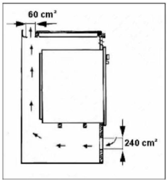
If the hob is to be fitted into a surface/oven, follow the instructions of the oven manufacturer and ensure that the ventilation complies with Fig. 6. . The hob is supplied with a seal to prevent infiltration into the unit. The seal must be fitted carefully into its seat. Fasten the hob with the brackets, as shown in Fig. 5.
ELECTRICAL CONNECTIONS
Before connecting the electrics, ensure that:
- the household power supply meets the requirements on the plate located under the hob and featured in this booklet;
- there is an earth system and that it works correctly;
- for a direct connection to the mains, there must be an omni polar cut-off device on the power-supply line, with a contact cut-off distance of 3 mm or over. The device must also be located in an accessible position near the hob (the yellow-green earth wire must not be interrupted).
- When the appliance is connected using a lead and plug, the latter must be easily accessible after the hob has been installed, if a multiple pole switch is not installed.
| 220-240 V~ H05RR-F 2.5mm² 1 2 3 4 4 ⊖⊖⊖⊖⊖⊖⊖⊖⊖⊖⊖⊖⊖⊖⊖⊖⊖⊖⊖⊖⊖⊖⊖⊖⊖⊖⊖⊖⊖⊖⊖⊖⊖⊖⊖⊖⊖⊖⊖⊖⊖⊖⊖⊖⊖⊖⊖⊖⊖⊖⊖⊖⊖⊖⊖⊖⊖⊖⊖⊖⊖⊖⊖⊖⊖⊖⊖⊖⊖⊖⊖⊖⊖⊖⊖⊖⊖⊖⊖⊖⊖⊖⊖⊖⊖⊖⊖⊖⊖⊖⊖⊖⊖⊖⊖⊖⊖⊖⊖⊖⊕ | 220-240 V2~ H05RR-F 2.5mm² 1 2 3 4 4 ⊖⊖⊖⊖⊖⊖⊖⊖⊖⊖⊖⊖⊖⊖⊖⊖⊖⊖⊖⊖⊖⊖⊖⊖⊖⊖⊖⊖⊖⊖⊖⊖⊖⊖⊖⊖⊖⊖⊖⊖⊕ |
| 380-415 V2N~ H05RR-F 2.5mm² 1 2 3 4 4 ⊖⊖⊖⊖⊖⊖⊖⊖⊖⊕ L1 L2 N ⊕ | 220-240 V3~ H05RR-F 2.5mm² 1 2 3 4 4 ⊕ L1 L2 L3 ⊕ |
| 380-415 V3N~ H05RR-F 2.5mm² 1 2 3 4 4 ⊕ L1 L2 L3 N ⊕ |
THE MANUFACTURER IS NOT LIABLE IN ANY WAY IF THE INSTRUCTIONS IN THIS BOOKLET AND THE STANDARD SAFETY MEASURES ARE NOT OBSERVED.
Fig. 1

Fig.2

Fig.3

natural_image
Pure electrical circuit lines without any symbolsFig.4

Fig.5

Fig.6

- THE DOCUMENTATION FOR THIS APPLIANCE MUST BE KEPT IN A SAFE PLACE FOR FUTURE CONSULTATION.
- CONTENTS
- User's instructions
- Fitter's instructions
- IMPORTANT:
- INSTALLATION
- USE
- CONTROL KNOBS and COOKING ZONE (Fig. 4)
- RESIDUAL HEAT INDICATOR (HOT SURFACE INDICATOR)
- MINUTE MINDER 0-60 min
- CONTROL PANEL
- SAFETY TIPS FOR USING THE COOKTOP
- MAINTENANCE
- INSTRUCTION FOR USE
- FITTER'S INSTRUCTION
- POSITION
- ELECTRICAL CONNECTIONS
Brand : KELVINATOR
Model : KH900CCS
Category : Cooker