
COVR-3902 - Network D-LINK - Free user manual and instructions
Find the device manual for free COVR-3902 D-LINK in PDF.


| Product Type | Whole Home Mesh Wi-Fi System |
| Model Number | COVR-3902 |
| Wireless Standard | IEEE 802.11a/b/g/n/ac |
| Frequency Bands | Tri-band (2.4 GHz, 5 GHz-1, 5 GHz-2) |
| Maximum Speed | AC3900 (400 + 1733 + 1733 Mbps) |
| Number of Units | 2-pack |
| Ethernet Ports | 2 Gigabit LAN ports per unit |
| Dimensions (each unit) | 4.5 x 4.5 x 8 in (114 x 114 x 203 mm) |
| Weight (each unit) | 0.6 lbs (0.27 kg) |
| Power Supply | 12 V DC, 2 A |
| Power Consumption | 10 W (max) |
| Antennas | 6 internal antennas (2 per band) |
| MIMO Technology | MU-MIMO (Multi-User MIMO) |
| Beamforming | Implicit and explicit beamforming |
| Security | WPA/WPA2-PSK, WPA3 support (future) |
| Encryption | 128-bit AES |
| Management | D-Link Wi-Fi app, web interface |
| Smart Home Integration | Works with Amazon Alexa, Google Assistant |
| Coverage | Up to 6,000 sq ft (combined units) |
| Operating Temperature | 32°F to 104°F (0°C to 40°C) |
| Humidity | 10% to 90% non-condensing |
| Certifications | FCC, CE, IC |
| Warranty | 2 years limited |
| Included Accessories | 2 power adapters, 1 Ethernet cable, quick install guide |
Frequently Asked Questions - COVR-3902 D-LINK
User questions about COVR-3902 D-LINK
0 question about this device. Answer the ones you know or ask your own.
Ask a new question about this device
Download the instructions for your Network in PDF format for free! Find your manual COVR-3902 - D-LINK and take your electronic device back in hand. On this page are published all the documents necessary for the use of your device. COVR-3902 by D-LINK.
USER MANUAL COVR-3902 D-LINK

HIGH PERFORMANCE MORE COVERAGE


ONE SEAMLESS NETWORK
Covr your Whole Home in High-Power Wi-Fi

COVR
AC3900 WHOLE HOME WI-FI SYSTEM
COVR-3902
USER MANUAL
Preface
D-Link reserves the right to revise this publication and to make changes in the content hereof without obligation to notify any person or organization of such revisions or changes.
Manual Revisions
| Revision Date Description | |
| 1.00 July 27, 2017 Initial release. |
Trademarks
D-Link and the D-Link logo are trademarks or registered trademarks of D-Link Corporation or its subsidiaries in the United States or other countries. All other company or product names mentioned herein are trademarks or registered trademarks of their respective companies.
Apple ^® , Apple logo ^® , Safari ^® , iPhone ^® , iPad ^® , iPod touch ^® and Macintosh ^® are trademarks of Apple Inc., registered in the U.S. and other countries. App Store ^SM is a service mark of Apple Inc.
Chrome™ browser, Google Play™ and Android™ are trademarks of Google Inc.
Internet Explorer ^® , Windows ^® and the Windows logo are trademarks of the Microsoft group of companies.
Copyright © 2017 by D-Link Corporation, Inc.
All rights reserved. This publication may not be reproduced, in whole or in part, without prior expressed written permission from D-Link Corporation, Inc.
Power Usage
This device is an Energy Related Product (ErP) with High Network Availability (HiNA), and automatically switches to a power-saving Network Standby mode within 1 minute of no packets being transmitted. It can also be turned off through a power switch to save energy when it is not needed.
COVR-2600R
COVR-1300E
Network Standby: 6.41 watts Network Standby: 3.92 watts
Switched Off: 0.06 watts Switched Off: 0.05 watts
Table of Contents
Product Overview....1
Package Contents....1
System Requirements....2
Introduction 3
Features....3
Hardware Overview....5
COVR-2600R LED Indicators....5
COVR-1300E LED Indicators 6
COVR-2600R Back Panel 7
COVR-2600R Front Panel 8
COVR-1300E Back Panel 9
COVR-1300E Side Panel 10
Installation....11
Before you Begin....12
Wireless Installation Considerations....13
Hardware Setup 14
Completing Setup....16
D-Link Wi-Fi App 17
Web Interface Setup Wizard 24
Configuration - COVR-2600R 31
Home 32
Internet....32
COVR-2600R....33
Connected Clients 34
Extenders....36
USB Device 37
Settings 38
Wizard 38
Internet....38
IPv6 48
Wireless 68
Guest Zone....70
Network....71
USB Sharing 73
Features....74
QoS Engine....74
Firewall 75
IPv4/IPv6 Rules 77
Port Forwarding 78
Virtual Server....79
Website Filter....80
Static Routes....81
IPv6 82
Dynamic DNS 83
IPv6 Host 84
Quick VPN 85
Management....87
Time & Schedule 87
Time 87
Schedule 88
System Log....89
System Admin....91
System 92
Table of Contents
Upgrade 93
Statistics....94
Configuration - COVR-1300E 95
System 96
Upgrade 97
Statistics 98
Quick VPN....99
Important Information 100
Quick VPN Server Setup Instructions 101
iOS Devices 102
Mac OS X....106
Windows 7....109
Windows 8.1/8....113
Windows 10....119
Android 122
Connect a Wireless Client to your Router 126
WPS Button....126
Wireless Basics....127
What is Wireless? 128
Tips....130
Technical Specifications....131
Regulatory Statements - COVR-2600R......134
Regulatory Statements - COVR-1300E......154
Package Contents

natural_image
Three grayscale icons representing household appliances: a microwave, a refrigerator, and a plug (no text or symbols)Wi-Fi Configuration Card

natural_image
Three gray rectangular icons showing medical or laboratory equipment: a coiled tube, three vertical tubes, and a document (no text or symbols visible)Ethernet Cable x 1COVR-2600R AC2600 Wi-Fi Route
Detachable Antenna x 4COVR-1300E AC1300 Wi-Fi I
Quick Installation GuidePower Adapter x 2
If any of the above items are missing or damaged, please contact your local reseller.
Note: Using a power supply with a different voltage rating than the one included with the COVR-3902 will cause damage and void the warranty for this product.
System Requirements
| Network Requirements | An Ethernet-based cable or DSL modemIEEE 802.11ac/n/g/b/a wireless clients10/100/1000 Ethernet |
| Web-based Configuration Utility Requirements | Computer with the following:Windows®, Macintosh, or Linux-based operating systemAn installed Ethernet adapterBrowser Requirements:Internet Explorer 10 or higherFirefox 28 or higherSafari 6 or higherChrome 28 or higherWindows® Users: Make sure you have the latest version of Java installed. Visit www.java.com to download the latest version. |
| D-Link Wi-Fi Requirements | iPhone®/iPad®/iPod touch®, AndroidTM, or Windows smartphone or tablet. (Please refer to the mobile app's store page to check whether your device is compatible) |
Introduction
The COVR-3902 Covr Wi-Fi System is a revolutionary wireless networking solution comprised of the COVR-2600R AC2600 Wi-Fi Router and COVR-1300E AC1300 Wi-Fi Range Extender. The Covr Wi-Fi System uses a high-power Wi-Fi router at its core to offer a "PowrZone" of blazing fast 2533 Mbps ^1 Wi-Fi, while the Covr Seamless Extender takes care of the outer edge. Automatically connect to the strongest signal as you move through your home for up to 6,000 sq.ft of seamless whole home coverage. With the COVR-3902, D-Link has got you Covr'd.
Features
- High-Power Wi-Fi - The COVR-3902 features a high-power AC2600 router offering blazing-fast wireless speeds of up to a combined 2533 Mbps (1732 Mbps 802.11ac 5 GHz, plus 800 Mbps 802.11n 2.4 GHz) ^1 combined with the AC1300 seamless extender to bring high-performance Wi-Fi to the hard-to-reach places in your home. COVR-3902 provides you with the speed you need to fully enjoy data-intensive activities such as 4K video steaming and online gaming.
- Smart Roaming - The Covr Wi-Fi System creates a single, seamless wireless network throughout your entire home using a single wireless network name (SSID). This means that once you connect, your connection is maintained seamlessly as you and your wireless device roam throughout your home, allowing you to experience an uninterrupted connection without buffering, drop-outs or dead spots.
- 4 x 4 MU-MIMO Technology - Multi-User MIMO (MU-MIMO) sends and receives data to and from multiple devices simultaneously to increase speed and efficiency. Your laptop, tablet, media player and game console can all be sending and receiving data at the same time, with no need to wait in turn, allowing you to get more out of your home Wi-Fi network than ever before.
Features (continued)
- Smart Steering - Behind the scenes, the COVR-3902 automatically determines whether to connect a device to the 2.4 or 5 GHz band, thereby providing the best speed and range for each device and optimally distributing devices to each network.
- Expandable Network - Covr's Wi-Fi System is pre-paired and works straight out of the box, so you just need to plug them in and get started. Covr is also a scalable solution; extra extenders can be added to increase the reach of your network. Scale up your Wi-Fi by adding another extender to get true whole-home coverage.
- Easy Setup - Through its intuitive web-based user interface or the free D-Link Wi-Fi app, you can quickly set up the COVR-3902 and configure your network to your specific settings in a matter of minutes.
Hardware Overview
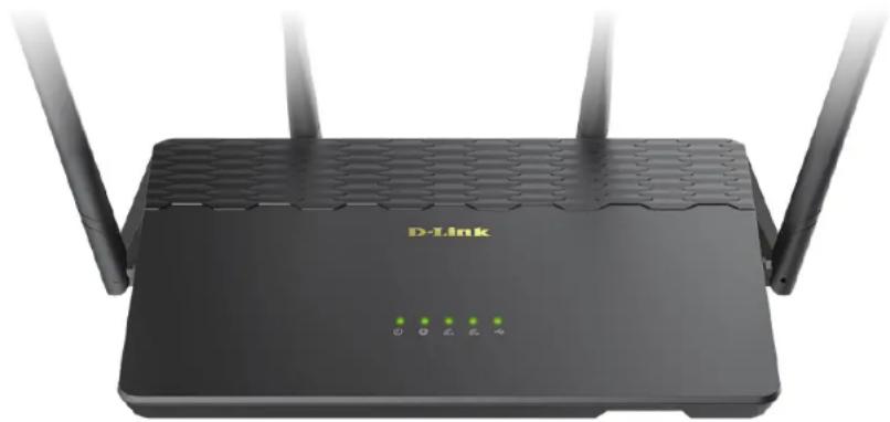
COVR-2600R LED Indicators
natural_image
Black D-Link router with three antennas and a green indicator lights on the front panel (no text or symbols on the device body)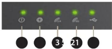
| 1 | Power LED | A solid green light indicates a proper connection to the power supply. The light will be solid orange during boot up. |
| 2 | Internet LED | A solid green light indicates a connection on the Internet port. If the LED is orange, the router cannot connect to the Internet. |
| 3 | Wireless (2.4 GHz LED) | A solid green light indicates that the 2.4 GHz wireless band is enabled. |
| 4 | Wireless (5 GHz LED) A solid green light indicates that the 5 GHz wireless band is enabled. | |
| 5 | USB LED | A solid green light indicates a USB storage device is connected to the USB 3.0 port on the front of the router. |
COVR-1300E LED Indicators

natural_image
3D rendering of a black D-Link router device with four green indicator lights on the front panel (no text or symbols on the device body)
| 1 | Power LED | A solid green light indicates a proper connection to the power supply. The light will be solid orange during boot up. |
| 2 | 2.4 GHz Uplink LED | A solid green light indicates that the 2.4 GHz wireless uplink connection is established. |
| 3 | 5 GHz Uplink LED | A solid green light indicates that the 5 GHz wireless uplink connection is established. |
| 4 | 2.4 GHz Downlink LED | A solid green light indicates that the 2.4 GHz wireless downlink connection is established. |
| 5 | 5 GHz Downlink LED | A solid green light indicates that the 5 GHz wireless downlink connection is established. |
COVR-2600R Back Panel
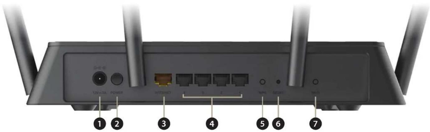
| 1 | Power Connector Connector for the supplied power adapter. | |
| 2 | Power Button Press the power button to power the device on or off. | |
| 3 | INTERNET Port Using an Ethernet cable, connect your broadband modem to this port. | |
| 4 | Gigabit LAN Ports (1- 4) | Connect Ethernet devices such as computers, switches, storage (NAS) devices, and game consoles. |
| 5 | WPS Button | Press to start the WPS process and automatically create an encrypted connection to a WPS client. |
| 6 | Reset Button | Insert a paper clip into the hole, wait for 10 seconds, and release to reset the router to default settings. |
| 7 | Wi-Fi Button | Press this button turn off or turn on the wireless networks. |
COVR-2600R Front Panel

natural_image
Front view of a black wireless router with three Ethernet ports and a USB port, labeled with number 1 (no text or symbols on the device body)1 USB 3.0 Port Connect a USB storage device to share files over the network.
COVR-1300E Back Panel
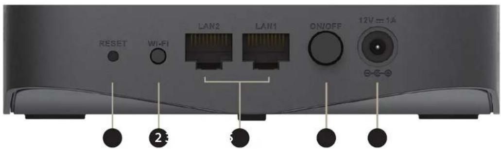
| 1 | Reset Button | Insert a paper clip into the hole, wait for 10 seconds, and release to reset the router to default settings. |
| 2 | Wi-Fi Button Press this button | turn off or turn on the wireless networks. |
| 3 | Gigabit LAN Ports | Connect Ethernet devices such as computers, switches, storage (NAS) devices, and game consoles. |
| 4 | Power Button Press the power | button to power the device on or off. |
| 5 | Power Input Connector for the | supplied power adapter. |
COVR-1300E Side Panel
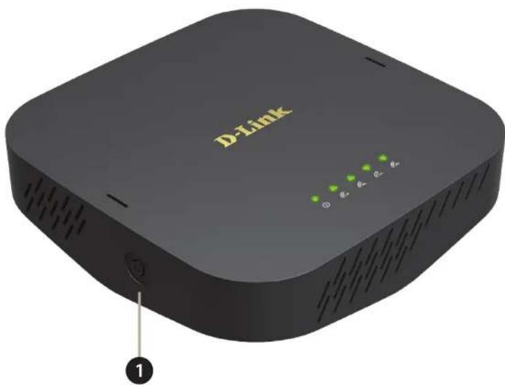
1
WPS Button
Press to start the WPS process and automatically create an encrypted connection to a wireless client.
Installation
This section will walk you through the installation of the COVR-3902. During the setup procedure, your Internet connection will be temporarily unavailable, until the setup process is completed.
Note: If you will be setting up the COVR-3902 AC3900 Whole Home Wi-Fi System on your mobile device using the free D-Link Wi-Fi app, you must download this app before beginning the installation process.
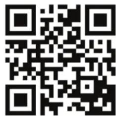
To get the D-Link Wi-Fi app, browse the App Store for Apple devices or the Google Play store and search for D-Link Wi-Fi. You can also scan the QR code below, which will take you to the respective D-Link Wi-Fi app store page directly.


natural_image
Blue square icon with a white Wi-Fi signal symbol (no text or numbers)D-Link Wi-Fi
Before you Begin
- Placement of the router is very important. Do not place the router in an enclosed area such as a closet, cabinet, attic, or garage.
- Configure the router with the computer that was last connected directly to your Internet connection. Verify that it is connected to the Internet before connecting additional devices.
- If your ISP provided you with a modem/router combo, you will need to set it to "bridge" mode so the router can work properly. Please contact your ISP or refer to the user manual for your modem/router device.
- You can only use the Ethernet port on your modem. If you were using the USB connection before using the router, then you must turn off your modem, disconnect the USB cable and connect an Ethernet cable to the Internet port on the router, and then turn the modem back on. In some cases, you may need to call your Internet Service Provider (ISP) to change connection types (USB to Ethernet).
- If connecting to a DSL modem, make sure to have your DSL service information provided by your Internet Service Provider handy. This information is likely to include your DSL account's Username and Password. Your ISP may also supply you with additional WAN configuration settings which might be necessary to establish a connection.
- If you are connecting a considerable amount of networking equipment, it may be a good idea to take the time to label each cable or take a picture of your existing setup before making any changes.
- If you have DSL and are connecting via PPPoE, make sure you disable or uninstall any PPPoE software such as WinPoET, BroadJump, or EnterNet 300 from your computer or you will not be able to connect to the Internet.
Wireless Installation Considerations
The D-Link wireless router lets you access your network using a wireless connection from virtually anywhere within the operating range of your wireless network. Keep in mind that the number, thickness and location of walls, ceilings, or other objects that the wireless signals must pass through may limit the range. Typical ranges vary depending on the types of materials and background RF (radio frequency) noise in your home or business. The key to maximizing wireless range is to follow these basic guidelines:
- Keep the number of walls and ceilings between the D-Link router and other network devices to a minimum - each wall or ceiling can reduce your adapter's range from 3-90 feet (1-30 meters.) Position your devices so that the number of walls or ceilings is minimized.
- Be aware of the direct line between network devices. A wall that is 1.5 feet thick (0.5 meters), at a 45-degree angle appears to be almost 3 feet (1 meter) thick. At a 2-degree angle it looks over 42 feet (14 meters) thick! Position devices so that the signal will travel straight through a wall or ceiling (instead of at an angle) for better reception.
- Building materials make a difference. A solid metal door or aluminum studs may have a negative effect on range. Try to position access points, wireless routers, and computers so that the signal passes through drywall or open doorways. Materials and objects such as glass, steel, metal, walls with insulation, water (fish tanks), mirrors, file cabinets, brick, and concrete will degrade your wireless signal.
- Keep your product away (at least 3-6 feet or 1-2 meters) from electrical devices or appliances that generate RF noise.
- If you are using 2.4 GHz cordless phones or X-10 (wireless products such as ceiling fans, lights, and home security systems), your wireless connection may degrade dramatically or drop completely. Make sure your 2.4 GHz phone base is as far away from your wireless devices as possible. The base transmits a signal even if the phone is not in use.
Hardware Setup
- Attach the four included antennas to the sides and back of the router. The COVR-3902 system is designed to give you the fastest, most stable network connection possible. In order to maximize performance, fully extend the side antennas into a 45-degree angle and the rear antennas into a 90-degree angle to provide optimal wireless coverage. Keep the router in an open area for better wireless coverage.
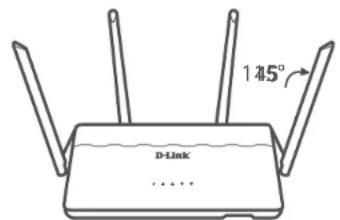
- Position your COVR-2600R router near your Internet-connected modem. Place it in an open area for better wireless coverage.
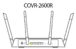

- Connect the supplied power adapter to the router and a power outlet, press the power button, and wait approximately one minute until the Power and 2.4 GHz/5 GHz LED indicators on the front of the device are lit solid green.
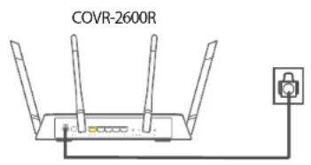
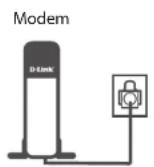
- If you are configuring the COVR-2600R wirelessly from a PC, connect to the Wi-Fi network printed on the included Wi-Fi Configuration Card. You can also find the Wi-Fi network name and password printed on the label attached to the bottom of your router.

flowchart
graph LR
    A["Wi-Fi Configuration Note"] --> B["Laptop"]
    B --> C["COVR-2600R"]
    C --> D["Modem"]
    D --> E["Switch"]
    style A fill:#f9f,stroke:#333
    style B fill:#ccf,stroke:#333
    style C fill:#cfc,stroke:#333
    style D fill:#fcc,stroke:#333
    style E fill:#ffc,stroke:#333
If you are configuring the COVR-2600R from a PC with a wired Ethernet connection, plug one end of an Ethernet cable into the LAN port labeled 1 on the back of the router, and the other end into the Ethernet port on your computer.

Note: This unit is to be used with the included 12 V/3 A power supply.
The COVR-3902 is now ready to be configured using either the web-based user interface, or the free D-Link Wi-Fi mobile app. Proceed to Completing Setup on page 16 for more information on how to complete the setup process.
Completing Setup
There are several different ways you can configure your router to connect to the Internet and connect to your clients:
- D-Link Wi-Fi App - Use your Android device, iPhone, iPad, or iPod touch to configure your router. Refer to D-Link Wi-Fi App on page 17.
- D-Link Setup Wizard - This wizard will launch when you log into the router's web-based user interface for the first time. Refer to Web Interface Setup Wizard on page 24.
- Manual Setup - Log in to the router and manually configure your router. Refer to Configuration on page 31.
D-Link Wi-Fi App
The D-Link Wi-Fi app allows you to install and configure your COVR-3902 AC3900 Whole Home Wi-Fi System from your mobile device.
Note: The screenshots may be different depending on your mobile device's OS version. The following steps show the iOS interface of the D-Link Wi-Fi app. If you are using an Android device, the appearance may be different from that of the screenshots, but the process is the same.


D-Link Wi-Fi
D-Link Wi-Fi App (continued)
Step 1
Open the D-Link Wi-Fi app and tap Add Device.

Step 2
You will be instructed to connect your mobile device to your Covr Wi-Fi network. The default network name (SSID) and password can be found on the included Wi-Fi Configuration Card and on the sticker on the base of the router, and will look something like dlink-XXXX. Once connected, return to the D-Link Wi-Fi app and tap NEXT.


D-Link Wi-Fi (continued)
Step 3
Plug in the COVR-1300E Extender next to the Covr Router and wait approximately 120 seconds for the Extender to boot up. If the Extender is powered on, tap Next.
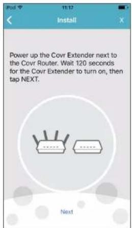
Step 4
When your Covr Extender was successfully detected, a message will appear to confirm. Tap Next to continue.

D-Link Wi-Fi (continued)
Step 5
The D-Link Wi-Fi app will search for your Covr Whole Home Wi-Fi System. Once found, it will display the product details on the screen. Tap Next to continue.
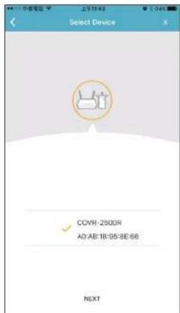
Step 6
Connect the Ethernet cable from your broadband modem to the yellow INTERNET port on the back of the Covr router and follow the on-screen instructions to set up your Internet connection. Tap Next.

D-Link Wi-Fi (continued)
Step 7
Create a Network Name (SSID) and password for your Covr Whole Home Network and tap Next.
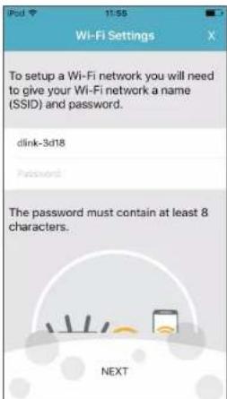
Step 8
Specify an administrator password for your Covr System (note that this should not be the same as your Wi-Fi network password configured in the previous step) and tap Next.
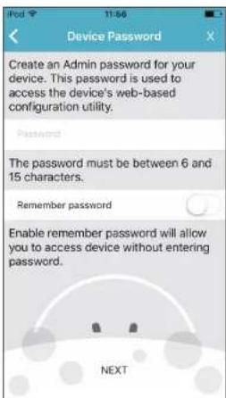
D-Link Wi-Fi (continued)
Step 9
A summary of your network's configuration will be displayed. Tap SAVE to complete the setup process.

Step 10
Unplug the Covr Extender and place it anywhere in your home where the Wi-Fi signal is weak. For optimal performance, make sure all five LEDs on the Extender are solid green. If they are not, place the Extender closer to the router until they do.
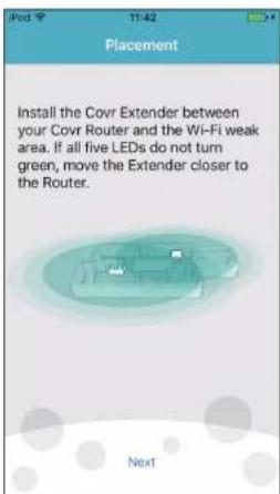
D-Link Wi-Fi (continued)
Step 11
Your Covr Wi-Fi System is now configured and ready to use. You can now connect to the Covr Wi-Fi network listed in the overview. Tap Finish to close the wizard and complete the setup.

Web Interface Setup Wizard
If this is your first time installing the router, open your web browser and enter http://covr.local./ in the address bar. Alternatively, enter the IP address of the router (default: http://192.168.0.1).
The wizard is designed to guide you through a step-by-step process to configure your new D-Link router and connect to the Internet. You can change the language of the setup wizard by selecting a language from the drop-down menu in the lower left.
Click Next to continue.
Step 1
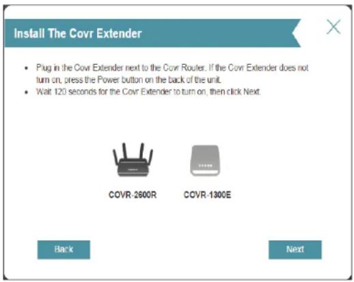
Plug in the Covr Extender next to the Covr Router and wait approximately 120 seconds for the Extender to boot up. When the Extender is powered on, click Next to continue.


Setup Wizard (continued)
Step 2
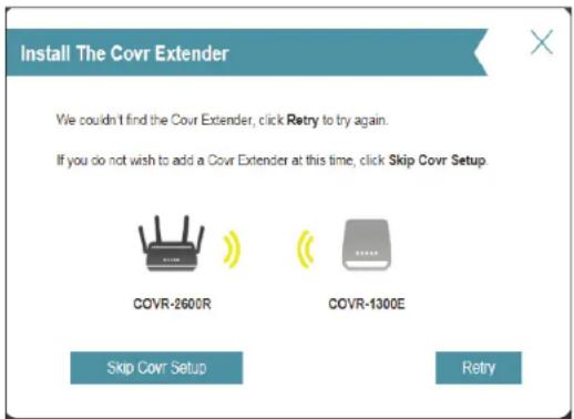
If the Covr Extender could not be detected, click Retry to manually pair the Extender to the Router using WPS (see Step 3 below), or click Skip Covr Setup to skip adding the Extender and continue configuring the router settings.
Step 3
If the system failed to detect the Covr Extender in the previous step and you clicked Retry, you can use WPS to manually pair the devices. Press the WPS button on the left side panel of the Extender within the time limit displayed on the screen. If done correctly, all four wireless LEDs on the Extender will start to flash. If successful, the wizard will automatically continue to the next step.
If pairing through WPS also fails to detect the Extender, try resetting the Extender by holding down the reset button on the back of the device for roughly 10 seconds using an unfolded paper clip. Once reset, run the Setup Wizard again.

Setup Wizard (continued)
Step 4
A message will appear to confirm the Covr Extender was successfully detected and synced to the Covr Router. Click Next to continue.

Step 5
Using an Ethernet cable, connect the yellow port on the back of the Covr Router labeled INTERNET to your modem. Click Next to continue.
The Covr Router will now detect your Internet connection. If your Internet connection was successfully auto-detected, continue to the Step 9. If your connection was not automatically detected, refer to the following steps.

Setup Wizard (continued)
Step 6
If the router does not detect a valid Internet connection, a list of connection types to choose from will be displayed. Choose the connection type you want to use and tap Next. Unless you are connecting to the Internet through PPPoE or your ISP has assigned you a static IP address, select DHCP Connection.

Step 7
If the router detected or you selected PPPoE, enter your PPPoE username and password and click Next to continue.
Note: Make sure to remove your PPPoE software from your computer. The software is no longer needed and will not work through a router.

Setup Wizard (continued)
Step 8
If the router detected or you selected Static, enter the IP and DNS settings supplied by your ISP. Click Next to continue.

Step 9
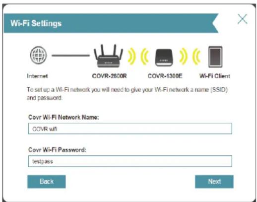
Enter a network name and create a Wi-Fi password (between 8-63 characters) for your Covr Wi-Fi network. Your wireless clients will need to enter this password to be able to connect to your wireless network.
Click Next to continue.
Note: The COVR-3902 uses a single wireless network for both the 2.4 GHz and 5 GHz wireless bands. When connecting clients to the Covr wireless network, they will be automatically added to the best wireless band, either 2.4 GHz or 5 GHz.
Setup Wizard (continued)
Step 10
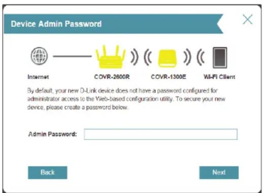
Please enter a new admin password. You will be prompted for this password every time you want to use the router's web configuration utility. Click Next to continue.
Step 11
You will be presented with a summary of your settings. Click Finish to finalize the settings or Back to make changes.

Setup Wizard (continued)
Step 12
Unplug the Covr Extender and place it anywhere in your home where the Wi-Fi signal is weak. For optimal performance, make sure all five LEDs on the Extender are solid green. If they are not, place the Extender closer to the router until they do. Click Finish to complete the Setup Wizard.
Your Covr network is now configured and ready to use!

Configuration - COVR-2600R
To access the configuration utility, open a web-browser such as Internet Explorer and enter http://covr.local./ or you may also connect by typing the IP address of the router (by default this is http://192.168.0.1) in the address bar.
Enter your password. If you previously followed the setup wizard, please use the admin password you entered during the wizard. Otherwise, leave the password blank. Click Log In to proceed.
Note: If you cannot remember your password and cannot log in, press the Reset/WPS button on the back of the device for longer than 10 seconds to restore the router to its default settings.
The router's home page will open, displaying its current connection status.
The bar at the top of the page has quick access to Settings and Management functions. You may quickly jump back Home at any time.
Note: The system will automatically log out after a period of inactivity.

Home
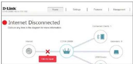
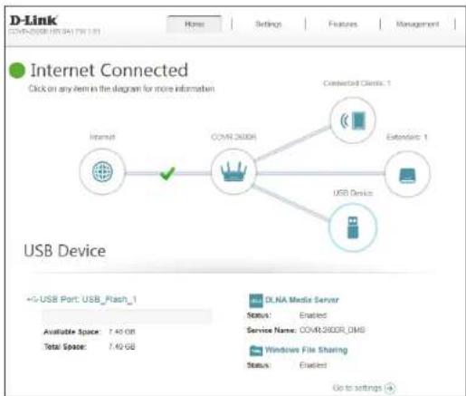
The Home page displays the current status of the router in the form of an interactive diagram. You can click each icon to display information about each part of the network at the bottom of the screen. The menu bar at the top of the page will allow you to quickly navigate to other pages.
The Home page displays whether or not the router is currently connected to the Internet. If it is disconnected, click Click to repair to bring up the setup wizard, refer to Setup Wizard on page 24 for more information.
Internet
To bring up more details about your Internet connection, click on the Internet icon. Click IPv4 or IPv6 to see details of the IPv4 connection and IPv6 connection respectively.
Click Release IP Address to disconnect from the Internet. If you do this and wish to reconnect, click Renew.
To reconfigure the Internet settings, refer to Internet on page 38.

flowchart
graph LR
    A["Internet"] -->|Yes| B["COVR-2600R"]
    B --> C["USB Device"]
    D["Connected Clients 1"] --> E["Device 1"]
    F["External 0"] --> G["Device 0"]

COVR-2600R
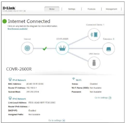
Click on the COVR-2600R icon to view details about the router and its wireless settings.
Here you can see the router's current Wi-Fi network name and password, as well as the router's MAC address, IPv4 address, and IPv6 address.
To reconfigure the network settings, either click Go to settings on the lower left, or click Settings (at the top of the page) and then Network on the menu that appears. Refer to Network on page 71 for more information.
To reconfigure the wireless settings, either click Go to settings, on the lower right, or click Settings (at the top of the page) and then Wireless on the menu that appears. Refer to Wireless on page 68 for more information.
Connected Clients
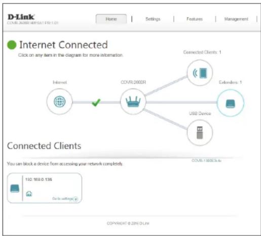
Click on the Connected Clients icon to view details about the clients currently connected to the Covr Wi-Fi system.
On this page you can see all the clients currently connected to the router, and their IP addresses.
To edit each client's settings, click the pencil icon on the client you want to edit.
Name: Displays the name of this client.
Vendor: Displays the vendor of the device.
MAC Address: Displays the MAC address of the device.
IP Address: Displays the current IP address of this client.
Reserve IP: Enable to reserve this IP address for this client.
IP Address Specify an IP address for the COVR-2600R's DHCP server to assign. (Reserved):
Parental Control: Allow or block access to the router.
Schedule: If Parental Control is enabled, use the drop-down menu to select the time schedule that the rule will be enabled for. The schedule may be set to Always Off, or you can create your own schedules in the Schedules section. Refer to Schedule on page 88 for more information.
Click Save when you are done.


Connected Clients (continued)
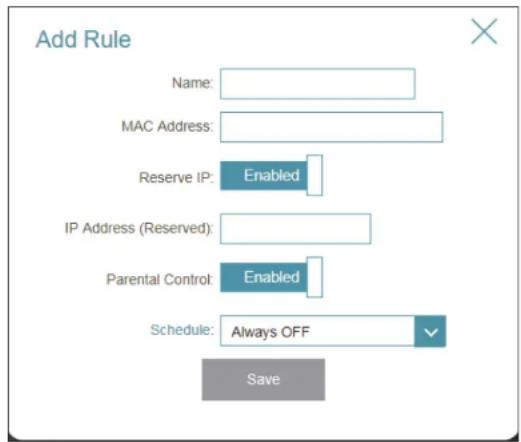
You can also create new client rules, allowing or blocking user-defined clients from accessing your network.
To create a client rule, click the plus icon.
Name: Enter a custom name for this client.
MAC Address: Enter the MAC address of the device.
Reserve IP: Enable to reserve this IP address for this client.
IP Address Specify an IP address for the COVR-2600R's DHCP server to assign. (Reserved):
Parental Control: Allow or block access to the router.
Schedule: If Parental Control is enabled, use the drop-down menu to select the time schedule that the rule will be enabled for. The schedule may be set to Always Off, or you can create your own schedules in the Schedules section. Refer to Schedule on page 88 for more information.
Click Save when you are done.
Extenders
Click on the Extenders icon to view details about all COVR-1300E extenders connected to the COVR-2600R router.
To configure the extender's settings, click Go to settings in the lower right of the client's box, or open a web-browser such as Internet Explorer and enter http://dlinkap.local./ in the address bar. Refer to Configuration - COVR-1300E on page 95 for more information.
USB Device
Click on the USB Device icon to view details about the currently connected USB storage device, DLNA media server, and Windows File Sharing.
If you have a USB device connected, you can see its name and how much free space it has.
To reconfigure the USB sharing settings, either click Go to settings on the lower right, or click Settings (at the top of the page) and then USB Sharing on the menu that appears. Refer to USB Sharing on page 73 for more information.
Settings Wizard
In the Settings menu on the bar on the top of the page, click Wizard to open the setup wizard. This is the same wizard that appears when you start the router for the first time. Refer to Web Interface Setup Wizard on page 24 for details.
Internet
In the Settings menu on the bar at the top of the page, click Internet to see the Internet configuration options.
My Internet Connection Is: Choose your Internet connection type from the drop-down menu. You will be presented with the appropriate options for your connection type. Click Advanced Settings... to expand the list and see all of the options.
For Dynamic IP (DHCP) refer to page 39.
For Static IP refer to page 40.
For PPPoE refer to page 41.
For PPTP refer to page 43.
For L2TP refer to page 45.
For DS-Lite refer to page 47.
To configure an IPv6 connection, click the IPv6 link. Refer to page 48.

Dynamic IP (DHCP)
Select Dynamic IP (DHCP) to obtain IP address information automatically from your Internet Service Provider (ISP). Select this option if your ISP does not specify an IP address to use.
Advanced Settings
Host Name: The host name is optional but may be required by some ISPs. Leave it blank if you are not sure.
Primary DNS Server: Enter the primary DNS server IP address assigned by your ISP. This address is usually obtained automatically from your ISP.
Secondary DNS Server: Enter the secondary DNS server IP address assigned by your ISP. This address is usually obtained automatically from your ISP.
MTU: Maximum Transmission Unit - you may need to change the MTU for optimal performance with your ISP.
MAC Address The default MAC address is set to the Internet port's physical interface Clone: MAC address on the router. You can use the drop-down menu to replace the Internet port's MAC address with the MAC address of a connected client.
Click Save when you are done.

Static IP
Select Static IP if your IP information is provided by your Internet Service Provider (ISP).
IP Address: Enter the IP address provided by your ISP.
Subnet Mask: Enter the subnet mask provided by your ISP.
Default Gateway: Enter the default gateway address provided by your ISP.
Primary DNS Server: Enter the primary DNS server IP address assigned by your ISP.
Advanced Settings
Secondary DNS Server: Enter the secondary DNS server IP address assigned by your ISP.
MTU: Maximum Transmission Unit - you may need to change the MTU for optimal performance with your ISP. Select Manual to define a custom MTU value. The recommended setting is Auto.
MAC Address The default MAC address is set to the Internet port's physical interface Clone: MAC address on the router. You can use the drop-down menu to replace the Internet port's MAC address with the MAC address of a connected client.
Click Save when you are done.



PPPoE
Select PPPoE if your ISP provides and requires you to enter a PPPoE username and password in order to connect to the Internet.
Username: Enter the username provided by your ISP.
Password: Enter the password provided by your ISP.
Reconnect Mode: Select either Always on, On Demand, or Manual.
Maximum Idle Time: Enter a maximum idle time during which the Internet connection is maintained during inactivity. To disable this feature, select Always on as the reconnect mode.
Advanced Settings
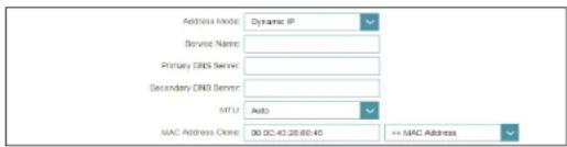
Address Mode: Select Static IP if your ISP assigned you the IP address, subnet mask, gateway, and DNS server addresses. In most cases, select Dynamic IP.
Dynamic IP
Service Name: Enter the ISP service name (optional).
Primary DNS Server: Enter the primary DNS server IP address assigned by your ISP.
Secondary DNS Server: Enter the secondary DNS server IP address assigned by your ISP.
MTU: Maximum Transmission Unit - you may need to change the MTU for optimal performance with your ISP. Select Manual to define a custom MTU value. The recommended setting is Auto.


PPPoE (continued)
MAC Address The default MAC address is set to the Internet port's physical interface Clone: MAC address on the router. You can use the drop-down menu to replace the Internet port's MAC address with the MAC address of a connected client.
Static IP
IP Address: Enter the IP address provided by your ISP.
Service Name: Enter the ISP service name (optional).
Primary DNS Server: Enter the primary DNS server IP address assigned by your ISP.
Secondary DNS Server: Enter the secondary DNS server IP address assigned by your ISP.
MTU: Maximum Transmission Unit - you may need to change the MTU for optimal performance with your ISP. Select Manual to define a custom MTU value. The recommended setting is Auto.

MAC Address The default MAC address is set to the Internet port's physical interface Clone: MAC address on the router. You can use the drop-down menu to replace the Internet port's MAC address with the MAC address of a connected client.
Click Save when you are done.
PPTP
Choose PPTP (Point-to-Point-Tunneling Protocol) if your Internet Service Provider (ISP) uses a PPTP connection. Your ISP will provide you with a username and password.
PPTP Server IP Enter the PPTP server IP address provided by your ISP. Address:
Username: Enter the username provided by your ISP.
Password: Enter the password provided by your ISP.
Reconnect Mode: Select either Always on, On demand, or Manual.
Maximum Idle Time: Enter a maximum idle time during which the Internet connection is maintained during inactivity. To disable this feature, select Always on as the reconnect mode.
Advanced Settings
Address Mode: Select Static IP if your ISP assigned you the IP address, subnet mask, gateway, and DNS server addresses. In most cases, select Dynamic IP.
Dynamic IP
Primary DNS Server: Enter the primary DNS server IP address assigned by your ISP.
Secondary DNS Server: Enter the secondary DNS server IP address assigned by your ISP.
MTU: Maximum Transmission Unit - you may need to change the MTU for optimal performance with your ISP. Select Manual to define a custom MTU value. The recommended setting is Auto.


PPTP (continued)
Static IP
PPTP IP Address: Enter the IP address provided by your ISP.
PPTP Subnet Mask: Enter the subnet mask provided by your ISP.
PPTP Gateway IP Enter the gateway IP address provided by your ISP. Address:
Primary DNS Server: Enter the primary DNS server IP address assigned by your ISP.
Secondary DNS Server: Enter the secondary DNS server IP address assigned by your ISP.
MTU: Maximum Transmission Unit - you may need to change the MTU for optimal performance with your ISP. Select Manual to define a custom MTU value. The recommended setting is Auto.
Click Save when you are done.

L2TP
Choose L2TP (Layer 2 Tunneling Protocol) if your Internet Service Provider (ISP) uses a L2TP connection. Your ISP will provide you with a username and password.
L2TP Server: Enter the L2TP server IP address provided by your ISP.
Username: Enter the username provided by your ISP.
Password: Enter the password provided by your ISP.
Reconnect Mode: Select either Always on, On demand, or Manual.
Maximum Idle Time: Enter a maximum idle time during which the Internet connection is maintained during inactivity. To disable this feature, select Always on as the reconnect mode.
Advanced Settings
Address Mode: Select Static IP if your ISP assigned you the IP address, subnet mask, gateway, and DNS server addresses. In most cases, select Dynamic IP.
Dynamic IP
Primary DNS Server: Enter the primary DNS server IP address assigned by your ISP.
Secondary DNS Server: Enter the secondary DNS server IP address assigned by your ISP.
MTU: Maximum Transmission Unit - you may need to change the MTU for optimal performance with your ISP. Select Manual to define a custom MTU value. The recommended setting is Auto.


L2TP (continued)
Static IP
L2TP IP Address: Enter the IP address provided by your ISP.
L2TP Subnet Mask: Enter the subnet mask provided by your ISP.
L2TP Gateway IP Enter the gateway IP address provided by your ISP. Address:
Primary DNS Server: Enter the primary DNS server IP address assigned by your ISP.
Secondary DNS Server: Enter the secondary DNS server IP address assigned by your ISP.
MTU: Maximum Transmission Unit - you may need to change the MTU for optimal performance with your ISP. Select Manual to define a custom MTU value. The recommended setting is Auto.
Click Save when you are done.

DS-Lite
DS-Lite is an IPv6 connection type. After selecting DS-Lite, the following parameters will be available for configuration:
Advanced Settings
DS-Lite Select DS-Lite DHCPv6 Option to let the router allocate the AFTR Configuration: IPv6 address automatically. Select Manual Configuration to enter the AFTR IPv6 address manually.
B4 IPv4 Address: Enter the B4 IPv4 address value used here.
WAN IPv6 Once connected, the WAN IPv6 address will be displayed here. Address:
IPv6 WAN Default Once connected, the IPv6 WAN default gateway address will be Gateway: displayed here.
Manual Configuration
AFTR IPv6 Enter the AFTR IPv6 address used here. Address:
B4 IPv4 Address: Enter the B4 IPv4 address value used here.
WAN IPv6 Once connected, the WAN IPv6 address will be displayed here. Address:
IPv6 WAN Default Once connected, the IPv6 WAN default gateway address will be Gateway: displayed here.
Click Save when you are done.


IPv6
To configure an IPv6 connection, click the IPv6 link. To return to the IPv4 settings, click IPv4.
My Internet Connection Is: Choose your IPv6 connection type from the drop-down menu. You will be presented with the appropriate options for your connection type. Click Advanced Settings... to expand the list and see all of the options.
For Auto Detection refer to page 49.
For Static IPv6 refer to page 51.
For Auto Configuration (SLAAC/DHCPv6) refer to page 53.
For PPPoE refer to page 56.
For IPv6 in IPv4 Tunnel refer to page 60.
For 6to4 refer to page 63.
For 6rd refer to page 65.
For Local Connectivity Only refer to page 67.

Auto Detection
Select Auto Detection to automatically detect the IPv6 connection method used by your Internet Service Provider (ISP). If Auto Detection fails, you can manually select another IPv6 connection type.
IPv6 DNS Settings
DNS Type: Select either Obtain DNS server address automatically or Use the following DNS address.
If Use the following DNS address is selected:
Primary DNS If you selected Use the following DNS address above, enter the Server: primary DNS server address.
Secondary DNS If you selected Use the following DNS address above, enter the Server: secondary DNS server address.
LAN IPv6 Address Settings
LAN IPv6 Address: Displays the currently assigned LAN IPv6 address.
LAN IPv6 Link- Displays the router's LAN link-local address. Local Address:


Auto Detection (continued)
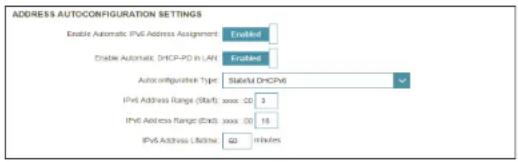
Advanced Settings - Address Autoconfiguration Settings
Enable Automatic Enable or disable the Automatic IPv6 Address Assignment feature.
IPv6 Address
Assignment:
Enable Automatic Enable or disable DHCP-PD for other IPv6 routers connected to the DHCP-PD in LAN: LAN interface.
Note: This feature requires a smaller subnet prefix than /64 (i.e. allowing for a larger address allocation), such as /63. Contact your ISP for more information.
Autoconfiguration Select SLAAC+RDNSS, SLAAC+Stateless DHCP, or Stateful DHCPv6. Type:
If you selected SLAAC+RDNSS or SLAAC+Stateless DHCP as the Autoconfiguration Type:
Router This value is auto-configured with this combination.
Advertisement
Lifetime:
If you selected Stateful DHCPv6 as the Autoconfiguration Type:
IPv6 Address Enter the starting IPv6 address for the DHCP server's IPv6 assignment. Range (Start):
IPv6 Address Enter the ending IPv6 address for the DHCP server's IPv6 assignment. Range (End):
IPv6 Address This value is auto-configured with this combination. Lifetime:
Click Save when you are done.


Static IPv6
Select Static IP if your IPv6 information is provided by your Internet Service Provider (ISP).
Use Link-Local Enable or disable link-local address use. Address:
Default Gateway: Enter the default gateway for your IPv6 connection.
Primary DNS Server: Enter the primary DNS server address.
Secondary DNS Server: Enter the secondary DNS server address.
If Use Link-Local Address is disabled these additional parameters are available for configuration:
IPv6 Address: Enter the address supplied by your ISP.
Subnet Prefix Enter the subnet prefix length supplied by your ISP. Length:
LAN IPv6 Address Settings
LAN IPv6 Address: Enter the LAN (local) IPv6 address for the router.
LAN IPv6 Link- Displays the router's LAN link-local address. Local Address:


Static IPv6 (continued)
Advanced Settings - Address Autoconfiguration Settings
Enable Automatic Enable or disable the Automatic IPv6 Address Assignment feature. IPv6 Address Assignment:
Autoconfiguration Select SLAAC+RDNSS, SLAAC+Stateless DHCP, or Stateful DHCPv6. Type:
If you selected SLAAC+RDNSS or SLAAC+Stateless DHCP as the Autoconfiguration Type:
Router Enter the router advertisement lifetime (in minutes). Advertisement Lifetime:
If you selected Stateful DHCPv6 as the Autoconfiguration Type:
IPv6 Address Enter the starting IPv6 address for the DHCP server's IPv6 assignment. Range (Start):
IPv6 Address Enter the ending IPv6 address for the DHCP server's IPv6 assignment. Range (End):
IPv6 Enter the IPv6 address lifetime (in minutes). Advertisement Lifetime:
Click Save when you are done.


Auto Configuration (SLAAC/DHCPv6)
Select Auto Configuration if your ISP assigns your IPv6 address when your router requests one from the ISP's server. Some ISPs require you to adjust settings on your side before your router can connect to the IPv6 Internet.
IPv6 DNS Settings
DNS Type: Select either Obtain DNS server address automatically or Use the following DNS address.
If Use the following DNS address is selected:
Primary DNS Server: Enter the primary DNS server address.
Secondary DNS Server: Enter the secondary DNS server address.
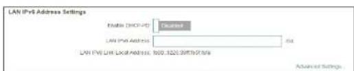
LAN IPv6 Address Settings
Enable DHCP-PD: Enable or disable prefix delegation services.
LAN IPv6 Link- Displays the router's LAN link-local address. Local Address:
If Enable DHCP-PD is disabled, these additional parameters are available for configuration:
LAN IPv6 Address: Enter a valid LAN IPv6 address.
LAN IPv6 Link- Displays the router's LAN link-local address. Local Address:



Auto Configuration (SLAAC/DHCPv6) (continued)
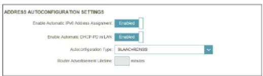
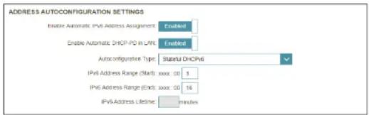
Advanced Settings - Address Autoconfiguration Settings
Enable Automatic Enable or disable the Automatic IPv6 Address Assignment feature. IPv6 Address Assignment:
If DHCP-PD is enabled in LAN IPv6 Address Settings:
Enable Automatic Enable or disable DHCP-PD for other IPv6 routers connected to the DHCP-PD in LAN: LAN interface.
Note: This feature requires a smaller subnet prefix than /64 (i.e. allowing for a larger address allocation), such as /63. Contact your ISP for more information.
Autoconfiguration Select SLAAC+RDNSS, SLAAC+Stateless DHCP, or Stateful DHCPv6. Type:
If you selected SLAAC+RDNSS or SLAAC+Stateless DHCP as the Autoconfiguration Type:
Router This value is auto-configured with this combination. Advertisement Lifetime:
If you selected Stateful DHCPv6 as the Autoconfiguration Type:
IPv6 Address Enter the starting IPv6 address for the DHCP server's IPv6 assignment. Range (Start):
IPv6 Address Enter the ending IPv6 address for the DHCP server's IPv6 assignment. Range (End):
IPv6 Address This value is auto-configured with this combination. Lifetime:

Auto Configuration (SLAAC/DHCPv6) (continued)
If DHCP-PD is disabled in LAN IPv6 Address Settings and SLAAC+Stateless DHCP or SLAAC+RDNSS is chosen as the Autoconfiguration Type:

Router This value is auto-configured with this combination. Advertisement Lifetime:
If DHCP-PD is disabled in LAN IPv6 Address Settings and Stateful DHCPv6 is chosen as the Autoconfiguration Type:
IPv6 Address Enter the starting IPv6 address for the DHCP server's IPv6 assignment. Range (Start):
IPv6 Address Enter the ending IPv6 address for the DHCP server's IPv6 assignment. Range (End):
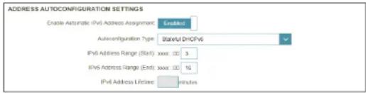
IPv6 This value is automatically received from the DHCP Prefix Delegation. Advertisement Lifetime:
Click Save when you are done.
PPPoE
Select PPPoE if your ISP provides and requires you to enter a PPPoE username and password in order to connect to the Internet.
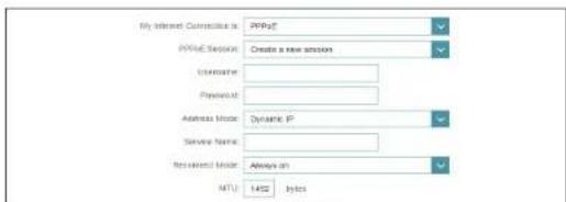
PPPoE Session: Choose Share with IPv4 to re-use your IPv4 PPPoE username and password, or Create a new session.
Address Mode Select Static IP if your ISP assigned you an IP address. In most cases, select Dynamic IP.
If you selected Static IP as the Address Mode and Share with IPv4 as the PPPoE Session:
IP Address: Enter the IP address provided by your ISP.
If you selected Create a new session as the PPPoE Session:
Username: Enter the username provided by your ISP.
Password: Enter the password provided by your ISP.
Address Mode: Select either Dynamic IP or Static IP.
Service Name: Enter the ISP service name (optional).
Reconnect Mode Select either Always On or Manual.
MTU Maximum Transmission Unit - you may need to change the MTU for optimal performance with your ISP.
If you selected Static IP as the Address Mode and Create a new session as the PPPoE Session:
IP Address Enter the IP address provided by your ISP.
Service Name Enter the ISP service name (optional).


PPPoE (continued)
Reconnect Mode Select either Always-on or Manual.
MTU Maximum Transmission Unit - you may need to change the MTU for optimal performance with your ISP.
IPv6 DNS Settings
DNS Type: Select either Obtain DNS server address automatically or Use the following DNS address.
If Use the following DNS address is selected:
Primary DNS Server: Enter the primary DNS server address.
Secondary DNS Server: Enter the secondary DNS server address.
LAN IPv6 Address Settings
Enable DHCP-PD: Enable or disable prefix delegation services. This option is only available if you selected Dynamic IP for address mode.
LAN IPv6 Link- Displays the router's LAN link-local address.
Local Address:
If Enable DHCP-PD is disabled or when the Address Mode is set to Static IP, this additional parameter is available for configuration:
LAN IPv6 Address: Enter the LAN (local) IPv6 address for the router.





PPPoE (continued)
LAN IPv6 Link- Displays the router's LAN link-local address.
Local Address:
Advanced Settings - Address Autoconfiguration Settings
Enable Automatic Enable or disable the Automatic IPv6 Address Assignment feature.
IPv6 Address
Assignment:
If DHCP-PD is enabled in LAN IPv6 Address Settings:
Enable Automatic Enable or disable DHCP-PD for other IPv6 routers connected to the DHCP-PD in LAN: LAN interface. This option is not available if the Address Mode is set to Static IP.
Note: This feature requires a smaller subnet prefix than /64 (i.e. allowing for a larger address allocation), such as /63. Contact your ISP for more information.
Autoconfiguration Select SLAAC+RDNSS, SLAAC+Stateless DHCP, or Stateful DHCPv6. Type:
If you selected SLAAC+RDNSS or SLAAC+Stateless DHCP as the Autoconfiguration Type:


Router This value is auto-configured with this combination.
Advertisement
Lifetime:
PPPoE (continued)
If you selected Stateful DHCPv6 as the Autoconfiguration Type:
IPv6 Address Enter the starting IPv6 address for the DHCP server's IPv6 assignment. Range (Start):
IPv6 Address Enter the ending IPv6 address for the DHCP server's IPv6 assignment. Range (End):
IPv6 Address This value is auto-configured with this combination. Lifetime:
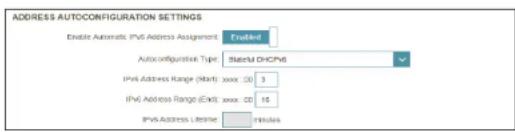
If DHCP-PD is disabled in LAN IPv6 Address Settings and SLAAC+Stateless DHCP or SLAAC+RDNSS is chosen as the Autoconfiguration Type:
Router This value is auto-configured with this combination. Advertisement Lifetime:
If DHCP-PD is disabled in LAN IPv6 Address Settings and Stateful DHCPv6 is chosen as the Autoconfiguration Type:
IPv6 Address Enter the starting IPv6 address for the DHCP server's IPv6 assignment. Range (Start):
IPv6 Address Enter the ending IPv6 address for the DHCP server's IPv6 assignment. Range (End):
IPv6 This value is automatically received from the DHCP Prefix Delegation. Advertisement Lifetime:
Click Save when you are done.


IPv6 in IPv4 Tunnel
The user can configure the IPv6 connection to run in IPv4 Tunnel mode. IPv6 over IPv4 tunnelling encapsulates IPv6 packets in IPv4 packets so that IPv6 packets can be sent over an IPv4 infrastructure.
Remote IPv4 Enter the IPv4 remote address you will use. Address:
Remote IPv6 Enter the IPv6 remote address you will use. Address:
Local IPv4 Displays the current local IPv4 address. Address:
Local IPv6 Enter the IPv6 local address you will use. Address:
Subnet Prefix Enter the subnet prefix length supplied by your ISP. Length:

IPv6 DNS Settings
DNS Type: Select either Obtain DNS server address automatically or Use the following DNS address.
If Use the following DNS address is selected:
Primary DNS Server: Enter the primary DNS server address.
Secondary DNS Server: Enter the secondary DNS server address.


IPv6 in IPv4 Tunnel (continued)
LAN IPv6 Address Settings
Enable DHCP-PD: Enable or disable prefix delegation services. This option is only available if you selected Dynamic IP for address mode.
LAN IPv6 Link- Displays the router's LAN link-local address.
Local Address:
If Enable DHCP-PD is disabled, these additional parameters are available for configuration:
LAN IPv6 Address: If DHCP-PD disabled, enter the LAN (local) IPv6 address for the router.
LAN IPv6 Link- Displays the router's LAN link-local address.
Local Address:


Advanced Settings - Address Autoconfiguration Settings
Enable Automatic Enable or disable the Automatic IPv6 Address Assignment feature. IPv6 Address Assignment:
If DHCP-PD is enabled in LAN IPv6 Address Settings:
Enable Automatic Enable or disable DHCP-PD for other IPv6 routers connected to the DHCP-PD in LAN: LAN interface.
Note: This feature requires a smaller subnet prefix than /64 (i.e. allowing for a larger address allocation), such as /63. Contact your ISP for more information.
Autoconfiguration Select SLAAC+RDNSS, SLAAC+Stateless DHCP, or Stateful DHCPv6. Type:

IPv6 in IPv4 Tunnel (continued)
If you selected SLAAC+RDNSS or SLAAC+Stateless DHCP as the Autoconfiguration Type:
Router Enter the router advertisement lifetime (in minutes). Advertisement Lifetime:
If you selected Stateful DHCPv6 as the Autoconfiguration Type:
IPv6 Address Enter the starting IPv6 address for the DHCP server's IPv6 assignment. Range (Start): IPv6 Address Enter the ending IPv6 address for the DHCP server's IPv6 assignment. Range (End):
If DHCP-PD is disabled in LAN IPv6 Address Settings and SLAAC+Stateless DHCP or SLAAC+RDNSS is chosen as the Autoconfiguration Type:
Router Enter the router advertisement lifetime (in minutes). Advertisement Lifetime:
If DHCP-PD is disabled in LAN IPv6 Address Settings and Stateful DHCPv6 is chosen as the Autoconfiguration Type:
IPv6 Address Enter the starting IPv6 address for the DHCP server's IPv6 assignment. Range (Start):
IPv6 Address Enter the ending IPv6 address for the DHCP server's IPv6 assignment. Range (End):
IPv6 Enter the IPv6 address lifetime (in minutes). Advertisement Lifetime:
Click Save when you are done.


6to4
In this section the user can configure the IPv6 6 to 4 connection settings. 6to4 is an IPv6 address assignment and automatic tunneling technology that is used to provide unicast IPv6 connectivity between IPv6 sites and hosts across the IPv4 Internet.
6to4 Address: Displays the 6 to 4 address.
6to4 Relay: Enter the 6 to 4 relay supplied by your ISP.
Primary DNS Server: Enter the primary DNS server address.
Secondary DNS Server: Enter the secondary DNS server address.
LAN IPv6 Address Settings
LAN IPv6 Address: Enter the LAN (local) IPv6 address for the router.
LAN IPv6 Link- Displays the router's LAN link-local address. Local Address:

6to4 (continued)
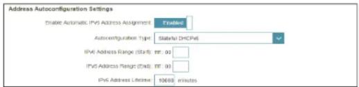
Advanced Settings - Address Autoconfiguration Settings
Enable Automatic Enable or disable the Automatic IPv6 Address Assignment feature.
IPv6 Address
Assignment:
Autoconfiguration Select SLAAC+RDNSS, SLAAC+Stateless DHCP, or Stateful DHCPv6. Type:
If you selected SLAAC+RDNSS or SLAAC+Stateless DHCP as the Autoconfiguration Type:
Router This value is auto-configured with this combination.
Advertisement
Lifetime:
If you selected Stateful DHCPv6 as the Autoconfiguration Type:
IPv6 Address Enter the starting IPv6 address for the DHCP server's IPv6 assignment.
Range (Start):
IPv6 Address Enter the ending IPv6 address for the DHCP server's IPv6 assignment.
Range (End):
IPv6 Address This value is auto-configured with this combination.
Lifetime:
Click Save when you are done.


6rd
In this section the user can configure the IPv6 6rd connection settings.
Assign IPv6 Prefix: Currently unsupported.
Primary DNS Server: Enter the primary DNS server address.
Secondary DNS Server: Enter the secondary DNS server address.
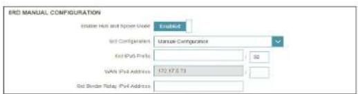
6rd Manual Configuration
Enable Hub and Spoke Mode: Enable this option if you want to minimize the number of routes to the destination by using a hub and spoke method of networking.
6rd Configuration: Choose the 6rd DHCPv4 Option to automatically discover and populate the data values, or Manual Configuration to enter the settings yourself.
If you selected Manual configuration
6rd IPv6 Prefix: Enter the 6rd IPv6 prefix and mask length supplied by your ISP.
WAN IPv4 Displays the router's IPv4 address. Enter the IPv4 subnet mask length Address: provided by your ISP.
6rd Border Relay Enter the 6rd border relay IPv4 address supplied by your ISP. IPv4 Address:
LAN IPv6 Address Settings
LAN IPv6 Address: Displays the router's LAN IPv6 address link-local address.
LAN IPv6 Link- Displays the router's LAN link-local address. Local Address:



6rd (continued)
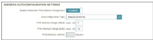
Advanced Settings - Address Autoconfiguration Settings
Enable Automatic Enable or disable the Automatic IPv6 Address Assignment feature.
IPv6 Address
Assignment:
Autoconfiguration Select SLAAC+RDNSS, SLAAC+Stateless DHCP, or Stateful DHCPv6. Type:
If you selected SLAAC+RDNSS or SLAAC+Stateless DHCP as the Autoconfiguration Type:
Router This value is auto-configured with this combination.
Advertisement
Lifetime:
If you selected Stateful DHCPv6 as the Autoconfiguration Type:
IPv6 Address Enter the starting IPv6 address for the DHCP server's IPv6 assignment.
Range (Start):
IPv6 Address Enter the ending IPv6 address for the DHCP server's IPv6 assignment.
Range (End):
IPv6 Address This value is auto-configured with this combination.
Lifetime:
Click Save when you are done.



Local Connectivity Only
Local Connectivity Only allows you to set up an IPv6 connection that will not connect to the Internet.
Advanced Settings
IPv6 ULA Settings
Enable ULA: Click to enable Unique Local IPv6 Unicast Addresses settings.
Use Default ULA If Enable ULA is selected, enable this option to use the default ULA Prefix: prefix.
If you selected Enable ULA and disabled Default ULA Prefix:
ULA Prefix: Enter your own ULA prefix.
Current IPv6 ULA Settings
Current ULA Displays the current ULA prefix. Prefix:
LAN IPv6 ULA: Displays the LAN's IPv6 ULA.
Click Save when you are done.


Wireless
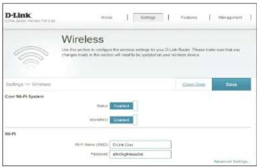
From this page you can configure your Covr wireless network settings.
Covr Wi-Fi System
Status: Indicates the status of the seamless Covr Wi-Fi system. This feature cannot be disabled.
MU-MIMO: Click to enable or disable Multi-User Multiple Input Multiple Output (MU-MIMO). Enabling this feature will allow the router to communicate with multiple devices at once for faster and more efficient throughput. It is recommend to leave this feature enabled.
Wi-Fi
Wi-Fi Name (SSID): Enter a name for your Covr Wi-Fi network.
Password: Create a password to use for wireless security. Wireless clients will need to enter this password to successfully connect to the network.
Advanced Settings
Security Mode: Select the wireless security mode. Currently, only WPA/WPA2-Personal is supported.
Transmission Power: Select the desired wireless transmission power.
Schedule: Use the drop-down menu to select the time schedule that the Wi-Fi network will be enabled for. The schedule may be set to Always Enable, or you can create your own schedules in the Schedules section. Refer to Schedule on page 88 for more information.

Wireless (continued)
Wi-Fi Protected Setup
The easiest way to connect your wireless devices to the router is with Wi-Fi Protected Setup (WPS). Using WPS-PIN is disabled by default due to security vulnerabilities.
WPS-PBC Status: Enable or disable WPS-PBC (Push Button Configuration) functionality.
WPS-PIN Status: Enable or disable WPS-PIN functionality.
Click Save when you are done.

Guest Zone
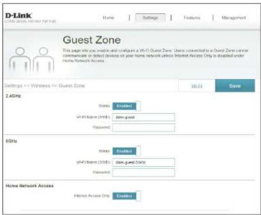
The Guest Zone feature will allow you to create temporary zones that can be used by guests to access the Internet. These zones will be separate from your main wireless network. You may configure different zones for the 2.4 GHz and 5 GHz wireless bands.
In the Settings menu on the bar on the top of the page, click Wireless, then click the Guest Zone link.
2.4 GHz / 5 GHz
Status: Enable or disable the 2.4 GHz / 5 GHz wireless guest network.
Wi-Fi Name (SSID): Create a name for your wireless network using up to 32 characters.
Password: Create a password to use for wireless security.
Home Network Access
Internet Access Enabling this option will confine connectivity to the Internet, Only: preventing guests from accessing other local network devices.
Click Save when you are done.
Network
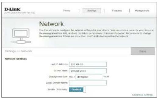
This section will allow you to change the local network settings of the router and to configure the DHCP settings. In the Settings menu on the bar on the top of the page, click Network. Click Advanced Settings... to expand the list and see all of the options.
Network Settings
LAN IP Address: Enter the IP address of the router. The default IP address is 192.168.0.1. If you change the IP address, once you click Save, you will need to enter the new IP address in your browser to get back into the configuration utility.
Subnet Mask: Enter the subnet mask of the router. The default subnet mask is 255.255.255.0.
Management The default address to access the router's configuration is Link: http://dlinkrouter.local/ Here, you can replace dlinkrouter with a name of your choice.
Local Domain Enter the domain name (optional). Name:
Enable DNS Relay: Disable to transfer the DNS server information from your ISP to your computers. If enabled, your computers will use the router for a DNS server.
Network (continued)
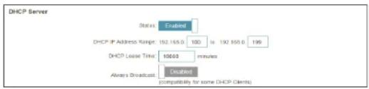
DHCP Server
Status: Enable or disable the DHCP server.
DHCP IP Address Enter the starting and ending IP addresses for the DHCP server's IP Range: assignment.
Note: If you statically (manually) assign IP addresses to your computers or devices, make sure the IP addresses are outside of this range or you may have an IP conflict.
DHCP Lease Time: Enter the length of time for the IP address lease (in minutes).
Always Broadcast: Enable this feature to broadcast your network's DHCP server to LAN/WLAN clients.
Advanced Settings
WAN Port Speed: You may set the port speed of the Internet port to 10 Mbps, 100 Mbps, 1000 Mbps, or Auto (recommended).
UPnP: Enable or disable Universal Plug and Play (UPnP). UPnP provides compatibility with networking equipment, software, and peripherals.
IPv4 Multicast Enable to allow IPv4 multicast traffic to pass through the router from Stream: the Internet.
IPv6 Multicast Enable to allow IPv6 multicast traffic to pass through the router from Stream: the Internet.
Click Save when you are done.

USB Sharing
This page will allow you to set up access to files on an external USB drive plugged into the router. You can access shared files through the local network or from the Internet using a web browser or an app on your mobile device. In the Settings menu on the bar on the top of the page, click USB Sharing.
UPnP Media Server
Status: Enable or disable the UPnP media server function, allowing connected clients access to media files over the network.
UPnP Media Choose a name for your UPnP media server so that it can be found. Server:
Windows File Sharing (SAMBA)
Status: Enable or disable the Windows file sharing function, allowing connected clients access to shared files over the network.
Windows File Sharing: Choose Require router's admin password to require clients to enter the admin password in order to access the shared media, or choose Allow all users to access (no password) to allow clients full access to the shared media.
Click Save when you are done.

Features QoS Engine
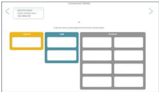
This Quality of Service (QoS) Engine will allow you to prioritize particular clients over others, so that those clients receive higher bandwidth. For example, if one client is streaming a movie and another is downloading a non-urgent file, you might wish to assign the former device a higher priority than the latter so that the movie streaming is not disrupted by the traffic of the other devices on the network.
In the Features menu on the bar on the top of the page, click QoS Engine.
Under Connected Clients, you will see device cards representing each connected client. If some are off-screen, you can use the < and > buttons to scroll through the cards.
A maximum of one device can be assigned Highest priority.
A maximum of two devices can be assigned High priority.
A maximum of eight devices can be assigned Medium priority.
If no devices are explicitly assigned a priority, they will all be treated with equal priority. If some devices are not assigned a priority and others are, the unassigned devices will be treated with the lowest priority.
To assign a priority level to a device, drag the device card from the All Devices list over an empty slot and release the mouse button. The card will remain in the slot. If you want to remove a priority assignment from a device and return it to the All Devices list, click the cross (x) icon in the top right of the device card.
Click Save when you are done.

flowchart
graph TD
    A["High"] --> B["Low"]
    B --> C["Medium"]
    style A fill:#FFD700,stroke:#333
    style B fill:#4CAF50,stroke:#333
    style C fill:#90EE90,stroke:#333
Firewall
The router's firewall protects your network from malicious attacks over the Internet. In the Features menu on the bar on the top of the page, click Firewall. Click Advanced Settings... to expand the list and see all of the options.
Enable DMZ: Enable or disable Demilitarized Zone (DMZ). This completely exposes the client to threats over the Internet, and is not recommended in ordinary situations.
DMZ IP Address: If you enabled DMZ, enter the IP address of the client you wish to expose, or use the drop-down menu to quickly select it.
Enable SPI IPv4: Enabling Stateful Packet Inspection (SPI) helps to prevent cyber attacks by validating that the traffic passing through the session conforms to the protocol.
Enable Anti-Spoof Enable this feature to help protect your network from certain kinds Checking: of "spoofing" attacks.
IPv6 Simple Security: Enable or disable IPv6 Simple Security. Enabling this feature will cause the router to automatically configure rules for allowing or denying several types of incoming and outgoing IPv6 traffic based on a set of rules defined in the RFC-6092 standard.
IPv6 Ingress If IPv6 Simple Security is disabled, click to enable or disable IPv6 Filtering: ingress filtering. Enabling this feature will cause the router to scan and verify incoming IPv6 traffic and filter out any suspicious packets.


Firewall Settings (continued)
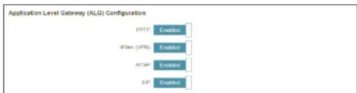
Advanced Settings - Application Level Gateway (ALG) Configuration
PPTP: Allows multiple machines on the LAN to connect to their corporate network using the PPTP protocol.
IPSec (VPN): Allows multiple VPN clients to connect to their corporate network using IPSec. Some VPN clients support traversal of IPSec through NAT. This Application Level Gateway (ALG) may interfere with the operation of such VPN clients. If you are having trouble connecting with your corporate network, try turning this ALG off. Please check with the system administrator of your corporate network whether your VPN client supports NAT traversal.
RTSP: Allows applications that uses Real Time Streaming Protocol (RTSP) to receive streaming media from the Internet.
SIP: Allows devices and applications using VoIP (Voice over IP) to communicate across NAT. Some VoIP applications and devices have the ability to discover NAT devices and work around them. This ALG may interfere with the operation of such devices. If you are having trouble making VoIP calls, try turning this ALG off.
Click Save when you are done.
IPv4/IPv6 Rules
The IPv4/IPv6 Rules section is an advanced option that lets you configure what kind of traffic is allowed to pass through the network. To configure the IPv4 rules, from the Firewall Settings page click IPv4 Rules. To configure IPv6 rules, from the Firewall Settings page click IPv6 Rules. To return to the main Firewall Settings page, click Advanced.
To begin, use the drop-down menu to select whether you want to ALLOW or DENY the rules you create. You can also choose to turn filtering OFF.
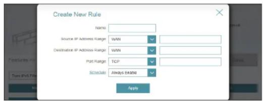
If you wish to remove a rule, click on its trash can icon in the Delete column. If you wish to edit a rule, click on its pencil icon in the Edit column. If you wish to create a new rule, click the Add Rule button. Click Save when you are done. If you edit or create a rule, the following options will appear:
Name: Enter a name for the rule.
Source IP Address Enter the source IP address range that the rule will apply to, and using Range: the drop-down menu, specify whether it is a WAN or LAN IP address.
Destination IP Enter the destination IP address range that the rule will apply to, and Address Range: using the drop-down menu, specify whether it is a WAN or LAN IP address.
Port Range: Select the protocol of the traffic to allow or deny (Any, TCP, or UDP) and then enter the range of ports that the rule will apply to.
Schedule: Use the drop-down menu to select the time schedule that the rule will be enabled for. The schedule may be set to Always Enable, or you can create your own schedules in the Schedules section. Refer to Refer to Schedule on page 88 for more information.
Click Apply when you are done.

Port Forwarding
Port forwarding allows you to specify a port or range of ports to open for specific devices on the network. This might be necessary for certain applications to connect through the router. In the Features menu on the bar on the top of the page, click Port Forwarding.
If you wish to remove a rule, click on its trash can icon in the Delete column. If you wish to edit a rule, click on its pencil icon in the Edit column. If you wish to create a new rule, click the Add Rule button. Click Save when you are done. If you edit or create a rule, the following options will appear:
Name: Enter a name for the rule.
Local IP: Enter the IP address of the computer on your local network that you want to allow the incoming service to. Alternatively, select the device from the drop-down menu.
TCP Port: Enter the TCP ports that you want to open. You can enter a single port or a range of ports. Separate ports with a comma (for example: 24,1009,3000-4000).
UDP Port: Enter the UDP ports that you want to open. You can enter a single port or a range of ports. Separate ports with a comma (for example: 24,1009,3000-4000).
Schedule: Use the drop-down menu to select the time schedule that the rule will be enabled for. The schedule may be set to Always Enable, or you can create your own schedules in the Schedules section. Refer to Schedule on page 88 for more information.
Click Apply when you are done.


Virtual Server
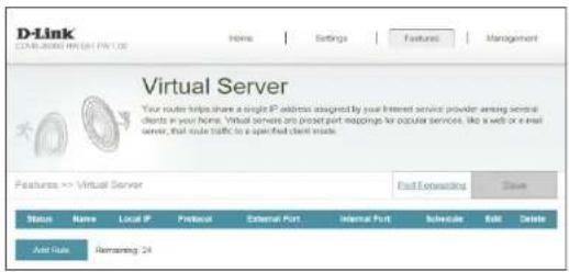
The virtual server allows you to specify a single public port on your router for redirection to an internal LAN IP address and Private LAN port. To configure the virtual server, from the Port Forwarding page click Virtual Server. To return to the main Port Forwarding page, click Port Forwarding.
If you wish to remove a rule, click on its trash can icon in the Delete column. If you wish to edit a rule, click on its pencil icon in the Edit column. If you wish to create a new rule, click the Add Rules button. Click Save when you are done. If you edit or create a rule, the following options will appear:
Name: Enter a name for the rule. Alternatively, select the protocol/Application from the drop-down menu.
Local IP: Enter the IP address of the computer on your local network that you want to allow the incoming service to. Alternatively, select the device from the drop-down menu.
Protocol: Select the protocol of the traffic to allow or deny (TCP, UDP, Both, or Other).
Protocol Number: If you entered Other above, enter the protocol number.
External Port: Enter the public port you want to open.
Internal Port: Enter the private port you want to open.
Schedule: Use the drop-down menu to select the time schedule that the rule will be enabled for. The schedule may be set to Always Enable, or you can create your own schedules in the Schedules section. Refer to Schedule on page 88 for more information.
Click Apply when you are done.

Website Filter
The website filter settings allow you to block access to certain web sites. You can either create a list of sites to block, or create a list of sites to allow (with all other sites being blocked).
In the Features menu on the bar on the top of the page, click Website Filter.
If you want to create a list of sites to block, select DENY client access to ONLY these sites from the drop-down menu. All other sites will be accessible. If you want to specify a list of sites to allow, select ALLOW clients access to ONLY these sites from the drop-down menu. All other sites will be blocked.
You may specify a maximum of twenty four web sites. To add a new site to the list, click Add Rule. Next, under Website URL/Domain enter the URL or domain. If you wish to remove a rule, click on its trash can icon in the Delete column. If you wish to edit a rule, simply replace the URL or domain.
Click Save when you are done.

Static Routes
The Static Routes section allows you to define custom routes to control how data traffic is moved around your network.
In the Features menu on the bar on the top of the page, click Static Route. To configure IPv6 rules, click IPv6 and refer to IPv6 on page 82. To return to the main IPv4 static routes page, click IPv4.
If you wish to remove a rule, click on its trash can icon in the Delete column. If you wish to edit a rule, click on its pencil icon in the Edit column. If you wish to create a new rule, click the Add Route button. Click Save when you are done. If you edit or create a rule, the following options will appear:
Name: Enter a name for the rule.
Destination Enter the IP address of packets that will take this route. Network:
Mask: Enter the subnet mask of the route.
Gateway: Enter your next hop gateway to be taken if this route is used.
Metric: Enter a route metric value ranging from 0 to 15. This value indicates the cost of using this route.
Interface: Select the interface that the IP packet must use to transit out of the router when this route is used.
Click Apply when you are done.


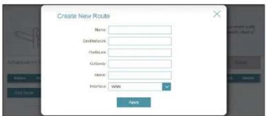
IPv6
To configure IPv6 rules, on the Static Routes page click IPv6. To return to the main IPv4 static routes page, click IPv4.
If you wish to remove a rule, click on its trash can icon in the Delete column. If you wish to edit a rule, click on its pencil icon in the Edit column. If you wish to create a new rule, click the Add Rules button. Click Save when you are done. If you edit or create a rule, the following options will appear:
Name: Enter a name for the rule.
DestNetwork: This is the IP address of the router used to reach the specified destination.
PrefixLen: Enter the IPv6 address prefix length of the packets that will take this route.
Gateway: Enter your next hop gateway to be taken if this route is used.
Metric: Enter a route metric value ranging from 0 to 15. This value indicates the cost of using this route.
Interface: Select the interface that the IP packet must use to transit out of the router when this route is used.
Click Apply when you are done.

Dynamic DNS
Most Internet Service Providers (ISPs) assign dynamic (changing) IP addresses. Using a dynamic DNS service provider, people can enter your domain name in their web browser to connect to your server no matter what your IP address is.
In the Features menu on the bar on the top of the page, click Dynamic DNS.
Enable Dynamic Enable or disable dynamic DNS. Enabling this feature will reveal DNS: further configuration options.
Status: Displays the current dynamic DNS connection status.
Server Address: Select a dynamic DNS server from the drop-down menu, or select Manual to enter the address of your dynamic DNS server.
Host Name: Enter the host name that you registered with your dynamic DNS service provider.
User Name: Enter your dynamic DNS username.
Password: Enter your dynamic DNS password.
Time Out: Enter a time out time (in hours).
Click Save when you are done.
At the bottom of the page are the IPv6 host settings. To configure an IPv6 dynamic DNS host, refer to IPv6 Host on page 84.

IPv6 Host
The IPv6 host settings are found at the bottom of the Dynamic DNS page.
If you wish to remove a rule, click on its trash can icon in the Delete column. If you wish to edit a rule, click on its pencil icon in the Edit column. If you wish to create a new rule, click the Add Record button. Click Save when you are done. If you edit or create a rule, the following options will appear:
Host Name: Enter the host name that you registered with your dynamic DNS service provider.
IPv6 Address: Enter the IPv6 address of the dynamic DNS server. Alternatively, select the server device in the drop-down menu.
Click Save when you are done.

Quick VPN
This page will help you configure the Quick VPN feature of your router. For more information refer to Quick VPN on page 99. Before proceeding, ensure that your Internet connection is working properly. We recommend configuring Dynamic DNS before proceeding with Quick VPN setup. If your router's IP address is assigned by your ISP using DHCP, it may frequently change, requiring clients to be reconfigured. Using a dynamic DNS service provides a URL that automatically redirects you to the correct IP address. In the Features menu on the bar on the top of the page, click Quick VPN.
Configure the following options:
L2TP over IPsec: Enable or disable the Quick VPN server.
If Quick VPN is enabled, the following options are available:
Username: Enter a username between 1 and 20 characters.
Password: Enter a username between 1 and 20 characters.
PSK: Enter a passkey between 6 and 64 characters.
Save Click this button to save the current Quick VPN settings to your local hard drive. Configuration To Local Hard Drive: For Apple iOS devices and OS X: From a computer browser click this button to export a profile to simplify setup. E-mail this file as an attachment to your Apple mobile device or open the file in OS X.

Quick VPN (continued)
Advanced Settings - Address Autoconfiguration Settings
Authentication Choose the authentication protocol type: MSCHAPv2, PAP, or CHAP. Protocol: MSCHAPv2 is the default.
MPPE: Select the encryption cipher strength: None, RC4-40, or RC4-128. RC4-128 is the default.
Click Save when you are done.

Management Time & Schedule Time
The Time page allows you to configure, update, and maintain the correct time on the internal system clock. From here you can set the time zone, the Network Time Protocol (NTP) server, and enable or disable daylight saving time.
In the Management menu on the bar on the top of the page, click Time & Schedule.
Time Configuration
Time Zone: Select your time zone from the drop-down menu.
Time: Displays the current date and time of the router.
Enable Daylight Saving: Enable or disable daylight saving time.
Automatic Time Configuration
Update Time Using an NTP Server:
Enable or disable to allow an NTP server on the Internet to synchronize the time and date with your router. If you enable this option, select an NTP server from the drop-down menu. To configure the router's time and date manually, disable this option and use the drop-down menus that appear to input the time and date.
Click Save when you are done.


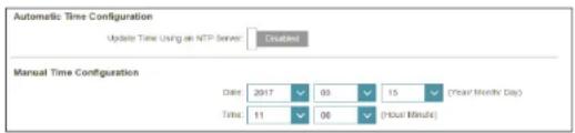
Schedule
Some router functions can be controlled through a pre-configured schedule. To create, edit, or delete schedules, from the Time page click Schedule. To return to the Time page, click Time.
If you wish to remove a rule, click on its trash can icon in the Delete column. If you wish to edit a rule, click on its pencil icon in the Edit column. If you wish to create a new rule, click the Add Rule button. Click Save when you are done. If you edit or create a rule, the following screen will appear:

First, enter the name of your schedule in the Name field.
Each box represents one hour, with the time at the top of each column. To add a time period to the schedule, simply click on the starting hour and drag to the ending hour. You can add multiple days to the schedule, but only one period per day.
To remove a time period from the schedule, click on the cross icon.
Click Save when you are done.
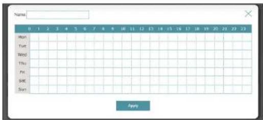

bar
| Day | Value | |---|---| | Mon | 5.00 - 10.00 | | Tue | 5.00 - 10.00 | | Wed | 2.00 - 14.00 | | Thu | | | Fri | 11.00 - 21.00 | | Sat | | | Sun | |System Log
The router keeps a running log of events. This log can be sent to a Syslog server, or sent to your email address. In the Management menu on the bar on the top of the page, click System Log.
SysLog Settings
Enable Logging to Check this box to send the router logs to a SysLog Server. Syslog Server:
If Logging to the Syslog Server is Enabled:
Syslog Server IP Enter the IP address for the Syslog server. If the Syslog server is connected to the extender, select it from the drop-down menu to automatically populate the field.
Email Settings
Enable E-mail Enable this option if you want the logs to be automatically sent to Notification: an email address.
If E-mail notification is Enabled:
From E-mail Enter the email address your SysLog messages will be sent from. Address:
To E-mail Address: Enter the email address your SysLog messages will be sent to.
SMTP Server Enter your SMTP server address. Address:
SMTP Server Port: Enter your SMTP server port.
Enable Check this box if your SMTP server requires authentication. Authentication:

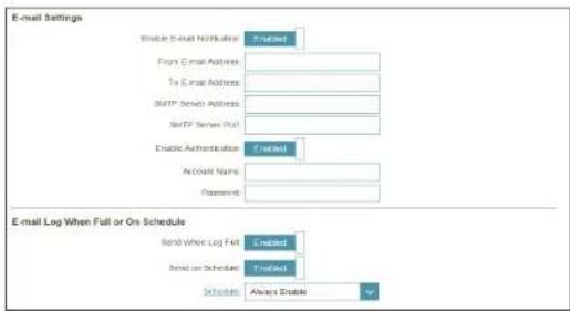
System Log (continued)
Account Name: Enter your SMTP account name.
Password: Enter your SMTP account's password.
E-mail Log When Full or On Schedule
Send When Log If enabled, this option will set the router to send the log when it is full. Full:
Send on Schedule: If enabled, this option will set the router to send according to a set schedule.
Schedule: If you enable Send On Schedule, use the drop-down menu to select a schedule to apply. The schedule may be set to Always Enable, or you can create your own schedules in the Schedules section. Refer to Schedule on page 88 for more information.
Click Save when you are done.

System Admin
This page will allow you to change the administrator (Admin) password and enable remote management. In the Management menu on the bar on the top of the page, click System Admin. To load, save, reset settings, or reboot the router, click System and refer to Schedule on page 88.
Admin Password
Password: Enter a new password for the administrator account. You will need to enter this password whenever you configure the router using a web browser.
Enable Graphical Authentication (CAPTCHA):
Enables a challenge-response test to require users to type letters or numbers from a distorted image displayed on the screen to prevent online hackers and unauthorized users from gaining access to your router's network settings.
Advanced Settings - Administration
Enable HTTPS Server:
Check to enable HTTPS to connect to the router securely. Instead of using http://dlinkrouter.local/, you must use https://dlinkrouter.local./ in order to connect to the router.
Enable Remote Management:
Remote management allows the COVR-2600R to be configured from the Internet by a web browser. A password is still required to access the web management interface.
Remote Admin Port:
The port number used to access the COVR-2600R is used in the URL. Example: http://x.x.x.x:8080 where x.x.x.x is the Internet IP address of the COVR-2600R and 8080 is the port used for the web management interface. Note: If you enabled Use HTTPS and wish to access the router remotely and securely, you must enter https:// at the beginning of the address.
Click Save when you are done.
![D-Link D-Link (OR: 0001) [NT: 0001] Home | Settings | Features | Management Admin The admin account can change all reader settings. To keep your user account, you should give the admin account a linking password. Management => Admin System Save Admin Password Password: Access Enable Original Authentication (CAPTCHA) Enabled Advanced Settings... Administration Enable HTTPS Server Enabled Enable Remote Management Enabled Remote Admin Port: 8361 Use HTTPS Established](/content/2026/05/994801/images/73e07138641f3d3a262b8099731708f86f38ec427476b00615b14a15b08aa6d3.jpg)
System
This page allows you to save the router's current configuration, load a previously saved configuration, reset the router to its factory default settings, or reboot the router.
From the Admin page, click System. To return to the Admin page, click Admin.
System
Save Settings To Local Hard Drive: This option will save the current router configuration settings to a file on your computer.
Load Settings This option will load a previously saved router configuration file. This will overwrite the router's current configuration. From Local Hard Drive:
Restore To Factory Default Settings: This option will restore all configuration settings back to the settings that were in effect at the time the router was shipped from the factory. Any settings that have not been saved will be lost, including any rules that you have created. If you want to save the current router configuration settings, use the Save Settings To Local Hard Drive button above.
Auto Reboot Configuration
Reboot The Device: Click the Reboot button to reboot the router immediately.
Auto Reboot: You may set the COVR-2600R to automatically reboot at a set time. The options are Never, Daily, Weekly. You may set the hour using a 24 hour format, the minute, and the day you wish to have the COVR-2600R automatically reboot.
Click Save when you are done.
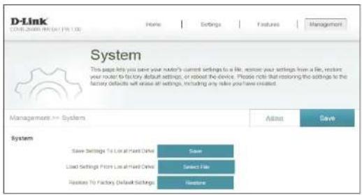


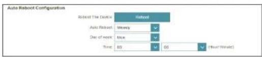
Upgrade
This page will allow you to upgrade the router's firmware, either automatically or manually. To manually upgrade the firmware, you must first download the file from http://support.dlink.com.
In the Management menu on the bar on the top of the page, click Upgrade.
Firmware Information
Current Firmware Version/Date : The current firmware's version and date will be displayed.
Check for New Firmware: Click this button to prompt the router to automatically check for a new firmware version. If a newer version is found, it will prompt you to install it.
Upgrade Manually
Upgrade If you wish to upgrade manually, first download the firmware file you wish to upgrade to. Next, click the Select File button and browse to the firmware file you want to install. With the file selected, click Upload to begin the upgrade process.


Statistics
On the Statistics page you can view the amount of packets that pass through the router on the WAN, LAN, and wireless segments.
In the Management menu on the bar on the top of the page, click Statistics.
You can view the Internet, LAN, Wi-Fi 2.4 GHz, or Wi-Fi 5 GHz by clicking on the respective tabs at the top. The graph will update in real time. To clear the information on the graph, click Clear.
The traffic counter will reset if the device is rebooted.

line
| Metric | Value | | -------------- | --------- | | Total Packets | 556746 | | Total KBytes | 78068 | | KBytes | 0 | | Received | 2896630 |Configuration - COVR-1300E
To access the COVR-1300E configuration utility, either open a web-browser such as Internet Explorer and enter http://dlinkap.local./ in the address bar, or click Go to settings in the client box in the Extenders overview window on the COVR-2600R web interface home page.

Enter your password. This password is the same password used for accessing the COVR-2600R configuration utility. If you previously followed the setup wizard, please use the admin password you entered during the wizard. Otherwise, leave the password blank. Click Log In to proceed.
Note: If you cannot remember your password and cannot log in, press the reset/wps button on the back of the device for longer than 10 seconds to restore the router to its default settings.
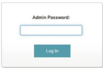
System
This page allows you to reset the extender to its factory default settings, or reboot the extender. This is the default page when accessing the COVR-1300E's configuration utility.
In the Management menu on the bar on the top of the page, click System.
System
Restore To Factory Default Settings:
This option will restore all configuration settings back to the settings that were in effect at the time the router was shipped from the factory. Any settings that have not been saved will be lost, including any rules that you have created.
Reboot The Device: Click the Reboot button to reboot the router immediately.

Upgrade
This page will allow you to upgrade the extender's firmware, either automatically or manually. To manually upgrade the firmware, you must first download the relevant file from http://support.dlink.com.
In the Management menu on the bar on the top of the page, click Upgrade.
Firmware Information
Current Firmware The current firmware's version and date will be displayed. Version/Date :
Check for New Firmware: Click this button to prompt the router to automatically check for a new firmware version. If a newer version is found, it will prompt you to install it.
Upgrade Manually
Upgrade If you wish to upgrade manually, first download the firmware file you wish to upgrade to. Next, click the Select File button and browse to the firmware file you want to install. With the file selected, click Upload to begin the upgrade process.


flowchart
graph LR
    A["Upgrade Manually"] --> B["Upgrade Warehouse"]
    B --> C["Sales File"]
    B --> D["Upload"]
    C --> E["GOVR-000R_PWNTMIDTSB"]
Statistics
On the Statistics page you can view the amount of packets that pass through the extender LAN, and wireless segments.
In the Management menu on the bar on the top of the page, click Statistics.
You can view the LAN, 2.4 GHz Wi-Fi, 5 GHz Wi-Fi, 2.4 GHz Extender Wi-Fi, and 5 GHz Extender Wi-Fi by clicking on the respective tabs at the top. The graph will update in real time. To clear the information on the graph, click Clear.
The traffic counter will reset if the device is rebooted.

line
| Segment | Total Packets | Total KBytes(c) | KBytes/sec | |---------|---------------|-----------------|-------------| | Link | 1214 | 1163 | 4 | | 2000s MWh | 8645 | 134 | 1 |Quick VPN
This router is equipped with D-Link's Quick VPN technology. Virtual Private Networking (VPN) creates a connection between devices across the Internet. Using Quick VPN allows you to securely connect your computer or mobile device to places with free, untrusted Wi-Fi hotspots in places like coffee shops and hotels by encrypting and relaying it through your home Internet connection. This extra 'hop' reduces the chances of hackers stealing your information, such as logins, passwords, and credit card numbers. When traveling, Quick VPN lets you watch sports and use video streaming services without experiencing blackouts or filtering. You can surf the whole Internet unfiltered and unblocked, just as you would at home.

flowchart
graph LR
    A["Without Quick VPN"] --> B["Stealing Data"]
    B --> C["Public Unsecured Wi-Fi Hotspot"]
    C --> D["InternetYour Laptop Potential Hacker"]
    E["With Quick VPN"] --> F["Your Laptop"]
    F --> G["Wi-Fi Hotspot"]
    G --> H["Internet Public Unsecured Wi-Fi Hotspot"]
    H --> I["You are Network with Quick VPN Server"]
    style A fill:#f9f,stroke:#333
    style E fill:#f9f,stroke:#333
    style F fill:#f9f,stroke:#333
    style G fill:#ccf,stroke:#333
    style H fill:#ccf,stroke:#333
    style I fill:#ccf,stroke:#333
Important Information
The following instructions explain and help you to configure your D-Link Quick VPN enabled router and devices to create a Virtual Private Network (VPN). This feature is provided for advanced users who wish to connect remotely and use their router's Internet connection to add a layer of security while using untrusted networks. Configure the Quick VPN Server on your router first, then set up client devices to connect through your router's WAN connection.
- Quick VPN only provides an added layer of security against specific types of snooping attacks and does not guarantee complete data integrity or protection. Only traffic in the tunnel between your router and device will be encrypted, WAN traffic will leave your D-Link Quick VPN-enabled router unencrypted.
- Keep your Quick VPN Username, Password, and Passkey safe. It is recommended that you change these credentials periodically.
- A device connected via Quick VPN tunnel may experience lower data throughput and higher latency due to a number of factors including: Internet conditions, local and remote network Wi-Fi and WAN bandwidth limitations, and increased latency. This may negatively impact real-time voice and video communication.
- Quick VPN supports up to five concurrent VPN client sessions using the same login and password. Quick VPN uses L2TP/IPsec with MS-CHAPv2, PAP, or CHAP authentication.
- You device may warn you that your information may be intercepted, but since you control the Quick VPN server, you may ignore this.
- UDP Ports 500, 4500, 1701 and IP Port 50 must be open in order for Quick VPN to work.
- L2TP/IPsec VPN usage may be restricted in some countries and on some networks. If you have trouble using Quick VPN on some networks, and are not violating network access rules, try contacting your ISP or network administrator.
- Devices connected via Quick VPN are assigned addresses on a separate subnet (ex. 192.168.1.x). Some network resources may be unavailable when connecting via Quick VPN.
- If your Internet connection uses DHCP, it is strongly recommended that you first set up Dynamic DNS (DDNS), such as D-Link DDNS, to eliminate the need to reconfigure client devices in the event your ISP assigns you a new WAN IP address.
Quick VPN Server Setup Instructions
Configure the following options:
L2TP over IPsec: Enable or disable the Quick VPN server.
If L2TP over IPsec is enabled, the following options are available:
Username: Enter a username between 1 and 20 characters.
Password: Enter a username between 1 and 20 characters.
PSK: Enter a passkey between 6 and 64 characters.
Save Click this button to save the current Quick VPN settings to your local Configuration To hard drive. Local Hard Drive: For Apple iOS devices and OS X: From a computer browser click this button to export a profile to simplify setup. E-mail this file as an attachment to your Apple mobile device or open the file in OS X.


Advanced Settings - Address Autoconfiguration Settings
Authentication Choose the authentication protocol type: MSCHAPv2, PAP, or CHAP. Protocol: MSCHAPv2 is the default.
MPPE: Select the encryption cipher strength: None, RC4-40, or RC4-128. RC4-128 is the default.
Click Save when you are done.
When you are done configuring VPN settings, refer to the following sections for more information on how to set up VPN clients.
iOS Devices VPN Setup Instructions
This section provides Quick VPN setup instructions for iOS devices using the Export Profile function. Refer to Quick VPN Server Setup Instructions on page 101 for more information.
Open the e-mail containing your Quick VPN profile.

Open the attachment.

VPN Setup Instructions (Continued)
The Install Profile dialog will appear, tap Install in the upper right-hand corner of your screen.
| Cancel | Warning | Install |
| VPN | ||
| The network traffic of your iPad may be secured, filtered, or monitored by a VPN server. | ||
| UNSIGNED PROFILE | ||
| The profile is not signed. | ||
Enter your device's passcode when prompted.
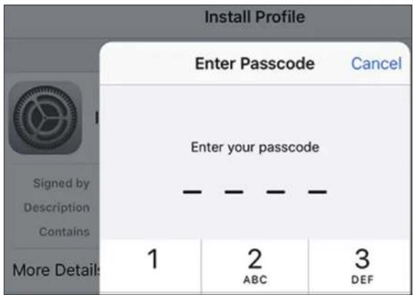
VPN Setup Instructions (Continued)
Acknowledge the disclaimer by tapping Install in the upper right-hand corner. Tap the red Install button.
Enter the Shared Secret (PSK) from the Quick VPN configuration page. Tap Done.
Your iOS device is now configured to connect to your Quick VPN server.
| Install Profile | |
| Cancel | Install |
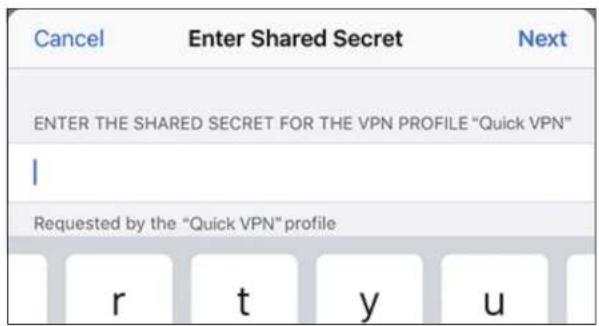

Connect or Disconnect
To connect to or disconnect from your Quick VPN server, open Settings and tap the button next to VPN.
The VPN icon will appear in the notification area at the top of your screen indicating that your device is currently connected to the Quick VPN server.

Mac OS X VPN Setup Instructions
This section provides Quick VPN setup instructions for OS X using the Export Profile function. Refer to Quick VPN Server Setup Instructions on page 101 for more information.
Open the exported profile. The Install Profile dialog will appear; click Continue and Install.
Enter your user account password when prompted. Close the Profiles dialog.

Go to 📄 > System Preferences... > Network and select the Quick VPN connection and click Authentication Settings.

VPN Setup Instructions (Continued)
Enter your Passkey in the Shared Secret text box and click OK, Apply, then OK.
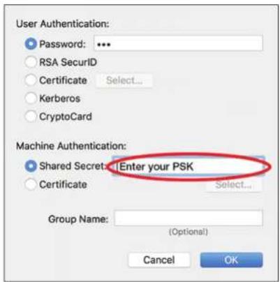
Your Mac is now configured to connect to your Quick VPN server.
Connect or Disconnect
To connect to or disconnect from your Quick VPN server, go to 📄> System Preferences... > Network.
Select the Quick VPN connection and click on the Connect or Disconnect button.


Windows 7 VPN Setup Instructions
Click the Start button and type vpn into the Search programs and files box.
Select Set up a virtual private network (VPN) connection.

Enter the IP/DDNS address of your Quick VPN server in the Internet address box, create a name for your connection in the Destination Name, check Don't Connect now; just set it up so I can connect later, and click Next.
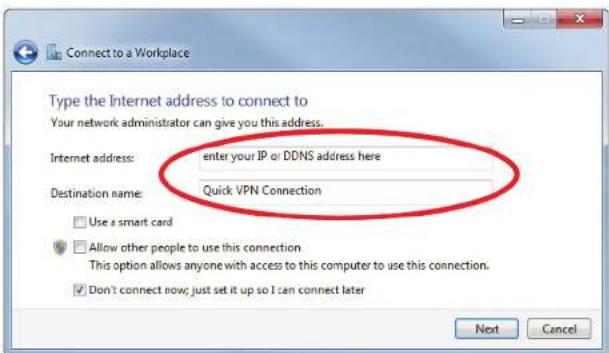
VPN Setup Instructions (Continued)
Enter your Username. If you would like windows to save your password, enter your Password and check Remember this password. Click Create to continue.
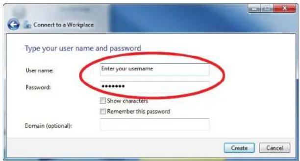
Do not click Connect Now.
Click Close. Click the Start button and type view network connections into the Search programs and files text box. Select View network connections.

VPN Setup Instructions (Continued)
Click Advanced settings. Enter your Passkey in the Key text box under Use preshared key for authentication. Click OK to close Advanced Properties and click OK to close Quick VPN Connection Properties.

Your Windows 7 system is now configured to connect to your Quick VPN server.
Connect or Disconnect
To connect to or disconnect from your Quick VPN server, click on the Network Settings icon in the notification area of the Windows taskbar and from the Dial Up and VPN section click on your Quick VPN connection and click on the Connect or Disconnect button.
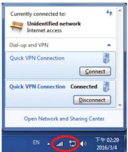
Windows 8.1/8 VPN Setup Instructions
This section provides Quick VPN setup instructions for Windows 8.1/8.
Click the Start button and type vpn.
Select Manage virtual private networks.
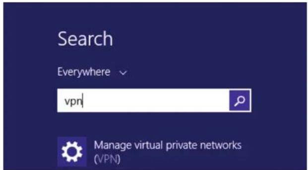
From the Network Settings page, click Add a VPN Connection.

Add a VPN Connection
1 Select Microsoft from VPN Provider.
2 Create a name for your VPN connection.
3 Enter your IP/DDNS address of your Quick VPN server.
4 Select User name and password from Type of sign-in info.
5 If you would like windows to remember your sign-in information, enter your User name, Password, and select Remember my sign-in info
6 Choose Save.

VPN Setup Instructions (Continued)
Right-click on the Quick VPN Connection you just created and left-click on Properties.
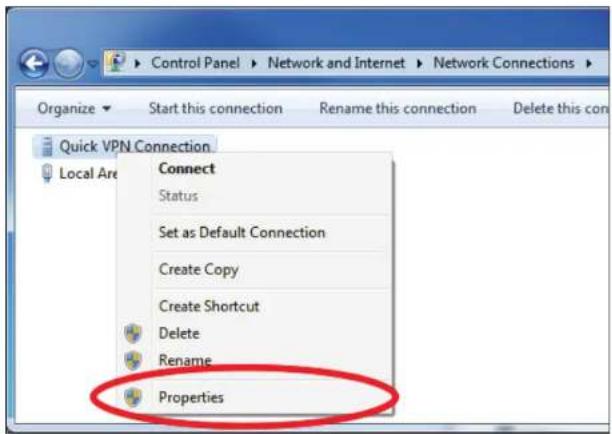
Select the Security tab. For the Type of VPN, select Layer 2 Tunneling with IPsec (L2TP/IPSec).

VPN Setup Instructions (Continued)
Click the Start button and type view network connections.
Select View network connections.

Right-click your Quick VPN Connection and left-click Properties. Select the Security tab.
For the Type of VPN, select Layer 2 Tunneling with IPsec (L2TP/IPSec).

VPN Setup Instructions (Continued)
Click Advanced settings. Enter your Passkey in the Key text box under Use preshared key for authentication.
Click OK to close Advanced Properties and click OK to close Quick VPN Properties.

Your Windows 8.1/8 system is now configured to connect to your Quick VPN server.
Connect or Disconnect
To connect to or disconnect from your Quick VPN server, click on the Network Settings icon in the notification area of the Windows taskbar. Click on your Quick VPN connection and click on the Connect or Disconnect button.


Windows 10 VPN Setup Instructions
This section provides Quick VPN setup instructions for Windows 10.
Click Start > Settings > Network & Internet > Network and Sharing Center > VPN > Add a VPN Connection.

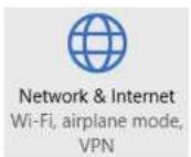

Add a VPN Connection
1 Select Windows (built-in) from the VPN Provider drop down menu.
2 Create a name for your VPN connection.
3 Enter your IP/DDNS address of your Quick VPN server.
4 Select L2TP/IPSec with pre-shared key from VPN type.
5 Enter the Passkey.
6 Select User name and password from Type of sign-in info.
If you would like windows to remember your sign-in information, enter your User name, Password, and select Remember my sign-in info
7 Choose Save.
Your Windows 10 system is now configured to connect to your Quick VPN server.

Connect or Disconnect
To connect to or disconnect from your Quick VPN server, click on the Network Settings icon in the notification area of the Windows taskbar and click on your Quick VPN connection.

The Network & Internet Settings page will open. Click on the Connect or Disconnect button.

Android VPN Setup Instructions
This section provides Quick VPN setup instructions for Android devices. Your device's screens may vary.
Go to Settings > More from the Wireless & networks > VPN > +


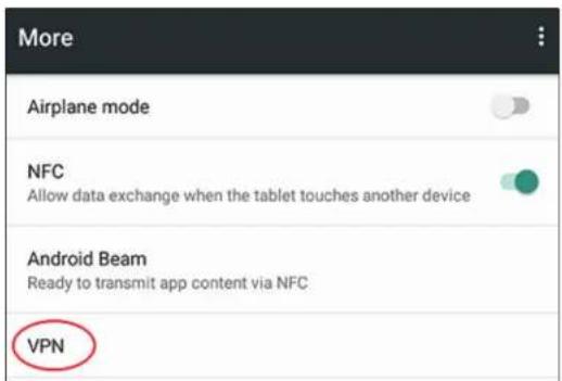

Edit VPN Profile
1 Enter a name for your VPN connection.
2 Select L2TP/IPSec PSK for Type.
3 Enter the IP/DDNS address of your Quick VPN server.
4 Enter your Passkey in IPSec pre-shared key field.
5 Choose Save.
Your Android device is now configured to connect to your Quick VPN server.

Connect or Disconnect
To connect to or disconnect from your Quick VPN server, go to Settings > More from the Wireless & networks > VPN and select the Quick VPN connection you created.

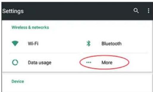


Connect or Disconnect (Continued)
To connect, enter your Username and Password and select CONNECT.

To disconnect, select DISCONNECT.
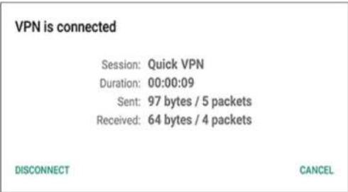
Connect a Wireless Client to your Router WPS Button
The easiest and most secure way to connect your wireless devices to the router is with WPS (Wi-Fi Protected Setup). Most wireless devices such as wireless adapters, media players, Blu-ray DVD players, wireless printers and cameras will have a WPS button (or a software utility with WPS) that you can press to connect to the COVR-2600R router. Please refer to your user manual for the wireless device you want to connect to make sure you understand how to enable WPS. After your device's manual, follow the steps below:
Step 1 - Press the WPS button on the COVR-2600R for about 1 second. The LED on the front will start to blink.

Step 2 - Within 2 minutes, press the WPS button on your wireless device (or launch the software utility and start the WPS process).
Step 3 - Allow up to 1 minute for your connection to be configured. Once the Internet light stops blinking, you will be connected and your wireless connection will be encrypted with WPA2.
Wireless Basics
D-Link wireless products are based on industry standards to provide easy-to-use and compatible high-speed wireless connectivity within your home, business, or public access wireless networks. Strictly adhering to the IEEE standard, the D-Link wireless family of products will allow you to securely access the data you want, when, and where you want it. You will be able to enjoy the freedom that wireless networking delivers.
A wireless local area network (WLAN) is a cellular computer network that transmits and receives data with radio signals instead of wires. Wireless LANs are used increasingly in both home and office environments, and public areas such as airports, coffee shops and universities. Innovative ways to utilize WLAN technology are helping people work, and communicate more efficiently. Increased mobility and the absence of cabling and other fixed infrastructure have proven to be beneficial for many users.
Wireless users can use the same applications they use on a wired network. Wireless adapter cards used on laptop and desktop systems support the same protocols as Ethernet adapter cards.
Under many circumstances, it may be desirable for mobile network devices to link to a conventional Ethernet LAN in order to use servers, printers or an Internet connection supplied through the wired LAN. A wireless router is a device used to provide this link.
What is Wireless?
Wireless or Wi-Fi technology is another way of connecting your computer to the network without using wires. Wi-Fi uses radio frequency to connect wirelessly so you have the freedom to connect computers anywhere in your home or office network.
Why D-Link Wireless?
D-Link is the worldwide leader and award winning designer, developer, and manufacturer of networking products. D-Link delivers the performance you need at a price you can afford. D-Link has all the products you need to build your network.
How does wireless work?
Wireless works similarly to how cordless phones work, through radio signals that transmit data from one point A to point B. But wireless technology has restrictions as to how you can access the network. You must be within the wireless network range area to be able to connect your computer. There are two different types of wireless networks: Wireless Local Area Network (WLAN), and Wireless Personal Area Network (WPAN).
Wireless Local Area Network (WLAN)
In a wireless local area network, a device called an Access Point (AP) connects computers to the network. The access point has a small antenna attached to it, which allows it to transmit data back and forth over radio signals. With an indoor access point the signal can travel up to 300 feet. With an outdoor access point the signal can reach out up to 30 miles to serve places like manufacturing plants, industrial locations, university and high school campuses, airports, golf courses, and many other outdoor venues.
Wireless Personal Area Network (WPAN)
Bluetooth is the industry standard wireless technology used for WPAN. Bluetooth devices in WPAN operate in a range up to 30 feet away.
Compared to WLAN the speed and wireless operation range are both less than WLAN, but in return it doesn't use nearly as much power. This makes it ideal for personal devices, such as mobile phones, PDAs, headphones, laptops, speakers, and other devices that operate on batteries.
Who uses wireless?
Wireless technology as become so popular in recent years that almost everyone is using it, whether it's for home, office, business, D-Link has a wireless solution for it.
Home Uses/Benefits
• Gives everyone at home broadband access
- Surf the web, check email, instant message, etc.
- Gets rid of the cables around the house
- Simple and easy to use
Small Office and Home Office Uses/Benefits
- Stay on top of everything at home as you would at office
- Remotely access your office network from home
- Share Internet connection and printer with multiple computers
- No need to dedicate office space
Where is wireless used?
Wireless technology is expanding everywhere, not just at home or office. People like the freedom of mobility and it's becoming so popular that more and more public facilities now provide wireless access to attract people. The wireless connection in public places is usually called "hotspots".
Using a D-Link USB adapter with your laptop, you can access the hotspot to connect to the Internet from remote locations like: airports, hotels, coffee shops, libraries, restaurants, and convention centers.
Wireless network is easy to setup, but if you're installing it for the first time it could be quite a task not knowing where to start. That's why we've put together a few setup steps and tips to help you through the process of setting up a wireless network.
Tips
Here are a few things to keep in mind, when you install a wireless network.
Centralize your router or access point
Make sure you place the router/access point in a centralized location within your network for the best performance. Try to place the router/access point as high as possible in the room, so the signal gets dispersed throughout your home. If you have a two-story home, you may need a repeater to boost the signal to extend the range.
Eliminate Interference
Place home appliances such as cordless telephones, microwaves, and televisions as far away as possible from the router/access point. This would significantly reduce any interference that the appliances might cause since they operate on same frequency.
Security
Don't let your next-door neighbors or intruders connect to your wireless network. Secure your wireless network by turning on the WPA or WEP security feature on the router. Refer to the product manual for detail information on how to set it up.
Technical Specifications
| Technical Specifications - COVR-2600R AC2600 Wi-Fi Router | ||
| General | ||
| Device Interfaces • IEEE 802.11 ac/n/g/b/a wireless LAN | • 10/100/1000 Gigabit Ethernet WAN port• Four 10/100/1000 Gigabit Ethernet LAN ports• USB 3.0 port | • Power button• Wireless On/Off button• WPS Button• Pin-sized reset button• Power connector |
| LEDs • Power | • Internet• 2.4 GHz Wi-Fi band | • 5 GHz Wi-Fi band• USB |
| Antenna Type • Four external antennas | ||
| Data Signal Rate • 2.4 GHz | • Up to 800 Mbps ^1 | • 5 GHz• Up to 1733 Mbps ^1 |
| Standards • IEEE 802.11ac | • IEEE 802.11n• IEEE 802.11g• IEEE 802.11b• IEEE 802.11a | • IEEE 802.3ab• IEEE 802.3u• Auto Negotiation• Auto MDI/MDIX |
| Minimum Requirements • Windows 10/8.1/8/7 or MAC OS X 10.6 or higher• Internet Explorer 10, Firefox 28.0, Chrome 28.0, Safari 6.0, or later | • Network Interface Card• Cable/DSL modem or other Internet Service Provider equipment with Ethernet port | |
| Functionality | ||
| Security | • WPA & WPA2 (Wi-Fi Protected Access) | • WPS (Wi-Fi Protected Setup) |
| Advanced Features • Web setup wizard | • Quality of Service (QoS)• Demilitarized Zone (DMZ)• Air Time Fairness (ATF)• Seamless Roaming (multiple AP steering)• Adaptive Path Selection (APS) | • Firewall - Network Address Translation (NAT)• Wi-Fi Multimedia (WMM)• MU-MIMO• Smart Band Steering (Smart Connect)• AP Steering load balancing |
Appendix B - Technical Specifications
| Physical | ||
| Dimensions • 287.21 x 205.86 x 52.62 mm (10.95 x 8.10 x 2.07 in) | ||
| Weight • 826 g (1.82 lbs) | ||
| Power Adapter | • Input: 100 to 240 V AC, 50/60 Hz | • Output: 12 V, 3 A |
| Temperature | • Operating: 0 to 40 °C (32 to 104 °F) | • Non-Operating: -20 to 65 °C (-4 to 149 °F) |
| Humidity | • Operating: 10% to 90% non-condensing | • Non-Operating: 5% to 95% non-condensing |
| Certifications • FCC | • IC• CE ^2 | • CSA• WI-FI Certified |
| Technical Specifications - COVR-1300E AC1300 Wi-Fi Range Extender | ||
| General | ||
| Device Interfaces • IEEE 802.11 ac/n/g/b/a wireless LAN | • Two 10/100/1000 Gigabit Ethernet LAN ports• Power button• WPS button | • Wireless On/Off button• Pin-sized reset button• Power connector |
| LEDs | • Power• 2.4 GHz band uplink strength• 5 GHz band uplink strength | • 5 GHz band downlink strength• 2.4 GHz band downlink strength |
| Antenna Type | • Two internal antennas | |
| Data Signal Rate | • 2.4 GHz• Up to 400 Mbps ^1 | • 5 GHz• Up to 866 Mbps ^1 |
| Standards | • IEEE 802.11ac• IEEE 802.11n• IEEE 802.11g• IEEE 802.11b• IEEE 802.11a | • IEEE 802.3ab• IEEE 802.3u• Auto Negotiation• Auto MDI/MDIX |
| Minimum Requirements | • Windows 10/8.1/8/7 or MAC OS X 10.6 or higher• Internet Explorer 10, Firefox 28.0, Chrome 28.0, Safari 6.0, or later | • COVR-2600R Covr System or existing wireless network• Network Interface Card |
| Functionality | ||
| Security | • WPA & WPA2 (Wi-Fi Protected Access) | • WPS (Wi-Fi Protected Setup) |
| Advanced Features | • Wi-Fi Multimedia (WMM) | |
| Physical | ||
| Dimensions • 134 x 134 x 32.6 mm (5.28 x 5.28 x 1.28 in) | ||
| Weight • 322 g (0.71 lbs) | ||
| Power Adapter | • Input: 100 to 240 V AC, 50/60 Hz | • Output: 12 V, 1 A |
| Temperature | • Operating: 0 to 40 °C (32 to 104 °F) | • Non-operating: -20 to 65 °C (-4 to 149 °F) |
| Humidity | • Operating: 10% to 90% non-condensing | • Non-operating: 5% to 95% non-condensing |
| Certifications • FCC | • IC• CE2 | • CSA• Wi-Fi Certified |
Regulatory Statements - COVR-2600R
Federal Communication Commission Interference Statement
This equipment has been tested and found to comply with the limits for a Class B digital device, pursuant to Part 15 of the FCC Rules. These limits are designed to provide reasonable protection against harmful interference in a residential installation. This equipment generates, uses and can radiate radio frequency energy and, if not installed and used in accordance with the instructions, may cause harmful interference to radio communications. However, there is no guarantee that interference will not occur in a particular installation. If this equipment does cause harmful interference to radio or television reception, which can be determined by turning the equipment off and on, the user is encouraged to try to correct the interference by one of the following measures:
- Reorient or relocate the receiving antenna.
- Increase the separation between the equipment and receiver.
- Connect the equipment into an outlet on a circuit different from that to which the receiver is connected.
- Consult the dealer or an experienced radio/TV technician for help.
Non-modifications Statement:
Any changes or modifications not expressly approved by the party responsible for compliance could void the user's authority to operate this equipment.
Caution:
This device complies with Part 15 of the FCC Rules. Operation is subject to the following two conditions:
(1) This device may not cause harmful interference, and (2) this device must accept any interference received, including interference that may cause undesired operation.
This device and its antenna(s) must not be co-located or operating in conjunction with any other antenna or transmitter except in accordance with FCC multi-transmitter product procedures. For product available in the USA/Canada market, only channel 1\~11 can be operated. Selection of other channels is not possible.
Note
The country code selection is for non-USA models only and is not available to all USA models. Per FCC regulations, all WiFi product marketed in the USA must be fixed to USA operational channels only.
RF Frequency Requirements
This device is for indoor use only when using all channels in the 5.150 GHz to 5.250 GHz frequency range. High power radars are allocated as primary users of the 5.725 GHz to 5.850 GHz bands. These radar stations can cause interference with and/or damage this device.
It is restricted to indoor environments only.
IMPORTANT NOTICE:
FCC Radiation Exposure Statement
This equipment complies with FCC radiation exposure limits set forth for an uncontrolled environment. This equipment should be installed and operated with minimum distance 29 cm between the radiator and your body.
Innovation, Science and Economic Development Canada (ISED) Statement:
This Class B digital apparatus complies with Canadian ICES-003.
Innovation, Science and Economic Development Canada (ISED) Statement:
This device complies with ISED licence-exempt RSS standard(s). Operation is subject to the following two conditions:
(1) this device may not cause interference, and
(2) this device must accept any interference, including interference that may cause undesired operation of the device.
For transmitters equipped with detachable antennas. This radio transmitter (IC: 4216A-IR883A1) has been approved by Industry Canada to operate with the antenna types listed below with the maximum permissible gain and required antenna impedance for each antenna type indicated. Antenna types not included in this list, having a gain greater than the maximum gain indicated for that type, are strictly prohibited for use with this device.
| Type Manufacture | Gain | Connector | |
| Dipole RF Link 2.4G: 2dBi/5G: 3dBi RSMA | |||
Radiation Exposure Statement
This equipment complies with ISED radiation exposure limits set forth for an uncontrolled environment. This equipment should be installed and operated with minimum distance 34 cm between the radiator and your body.
This unit is to be used with a power supply, Model WA-36A12R.
Avertissement
European Community Declaration of Conformity:
| Česky [Czech] | Tímto D-Link Corporation prohlašuje, že tento produkt, jeho příslušenství a software jsou v souladu se směrnici 2014/53/EU. Celý text ES prohlášení o shodě vydaného EU a o firmwaru produktu lze stáhnout na stránkách k produktu www.dlink.com. |
| Dansk [Danish] | D-Link Corporation erklærer herved, at dette produkt, tilbehør og software er i overensstemmelse med direktiv 2014/53/EU. Den fulde tekst i EU-overensstemmelseserklæringen og produktfirmware kan wnloades fra produktsiden hos www.dlink.com. |
| Deutsch [German] | Hiermit erklärt die D-Link Corporation, dass dieses Produkt, das Zubehör und die Software der Richtlinie 2014/53/EU entsprechen. Der vollständige Text der Konformitätserklärung der Europäischen Gemeinschaft sowie die Firmware zum Produkt stehen Ihnen zum Herunterladen von der Produktseite im Internet auf www.dlink.com zur Verfügung. |
| Eesti [Estonian] | Käesolevaga kinnitab D-Link Corporation, et see toode, tarvikud ja tarkvara on kooskõlas direktiiviga 2014/53/EL. Euroopa Liidu vastavusdeklaratsiooni täistekst ja toote püsivara on allalaadimiseks saadaval tootelehel www.dlink.com. |
| English | Hereby, D-Link Corporation, declares that this product, accessories, and software are in compliance with directive 2014/53/EU. The full text of the EU Declaration of Conformity and product firmware are available for download from the product page at www.dlink.com |
| Español [Spanish] | Por la presente, D-Link Corporation declara que este producto, accesorios y software cumplen con las directivas 2014/53/UE. El texto completo de la declaración de conformidad de la UE y el firmware del producto están disponibles y se pueden descargar desde la página del producto en www.dlink.com. |
| Ελληνική [Greek] | Με την παρούσα, η D-Link Corporation δηλώνει ότι αυτό το προϊόν, τα αξεσουάρ και το λογισμικό συμμορφώνονται με την Οδηγία 2014/53/EE. Το πλήρες κείμενο της δήλωσης συμμόρφωσης της ΕΕ και το υλικολογισμικό του προϊόντος είναι διαθέσιμα για λήψη από τη σελίδα του προϊόντος στην τοποθεσία www.dlink.com. |
| Français [French] | Par les présentes, D-Link Corporation déclare que ce produit, ces accessoires et ce logiciel sont conformes aux directives 2014/53/UE.Le texte complet de la déclaration de conformité de l'UE et le icroprogramme du produit sont disponibles au téléchargement sur la page des produits à www.dlink.com. |
| Italiano [Italian] | Con la presente, D-Link Corporation dichiara che questo prodotto, i relativi accessori e il software sono conformi alla direttiva 2014/53/UE. Il testo completo della dichiarazione di conformità UE e il firmware del prodotto sono disponibili per il download dalla pagina del prodotto su www.dlink.com. |
Appendix C - Regulatory Information
| Latviski [Latvian] | Ar šo uznēmums D-Link Corporation apliecina, ka šis produkts, piederumi un programmatūra atbilst direktīvai 2014/53/ES. ES atbilstības deklarācijas pilno tekstu un produkta aparātprogrammatūru var lejupielādēt attiecīgā produkta lapā vietnē www.dlink.com. |
| Lietuvių [Lithuanian] | Šiuo dokumentu „D-Link Corporation“ pareiškia, kad šis gaminys, priedai ir programinė įranga atitinka direktyvą 2014/53/ES. Visą ES atitikties deklaracijos tekstą ir gaminio programinę aparatinę įrangą galima atsisiųsti iš gaminio puslapio adresu www.dlink.com. |
| Nederlands [Dutch] | Hierbij verklaart D-Link Corporation dat dit product, accessoires en software voldoen aan de richtlijnen 2014/53/EU. De volledige tekst van de EU conformiteitsverklaring en productfirmware is beschikbaar voor download van de productpagina op www.dlink.com. |
| Malti [Maltese] | Bil-preženti, D-Link Corporation tiddikjara li dan il-prodott, l-aċcessorji, u s-software huma konformi mad-Direttiva 2014/53/UE. Tista’ tniżżel it-test shiħ tad-dikjarazzjoni ta’ konformità tal-UE u l-firmware tal-prodott mill-pagna tal-prodott fuq www.dlink.com. |
| Magyar [Hungarian] | Ezennel a D-Link Corporation kijelenti, hogy a jelen termék, annak tartozékai és szoftvere megfelelnek a 2014/53/EU sz. rendeletek rendelkezéseinek. Az EU Megfelelőségi nyilatkozat teljes szövege és a termék firmware a termék oldaláról tõlthető le a www.dlink.com címen. |
| Polski [Polish] | D-Link Corporation niniejszym oświadcza, że ten produkt, akcesoria oraz oprogramowanie są zgodne z dyrektywami 2014/53/EU. Pełen tekst deklaracji zgodności UE oraz oprogramowanie sprzętowe do produktu można pobrać na stronie produktu w witrynie www.dlink.com. |
| Português [Portuguese] | Desta forma, a D-Link Corporation declara que este produto, os acessórios e o software estão em conformidade com a diretiva 2014/53/UE. O texto completo da declaração de conformidade da UE e do firmware |
| Slovensko[Slovenian] | Podjetje D-Link Corporation s tem izjavlja, da so ta izdelek, dodatna oprema in programnska oprema skladni z direktivami 2014/53/EU. Celotno besedilo izjave o skladnosti EU in vdelana programska oprema sta na voljo za prenos na strani izdelka na www.dlink.com. |
| Slovensky [Slovak] | Spoločnosť D-Link týmto vyhlasuje, że tento produkt, príslušenstvo a softvér sú v súlade so smernicou 214/53/EÚ. Úplné znenie vyhlásenia EÚ o zhode a firmvéri produktu sú k dispozícii na prevzatie zo stránky produktu www.dlink.com. |
| Suomi [Finnish] | D-Link Corporation täten vakuuttaa, että tämä tuote, lisävarusteet ja ohjelmisto ovat direktiivin 2014/53/EU vaatimusten mukaisia. Täydellinen EU-vaatimustenmukaisuusvakuutus samoin kuin tuotteen laiteohjelmisto ovat ladattavissa osoitteesta www.dlink.com. |
| Svenska[Swedish] | D-Link Corporation försäkrar härmed att denna produkt, tillbehör och programvara överensstämmer med direktiv 2014/53/EU. Hela texten med EU-försäkran om överensstämmelse och produkt-firmware kan hämtas från produktsidan på www.dlink.com. |
Appendix C - Regulatory Information
| Íslenska [Icelandic] | Hér með lýsir D-Link Corporation því yfir að þessi vara, fylgihlutir og hugbúnaður eru í samræmi við tilskipun 2014/53/EB. Sækja má ESB-samræmisyfirlýsinguna í heild sinni og fastbúnað vörunnar af vefsiðu vörunnar á www.dlink.com. |
| Norsk [Norwegian] | Herved erklærer D-Link Corporation at dette produktet, tilbehøret og programvaren er i samsvar med direktivet 2014/53/EU. Den fullstendige teksten i EU-erklæring om samsvar og produktets fastvare er tilgjengelig for nedlasting fra produktsiden på www.dlink.com. |
Warning Statement:
The power outlet should be near the device and easily accessible.
NOTICE OF WIRELESS RADIO LAN USAGE IN THE EUROPEAN COMMUNITY (FOR WIRELESS PRODUCT ONLY):
- This device is restricted to indoor use when operated in the European Community using channels in the 5.15-5.35 GHz band to reduce the potential for interference.
- This device is a 2.4 GHz wideband transmission system (transceiver), intended for use in all EU member states and EFTA countries. This equipment may be operated in AL, AD, BE, BG, DK, DE, FI, FR, GR, GW, IS, IT, HR, LI, LU, MT, MK, MD, MC, NL, NO, AT, PL, PT, RO, SM, SE, RS, SK, ES, CI, HU, and CY.
- To remain in conformance with European National spectrum usage regulations, frequency and channel limitations will be applied on the products according to the country where the equipment will be deployed.
- This device is restricted from functioning in Ad-hoc mode while operating in 5 GHz. Ad-hoc mode is direct peer-to-peer communication between two client devices without an Access Point.
- Access points will support DFS (Dynamic Frequency Selection) and TPC (Transmit Power Control) functionality as required when operating in 5 GHz band within the EU.
- Please refer to the product manual or datasheet to check whether your product uses 2.4 GHz and/or 5 GHz wireless.
Usage Notes:
The following general safety guidelines are provided to help ensure your own personal safety and protect your product from potential damage. Remember to consult the product user instructions for more details.
- Static electricity can be harmful to electronic components. Discharge static electricity from your body (i.e. touching grounded bare metal) before touching the product.
- Do not attempt to service the product and never disassemble the product. For some products with a user replaceable battery, please read and follow the instructions in the user manual.
- Do not spill food or liquid on your product and never push any objects into the openings of your product.
- Do not use this product near water, areas with high humidity, or condensation unless the product is specifically rated for outdoor application.
- Keep the product away from radiators and other heat sources.
• Always unplug the product from mains power before cleaning and use a dry lint free cloth only.
Disposing and Recycling Your Product
ENGLISH
EN

This symbol on the product or packaging means that according to local laws and regulations this product should be not be disposed of in household waste but sent for recycling. Please take it to a collection point designated by your local authorities once it has reached the end of its life, some will accept products for free. By recycling the product and its packaging in this manner you help to conserve the environment and protect human health.
D-Link and the Environment
At D-Link, we understand and are committed to reducing any impact our operations and products may have on the environment. To minimise this impact D-Link designs and builds its products to be as environmentally friendly as possible, by using recyclable, low toxic materials in both products and packaging.
D-Link recommends that you always switch off or unplug your D-Link products when they are not in use. By doing so you will help to save energy and reduce CO2 emissions.
To learn more about our environmentally responsible products and packaging please visit www.dlinkgreen.com.
DEUTSCH
DE

Regulatory Statements - COVR-1300E
Federal Communication Commission Interference Statement
This equipment has been tested and found to comply with the limits for a Class B digital device, pursuant to Part 15 of the FCC Rules. These limits are designed to provide reasonable protection against harmful interference in a residential installation. This equipment generates, uses and can radiate radio frequency energy and, if not installed and used in accordance with the instructions, may cause harmful interference to radio communications. However, there is no guarantee that interference will not occur in a particular installation. If this equipment does cause harmful interference to radio or television reception, which can be determined by turning the equipment off and on, the user is encouraged to try to correct the interference by one of the following measures:
- Reorient or relocate the receiving antenna.
- Increase the separation between the equipment and receiver.
- Connect the equipment into an outlet on a circuit different from that to which the receiver is connected.
- Consult the dealer or an experienced radio/TV technician for help.
Non-modifications Statement:
Any changes or modifications not expressly approved by the party responsible for compliance could void the user's authority to operate this equipment.
Caution:
This device complies with Part 15 of the FCC Rules. Operation is subject to the following two conditions:
(1) This device may not cause harmful interference, and (2) this device must accept any interference received, including interference that may cause undesired operation.
This device and its antenna(s) must not be co-located or operating in conjunction with any other antenna or transmitter except in accordance with FCC multi-transmitter product procedures. For product available in the USA/Canada market, only channel 1\~11 can be operated. Selection of other channels is not possible.
Note
The country code selection is for non-USA models only and is not available to all USA models. Per FCC regulations, all WiFi product marketed in the USA must be fixed to USA operational channels only.
IMPORTANT NOTICE:
FCC Radiation Exposure Statement
This equipment complies with FCC radiation exposure limits set forth for an uncontrolled environment. This equipment should be installed and operated with minimum distance 20 cm between the radiator and your body.
Innovation, Science and Economic Development Canada (ISED) Statement:
This Class B digital apparatus complies with Canadian ICES-003.
Innovation, Science and Economic Development Canada (ISED) Statement:
This device complies with ISED licence-exempt RSS standard(s). Operation is subject to the following two conditions:
(1) this device may not cause interference, and
(2) this device must accept any interference, including interference that may cause undesired operation of the device.
Radiation Exposure Statement
This equipment complies with ISED radiation exposure limits set forth for an uncontrolled environment. This equipment should be installed and operated with minimum distance 20 cm between the radiator and your body.
This unit is to be used with a power supply, Model WA-12M12R.
Avertissement
European Community Declaration of Conformity:
| Česky [Czech] | Tímto D-Link Corporation prohlašuje, že tento produkt, jeho příslušenství a software jsou v souladu se směrnici 2014/53/EU. Celý text ES prohlášení o shodě vydaného EU a o firmwaru produktu lze stáhnout na stránkách k produktu www.dlink.com. |
| Dansk [Danish] | D-Link Corporation erklærer herved, at dette produkt, tilbehør og software er i overensstemmelse med direktiv 2014/53/EU. Den fulde tekst i EU-overensstemmelseserklæringen og produktfirmware kan wnloades fra produktsiden hos www.dlink.com. |
| Deutsch [German] | Hiermit erklärt die D-Link Corporation, dass dieses Produkt, das Zubehör und die Software der Richtlinie 2014/53/EU entsprechen. Der vollständige Text der Konformitätserklärung der Europäischen Gemeinschaft sowie die Firmware zum Produkt stehen Ihnen zum Herunterladen von der Produktseite im Internet auf www.dlink.com zur Verfügung. |
| Eesti [Estonian] | Käesolevaga kinnitab D-Link Corporation, et see toode, tarvikud ja tarkvara on kooskõlas direktiiviga 2014/53/EL. Euroopa Liidu vastavusdeklaratsiooni täistekst ja toote püsivara on allalaadimiseks saadaval tootelehel www.dlink.com. |
| English | Hereby, D-Link Corporation, declares that this product, accessories, and software are in compliance with directive 2014/53/EU. The full text of the EU Declaration of Conformity and product firmware are available for download from the product page at www.dlink.com |
| Español [Spanish] | Por la presente, D-Link Corporation declara que este producto, accesorios y software cumplen con las directivas 2014/53/UE. El texto completo de la declaración de conformidad de la UE y el firmware del producto están disponibles y se pueden descargar desde la página del producto en www.dlink.com. |
| Ελληνική [Greek] | Με την παρούσα, η D-Link Corporation δηλώνει ότι αυτό το προϊόν, τα αξεσουάρ και το λογισμικό συμμορφώνονται με την Οδηγία 2014/53/EE. Το πλήρες κείμενο της δήλωσης συμμόρφωσης της ΕΕ και το υλικολογισμικό του προϊόντος είναι διαθέσιμα για λήψη από τη σελίδα του προϊόντος στην τοποθεσία www.dlink.com. |
| Français [French] | Par les présentes, D-Link Corporation déclare que ce produit, ces accessoires et ce logiciel sont conformes aux directives 2014/53/UE.Le texte complet de la déclaration de conformité de l'UE et le icroprogramme du produit sont disponibles au téléchargement sur la page des produits à www.dlink.com. |
| Italiano [Italian] | Con la presente, D-Link Corporation dichiara che questo prodotto, i relativi accessori e il software sono conformi alla direttiva 2014/53/UE. Il testo completo della dichiarazione di conformità UE e il firmware del prodotto sono disponibili per il download dalla pagina del prodotto su www.dlink.com. |
Appendix C - Regulatory Information
| Latviski [Latvian] | Ar šo uznēmums D-Link Corporation apliecina, ka šis produkts, piederumi un programmatūra atbilst direktīvai 2014/53/ES. ES atbilstības deklarācijas pilno tekstu un produkta aparātprogrammatūru var lejupielādēt attiecīgā produkta lapā vietnē www.dlink.com. |
| Lietuvių [Lithuanian] | Šiuo dokumentu „D-Link Corporation“ pareiškia, kad šis gaminys, priedai ir programinė įranga atitinka direktyvą 2014/53/ES. Visą ES atitikties deklaracijos tekstą ir gaminio programinę aparatinę įrangą galima atsisiųsti iš gaminio puslapio adresu www.dlink.com. |
| Nederlands [Dutch] | Hierbij verklaart D-Link Corporation dat dit product, accessoires en software voldoen aan de richtlijnen 2014/53/EU. De volledige tekst van de EU conformiteitsverklaring en productfirmware is beschikbaar voor download van de productpagina op www.dlink.com. |
| Malti [Maltese] | Bil-preženti, D-Link Corporation tiddikjara li dan il-prodott, l-aċcessorji, u s-software huma konformi mad-Direttiva 2014/53/UE. Tista’ tniżżel it-test shiħ tad-dikjarazzjoni ta’ konformità tal-UE u l-firmware tal-prodott mill-pagna tal-prodott fuq www.dlink.com. |
| Magyar [Hungarian] | Ezennel a D-Link Corporation kijelenti, hogy a jelen termék, annak tartozékai és szoftvere megfelelnek a 2014/53/EU sz. rendeletek rendelkezéseinek. Az EU Megfelelőségi nyilatkozat teljes szövege és a termék firmware a termék oldaláról tõlthető le a www.dlink.com címen. |
| Polski [Polish] | D-Link Corporation niniejszym oświadcza, że ten produkt, akcesoria oraz oprogramowanie są zgodne z dyrektywami 2014/53/EU. Pełen tekst deklaracji zgodności UE oraz oprogramowanie sprzętowe do produktu można pobrać na stronie produktu w witrynie www.dlink.com. |
| Português [Portuguese] | Desta forma, a D-Link Corporation declara que este produto, os acessórios e o software estão em conformidade com a diretiva 2014/53/UE. O texto completo da declaração de conformidade da UE e do firmware |
| Slovensko[Slovenian] | Podjetje D-Link Corporation s tem izjavlja, da so ta izdelek, dodatna oprema in programnska oprema skladni z direktivami 2014/53/EU. Celotno besedilo izjave o skladnosti EU in vdelana programska oprema sta na voljo za prenos na strani izdelka na www.dlink.com. |
| Slovensky [Slovak] | Spoločnosť D-Link týmto vyhlasuje, że tento produkt, príslušenstvo a softvér sú v súlade so smernicou 214/53/EÚ. Úplné znenie vyhlásenia EÚ o zhode a firmvéri produktu sú k dispozícii na prevzatie zo stránky produktu www.dlink.com. |
| Suomi [Finnish] | D-Link Corporation täten vakuuttaa, että tämä tuote, lisävarusteet ja ohjelmisto ovat direktiivin 2014/53/EU vaatimusten mukaisia. Täydellinen EU-vaatimustenmukaisuusvakuutus samoin kuin tuotteen laiteohjelmisto ovat ladattavissa osoitteesta www.dlink.com. |
| Svenska[Swedish] | D-Link Corporation försäkrar härmed att denna produkt, tillbehör och programvara överensstämmer med direktiv 2014/53/EU. Hela texten med EU-försäkran om överensstämmelse och produkt-firmware kan hämtas från produktsidan på www.dlink.com. |
Appendix C - Regulatory Information
| Íslenska [Icelandic] | Hér með lýsir D-Link Corporation því yfir að þessi vara, fylgihlutir og hugbúnaður eru í samræmi við tilskipun 2014/53/EB. Sækja má ESB-samræmisyfirlýsinguna í heild sinni og fastbúnað vörunnar af vefsiðu vörunnar á www.dlink.com. |
| Norsk [Norwegian] | Herved erklærer D-Link Corporation at dette produktet, tilbehøret og programvaren er i samsvar med direktivet 2014/53/EU. Den fullstendige teksten i EU-erklæring om samsvar og produktets fastvare er tilgjengelig for nedlasting fra produktsiden på www.dlink.com. |
Warning Statement:
The power outlet should be near the device and easily accessible.
NOTICE OF WIRELESS RADIO LAN USAGE IN THE EUROPEAN COMMUNITY (FOR WIRELESS PRODUCT ONLY):
- This device is restricted to indoor use when operated in the European Community using channels in the 5.15-5.35 GHz band to reduce the potential for interference.
- This device is a 2.4 GHz wideband transmission system (transceiver), intended for use in all EU member states and EFTA countries. This equipment may be operated in AL, AD, BE, BG, DK, DE, FI, FR, GR, GW, IS, IT, HR, LI, LU, MT, MK, MD, MC, NL, NO, AT, PL, PT, RO, SM, SE, RS, SK, ES, CI, HU, and CY.
- To remain in conformance with European National spectrum usage regulations, frequency and channel limitations will be applied on the products according to the country where the equipment will be deployed.
- This device is restricted from functioning in Ad-hoc mode while operating in 5 GHz. Ad-hoc mode is direct peer-to-peer communication between two client devices without an Access Point.
- Access points will support DFS (Dynamic Frequency Selection) and TPC (Transmit Power Control) functionality as required when operating in 5 GHz band within the EU.
- Please refer to the product manual or datasheet to check whether your product uses 2.4 GHz and/or 5 GHz wireless.
Usage Notes:
The following general safety guidelines are provided to help ensure your own personal safety and protect your product from potential damage. Remember to consult the product user instructions for more details.
- Static electricity can be harmful to electronic components. Discharge static electricity from your body (i.e. touching grounded bare metal) before touching the product.
- Do not attempt to service the product and never disassemble the product. For some products with a user replaceable battery, please read and follow the instructions in the user manual.
- Do not spill food or liquid on your product and never push any objects into the openings of your product.
- Do not use this product near water, areas with high humidity, or condensation unless the product is specifically rated for outdoor application.
- Keep the product away from radiators and other heat sources.
• Always unplug the product from mains power before cleaning and use a dry lint free cloth only.
Disposing and Recycling Your Product
ENGLISH
EN

This symbol on the product or packaging means that according to local laws and regulations this product should be not be disposed of in household waste but sent for recycling. Please take it to a collection point designated by your local authorities once it has reached the end of its life, some will accept products for free. By recycling the product and its packaging in this manner you help to conserve the environment and protect human health.
D-Link and the Environment
At D-Link, we understand and are committed to reducing any impact our operations and products may have on the environment. To minimise this impact D-Link designs and builds its products to be as environmentally friendly as possible, by using recyclable, low toxic materials in both products and packaging.
D-Link recommends that you always switch off or unplug your D-Link products when they are not in use. By doing so you will help to save energy and reduce CO2 emissions.
To learn more about our environmentally responsible products and packaging please visit www.dlinkgreen.com.
DEUTSCH
DE


- Covr your Whole Home in High-Power Wi-Fi
- Preface
- Manual Revisions
- Trademarks
- Power Usage
- Table of Contents
- Product Overview....1
- Installation....11
- Configuration - COVR-2600R 31
- Settings 38
- Features....74
- Management....87
- Configuration - COVR-1300E 95
- Quick VPN....99
- Connect a Wireless Client to your Router 126
- Wireless Basics....127
- Technical Specifications....131
- Regulatory Statements - COVR-2600R......134
- Regulatory Statements - COVR-1300E......154
- Package Contents
- System Requirements
- Introduction
- Features
- Features (continued)
- Installation
- Before you Begin
- Wireless Installation Considerations
- Hardware Setup
- Completing Setup
- D-Link Wi-Fi App
- D-Link Wi-Fi App (continued)
- Step 1
- Step 2
- D-Link Wi-Fi (continued)
- Step 3
- Step 4
- Step 5
- Step 6
- Step 7
- Step 8
- Step 9
- Step 10
- Step 11
- Web Interface Setup Wizard
- Setup Wizard (continued)
- Step 12
- Configuration - COVR-2600R
- Home
- Internet
- COVR-2600R
- Connected Clients
- Connected Clients (continued)
- Extenders
- USB Device
- Settings Wizard
- Dynamic IP (DHCP)
- Advanced Settings
- Static IP
- PPPoE
- Dynamic IP
- PPPoE (continued)
- PPTP
- PPTP (continued)
- L2TP
- L2TP (continued)
- DS-Lite
- Manual Configuration
- IPv6
- Auto Detection
- IPv6 DNS Settings
- LAN IPv6 Address Settings
- Auto Detection (continued)
- Advanced Settings - Address Autoconfiguration Settings
- Static IPv6
- Static IPv6 (continued)
- Auto Configuration (SLAAC/DHCPv6)
- Auto Configuration (SLAAC/DHCPv6) (continued)
- IPv6 in IPv4 Tunnel
- IPv6 in IPv4 Tunnel (continued)
- 6to4
- 6to4 (continued)
- 6rd
- 6rd Manual Configuration
- If you selected Manual configuration
- 6rd (continued)
- Local Connectivity Only
- IPv6 ULA Settings
- Current IPv6 ULA Settings
- Wireless
- Covr Wi-Fi System
- Wi-Fi
- Wireless (continued)
- Wi-Fi Protected Setup
- Guest Zone
- GHz / 5 GHz
- Home Network Access
- Network
- Network Settings
- Network (continued)
- DHCP Server
- USB Sharing
- UPnP Media Server
- Windows File Sharing (SAMBA)
- Features QoS Engine
- Firewall
- Firewall Settings (continued)
- Advanced Settings - Application Level Gateway (ALG) Configuration
- IPv4/IPv6 Rules
- Port Forwarding
- Virtual Server
- Website Filter
- Static Routes
- Dynamic DNS
- IPv6 Host
- Quick VPN
- Quick VPN (continued)
- Management Time & Schedule Time
- Time Configuration
- Automatic Time Configuration
- Schedule
- System Log
- SysLog Settings
- Email Settings
- System Log (continued)
- E-mail Log When Full or On Schedule
- System Admin
- Admin Password
- Advanced Settings - Administration
- System
- Auto Reboot Configuration
- Upgrade
- Firmware Information
- Upgrade Manually
- Statistics
- Configuration - COVR-1300E
- Important Information
- Quick VPN Server Setup Instructions
- iOS Devices VPN Setup Instructions
- VPN Setup Instructions (Continued)
- Connect or Disconnect
- Mac OS X VPN Setup Instructions
- Windows 7 VPN Setup Instructions
- Windows 8.1/8 VPN Setup Instructions
- Add a VPN Connection
- Windows 10 VPN Setup Instructions
- Android VPN Setup Instructions
- Edit VPN Profile
- Connect or Disconnect (Continued)
- Connect a Wireless Client to your Router WPS Button
- Wireless Basics
- What is Wireless?
- Why D-Link Wireless?
- How does wireless work?
- Wireless Local Area Network (WLAN)
- Wireless Personal Area Network (WPAN)
- Who uses wireless?
- Home Uses/Benefits
- Small Office and Home Office Uses/Benefits
- Where is wireless used?
- Tips
- Centralize your router or access point
- Eliminate Interference
- Security
- Regulatory Statements - COVR-2600R
- Federal Communication Commission Interference Statement
- Non-modifications Statement:
- Caution:
- Note
- RF Frequency Requirements
- IMPORTANT NOTICE:
- FCC Radiation Exposure Statement
- Innovation, Science and Economic Development Canada (ISED) Statement:
- Radiation Exposure Statement
- Avertissement
- Warning Statement:
- NOTICE OF WIRELESS RADIO LAN USAGE IN THE EUROPEAN COMMUNITY (FOR WIRELESS PRODUCT ONLY):
- Usage Notes:
- Disposing and Recycling Your Product
- ENGLISH
- D-Link and the Environment
- DEUTSCH
- Regulatory Statements - COVR-1300E
- EN
- DE
Brand : D-LINK
Model : COVR-3902
Category : Network