
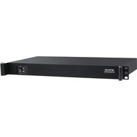
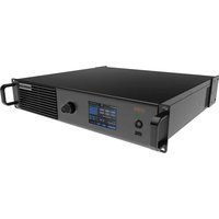
Phobos R5 - Contrôleur d'affichage LED NovaStar - Free user manual and instructions
Find the device manual for free Phobos R5 NovaStar in PDF.


| Product Type | LED Video Processor / Controller |
| Brand | NovaStar |
| Model | Phobos R5 |
| Input Signals | HDMI 2.0, DisplayPort 1.4, DVI, SDI |
| Output Signals | Ethernet (RJ45) to LED panels |
| Maximum Resolution | 3840 x 2160 @ 60Hz |
| Video Processing | Scaler, image cropping, color calibration (CalMAN support) |
| Control Software | NovaStar H-series software (MCTRL, H2, etc.) |
| Dimensions | 483 x 44 x 350 mm (1U rackmount) |
| Weight | 3.5 kg |
| Power Supply | AC 100-240V, 50/60 Hz, 120W max |
| Operating Temperature | 0°C to 45°C |
| Storage Temperature | -20°C to 60°C |
| Humidity | 10% to 90% (non-condensing) |
| Cooling | Fan, front-to-rear airflow |
| Connectivity | Ethernet, USB (for firmware update), RS232 |
| Mounting | 19-inch rack mount (1U) |
| Included Accessories | Power cable, rack ears, quick start guide |
| Maintenance | Clean with dry cloth; avoid liquids |
| Safety Certifications | CE, FCC, RoHS |
| Repairability | Modular design; replaceable fan and power supply unit |
Frequently Asked Questions - Phobos R5 NovaStar
User questions about Phobos R5 NovaStar
0 question about this device. Answer the ones you know or ask your own.
Ask a new question about this device
Download the instructions for your Contrôleur d'affichage LED in PDF format for free! Find your manual Phobos R5 - NovaStar and take your electronic device back in hand. On this page are published all the documents necessary for the use of your device. Phobos R5 by NovaStar.
USER MANUAL Phobos R5 NovaStar
| Document Version | Release Date | Description |
| V1.0.4 | 2022-09-21 | Updated the description of the image settings function. |
| V1.0.3 | 2021-11-26 | • Optimized the document content.• Changed the document style. |
| V1.0.2 | 2019-09-06 | Optimized the document content. |
| V1.0.1 | 2018-06-04 | Updated the document style. |
| V1.0.0 | 2016-06-06 | First release |
Contents
1 Overview....1
1.1 Introduction....1
1.2 Features....1
2 Appearance .... 2
3 Applications ....5
4 Cascade Devices....5
5 Home Screen....6
6 Menu Operations....7
6.1 Light a Screen Quickly....7
6.1.1 Step 1: Set Input Source....7
6.1.2 Step 2: Set Input Resolution ....7
6.1.3 Step 3: Quickly Configure the Screen....9
6.2 Brightness Adjustment 9
6.3 Screen Settings 10
6.3.1 Quick Configuration....10
6.3.2 Advanced Configuration....10
6.3.3 Image Offset....10
6.4 Image Rotation....11
6.5 Display Control....11
6.6 Advanced Settings....12
6.6.1 Mapping Function....12
6.6.2 Load Cabinet Configuration Files 13
6.6.3 Set Alarm Thresholds....13
6.6.4 Save to RV Card....14
6.6.5 Redundancy Settings....14
6.6.6 Presettings....14
6.6.7 Input Backup....14
6.6.8 Factory Reset....15
6.6.9 OLED Brightness 15
6.6.10 HW Version....15
6.7 Communication Settings....15
6.8 Language....16
7 Operations on PC....17
7.1 Software Operations on PC 17
7.1.1 NovaLCT 17
7.1.2 SmartLCT....17
7.2 Firmware Update....18
7.2.1 NovaLCT 18
7.2.2 SmartLCT....18
8 Specifications....19
1 Overview
1.1 Introduction
The MCTRL R5 is the first LED display controller of NovaStar that supports image rotation. A single MCTRL R5 features a load capacity of up to 3840×1080@60Hz. It supports any custom resolutions within this capacity, meeting the on-site configuration requirements of ultra-long or ultra-wide LED displays.
Working with the A8s or A10s Plus receiving card, the MCTRL R5 allows for free screen configuration and image rotation at any angle in SmartLCT, presenting a variety of images and bringing an amazing visual experience to users.
The MCTRL R5 is stable, reliable and powerful, dedicated to providing an ultimate visual experience. It can be mainly used in the rental and fixed installation applications, such as concerts, live events, security monitoring centers, Olympic Games and various sports centers.
1.2 Features
• A variety of input connectors
- 1x 6G-SDI
- 1 × HDMI 1.4
- 1x DL-DVI
- 8x Gigabit Ethernet outputs and 2x optical outputs
• Image rotation at any angle
Work with the A8s or A10s Plus receiving card and SmartLCT to support image rotation at any angle.
• Support for 8-bit and 10-bit video sources
- Pixel level brightness and chroma calibration
Working with NovaLCT and NovaCLB, the receiving card supports brightness and chroma calibration on each LED, which can effectively remove color discrepancies and greatly improve LED display brightness and chroma consistency, allowing for better image quality.
- Firmware update via USB port on the front panel
- Up to 8 devices can be cascaded.
Table 1-1 Feature constraints
| Feature | Constraints |
| Image rotation | A 10-bit input does not support image rotation.The screen must be configured on the MCTRL R5 before rotation setting in the LCD menu.The screen must be configured in SmartLCT before rotation setting in SmartLCT. |
2 Appearance
Front Panel

| No. | Name | Description | |
| 1 | “R5” indicator | Solid blue | The device is functioning normally. |
| Solid orange | The device has no signal input. | ||
| Breathing blue | The device is in standby mode. | ||
| Solid red | The device has an alarm. | ||
| 2 | OLED screen | Display the device status, menus, submenus and messages. | |
| 3 | Knob | On the home screen, press the knob to enter the main menu screen.On the main menu screen, rotate the knob to select a menu item or adjust the parameter value. Press the knob to confirm the operation. | |
| 4 | BACK | Go back to the previous menu. | |
| 5 | POWER | Standby button | |
| 6 | USB | A USB port used to connect a USB drive for firmware update | |
Rear Panel

| Connector Type | Connector Name | Description |
| Input | SDI | 1x 6G-SDI input connectorMaximum resolution: 3840 × 1080@60Hz Do NOT support interlaced signal input.Do NOT support input resolution settings or input bit depth settings. |
| HDMI | 1x HDMI 1.4 input connectorMaximum resolution: 3840 × 1080@60Hz Minimum resolution: 800 × 600@24Hz Custom resolutions supportedMaximum width: 3840 (3840 × 1080@60Hz) Maximum height: 3840 (800 × 3840@60Hz) Supported standard resolutions: 1024 × 768@(24/25/30/48/50/60/72/75/85/100/120)Hz 1280 × 720@(24/25/30/48/50/60/72/75/85/100/120)Hz 1280 × 1024@(24/25/30/48/50/60/72/75/85/100/120)Hz 1366 × 768@(24/25/30/48/50/60/72/75/85/100/120)Hz 1440×900@(24/25/30/48/50/60/72/75/85/100/120)Hz1536×1536@(24/25/30/48/50/60/72/75/85/100)Hz1600×1200@(24/25/30/48/50/60/72/75/85/100/120)Hz1920×1080@(24/25/30/48/50/60/72/75/85/100/120)Hz1920×1200@(24/25/30/48/50/60/72/75/85/100)Hz2048×640@(24/25/30/48/50/60/72/75/85/100/120)Hz2048×1152@(24/25/30/48/50/60/72/75/85/100)Hz2304×1152@(24/25/30/48/50/60/72/75/85/100)Hz2560×816@(24/25/30/48/50/60/72/75/85/100/120)Hz2560×1600@(24/25/30/48/50/60)Hz3840×1080@(24/25/30/48/50/60)HzSupport HDCP 1.4.Do NOT support interlaced signal input. | |
| DVI | 1x DL-DVI input connectorMaximum resolution: 3840×1080@60HzMinimum resolution: 800×600@24HzCustom resolutions supportedMaximum width: 3840 (3840×1080@60Hz)Maximum height: 3840 (800×3840@60Hz)Supported standard resolutions:1024×768@(24/25/30/48/50/60/72/75/85/100/120)Hz1280×720@(24/25/30/48/50/60/72/75/85/100/120)Hz1280×1024@(24/25/30/48/50/60/72/75/85/100/120)Hz1366×768@(24/25/30/48/50/60/72/75/85/100/120)Hz1440×900@(24/25/30/48/50/60/72/75/85/100/120)Hz1536×1536@(24/25/30/48/50/60/72/75/85/100)Hz1600×1200@(24(25/30/48/50/60/72/75/85/100/120)Hz1920×1080@(24/25/30/48/50/60/72/75/85/100/120)Hz1920×1200@(24/25/30/49/50/60/72/75/85/100)Hz2048×640@(24/25/30/48/50/60/72/75/85/100/120)Hz2048×1152@(24/25/30/48/50/60/72/75 85/100)Hz2304×1152@(24/25/30/48/50/60/72/75/85/100)Hz2560×816@(24/25/30/48/50/60/72/75/85/100/120)Hz2560 × 1600@(24/25/30/48/50/60)Hz3840×1080@(24/25/30/48/50/60)HzDo NOT support interlaced signal input. | |
| Output | 1-8 | 8x RJ45 Gigabit Ethernet portsMax capacity per port:- 8-bit inputs: 650,000 pixels- 10-bit inputs: 325,000 pixelsDo not support audio output.Support redundancy between Ethernet ports. |
| OPT1-OPT2 | 2× 10G optical portsOPT 1 copies and outputs the data on Ethernet ports 1-8.OPT 2 is the copy channel of OPT 1. | |
| Control | ETHERNETUSB IN-OUT | Connect to the control computer.IN: 1x type-B USB 2.0, used as the input port to cascade devices or connect to PC for device debugOUT: 1x type-A USB 2.0, used as the output port to cascade devices. Up to 8 devices can be cascaded. |
| GENLOCK IN-LOOP | A pair of Genlock signal connectors. Support Bi-Level, Tri-Level and Black burst.IN: Accept the sync signal.Loop: Loop the sync signal. | |
| Power | AC 100V~240V-50/60Hz | |
3 Applications
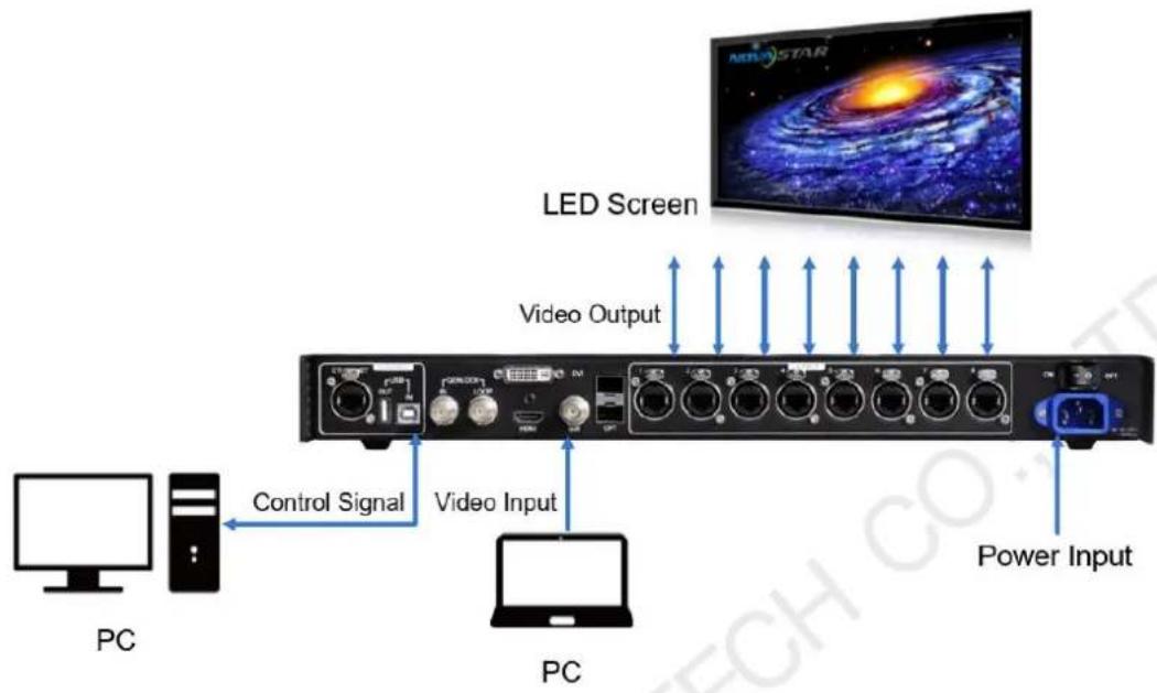
4 Cascade Devices
To control multiple MCTRL R5 devices simultaneously, follow the figure below to cascade them via the USB IN and USB OUT ports. Up to 8 devices can be cascaded.

flowchart
graph TD
    A["USB OUT IN"] --> B["USB OUT IN"]
    C["USB OUT IN"] --> D["USB OUT IN"]
    E["PC"] --> F["USB OUT IN"]
    style A fill:#f9f,stroke:#333
    style C fill:#f9f,stroke:#333
    style E fill:#f9f,stroke:#333
    style B fill:#ccf,stroke:#333
    style D fill:#ccf,stroke:#333
    style F fill:#ccf,stroke:#333
5 Home Screen
The figure below shows the home screen of the MCTRL R5.

| No. | Description | |
| 1 | The device name | |
| 2 | The resolution and refresh rate of the current input source | |
| 3 | IP Address | |
| 4 | Types of input sources supported and their connection statuses | |
| 5 | The working status of the Gigabit Ethernet portsBlack: The Ethernet port connection works and the port serves as master.White: The Ethernet port is not connected or the connection does not work.A mark in top corner of icon: The Ethernet port connection works and is in redundancy mode. | |
| 6/7 | Working status description: | |
 | Normal voltage and temperature / voltage alarm / temperature alarm / temperature and voltage alarm | |
 | Optical port working status:Black: The optical port connection works and the port serves as master.White: The optical port is not connected or the connection does not work. | |
 | Connection status of control ports:USB connected / Ethernet connected / GENLOCK connected | |
| [423T] | Screen brightness | |
 | Image rotation enabled / disabled | |
 | Front panel buttons locked / unlockedHold down the knob and BACK button simultaneously for 3s to lock or unlock all the front panel buttons. After the buttons are locked, all the button operations will not take effect and appears on the OLED screen. | |
6 Menu Operations
The MCTRL R5 is powerful and easy to use. You can quickly configure the LED screen to light it up and display the entire input source following steps in 6.1 Light a Screen Quickly. With other menu settings, you can further improve the LED screen display effect.
6.1 Light a Screen Quickly
Following the three steps below, namely Set Input Source > Set Input Resolution > Quickly Configure the Screen, you can quickly light up the LED screen to display the entire input source.
6.1.1 Step 1: Set Input Source
Supported input video sources include SDI, HDMI and DVI. Select an input source that matches the type of the inputted external video source.
Constraints:
- Only one input source can be selected at the same time.
- SDI video sources do not support the following functions:
- Preset resolution
- Custom resolution
- The 10-bit video sources are not supported when calibration function is enabled.
Figure 6-1 Input source

flowchart
graph LR
    A["Brightness 25% Screen Settings"] --> B["Input Settings"]
    C["Input Source"] --> D["Preset Resolution"]
    C --> E["Custom Resolution"]
    F["SDI"] --> G["DVI"]
    F --> H["HDMI"]
Step 1 On the home screen, press the knob to enter the main menu.
Step 2 Choose Input Settings > Input Source to enter its submenu.
Step 3 Select the target input source and press the knob to enable it.
6.1.2 Step 2: Set Input Resolution
Constraints: SDI input sources do not support input resolution settings.
The input resolution can be set through either of the following methods.
Method 1: Select a preset resolution
Select an appropriate preset resolution and refresh rate as the input resolution.
Figure 6-2 Preset resolution

flowchart
graph LR
    A["Brightness 25% Screen Settings"] --> B["Input Settings"]
    C["Input Source"] --> D["Preset Resolution"]
    D --> E["Custom Resolution"]
    F["Resolution"] --> G["Refresh Rate"]
    G --> H["Apply"]
Step 1 On the home screen, press the knob to enter the main menu.
Step 2 Choose Input Settings > Preset Resolution to enter its submenu.
Step 3 Select a resolution and refresh rate, and press the knob to apply them.
| Input Source | Available Standard Resolution Presets |
| HDMI 1.4 /DL-DVI | 1024 × 768@(24/25/30/48/50/60/72/75/85/100/120)Hz 1280 × 720@(24/25/30/48/50/60/72/75/85/100/120)Hz 1280 × 1024@(24/25/30/48/50/60/72/75/85/100/120)Hz 1366 × 768@(24/25/30/48/50/60/72/75/85/100/120)Hz 1440 × 900@(24/25/30/48/50/60/72/75/85/100/120)Hz 1536 × 1536@(24/25/30/48/50/60/72/75/85/100)Hz 1600 × 1200@(24/25/30/48/50/60/72/75/85/100/120)Hz 1920 × 1080@(24/25/30/48/50/60/72/75/85/100/120)Hz 1920 × 1200@(24/25/30/48/50/60/72/75/85/100)Hz 2048 × 640@(24/25/30/48/50/60/72/75/85/100/120)Hz 2048 × 1152@(24/25/30/48/50/60/72/75/85/100)Hz 2304 × 1152@(24/25/30/48/50/60/72/75/85/100)Hz 2560 × 816@(24/25/30/48/50/60/72/75/85/100/120)Hz 2560 × 1600@(24/25/30/48/50/60)Hz 3840 × 1080@(24/25/30/48/50/60)Hz |
Method 2: Customize a resolution
Customize a resolution by setting a custom width, height and refresh rate.
Figure 6-3 Custom resolution

Step 1 On the home screen, press the knob to enter the main menu.
Step 2 Choose Input Settings > Custom Resolution to enter its submenu and set the screen width, height and refresh rate.
Step 3 Select Apply and press the knob to apply the custom resolution.
6.1.3 Step 3: Quickly Configure the Screen
Follow the steps below to complete quick screen configuration.
Step 1 On the home screen, press the knob to enter the main menu.
Step 2 Choose Screen Settings > Quick Config to enter its submenu and set the parameters.
- Set Cabinet Row Qty and Cabinet Column Qty (numbers of cabinet rows and columns to be loaded) according to the actual situation of the screen.
- Set Port1 Cabinet Qty (number of cabinets loaded by Ethernet port 1). The device has restrictions on the number of cabinets loaded by the Ethernet ports. For details, see Note a).
- Set Data Flow of the screen. For details, see Note c), d), and e).
| Note: | |
| a). If n ports are used to load the screen, the number of cabinets loaded by each of the first (n-1) ports must be the same and the integral multiple of the number of cabinet rows or columns, and it must be greater than or equal to the number of cabinets loaded by the last port. | Example:If all the 8 Ethernet ports are used to load the screen, the number of cabinets loaded by ports 1–7 must be the same and the integral multiple of the number of cabinet rows or columns.Therefore, you need to set only the number of cabinets loaded by port 1 according to the actual situation. The number of cabinets loaded by port 8 must be less than or equal to the number of cabinets loaded by port 1. |
| b). For irregular screens, NovaLCT software must be connected to configure the screen. | |
| c). During data flow settings, you can rotate the knob to select a target data flow pattern. | |
| d). During data flow settings, ensure that the cabinets loaded by each Ethernet port are connected one by one in the same direction. | |
| e). During data flow settings, ensure that Ethernet port 1 is at the beginning position of the whole physical connection. | |
6.2 Brightness Adjustment
Screen brightness allows you to adjust the LED screen brightness in an eye-friendly way according to the current ambient brightness. Besides, appropriate screen brightness can extend the service life of the LED screen.
Figure 6-4 Brightness adjustment
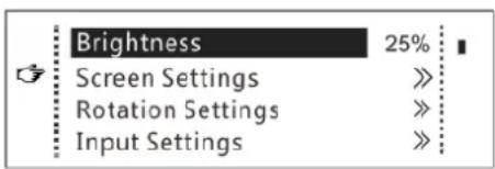
Step 1 On the home screen, press the knob to enter the main menu.
Step 2 Select Brightness and press the knob to confirm the selection.
Step 3 Rotate the knob to adjust the brightness value. You can see the adjustment result on the LED screen in real time. Press the knob to apply the brightness you set when you are satisfied with it.
6.3 Screen Settings
Configure the LED screen to ensure the screen can display the entire input source normally.
Screen configuration methods include quick and advanced configurations. There are constraints on the two methods, explained as below.
- The two methods cannot be enabled at the same time.
- After the screen is configured in NovaLCT, do not use any of the two methods on the MCTRL R5 to configure the screen again.
6.3.1 Quick Configuration
Configure the whole LED screen uniformly and quickly. For details, see 6.1 Light a Screen Quickly.
6.3.2 Advanced Configuration
Set parameters for each Ethernet port, including number of cabinet rows and columns (Cabinet Row Qty and Cabinet Column Qty), horizontal offset (Start X), vertical offset (Start Y), and data flow.
Figure 6-5 Advanced configuration

flowchart
graph LR
    A["Brightness 25% Screen Settings"] --> B["Quick Config Advanced Config Image Offset"]
    B --> C["Advanced Config Enable Port1 Setting Port2 Setting Port3 Setting"]
    C --> D["Port4 Setting Port5 Setting Port6 Setting Port7 Setting"]
    D --> E["Port8 Setting Apply"]
Step 1 Choose Screen Settings > Advanced Config and press the knob.
Step 2 In the caution dialog screen, select Yes to enter the advanced configuration screen.
Step 3 Enable Advance Config, select an Ethernet port, set the parameters for it, and apply the settings.
Step 4 Select the next Ethernet port to continue setting until all the Ethernet ports are set.
6.3.3 Image Offset
After configuring the screen, adjust the horizontal and vertical offsets (Start X and Start Y) of the overall display image to ensure it is displayed in the desired position.
Figure 6-6 Image offset

6.4 Image Rotation
There are 2 rotation methods: port rotation and screen rotation.
- Port rotation: Display rotation of cabinets loaded by Ethernet port (For example, set the rotation angle of port 1, and the display of cabinets loaded by port 1 will rotate according to the angle)
- Screen rotation: Rotation of the entire LED display according to the rotation angle
Figure 6-7 Image rotation

Step 1 On the home screen, press the knob to enter the main menu.
Step 2 Choose Rotation Settings > Rotation Enable, and choose Enable.
Step 3 Choose Port Rotate or Screen Rotate and set the rotation step and angle.
Note
• The screen must be configured on the MCTRL R5 before rotation setting in the LCD menu.
• The screen must be configured in SmartLCT before rotation setting in SmartLCT.
- After screen configuration is done in SmartLCT, when you set rotation function on the MCTRL R5, a message saying "Reconfig screen, are you sure?" will appear. Please choose Yes and perform rotation settings.
• A 10-bit input does not support image rotation.
• The rotation function is disabled when the calibration function is enabled.
6.5 Display Control
Control the display status on the LED screen.
Figure 6-8 Display control

flowchart
graph TD
    A["Display Control"] --> B["Advanced Settings"]
    A --> C["Communication Settings"]
    A --> D["Language"]
    E["Test Pattern"] --> F["Normal"]
    E --> G["Black Out"]
    E --> H["Freeze"]
    I["Image Settings"] --> J["Image Settings"]
● Normal: Display the content of the current input source normally.
- Black Out: Make the LED screen go black and do not display the input source. The input source is still being played in the background.
- Freeze: Make the LED screen always display the frame when frozen. The input source is still being played in the background.
- Test Pattern: Test patterns are used to check the display effect and pixel operating status. There are 8 test patterns, including pure colors and line patterns.
- Image Settings: Set the color temperature, brightness of red, green and blue, and gamma value of the image.
Note
The image settings function is disabled when the calibration function is enabled.
6.6 Advanced Settings
When this function is enabled, each cabinet of the screen will display the sequence number of the cabinet and the Ethernet port that loads the cabinet.
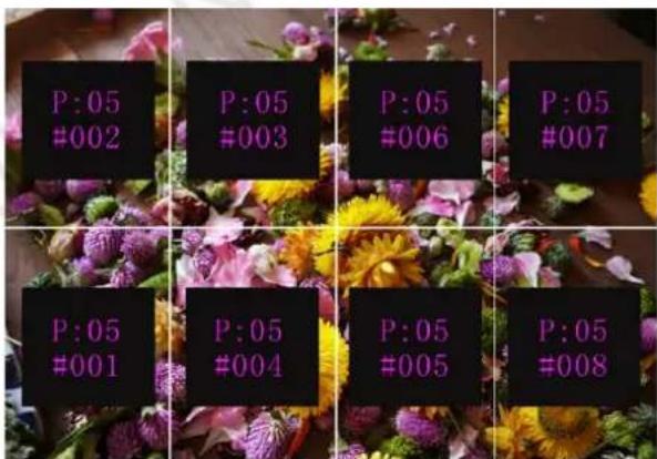
Example: "P:01" stands for the Ethernet port number and "#001" stands for the cabinet number.
Note
The receiving cards used in the system must support the Mapping function.
6.6.2 Load Cabinet Configuration Files
Before you begin: Save the cabinet configuration file (*.rcfgx or *.rcfg) to the local PC.
Step 1 Run NovaLCT and choose Tools > Controller Cabinet Configuration File Import.
Step 2 On the displayed page, select the currently used serial port or Ethernet port, click Add Configuration File to select and add a cabinet configuration file.
Step 3 Click Save the Change to HW to save the change to the controller.
Figure 6-10 Importing configuration file of controller cabinet

Note
Configuration files of irregular cabinets are not supported.
6.6.3 Set Alarm Thresholds
Set the alarm thresholds for device temperature and voltage. When a threshold is exceeded, its corresponding icon on the home screen will be flashing, instead of displaying the value.
Figure 6-11 Setting alarm thresholds

• : Voltage alarm, icon flashing. Voltage threshold range: 3.5 V to 7.5 V
• : Temperature alarm, icon flashing. Temperature threshold range: -20^ C to +85^ C
• Voltage and temperature alarms at the same time, icon flashing
Note
When there are no temperature or voltage alarms, the home screen will display the backup status.
6.6.4 Save to RV Card
By using this function, you can:
- Send and save the configuration information to the receiving cards, including brightness, color temperature, Gamma and display settings.
• Overwrite the information saved to the receiving card earlier. - Ensure that the data saved in the receiving cards will not be lost upon power failure of receiving cards.
6.6.5 Redundancy Settings
Set the controller as the primary or backup device. When the controller works as a backup device, set the data flow direction as opposite to that of the primary device.
Figure 6-12 Redundancy settings

Note
If the controller is set as the backup device, when the primary device fails, the backup device will immediately take over the work of the primary device, that is, the backup takes effect. After the backup takes effect, the target Ethernet port icons on the home screen will have marks in top flashing once every 1 second.
6.6.6 Presettings
Choose Advanced Settings > Presettings to save current settings as a preset. Up to 10 presets can be saved.
- Save: Save current parameters as a preset.
- Load: Read back the parameters from a saved preset.
- Delete: Delete the parameters saved in a preset.
6.6.7 Input Backup
Set a backup video source for each primary video source. Other input video sources supported by the controller can be set as backup video sources.
After a backup video source takes effect, the video source selection is irreversible.
| Primary Video source | Backup Video source |
| SDI | NULL/DVI/HDMI |
| DVI | NULL/SDI/HDMI |
| HDMI | NULL/DVI/SDI |
6.6.8 Factory Reset
Reset the controller parameters to factory settings.
6.6.9 OLED Brightness
Adjust the brightness of the OLED menu screen on the front panel. The brightness range is 4 to 15.
6.6.10 HW Version
Check the hardware version of the controller. If a new version is released, you can connect the controller to a PC to update the firmware programs in NovaLCT V5.2.0 or later.
6.7 Communication Settings
Set the communication mode and network parameters of the MCTRL R5.
Figure 6-13 Communication mode

flowchart
graph LR
    A["Display Control"] --> B["Communication Settings"]
    C["Advanced Settings"] --> B
    D["Communication Settings"] --> B
    E["Language"] --> B
    B --> F["Communication Mode"]
    B --> G["Network Settings"]
    F --> H["USB Preferred"]
    F --> I["LAN Preferred"]
● Communication mode: Include USB preferred and Local Area Network (LAN) preferred.
The controller connects to PC via USB port and Ethernet port. If USB Preferred is selected, the PC prefers to communicate with the controller via the USB port, or else via the Ethernet port.
Figure 6-14 Network settings

flowchart
graph TD
    A["Display Control"] --> B["Advanced Settings"]
    B --> C["Communication Settings"]
    C --> D["Language"]
    E["Communication Mode"] --> F["Network Settings"]
    F --> G["Network Settings"]
    G --> H["IP Address 192.168.0.10"]
    G --> I["Subnet Mask 255.255.255.0"]
    G --> J["Reset"]
    K["Manually"] --> L["Auto"]
- The network settings can be done manually or automatically.
- Manual setting parameters include controller IP address and subnet mask.
- Automatic settings can read the network parameters automatically.
- Reset: Reset the parameters to defaults.
6.8 Language
Change the system language of the device.
7 Operations on PC
7.1 Software Operations on PC
7.1.1 NovaLCT
Connect the MCTRL R5 to the control computer installed with NovaLCT V5.2.0 or later via USB port to perform screen configuration, brightness adjustment, calibration, display control, monitoring, etc. For details on their operations, see NovaLCT LED Configuration Tool for Synchronous Control System User Manual.
Figure 7-1 NovaLCT UI

7.1.2 SmartLCT
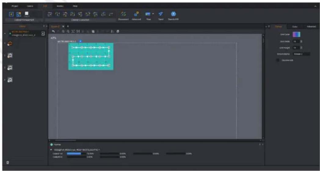
Connect the MCTRL R5 to the control computer installed with SmartLCT V3.4.0 or later via USB port to perform building-block screen configuration, seam brightness adjustment, real-time monitoring, brightness adjustment, hot backup, etc. For details on their operations, see the SmartLCT user manual.
Figure 7-2 SmartLCT UI
7.2 Firmware Update
7.2.1 NovaLCT
In NovaLCT, perform the following steps to update the firmware.
Step 1 Run the NovaLCT. On the menu bar, go to User > Advanced Synchronous System User Login. Enter the password and click Login.
Step 2 Type the secret code "admin" to open the program loading page.
Step 3 Click Browse, select a program package, and click Update.
7.2.2 SmartLCT
In SmartLCT, perform the following steps to update the firmware.
Step 1 Run SmartLCT and enter the V-Sender page.
Step 2 In the properties area on the right, click

nter the Firmware Upgrade page.
Step 3 Click to select the update program path.
Step 4 Click Update.
8 Specifications
| Electrical Specifications | Input voltage | AC 100V~240V-50/60Hz |
| Rated power consumption | 25 W | |
| Operating Environment | Temperature | -20^ C to +60^ C |
| Humidity | 10% RH to 90% RH, non-condensing | |
| Storage Environment | Temperature | -20^ C to +70^ C |
| Humidity | 10% RH to 90% RH, non-condensing | |
| Physical Specifications | Dimensions | 482.6 mm × 334.6 mm × 52.0 mm |
| Weight | 4.3 kg | |
| Packing Information | Carrying case | 530 mm × 370 mm × 140 mm |
| Accessory box | 405 mm × 290 mm × 48 mm1x Power cord, 1x Ethernet cable, 1x USB cable, 1x HDMI cable, 1x DVI cable | |
| Packing box | 550 mm × 400 mm × 175 mm |
Copyright © 2022 Xi'an NovaStar Tech Co., Ltd. All Rights Reserved.
No part of this document may be copied, reproduced, extracted or transmitted in any form or by any means without the prior written consent of Xi'an NovaStar Tech Co., Ltd.
Trademark
NOVA STAR is a trademark of Xi'an NovaStar Tech Co., Ltd.
Statement
Thank you for choosing NovaStar's product. This document is intended to help you understand and use the product. For accuracy and reliability, NovaStar may make improvements and/or changes to this document at any time and without notice. If you experience any problems in use or have any suggestions, please contact us via the contact information given in this document. We will do our best to solve any issues, as well as evaluate and implement any suggestions.



- Contents
- Overview
- Introduction
- Features
- Appearance
- Applications
- Cascade Devices
- Home Screen
- Menu Operations
- Light a Screen Quickly
- Step 1: Set Input Source
- Step 2: Set Input Resolution
- Method 1: Select a preset resolution
- Method 2: Customize a resolution
- Step 3: Quickly Configure the Screen
- Brightness Adjustment
- Screen Settings
- Quick Configuration
- Advanced Configuration
- Image Offset
- Image Rotation
- Note
- Display Control
- Advanced Settings
- Load Cabinet Configuration Files
- Set Alarm Thresholds
- Save to RV Card
- Redundancy Settings
- Presettings
- Input Backup
- Factory Reset
- OLED Brightness
- HW Version
- Communication Settings
- Language
- Operations on PC
- Software Operations on PC
- NovaLCT
- SmartLCT
- Firmware Update
- NovaLCT
- SmartLCT
- Trademark
- Statement
Brand : NovaStar
Model : Phobos R5
Category : Contrôleur d'affichage LED