
MX6000 Pro - Contrôleur d'affichage LED NovaStar - Free user manual and instructions
Find the device manual for free MX6000 Pro NovaStar in PDF.


| Product Type | 8K LED display controller |
| Model | MX6000 Pro |
| Brand | NovaStar |
| Dimensions (with foot pads) | 482.6 mm × 282.9 mm × 538.8 mm (19.0 × 11.1 × 21.2 in) |
| Net Weight (without cards) | 31 kg (68.3 lb) |
| Power Supply | 100-127 V or 200-240 V AC, 15 A / 10 A, 50/60 Hz |
| Power Consumption | 625 W |
| Max Load Capacity | 141 million pixels |
| Video Inputs (max config) | Up to 32× 4K or 8× 8K |
| Color Depth | 12-bit |
| Refresh Rate | Up to 360 Hz |
| HDR Support | HDR10, HLG |
| Input Card Options | HDMI 2.0, HDMI 2.1, DP 1.2, DP 1.4, 12G-SDI, VoIP |
| Output Card Options | 4× 10G Fiber or 1× 40G Fiber |
| Control Software | VMP (Vision Management Platform) |
| Front Panel Display | 7-inch IPS touchscreen |
| Operating Temperature | -10°C to +60°C (14°F to 140°F) |
| Storage Temperature | -10°C to +60°C (14°F to 140°F) |
| Humidity (Operating/Storage) | 0%–80% RH / 0%–90% RH, non-condensing |
| IP Rating | IP20 |
Frequently Asked Questions - MX6000 Pro NovaStar
User questions about MX6000 Pro NovaStar
0 question about this device. Answer the ones you know or ask your own.
Ask a new question about this device
Download the instructions for your Contrôleur d'affichage LED in PDF format for free! Find your manual MX6000 Pro - NovaStar and take your electronic device back in hand. On this page are published all the documents necessary for the use of your device. MX6000 Pro by NovaStar.
USER MANUAL MX6000 Pro NovaStar
natural_image
Abstract graphic with a human eye and colorful triangular shapes, no text or symbols present.User Manual
Change History
| Document Version | Release Date | Description |
| V1.1.1 | 2023-10-13 | Updated input cards information |
| V1.1.0 | 2023-09-28 | Added information for HDMI 2.1 and 12G-SDI input cards |
| V1.0.1 | 2023-09-08 | Added accessory information |
| V1.0.0 | 2023-08-03 | First release |
Contents
Change History ....i
Contents ...... ii
1 Introduction....1
2 Appearance....2
2.1 Front Panel....2
2.2 Rear Panel .... 3
3 Applications....8
3.1 Solution Build 8
3.2 1G Solution (MX_4x10G_Fiber Output Card)....8
3.3 5G Solution (CX_1x40G_Fiber Output Card) 9
4 VMP Operations....10
4.1 Connect to VMP 10
4.2 UI Introduction....10
4.3 Device Management....11
4.3.1 Export and Import Project Files.... 11
4.3.2 Manage Device Groups 12
4.3.3 Set Backup Device 12
4.4 Screen Configuration....13
4.4.1 New Screen....13
4.4.2 Configure Screen Topology....14
4.4.3 Set Card Backup....18
4.4.4 Set the Cabinet....19
4.5 Input Source Configuration....20
4.5.1 Add Layers....20
4.5.2 Set External Sources....21
4.5.3 Set Internal Sources 24
4.6 Display Correction 25
4.6.1 Correct Seams....25
4.6.2 Correct Multi-Batch Cabinets/Modules 26
4.6.3 Lock and Unlock Correction Page 28
4.7 Color Processing 28
4.7.1 Color Replacement....28
4.7.2 14Ch Color Correction 29
4.7.3 Set Color Curves 30
4.7.4 Enable 3D LUT 30
4.8 Screen Settings....31
4.8.1 Adjust Image Quality....31
4.8.1.1 Adjust Brightness and Gamma 31
4.8.1.2 Set LED Image Booster 31
4.8.1.3 Apply Calibration Effect....32
4.8.1.4 Set Thermal Compensation 32
4.8.2.1 Set Output Bit Depth and Additional Frame Latency....33
4.8.2.2 Set Sync Parameters....34
4.8.2.3 Set Frame Multiplication 34
4.8.2.4 Set Shutter Fit....35
4.8.2.5 Enable 3D Function ....35
4.8.2.6 Check the Load....36
4.9 Preset Management....36
4.9.1 Save Presets 36
4.9.2 Apply Presets....37
4.9.3 Manage Presets....37
4.9.4 Import and Export Presets 38
4.10 Screen Monitoring .... 38
4.10.1 Check Device Status 38
4.10.2 Check Monitoring Records 39
4.11 Calibration Coefficient Management....40
4.11.1 Upload Calibration Coefficients....40
4.11.2 Edit Calibration Coefficients....42
4.11.3 12.3 View Calibration Effect....43
4.11.4 Save Calibration Coefficients....44
4.11.5 Read Back Calibration Coefficients....45
4.11.6 Export Calibration Coefficients....46
4.12 Screen Maintenance....47
4.12.1 Maintain Controllers....47
4.12.2 Maintain Cabinets....49
4.13 Software Settings 51
4.13.1 Offline Mode 51
4.13.2 14.1 Change Language and Temperature Scale ....52
4.13.3 Manage Cabinet Library ....52
4.13.4 14.3 Check User Manual ....54
4.13.5 14.4 Check Software Information....54
4.13.6 Check Keyboard Shortcuts....54
5 Front Screen Panel....55
5.1 UI Introduction....55
5.1.1 Home Screen....55
5.1.2 Main menu....57
5.2 Screen....58
5.2.1 Set Brightness, Color Temperature and Gamma 58
5.2.2 Set Screen Status....58
5.3 Input 59
5.3.1 Set Internal Source....59
5.3.2 Check Input Source Information .... 59
5.3.3 Set EDID....60
5.3.4 Set HDR 61
5.4 Communication 61
5.5 Settings 62
5.5.1 Configure LCD Screen....62
5.5.2 Setting Language....62
5.5.3 Set Temperature Scale 63
5.5.4 Check Firmware Information....63
5.5.5 Factory Reset 64
5.6 Maintenance....64
5.6.1 Diagnostics 64
5.6.2 View and Export Logs....65
5.6.3 Check Device Status 65
6 Specifications....67
7 Video Source Specifications 68
8 Ethernet Port Load Capacity 70
8.1 1G Solution (MX_4x10G_Fiber Output Card)....70
8.2 5G Solution (CX_1x40G_Fiber Output Card)....71
1 Introduction
The MX6000 Pro is a large professional 8K LED display controller from Xi'an NovaStar Tech Co., Ltd. (hereinafter referred to as NovaStar), designed as part of the COEX control system series. Its remarkable features include 12-bit color depth, 360 Hz capability, real-time multi-screen scaling, 0-frame latency, and HDR supportability, providing precise brightness control, true-to-life color fidelity, and an excellent image quality. Its card-based modular design is specifically tailored for future LED displays, allowing for flexible input and output card configurations that are stable and easy to maintain. With a compact 6U size, it supports up to 32x 4K or 8x 8K video inputs, with a maximum load capacity of 141 million pixels, making it ideal for large-screen configurations.
The MX6000 Pro offers a wide range of options with up to six different input cards supporting 8K, 4K, and VoIP. For output, it supports two types of output cards: 4x 10G fiber and 1x 40G fiber. These cards can be configured flexibly to accommodate either 1G or 5G bandwidth for the control system, catering to different requirements. Additionally, it supports seamless backup and automatic switching between devices and cards. In case of any malfunction, it promptly switches over while issuing automatic alerts, ensuring stable output on-site. To further enhance the user experience, it is complemented by the advanced control software, VMP, enabling users to have better control and management capabilities.
The MX6000 Pro offers many advantages such as highly integrated design, premium image quality, powerful performance, tremendous load capacity, and easy control. It is widely used in rental services for large events, xR/VP studios, large fixed installation applications, TV production, e-sports events, exhibition halls, and other application scenarios.
2 Appearance
2.1 Front Panel

| Description | Function |
| Running indicator | Solid red: Standby.Solid blue: The device is being powered on.Solid green: The device is running normally.Flashing red: The device is running abnormally. |
| Standby button | Press the button to power on or power off the device.Hold down the button for 5s to 10s to restart the device. |
| USB 2.0 | Connect to a USB drive only to export the device diagnostic result.Only the NTFS and FAT32 file systems are supported. Others are not supported. |
| IPS touchscreen | A 7-inch screen that is for displaying the device status, setting parameters, and sending commands. |
| Knob | On the home screen, press the knob to enter the main menu screen.On the main menu screen, rotate the knob to select a menu item or adjust the parameter value. Press the knob to confirm the operation.Hold down the knob and BACK button simultaneously for 5s or longer to lock or unlock the buttons and screen. |
| BACK | Go back to the previous menu or cancel the current operation. |
2.2 Rear Panel
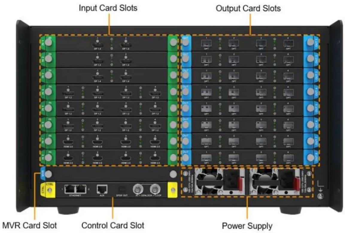
All product pictures shown in this document are for illustration purpose only. Actual product may vary.

Note
Markings on the rear panel card slot:
- The card slot marked with "IN x" only supports the installation of input cards, where x is the slot number. For example, IN 1 indicates the first input card slot.
- The card slot marked with "OUT x" only supports the installation of output cards, where x is the slot number. For example, OUT 6 indicates the sixth output card slot.
• The card slot marked with "MVR" only supports the installation of MVR cards.
• The card slot marked with "CTRL" only supports the installation of control cards.
| Input Card | |||
| MX_4× HDMI 2.0 input card | |||
| Type | Qty | Description | |
| HDMI 2.0 | 4 | Resolution | Max resolution: 4096×2160@60Hz or 8192×1080@60Hz (Forced)Min resolution: 800×600@60Hz |
| Max width/height(Forced) | Max width: 8192 pixels (8192×1080@60Hz)Max height: 8192 pixels (1080×8192@60Hz) | ||
| Frame rates | 23.98 / 24 / 25 / 29.97 / 30 / 47.95 / 48 / 50 / 59.94 / 60 / 71.93 / 72/ 75 / 100 / 119.88 / 120 / 143.86 / 144 / 240 Hz | ||
| HDR | Support HDR10 and comply with the SMPTE ST 2084 and SMPTE ST 2086 standards. | ||
| Support HLG. | |||
| EDID management | Support standard resolutions, up to 3840×2160@60Hz.Support custom input resolutions. | ||
| HDCP | Support HDCP 2.3, backwards compatible with HDCP2.2/ HDCP 1.4/ HDCP 1.3. | ||
| Interlaced signal inputs | Not supported. | ||
| MX_2× HDMI 2.1 input card | |||
 | |||
| Type | Qty | Description | |
| HDMI 2.1 | 2 | Resolution | Max resolution: 8192×4320@30Hz (Forced)Min resolution: 800×600@60Hz |
| Max width/height (Forced) | Max width: 8192 pixels (8192×4320@30Hz)Max height: 8192 pixels (4320×8192@30Hz) | ||
| Frame rates | 23.98 / 24 / 25 / 29.97 / 30 / 47.95 / 48 / 50 / 59.94 / 60 / 71.93 / 72 / 75 / 100 / 119.88 / 120 / 143.86 / 144 / 240 Hz | ||
| HDR | Support HDR10 and comply with the SMPTE ST 2084 and SMPTE ST 2086 standards.Support HLG. | ||
| EDID management | Support standard resolutions, up to 3840×2160@60Hz.Support custom input resolutions. | ||
| HDCP | HDCP 2.3 compliant, backwards compatible with HDCP 2.2/HDCP 1.4/HDCP 1.3. | ||
| Interlaced signal inputs | Not supported | ||
| MX_4× DP 1.2 input card | |||
| INDP 1.2 | 2DP 1.2 | 3DP 1.2DP 1.2 | |
| Type | Qty | Description | |
| DP 1.2 | 4 | Resolution | Max resolution: 4096×2160@60Hz or 8192×1080@60Hz (Forced)Min resolution: 800×600@60Hz |
| Max width/height (Forced) | Max width: 8192 pixels (8192×1080@60Hz)Max height: 8192 pixels (1080×8192@60Hz) | ||
| Frame rates | 23.98 / 24 / 25 / 29.97 / 30 / 47.95 / 48 / 50 / 59.94 / 60 / 71.93 / 72 / 75 / 100 / 119.88 / 120 / 143,86 / 144 / 240 Hz | ||
| HDR | Support HDR10 and comply with the SMPTE ST 2084 and SMPTE ST 2086 standards. | ||
| MX_2× DP 1.4 input card | |||
 | |||
| DP 1.4 | 2 | Resolution | Max resolution: 7680×4320@30Hz (Forced)Min resolution: 800×600@60Hz |
| Max width/height (Forced) | Max width: 8192 pixels (8192×4320@25Hz)Max height: 8192 pixels (4320×8192@25Hz) | ||
| Frame rates | 23.98 / 24 / 25 / 29.97 / 30 / 47.95 / 48 / 50 / 59.94 / 60 / 71.93 / 72 / 75 / 100 / 119.88 / 120 / 143.86 / 144 / 240 Hz | ||
| HDR | Support HDR10 and comply with the SMPTE ST 2084 and SMPTE ST 2086 standards.Support HLG. | ||
| EDID management | Support standard resolutions, up to 3840×2160@60Hz.Support custom input resolutions. | ||
| HDCP | Support HDCP 2.3, backwards compatible with HDCP2.2/ HDCP 1.4/ HDCP 1.3. | ||
| Interlaced signal inputs | Not supported. | ||
| MX_4× 12G-SDI input card | |||
 | |||
| Type | Qty | Description | |
| 12G-SDI | 4 | Standards | Support ST-2082 (12G), ST-2081 (6G), ST-424 (3G) and ST-292 (HD) standard video inputs.Support 3G-Level A/Level B (DS mode). |
| Resolution | Max resolution: 4096×2160@60Hz | ||
| Frame rate | Support frame rates up to 60Hz. | ||
| HDR | Support HDR10 and comply with the SMPTE ST 2084 and SMPTE ST 2086 standards.Support HLG. | ||
| Interlaced signal inputs | Support converts interlaced signals to progressive signals. | ||
| Others | Belden 12G SDI standard cables are recommended. Cables up to 50 meters are supported. | ||
| Output Card | ||
| MX_4×10G_Fiber output card | ||
 | ||
| Type | Qty | Description |
| OPT 1-4 | 4 | 10G optical portsSupport single-mode and multi-mode optical fiber modules, with a maximum transmission distance of 10km.A single optical port can load up to 10 channels of 1G Ethernet ports, and a single card can support up to 40 channels of Ethernet port output.The maximum load of a single 1G Ethernet port is as follows:-8bit@60Hz: 659,722 pixels-10bit@60Hz: 494,791 pixels (available only with the A10s Pro receiving card)-10/12bit@60Hz: 329,861 pixels |
| MX_1×40G_Fiber output card | ||
| Type | Qty | Description |
| OPT 1 | 1 | 40G optical portSupport single-mode and multi-mode optical fiber modules, with a maximum transmission distance of 10km.A single optical port/A Single card can load up to 8 channels of 5G Ethernet portsThe maximum load of a single 5G Ethernet port is as follows:-8bit@60Hz: 2,592,000 pixels-10bit@60Hz: 2,073,000 pixels-12bit@60Hz: 1,728,000 pixels |
| Control card | |||
 |  |  | [00VT] 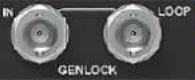 |
| Type | Qty | Description | |
| ETHERNET | 2 | Gigabit Ethernet control ports. Support TCP/IP protocol and star connection.They have the same functions without priority and order, and can be connected to VMP software. No switch or router is needed to deploy multiple devices on the same LAN via device cascading as the network switching function is already built in. Up to 20 MX20 devices can be cascaded. | |
| GENLOCK | 1 | A pair of Genlock signal connectors. Support Bi-Level and Tri-Level.IN: Accept the sync signal.Loop: Loop the sync signal.For standard Genlock signal generators, up to 20 MX20 devices can be cascaded. | |
| AUX | 1 | An auxiliary connector that connects to the central control device (RS232) (Reserved) | |
| SPDIF | 1 | A digital audio output (Reserved) | |
| MX_MVR output card | |||
| Power | |||
| Type | Qty | Description | |
| 100-127V~/200-240V~,15A/10A, 50/60Hz | 2 | An AC power input connector and switch | |
3 Applications
3.1 Solution Build
Based on the installed output cards (MX_4x10G_Fiber output card/CX_1x40G_Fiber output card), users can build 1G/5G solutions with different models of fiber converters and receiving cards. 1G/5G refers to the output bandwidth of a single Ethernet port. For more detailed information, please refer to 8 Ethernet Port Load Capacity.
Table 3-1 COEX system build
| Solution | Output Card | Fiber Converter | Receiving card |
| 1G solution | MX_4x10G_Fiber output card | CVT10, CVT10 Pro | 1G receiving cards such as A10s Pro |
| 5G solution | CX_1x40G_Fiber output card | CVT8-5G | 5G receiving cards such as CA50E |

It would not be possible to build both 1G and 5G solutions with an MX6000 Pro at the same time.
3.2 1G Solution (MX\_4x10G\_Fiber Output Card)

flowchart
graph TD
    A["LED Screen"] --> B["40x 1G Ethernet"]
    B --> C["4x CVT 10 Fiber Converter"]
    C --> D["4x 10G OPT"]
    D --> E["HDMI Input"]
    D --> F["DP Input"]
    D --> G["SDI Input"]
    D --> H["SMPTEST 2110 Input"]
    E --> I["Switch"]
    F --> J["Router"]
    G --> K["PC"]
    H --> L["n×PC"]
This diagram is an example of four input cards and one MX_4x10G_Fiber output card installed on an MX6000 Pro. The actual application may vary.
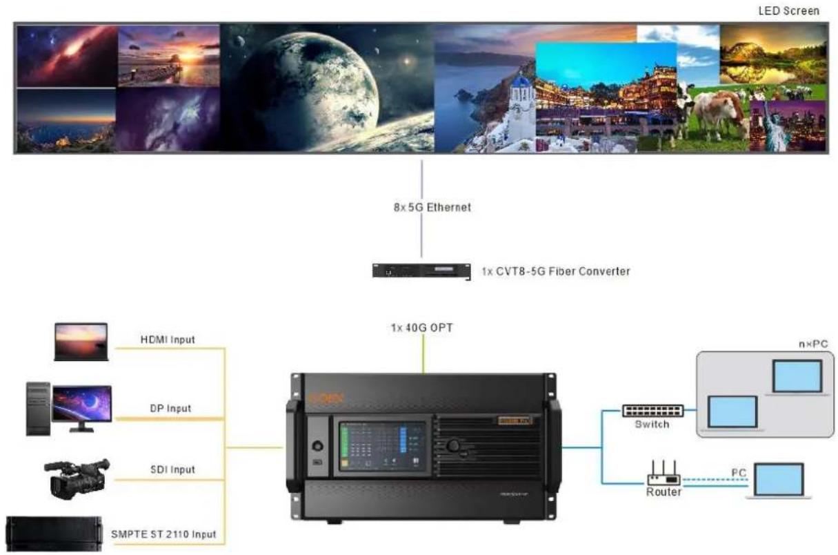
3.3 5G Solution (CX\_1x40G\_Fiber Output Card)
flowchart
graph TD
    A["LED Screen"] --> B["8x5G Ethernet"]
    B --> C["1x CVT8-5G Fiber Converter"]
    C --> D["HDMI Input"]
    C --> E["DP Input"]
    C --> F["SDI Input"]
    C --> G["SMPTE ST 2110 Input"]
    D --> H["Server with HDMI/DP/SDI/SPMTE"]
    E --> H
    F --> H
    G --> H
    H --> I["Switch"]
    H --> J["Router"]
    I --> K["n×PC"]
    J --> L["PC"]
This diagram is an example of four input cards and one CX_1x40G_Fiber output card installed on an MX6000 Pro. The actual application may vary.
4 VMP Operations
Users can only perform some basic operations on the LCD screen of MX6000 Pro. To perform more operations, please install Vision Management Platform (VMP) on the control PC.
4.1 Connect to VMP
Via Ethernet Cable
Connect the controller and the control PC directly using an Ethernet cable, and assign a static IP address to the controller to ensure that the controller and control PC are on the same network segment.
Via LAN
Connect the controller and the control PC to the same LAN and set the controller to automatically obtain an IP address.
4.2 UI Introduction
Figure 4-1 UI Introduction

Note:
All the figures in this document use operations in Windows10 as examples.
You can refer to section 4.6.3 Lock and Unlock Correction Page to lock the Correction page to avoid changing the display content due to misoperation.
4.3 Device Management
4.3.1 Export and Import Project Files
Export the project files (.nprj) of devices or device groups so that you can import the files to apply the configuration data to the same kind of devices, improving the configuration efficiency.
Notice
The project file can be imported to the device that is of the same model and share the first two digits of the firmware version.
For example, the project file of V1.3.0 can be imported to the devices whose firmware version is V1.3.1.
Export Project Files
Step 1 From the menu bar, choose Project > Export and select a device or device group.
You can also right-click a device or device group in the device list and select Export from the pop-up menu.
Step 2 Select a local directory and click Save.
Figure 4-2 Successful export

Import Project Files
Step 1 From the menu bar, choose Project > Import to and select a device or device group.
You can also right-click a device or device group in the device list and select Import from the pop-up menu.
Step 2 Select a local project file and click Open.
After successful device matching, a dialog box as shown in Figure 4-3 is displayed.
Figure 4-3 Matching devices

Step 3 Click OK.
Figure 4-4 Successful import

4.3.2 Manage Device Groups
Optimize device management by creating device groups, which will enable uniform management and batch operations on multiple devices within the same group.
Notice
Only devices of the same model and firmware version can be grouped.
Operating Procedure
Step 1 In the device list area, click Manager the group management page.
Figure 4-5 Group management

Step 2 Click ☐ to create a group, enter a group name and press Enter or click any empty space on the page. To rename a group, right-click the group, select Rename from the pop-up menu and enter a new group name.
Step 3 Drag the target devices to the created group. Controllers of different models or firmware versions cannot be grouped.
Step 4 After the settings, click

• To delete a device in a group, drag the device out of the group.
- To delete a group, right-click the group, select Remove group from the pop-up menu.

You can set the Mapping switch to enable the mapping function
4.3.3 Set Backup Device
Enhance system reliability by establishing a primary controller and backup controller, allowing the backup controller to take over responsibility in case of primary controller failure.
Step 1 From the menu bar, choose Tools > System Backup to open the System Backup dialog box.
You can also right-click a device or device group in the device list and select System backup from the pop-up menu to open the System Backup dialog box.
Figure 4-6 System backup
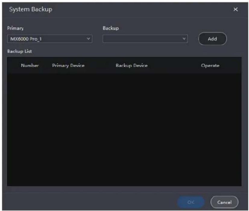
Step 2 Select a primary controller and a backup controller from the drop-down options respectively, and then click Add.
The backup list will display the added backup information. To delete the backup information, click
Step 3 After the settings, click OK.
4.4 Screen Configuration
4.4.1 New Screen
Step 1 Select the controller from the device list and then select Layout.
Figure 4-7 Layout
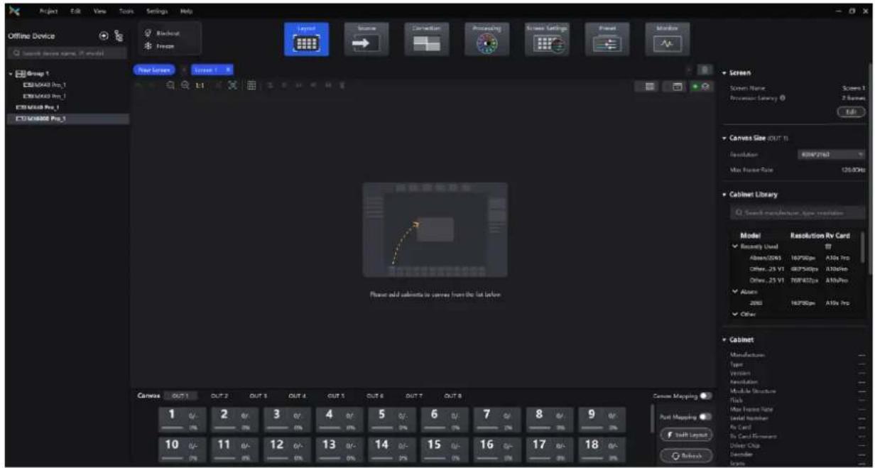
Step 2 Click New Screen.
Step 3 Enter a screen name on the pop-up window.
Figure 4-8 New Screen

Step 4 Select a Working Mode. When operating as a Send-Only Controller, please configure the layer layout as well.
All-In-One Controller supports free layer layout; Send-Only Controller is subject to fixed layer layout.
Step 5 Set low latency.
When low latency is set to , the latency at the data-sending end is reduced by 1 frame.
Step 6 Click OK once you are done.
Related Operations:
- Edit screen: Click Edit in the Screen section of the properties area.
- Delete screen: click ✗ on the right side of the screen tab or in the top right corner of the topology area.
- Select multiple screens: Hold Ctrl and click on the screen names.
4.4.2 Configure Screen Topology
Step 1 Select the controller from the device list and then select Layout.
Step 2 Select a view by clicking one of the following icons at top right of the topology area.
• : Show the cabinets only.
• : Show the preview image of the input source only.
• : Show the cabinets and preview image of the input source at the same time.
Note
You can also select a view from the menu bar > View > Display and choose the content to be displayed, including cabinet topology, cabinet status, group names, source tags, and overlapping cabinets.
Step 3 Select a screen.
Step 4 Select a canvas at the bottom of the page. First click on any output port of the canvas, and then click on the topology area to place the canvas.
Each canvas corresponds to an output card. For example, the three canvases OUT 1, OUT 2, and OUT 3 in Figure 4-9 correspond to three output cards respectively.
Figure 4-9 Canvas

Related Operations:
- Set canvas resolution: Select a canvas at the bottom of the page and then set the canvas resolution in the properties area.
- Move Canvas: Click and hold the name at the top left of the canvas in the topology area, then drag it to the desired position.
- Delete: Canvas: Click on the name at the top left of the canvas in the topology area to select it, then press Delete.
- Locate Canvas: Set Canvas Mapping to ☐, so that the canvas position can be quickly viewed on the LED screen.
Step 5 After placing a canvas, you can drag or click the mouse in the topology area to add cabinets.
The cabinets will be automatically connected when you are adding them, as shown in Figure 4-10. The Ethernet port's load capacity information will be displayed, as shown in Figure 4-11. The properties area will display the cabinet information, as shown in Figure 4-12.
Figure 4-10 Cabinets connected automatically
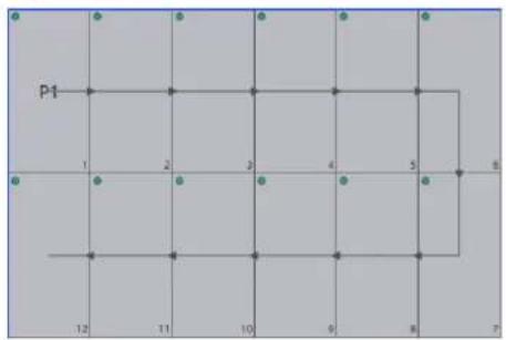
Figure 4-11 Ethernet port capacity

- 8/-: Indicates that 8 cabinets of the Ethernet port are added to the topology.
- 45%: Indicates these 8 cabinets have used 45% of the Ethernet port's capacity.
Figure 4-12 Cabinet Information
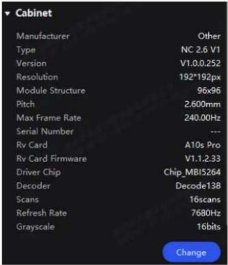

Note
If all the cabinets loaded by the Ethernet ports have the same size, you can use the swift layout function to quickly add and connect the cabinets for all the Ethernet ports.
The operations are as follows:
Click Swift Layout and then drag the mouse on the canvas to add cabinets that match the actual requirements. In the properties area, select a layout and click Done.
Step 6 Select another Ethernet port and continue to add cabinets until all cabinets are connected.
To change the cabinet model, simply select the cabinet and then click Change in the property area.
Step 7 For cabinets that have the same size and consecutive serial numbers, if you want to change the cabinet connection topology, select the cabinets and then select a quick topology under Quick topo in the properties area, as shown in Figure 4-13. For other cabinets, skip this step.
Figure 4-13 Quick topology

Step 8 Do any of the following to arrange and align the cabinets to let the cabinet positions meet the display requirements.
Use the function buttons
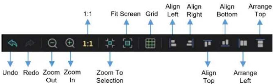
- 1:1: The canvas size equals to the input source resolution.
- Zoom to Selection: The selected element is zoomed and displayed in the center of the canvas.
- Fit Screen: The canvas size is automatically adjusted to fit the topology area size.
Click to show its drop-down menu shown below. The menu can be used to set the canvas grid.

- Grid: When toggled on (○), a grid is displayed on the canvas. If you do not need to display the grid, set the switch to ○
- Color: Set the grid color.
- Spacing: Set the spacing of horizontal and vertical lines of the grid. The spacing is set to the resolution of the first cabinet by default.
- Snap to Cabinet: When positioning a cabinet near another one, the cabinet being moved will automatically align and snap to the edge of the adjacent cabinet, effectively eliminating gaps.
- Snap to Grid: The cabinet will be snapped to the grid.
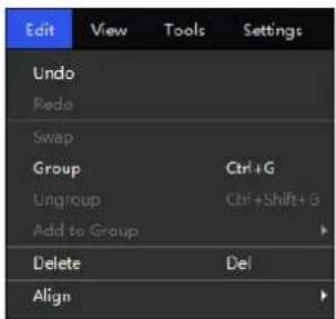
Use the function menus on the menu bar
- Edit menu
- View menu

Use the right-click function menus
- Right-click the canvas
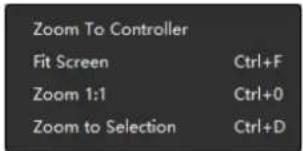
Zoom to Controller: The selected controller is zoomed and displayed in the middle of the topology area.
- Right-click the cabinet

Select String: Select all the cabinets on the connection line of the current cabinet.
Swap: Swap the positions of the two selected cabinets.
Group: Group the selected cabinets. To set the group name and color, please select the group and set them in the properties area.
Ungroup: Ungroup the cabinets.
Add to Group: Add the selected cabinets to a group.
Set cabinet coordinates and rotation
Select a cabinet and set its coordinates and rotation angle in the properties area. After the cabinet is rotated, the input source will be rotated by the set angle and displayed.

Step 9 Set the cabinet topology for other canvases.
4.4.3 Set Card Backup
Step 1 Select the controller from the device list and then select Layout.
Step 2 In the properties area, select a backup for the card.
Figure 4-14 Backup settings
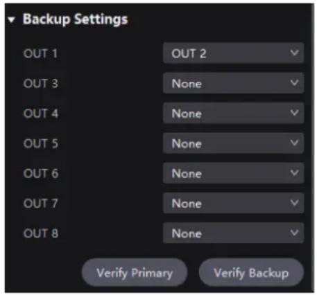
Step 3 Click Verify Primary or Verify Backup to examine whether the channel is working properly.
- Verify Primary: Disconnect the backup channel and examine whether the primary channel is working properly.
- Verify Backup: Disconnect the primary channel and examine whether the backup channel is working properly.
4.4.4 Set the Cabinet
Select the controller from the device list and then select Layout. Select one or more cabinets and do any of the following operations in the properties area.
Figure 4-15 Cabinet settings
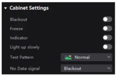
Control Display Status
Set the Blackout or Freeze switch to .
Enable Indicator
Set the Indicator switch to enable the running status indicator of the cabinet.
Enable the Light Up Slowly Function
Set the Light up slowly switch to 📄 so that after the screen is powered on, the display brightness will slowly change from 0 to the target value.
Set Test Pattern
Select a test pattern from the drop-down list of Test Pattern to perform screen aging test and troubleshoot problems.
Set Image for Abnormal Situations
Select an option from the No Data signal drop-down list.
- Blackout: The screen displays a black image.
- Last Frame: The screen always displays the last frame.
4.5 Input Source Configuration
4.5.1 Add Layers
Step 1 Select the controller from the device list and then select Source.
Figure 4-16 Input source

Step 2 Select an input card at the bottom of the page.
Step 3 Double-click the thumbnail of the input source or drag the input source to the target position to add a layer. (Remember to select a canvas first if there are multiple canvases).
All-In-One Controller supports free layer layout; Send-Only Controller is subject to fixed layer layout and when adding a layer, it will automatically fill the canvas and the size and position of the layer cannot be adjusted.
You can check the source status according to the source indicator:
• Green: The input source is connected.
- Red: The input source is applied for the screen but not connected.
- Gray: The input source is not connected.
Step 4 Make layer adjustments as needed.
Lock layer

Switch source
- Select a layer and select another source in the properties area.

- Right-click a layer, select Source from the displayed menu, and select another source.
Adjust layer size and position
- Select a layer and set the layer size and coordinates in the properties area. You can also bring the layer to front or send it to back.

- Right-click a layer and select Bring to Front, Send to Back, Bring Forward or Send Backward from the displayed menu.
- At the top right of a layer, click a function icon to set the layer.
: Lock the layer.
: Unlock the layer.
1: The layer size is the same as the input source resolution.
☐: The layer automatically fill the screen.
The layer size changes automatically according to the canvas size.
X: Delete the layer.
Set borders
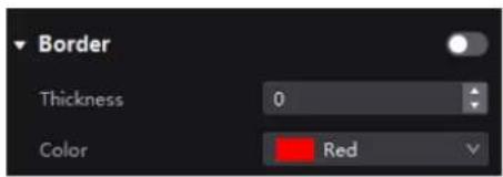
Select a layer and enable or disable the layer borders function in the properties area. After enabling the function, you can set the border thickness and color.
Crop the input source
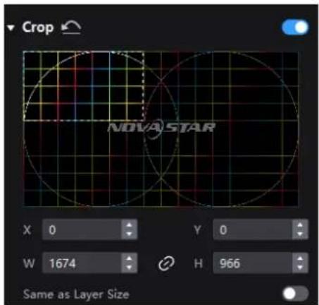
Select a layer and enable or disable the Crop function in the properties area. Then, you can set the crop size and position on the thumbnail of the layer. You can also make adjustments by setting the parameter values below the thumbnail. When Same as Layer Size is set to ☐, the input source image will be cropped according to the layer size.
4.5.2 Set External Sources
Select the controller from the device list and then select Source. Select an external source from the source list and do the following as required.
Set DP 1.4 Mode
Select an option from the drop-down list to calculate the layer resources for the DP 1.4 connector.
- 8192*2160@60Hz: Up to 2 layers can be added.
- 4096*2160@60Hz: Up to 4 layers can be added.
Figure 4-17 DP 1.4 mode

View Source Information
View the resolution, frame rate, bit depth, and other information of the external source.
Figure 4-18 Source information

Set EDID
Select a value from the drop-down lists of Resolution and Refresh Rate and click Apply.
Figure 4-19 EDID

Adjust Color
In the InfoFrame Override area, select a value from the drop-down lists of Color Space/Sampling, Gamut and Quantization Range. Then, in the Color area, drag the sliders to adjust the parameter values.
The override parameter will be used in the calculation of color adjustment. Select From Input and the software will read the attribute value that comes with the input source.
Figure 4-20 InfoFrame Override

Figure 4-21 Color adjustment

Table 4-1 Descriptions of color adjustment parameters
| Parameter | Description |
| Black Level | It is used to adjust the brightness of the dark areas of the image. The smaller the value, the darker the dark part of the screen. |
| Contrast | It is used to adjust the brightness of the highlight areas of the image. The greater the value, the brighter the highlight part of the screen.Contrast and black level together affect the overall contrast of the image. |
| Saturation | It is used to adjust the color purity of the image. The greater the value, the more vivid the color. |
| Hue | It is used to adjust the color effect of the displayed image color. Generally, it is divided into warm, cool and intermediate tones. |
| Red Shadow/Green Shadow/Blue Shadow | It is used to adjust the brightness of the dark areas of the image. The principle is the same as that of black level, but only the RGB components are adjusted. |
| Red Highlight/Green Highlight/Blue Highlight | It is used to adjust the brightness of the highlight areas of the image. The principle is the same as that of contrast, but only the RGB components are adjusted. |
Set HDR Parameters
Note
To set HDR parameters, the hardware must support HDR and the HDR10 or HLG sources must be prepared.
Select an HDR format from the drop-down list of Format and set related parameters. Select Auto and the software will read the attribute value that comes with the input source.
Figure 4-22 HDR
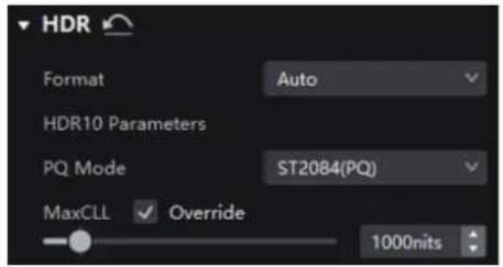
HDR10 parameters:
- PQ Mode: The mapping method of video source brightness.
- ST2084 (PQ): This mode 1:1 maps the brightness of the video source. The part that exceeds the maximum screen brightness will still be displayed as the maximum screen brightness.
- ST2086 (Linear mapping): This mode linearly maps the brightness of the video source. It globally adjust the video source brightness according to the maximum screen brightness to ensure that the ratio of the brightness of the entire source content remains unchanged.
- MaxCLL: The override value of the maximum video source brightness. MaxCLL takes effect when Override is selected.
4.5.3 Set Internal Sources
The internal sources can be used for screen testing and troubleshooting. Select the controller from the device list and then select Source. Select an internal source from the source list and do the following as required.
Set the Image
Select an image and set the Grayscale, Gradient Stretch, Speed, and Space. The adjustable parameters for each image may vary based on the interface.
- Static images

• Dynamic images

Set the Resolution, Refresh Rate, and Bit Depth
Select a value from the drop-down lists of Resolution, Refresh Rate, and Bit Depth and then click Apply.
Figure 4-23 Internal source parameters

4.6 Display Correction
4.6.1 Correct Seams
Adjust brightness of the seams between cabinets or modules to improve the visual experience. If brightness correction has been done for the screen, the screen brightness can be adjusted in nits. Otherwise, it can be adjusted only in percentage.
Step 1 Select the controller from the device list and then select Correction.
Step 2 On the Seams tab page in the properties area, set the Seam Correction switch to

Step 3 Set the parameters in the Display area.
Figure 4-24 Display content (seams)
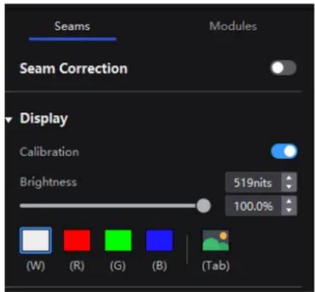
- Calibration: Set the Calibration switch to 📋 to make the screen apply the calibration effect made by the calibration platform.
● Brightness: Adjust the display brightness. - Image: Set which image the screen displays. To display the image of current input source, click and hold it.
Step 4 Select a correction mode.
Figure 4-25 Select mode (seams)

• Cabinet Seams: Correct the seams of cabinets.
• LDM Seams: Correct the seams of the modules.
Step 5 When correcting the module seams, if you need to override the numbers of module columns and rows, set the Cabinet Structure Override switch to . Otherwise, skip this step.
Figure 4-26 Cabinet structure override

Step 6 In the topology area, click or click and drag the mouse to select the seams to be corrected.
Step 7 Set the adjustment parameters.
Figure 4-27 Set the parameters.

- Quick adjust: Has a large range of adjustment.
● Fine adjust: Has a small range of adjustment. - Hide cursor on screen: When this is set to , use the keyboard shortcuts to adjust the seams and the cursor will not be displayed on the screen.
Step 8 Place the mouse on the scroll wheel icon and adjust the brightness by dragging the wheel icon up or down, scrolling the mouse wheel, or using the keyboard shortcuts 4+/ .
- Restore: Restore the configuration to the last saved.
- Reset: Reset the configuration to the status before adjustment.
Step 9 After the settings, click Save.
4.6.2 Correct Multi-Batch Cabinets/Modules
Adjust the chroma of cabinets or modules from multiple batches to make the overall chroma of the display more balanced and uniform. If brightness correction has been done for the screen, the screen brightness can be adjusted in nits. Otherwise, it can be adjusted only in percentage.
Step 1 Select the controller from the device list and then select Correction.
Step 2 Select the Modules tab in the properties pane.
Step 3 Set the display content.
Figure 4-28 Display content (multiple-batch)

- Calibration: Set the Calibration switch to ☐ to make the screen apply the calibration effect made by the calibration platform.
● Brightness: Adjust the display brightness.
• Image: Set which image the screen displays. To display the image of current input source, click and hold it.
Step 4 Select a correction mode.
Figure 4-29 Select mode (multiple-batch)

• Cabinet: Correct the multi-batch cabinets.
- Module: Correct the multi-batch modules.
Step 5 When correcting the multi-batch modules, if you need to overwrite the numbers of module columns and rows, set the Cabinet Structure Override switch to . Otherwise, skip this step.
Figure 4-30 Cabinet structure override

Step 6 In the topology area, click or click and drag the mouse to select the cabinets or modules to be corrected.
Step 7 Drag the slider to adjust chroma.
Figure 4-31 Adjustment

- Restore: Restore the configuration to the last saved.
- Hide cursor on screen: When this is set to , use the keyboard shortcuts to adjust chroma and the cursor will not be displayed on the screen.
Step 8 After the settings, click Save.
4.6.3 Lock and Unlock Correction Page
After the screen correction is finished, you can lock the Correction page by either of the following methods to avoid changing the display content due to misoperation.
- Right-click the Correction icon and click Lock. Clicking Lock again unlocks the page.
- From the menu bar, choose View > Lock Correction. Clicking Lock Correction again unlocks the page.
Figure 4-32 Correction icon

Note
After the Correction page is locked and you have entered another page, if you want to go back to the Correction page, you must manually unlock the page first.
4.7 Color Processing
4.7.1 Color Replacement
Replace a color with another color according to the settings.
Notice
It is recommended to choose color with higher saturation for replacement to achieve better outcome.
Operating Procedure
Step 1 Select the controller from the device list and then select Processing.
Figure 4-33 Color Processing

Step 2 Set the Color Replacement switch to .
Step 3 Set the colors before and after replacement.
- Method 1: Click the color area in to open the color palette and set a color.
• Method 2: Click the eyedropper in and select a color in the topology area.
Figure 4-34 Color Replacement
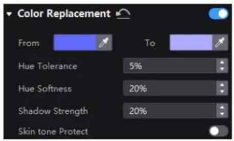
Step 4 Set Hue Tolerance, Hue Softness, Shadow Strength, and Skin Tone Protect.
- Hue Tolerance: Indicates the hue range of the color to be replaced. The larger the value, the larger the replacement area
- Hue Softness: Indicates the hue softness of the transition area.
- Shadow Strength: Indicates the gradient parameter of the highlight or shadow area. The larger the value, the smoother the gradient.
- Skin Tone Protect: Keeps the skin tone as original as possible.
4.7.2 14Ch Color Correction
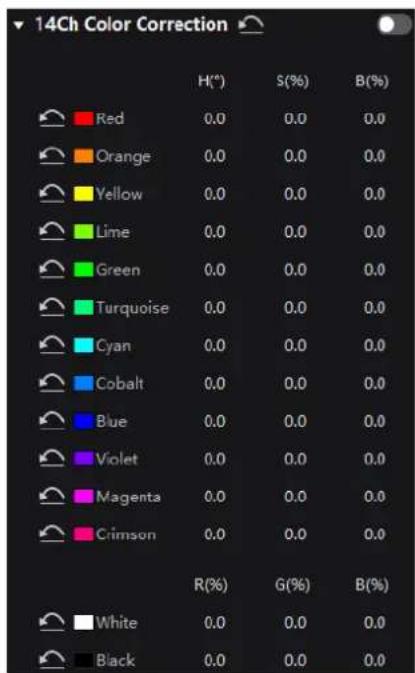
Precisely adjust the hue, saturation and brightness of black, white, and the 12 derived standard colors of the red, green and blue primary colors.
Step 1 Select the controller from the device list and then select Processing.
Step 2 Set the 14h Color Correction to .
Step 3 Click a value of a color to enable the editing and change the value, , for example.
Figure 4-35 14CH Color Correction
4.7.3 Set Color Curves
Adjust the color curves.
Step 1 Select the controller from the device list and then select Processing.
Step 2 Set the Curves switch to .
Figure 4-36 Curves

Step 3 Select the white, red, green or blue channel.
Step 4 Drag the slider at the bottom of the curve diagram to set the curve adjustment range.
Step 5 Click anywhere on the curve to add an adjustment point and drag the point to adjust the curve.
Input and Output indicate the absolute coordinates of the adjustment point in the curve diagram.
To delete the adjustment point, drag the point outside the curve diagram, or select the point and press Delete.
Click the 📄 icon at the right of Channel to reset the curve of the current channel. Click the 📄 icon next to Curves to reset all the curves.
4.7.4 Enable 3D LUT
A set of mapping relationships are defined in the 3D LUT file (.cube) to adjust the colors of the video source.
Prerequisites
A 17×17×17 3D LUT file must be prepared in advance.
Operating Procedure
Step 1 Select the controller from the device list and then select Processing.
Step 2 Click anywhere in the Load 3DLUT File area, select a file and open it.
Figure 4-37 Loading 3D LUT file
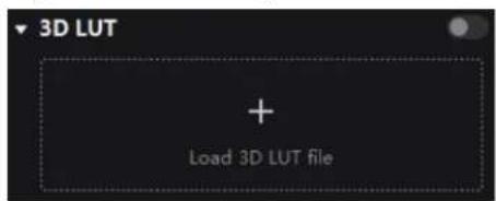
Step 3 Set the 3D LUT to and drag the slider to adjust the strength of the 3D LUT.
Figure 4-38 Adjusting intensity

To delete the file, click

4.8 Screen Settings
4.8.1 Adjust Image Quality
4.8.1.1 Adjust Brightness and Gamma
If brightness correction has been done for the screen, the screen brightness can be adjusted in nits. Otherwise, it can be adjusted only in percentage.
Step 1 Select the controller from the device list and then select Screen Settings.
Figure 4-39 Screen Settings

Step 2 In the Image Quality tab, set the brightness and gamma value.
Figure 4-40 Brightness and gamma adjustments

4.8.1.2 Set LED Image Booster
Set the LED Image Booster function to improve the precision and accuracy of the image color and gradation and realize free switching of the display color gamut.
Prerequisites
Before the operation, color gamut and brightness correction by using the CA410-VP427, CA410-P427 or EYE2-400 color analyzer must be done.
Operating Procedure
Step 1 Select the controller from the device list and then select Screen Settings.
Step 2 In the LED Image Booster section of the Image Quality tab, select an output color gamut from the Gamut drop-down list.
The output gamut options include standard gamuts, custom gamuts, the original screen gamut and the input gamut (From input).
To set the custom gamut, click a select a gamut in the properties area on the color gamut diagram, and adjust the red, green, blue and white parameters based on the selected gamut. The custom gamut name can be changed.
Step 3 Drag the slider to adjust color temperature.
Step 4 Enable or disable Magic Gray as needed.
Figure 4-41 LED Image Booster

4.8.1.3 Apply Calibration Effect
Check the effects before and after screen calibration.
Prerequisites
Before operation, screen calibration must be done and calibration coefficients must be uploaded.
Related Information
When the A10s Pro receiving card is used, the seam correction can be performed separately. This means even if the calibration switch is turned off, the seam correction effect is still kept.
Operating Procedure
Step 1 Select the controller from the device list and then select Screen Settings.
Step 2 In the Image Quality tab, set the Calibration switch to to make the screen apply the calibration effect made by the calibration platform.
Figure 4-42 Calibration

4.8.1.4 Set Thermal Compensation
Adjust the application intensity of the thermal coefficients.
Prerequisites
Before the operation, thermal calibration must be done and thermal coefficients must be uploaded.
Operating Procedure
Step 1 Select the controller from the device list and then select Screen Settings.
Step 2 In the Image Quality tab, set the Thermal Compensation switch to .
Figure 4-43 Thermal compensation
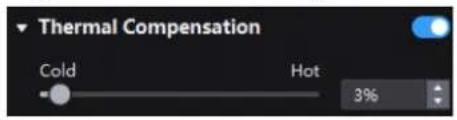
Step 3 Drag the slider to adjust the application intensity of the thermal coefficients.
4.8.1.5 Adjust EOTF

The supported adjustment parameters depend on the HDR settings.
Step 1 Select the controller from the device list and then select Screen Settings.
Step 2 In the Image Quality tab, drag the sliders to adjust the values of Shadow Compensation, Ambient Light Compensation and Clip Level.
Figure 4-44 EOTF Adjustment

4.8.2 Set Output
4.8.2.1 Set Output Bit Depth and Additional Frame Latency

When the controller works with high-latency devices, you can set additional frame latency.
Step 1 Select the controller from the device list and then select Screen Settings.
Step 2 In the Output tab, select an option from the drop-down list of Bit Depth.
If Auto is selected, the output bit depth is the same as the input bit depth.
Figure 4-45 Output bit depth
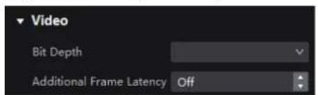
Step 3 Set a value for Additional Frame Latency.
4.8.2.2 Set Sync Parameters
Step 1 Select the controller from the device list and then select Screen Settings.
Step 2 Select the Output tab.
Step 3 Select a synchronization signal for the display frame rate and set the phase offset.
Figure 4-46 Sync

• Active Source: Sync with the frame rate of the active source.
- Genlock: Sync with the frame rate of the Genlock signal. When the shutter fit function of the controller is effective, please select this option. In addition, the controller and the camera need to use the same Genlock signal generator.
- Internal: Sync with the frame rate of the controller's internal clock.
4.8.2.3 Set Frame Multiplication
Frame multiplication can make the screen output multiple frames within the original one frame time and provide them to different cameras.
Notice
- When the A10s Pro, CA50E, CA50C, or XA50 receiving cards are used, the supported frames rate is up to 240 Hz.
- For other Armor series receiving cards, the supported frame rate is up to 120 Hz.
Operating Procedure
Step 1 Select the controller from the device list and then select Screen Settings.
Step 2 In the Output tab, set Frame Multiplication to .
Figure 4-47 Frame Multiplication

Step 3 Set the number of frames and the display mode of each frame.
Take the above Figure 4-47 as an example. The parameters are described as follows:
- Frame Multiplication: After the current frame rate (59.94) is multiplied by 3, it is 179.82 Hz. Three frames are output in 1/59.94 second.
- Video: The first and second frames display the input source image. The first frame displays the image from the coordinates (0, 0) and the second frame displays the image from the coordinates (1920, 0).
• Color: The third frame displays a pure white image.
4.8.2.4 Set Shutter Fit
Adapt the screen and camera shutter to produce better filming results.
Prerequisites
It requires that the sync signal must be Genlock and the controller and camera need to use the same Genlock signal generator.
Operating Procedure
Step 1 Select the controller from the device list and then select Screen Settings.
Step 2 In the Output tab, set Shutter Fit to .
Figure 4-48 Shutter Fit
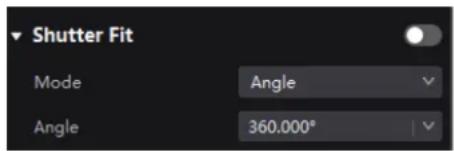
Step 3 Set the relevant parameters.
4.8.2.5 Enable 3D Function
Enable the 3D function and set the related parameters for users wearing 3D glasses to view stereoscopic images.
Notice
● The 3D function and the low latency or frame multiplication function cannot be enabled at the same time.
• Only the main layer supports 3D effect.
Related Information
To use the 3D function, specified 3D glasses are needed. Please contact NovaStar technical support.
Operating Procedure
Step 1 Select the controller from the device list and then select Screen Settings.
Step 2 In the Output tab, set 3D to .
Figure 4-49 3D

Step 3 Set the relevant parameters.
- Source Format: Set the format of the 3D video source. Set the format to Side-by-side, Top-and-bottom or Frame sequential according to the format of the accessed video source.
- Right Eye Offset: Set the start position of the right eye image. When the video source format is side-by-side or top-and-bottom and the left and right eye images are provided, this parameter can be set.
- Eye Priority: Set which image is sent first, the right eye image or the left eye image. Wear the 3D glasses to watch the display. If the display is abnormal, set the parameter value to the other one. If the display is normal, the setting is done.
- 3rd Emitter: When a third-party 3D signal emitter is used, set the switch to
- Emitter Delay: Set the delay time of sending the synchronization signal from the 3D signal emitter to the 3D glasses. This setting ensures that the switching between left and right eye images of the 3D glasses is in sync with the switching between the left and right eye images on the display. This parameter is applicable to both the NovaStar and third-party emitters.

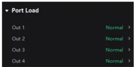
4.8.2.6 Check the Load
Step 1 Select the controller from the device list and then select Screen Settings.
Step 2 In the Output tab, click ➤ next to the device information to check the usage of the controller's load capacity.
Figure 4-50 Port load
4.9 Preset Management
4.9.1 Save Presets
After completing the display effect adjustment, you can save the data of the Source, Layout, Processing and Screen Settings pages as presets so that these data can be directly applied in the future. Up to 128 presets can be saved in VMP.
Notice
The preset of a specific device can only be applied by this device itself and the preset of a group can be applied by all the devices in the group.
Operating Procedure
Step 1 Select the controller from the device list and then select Preset.
Step 2 On the preset management page, click to enter the page shown in Figure 4-51.
To go back to the preset management page, click a blank area in the properties area.
Figure 4-51 Preset management
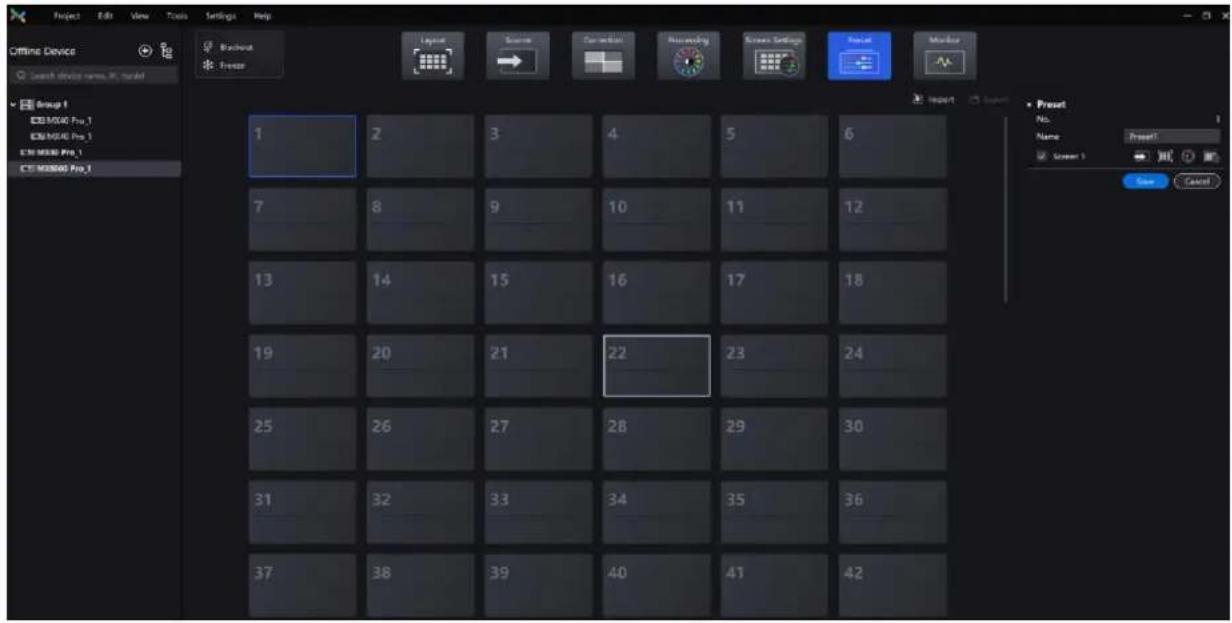
Step 3 Click the icon of a preset.
Step 4 In the properties area, set a name for the preset and select the screen and data you need to save.
If the preset you selected is not empty, the original data will be overwritten.
Step 5 Click Save.
4.9.2 Apply Presets
Apply a saved preset to quickly complete settings of the parameters on the Source, Layout, Processing and Screen Settings pages.
Notice
The preset of a specific device can only be applied by this device itself and the preset of a group can be applied by all the devices in the group.
Operating Procedure
Step 1 Select the controller from the device list and then select Preset.
Step 2 On the preset management page, double-click a preset and wait it to finish loading.
The preset that is being used has a ▼ at the top right.
Figure 4-52 Apply presets

4.9.3 Manage Presets
Select the controller from the device list and then select Preset and do the following operations as needed.
Modify a Preset
Select a preset. In the properties area, change the related information and click Save.
Delete a Preset
- Right-click a preset and select Delete from the pop-up menu.
- On the preset management page, select a preset and click Delete in the properties area.
Clear Presets
Right-click a preset and select Delete All from the pop-up menu.
4.9.4 Import and Export Presets
Select the controller from the device list and then select Preset and do the following operations as needed.
Import Presets
Click Import, select a preset file (.nprt) and click Open. In the displayed dialog box, select the device to which you want to import the file and click OK.
Figure 4-53 Import presets

Export Presets
Click Export, select a file page, set a file name, and click Save.
4.10 Screen Monitoring
4.10.1 Check Device Status
Select the controller from the device list and then select Monitor. Click the function icons on the left to check the related information
Figure 4-54 Screen monitoring
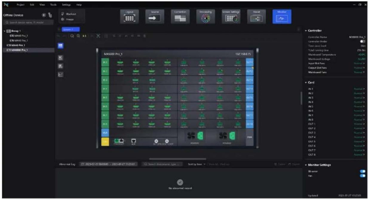
• : The controller.
- Check the status of the connectors on the rear panel of the controller.
- Check the controller's name, current uptime, total uptime, mainboard temperature, mainboard voltage, and fan status.
- Check the temperature and voltage of the cards.
- Set on/off of the Controller Finder switch. When set to 📄, you can locate the controller.
- Set on/off of the Total Errors switch. When set to 📄, you can monitor the errors.
- Set on/off of the Fan switch. When set to 📄, you can monitor the fan status and display it in the Controller area.

• The receiving card temperature. In the properties area, you can check the temperature information.

• : The cabinet voltage. In the properties area, you can check the voltage information.

- The total bit errors. In the properties area, you can check the detailed information of the errors. Click to clear the errors and click to check the error information in a specified time range.

Note
Selecting 📄, 📄, or 📄 enables you to check the cabinet position, voltage, total uptime, and current uptime under the Cabinet section of the properties area. You can also blackout, freeze, or enable test patterns for cabinets under the Cabinet Settings section.
4.10.2 Check Monitoring Records
Select the controller from the device list and then select Preset. At the bottom of the page, do the operation as needed.
Figure 4-55 Monitoring records

Search records
Enter the key words in the search box.
Query records
Click the time widget and set the start and end time. If you select Now, the monitoring records will be updated in real time.
Set how the records are displayed
From the drop-down list, select Sort by time, Order by controller, Order by type, and Order by level. If the latter three are selected, the records can be expanded or collapsed.
Clear records
Click Delete and then click OK.
Export records
Click Export, select a file page, set a file name, and click Save.
4.11 Calibration Coefficient Management
Upload, save, adjust, and read back calibration coefficients.
4.11.1 Upload Calibration Coefficients
Upload the local calibration coefficient file to the current screen, cabinet or module and apply the coefficients to the display effect.
Prerequisites
• To upload screen coefficients, make sure:
- The screen configuration is done, the cabinets are not rotated, and there are no cabinet gaps or overlapping.
- The configured screen must be rectangular, and the cabinet on the top left corner (as shown in the figure below) must be at the (0, 0) point of the canvas.

natural_image
Colorful spiky pencil arrangement radiating from a central point, displayed within a software interface window (no text or symbols on the pencils themselves)- To use the database file, you should prepare it in advance, and the resolutions of the configured screen and the screen in the database must be the same.
• To upload cabinet coefficients, make sure:
The target cabinets must have cabinet IDs.
Notice
During coefficient uploading, if the controller and/or receiving cards go offline, the uploading will fail.
If the coefficient uploading fails, the coefficients will not be saved automatically. You can manually save them as needed.
Operating Procedure
Step 1 In the device list on the left, select the desired controller.
Step 2 From the menu bar, choose Tools > Coefficient Management.
Figure 4-56 Calibration coefficient management

Step 3 In the Select Mode area, select the uploading range. The options include Screen, Cabinet and LDM.
Figure 4-57 Select mode

Step 4 In the Coefficient Management area, click + and select the target calibration data file (.db) from the local computer.
The coefficient types in the file will be read automatically. You can select the range of coefficient types as needed.
Figure 4-58 Upload calibration coefficients
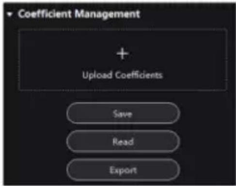
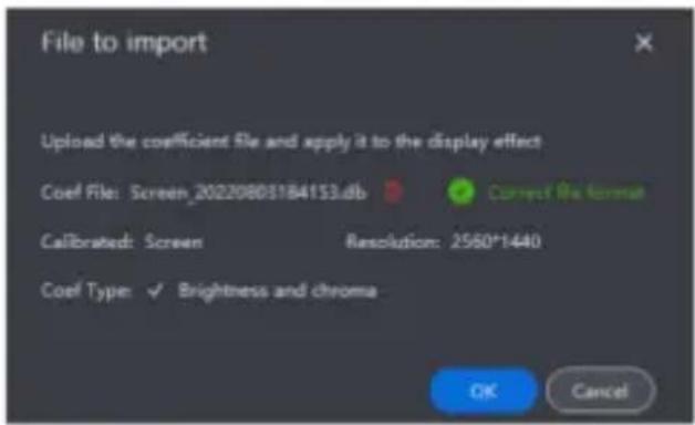
Step 5 Click OK to upload the coefficients to receiving cards.
4.11.2 Edit Calibration Coefficients
Prerequisites
• Calibration coefficients are available.
• Cabinet configuration is done and the cabinets stay online.
Operating Procedure
Step 1 In the device list on the left, select the desired controller.
Step 2 From the menu bar, choose Tools > Coefficient Management.
Step 3 In the Select Mode area, select Pixel.
Figure 4-59 Select mode

Step 4 In the topology, click to select a cabinet.
Step 5 In the displayed window, select the target pixels and enter the parameters in the Coefficient Management area to adjust the proportion relationship of the red components, green components and blue components in RGB.
The calibration coefficients of the selected pixels will be overridden and changed to the values you set.
Figure 4-60 Pixel calibration coefficients

Table 4-2 Table 12-1 Parameter relationship and value range
| / | Red-R | Green-G | Blue-B |
| Red-R | RR (512 ~ 2047) | GR (0 ~ 255) | BR (0 ~ 127) |
| Green-G | RG (0 ~ 255) | GG (512 ~ 2047) | BG (0 ~ 255) |
| Blue-B | RB (0 ~ 127) | GB (0 ~ 127) | BB (512 ~ 2047) |
Table 4-3 Icon description
| Icon | Description |
 | The step of single increase or decrease. Use it together with [IMAGE] |
 | Increase or decrease the coefficient value of the selected pixel. |
| Click to close the pixel topology. |
4.11.3 12.3 View Calibration Effect
Notice
If brightness correction has been done for the screen, the screen brightness can be adjusted in nits. Otherwise, it can be adjusted only in percentage.
Set the Display Content
In the Display area, you can adjust the screen brightness to clearly see the actual calibration effect change at each grayscale. You can also switch the color to see the uniformity of a single color and the entire display image.
Figure 4-61 Set display content

● Brightness: Adjust the screen brightness.
- Display image: Set the image displayed on the screen. To display the current source image, click and hold
- Show locating cursor: When the switch is set to , the selected area on the screen will display blue borders. This helps you quickly locate the cabinets, modules or pixels that you are currently operating.
Enable and Disable Calibration Effect
In the Calibration area, you can turn on or off the sub-calibration switches and then view the display effects before and after the calibration.
The sub-calibration switches include Brightness and Chroma Calibration, Full-Grayscale Calibration and Low-Grayscale Calibration. The actual displayed switches depend on the existing coefficient types of the screen.
Figure 4-62 Sub-calibration switches

The main calibration switches are on the Correction and Screen Settings pages. When the main calibration switches are turned on or off, all the sub-calibration switches will be turned on or off simultaneously.
Figure 4-63 Main calibration switches


4.11.4 Save Calibration Coefficients
Notice
During coefficient saving, if the receiving cards go offline, the saving will fail.
Operating Procedure
Save the calibration coefficients of the current screen, cabinet or module to the receiving card to avoid calibration effect loss due to power failure.
Step 1 In the device list on the left, select the desired controller.
Step 2 From the menu bar, choose Tools > Coefficient Management.
Step 3 In the Select Mode area, select the saving range as needed, including Screen, Cabinet, LDM and Pixel.
Figure 4-64 Select mode

Step 4 In the Coefficient Management area, click Save.
Figure 4-65 Save calibration coefficients
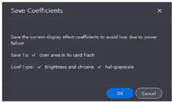
Step 5 In the pop-up dialog box, set the relevant parameters and click OK to save the current coefficients to the receiving cards.
4.11.5 Read Back Calibration Coefficients
Read back the calibration coefficients saved in the receiving card and apply them to the current screen.
Notice
During coefficient readback, if the receiving cards go offline, the readback will fail.
Operating Procedure
Step 1 In the device list on the left, select the desired controller.
Step 2 From the menu bar, choose Tools > Coefficient Management.
Step 3 In the Select Mode area, select the reading range as needed, including Screen, Cabinet, LDM and Pixel
Figure 4-66 Selecting working mode
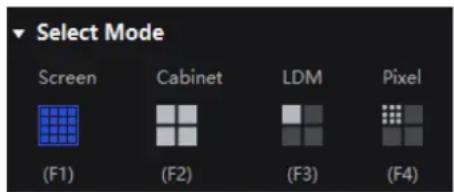
Step 4 In the Coefficient Management area, click Read.
Figure 4-67 Read back coefficients

Step 5 In the pop-up dialog box, set the relevant parameters and click OK to read the coefficients and apply them to the screen.
4.11.6 Export Calibration Coefficients
Export the calibration coefficients of the current screen, cabinet or module to the local computer. When the receiving card is replaced or the new screen has the same specifications, you can upload the exported calibration coefficients directly to use.
Prerequisites
• To export screen coefficients, make sure:
- The screen configuration is done, the cabinets are not rotated, and there are no cabinet gaps or overlapping.
- The configured screen must be rectangular, and the top-left-corner coordinates of the circumscribed rectangle of the configured screen must be (0, 0).
• To export cabinet coefficients, make sure:
The target cabinets must have cabinet IDs.
Notice
During coefficient exporting, if the controller and/or receiving cards go offline, the exporting will fail.
Operating Procedure
Step 1 In the device list on the left, select the desired controller.
Step 2 From the menu bar, choose Tools > Coefficient Management.
Step 3 In the Select Mode area, select the export range as needed, including Screen, Cabinet, LDM and Pixel.
Figure 4-68 Select mode

Step 4 In the Coefficient Management area, click Export.
Step 5 Select a file path on the pop-up dialog box and click Save.
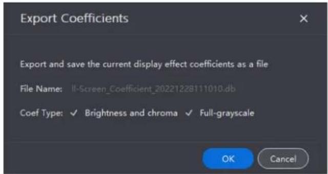
Step 6 In the pop-up Export Coefficients window, set the relevant parameters and click OK to export the coefficients of the screen to a file (.db).
Figure 4-69 Export coefficients
4.12 Screen Maintenance
4.12.1 Maintain Controllers
From the menu bar, choose Tools > Maintain and do the following operations as needed.
Figure 4-70 Controller maintenance

Operations in Device List
In the device list, right-click a controller. In the pop-up menu, select Controller Properties to open its dialog box.
Figure 4-71 Controller properties

Check the device Information
Check the basic information, detailed information, input card information and output card information of the controller.
+ Change the time
Click the time widget and change the time.
+ Change the time zone
Select a time zone from the Time zone drop-down list.
Export Logs
Click Export Log, select a location, set the file name, and click Save.
After you right click a controller in the device list, you can also perform the following operations:
+ Rename the controller
In the pop-up menu, select Rename and rename the controller.
Enabling Mapping
In the pop-up menu, select Mapping to enable the Mapping function. It allows users to easily obtain the locations and connection topology of receiving cards.
Operations on Controller Maintenance Page
In the device list on the left, select a controller or a group. On the Controller page, select the target controllers and then perform the operations.
Find the controller
Click Controller Finder to mark the area loaded by the controller on the LED screen and the LCD screen of the controller becomes green, which helps you find the controller quickly.
Upgrade the firmware program
Click Upgrade, select the firmware program file (.img) or .zip file and click Open. On the displayed window, double-check the uploaded file name and version and click Update to start upgrading.

Note
All cards must be updated at the same time.
During the upgrade process, the controller will automatically restart. In addition, please do not close VMP or switch to another controller until the upgrade is complete.
+ Restart the controller
Click Restart and click OK.
+ Reset settings (operate with caution)
Click Reset and click OK.
4.12.2 Maintain Cabinets
Related Information
For the cabinet painter operation, the configuration parameters of the cabinet to be copied can be saved to local computer as an .rpkg file for future use.
Operating Procedure
From the menu bar, choose Tools > Maintain and select the Cabinet tab. In the device list, select the target controllers and perform the following operations on the cabinets as needed.
Figure 4-72 Cabinet maintenance

Select the target cabinets and perform any of the following operations :
- Check the cabinet information
Check the cabinet status, manufacturer, model, firmware version, location, etc.
Copy the firmware program and configuration file
Click Cabinet Painter and select one or more cabinets so that other cabinets can have the same firmware program and configuration file as the selected cabinet. - Restart the cabinet
Click Restart and click OK.
To upload image quality file, select Image Quality File.
c. Select the target row of cabinet data and click Update.
d. After the file is uploaded, click Save Rv-card config.
+ Refresh information
Click Refresh.
Find the cabinet
Click Cabinet Finder in the Action column. This function helps you find the cabinet on the screen quickly.
4.13 Software Settings
4.13.1 Offline Mode
You can add offline devices without connecting to a device to perform operations in VMP.
Step 1 From the menu bar, choose Tools > Offline Mode > Enter Offline Mode.
Step 2 Click on the top of the device list.
Step 3 Click Add Controller in the pop-up dialog box.
To add multiple devices of the same model, click Batch Add.
Figure 4-73 Add controller
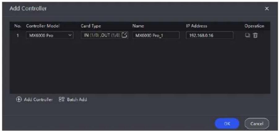
Step 4 Select MX6000 Pro from the drop-down list of Controller Model.
Step 5 Click 📋 and then select input and output cards in the pop-up window. Click OK once you are done.
Figure 4-74 Edit cards

Step 6 Fill in the IP address and controller name.
Step 7 Click OK once you are done.
Click to copy the current device and click to delete it.
4.13.2 14.1 Change Language and Temperature Scale
From the menu bar, choose Settings > General, select the target language and temperature scale, and click OK.
Figure 4-75 Changing the display language

4.13.3 Manage Cabinet Library
From the menu bar, choose Settings > Cabinet Library. Click Manage Packs and do the following operations as needed to manage the cabinet library files.
Figure 4-76 Cabinet library

Upload NCP File
Step 1 Click Add. On the displayed window, click Upload File.
Figure 4-77 Adding NCP file

Step 2 Select the targets to be imported (multiple targets can be selected).
- When Local pack is selected, the imported NCP file will be saved under the VMP installation directory.
- When Device pack is selected, the imported NCP file will be saved in the LED controller's storage space.
Step 3 Select the .ncp file to be imported from the local computer and click Add.
After the file is selected, you can click Delete to delete the uploaded file.
You can also click Refresh to refresh the NCP file list.
Export NCP File
Step 1 Select one or more files on the Manage Packs screen and then click Export.
For batch export, multiple files will be compressed as a .zip file and exported.
Step 2 Select a local directory and click Save.
Figure 4-78 Successful export

Sync NCP File
- Sync NCP files between the device and local computer
Select the files to be synced (multiple files can be selected), and click

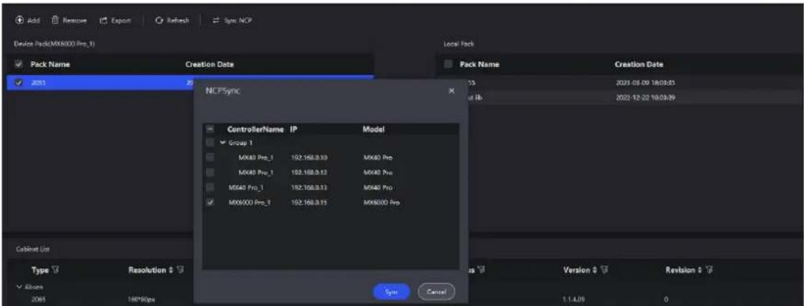
- Sync NCP files between devices
a. Select the files to be synced (multiple files can be selected), and click Sync NCP.
b. On the displayed window, select the devices to which the files are synced (multiple devices can be selected).
c. Click Sync.
Check NCP File Information
Select an NCP file, and the information about all the cabinets that use this NCP file will be displayed in the Cabinet List area below. The information includes cabinet type, resolution, maximum frame rate, receiving card type, release status, version and revision.
Figure 4-79 NCP file information

4.13.4 14.3 Check User Manual
From the menu bar, choose Help > User Manual to open and check the VMP user manual.
4.13.5 14.4 Check Software Information
From the menu bar, choose Help > About and check the software information.
4.13.6 Check Keyboard Shortcuts
From the menu bar, choose Help > Keyboard Shortcuts and check the commonly used software operation shortcuts.
5 Front Screen Panel
5.1 UI Introduction
5.1.1 Home Screen
After the device is powered on, the home screen showing device related information is displayed as Figure 5-1. Rotate the knob to select an input or output card to view its details, as shown in Figure 5-2.
Figure 5-1 Home screen

Figure 5-2 Input and output card details

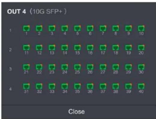
The home screen is shown in Figure 5-1 and the home screen descriptions are shown in Table 5-1.
Table 5-1 Home screen descriptions
| Area | Content | Description |
| Top line | MX6000 Pro | The device name.The name can be changed in VMP software. |
| The device button and touchscreen lock status.When the icon is displayed: The buttons are locked.When the icon is not displayed: The buttons are unlockedHold down the knob and BACK button simultaneously for 5s or longer to lock or unlock the buttons and screen. | ||
| [STOS] | The connection status of the USB driveGreen: ConnectedWhen the icon is not displayed: Disconnected | |
| 192.168.102.189 | The device IP address | |
| Input / Output | IN 1 to 8 | The device input source type and status.Green: The input source is connected.Red: The input source is being used for the screen but not connected.Gray: The input source is not connected. |
| OUT 1 to 8 | The status of the output Ethernet ports.Green: The Ethernet port is connected and working normally.Red: The Ethernet port is connected but working abnormally.Gray: DisconnectedWhen the Ethernet port, associated card, or associated device is used as a backup, you will see an orange triangular icon displayed in the top-right corner. | |
| MVR (Reserved) | The status of the MVR card ports. | |
| Control | CTRL | The status of the control Ethernet port, AUX port, and GENLOCK port.Green: ConnectedGray: Disconnected |
| Power Supply | PWR | The status of the device power supply.Green: ConnectedGray: Disconnected |
| Bottom line | [EXX86] | The chassis fan speed.Green: The fan speed is normal.Yellow: Fan speed alarm. The speed has exceeded the threshold range.Yellow: Fan speed alarm. The speed has exceeded the threshold range significantly. |
| [EXXOW] | The supply voltage of the mainboard.Meaning of numerical colors:Green: The voltage is normal.Yellow: Voltage alarm. The voltage has exceeded the threshold range.Red: Voltage alarm. The voltage has exceeded the threshold range significantly. | |
| [TSX4] | The temperature inside the chassisMeaning of numerical colors:Green: The temperature is normal.Yellow: Temperature alarm. The temperature has exceeded the threshold range.Red: Temperature alarm. The temperature has exceeded the threshold range significantly. | |
| Right | Genlock | The sync signal currently used. |
| side | Screens | The number of screens with load. |
| Blackout | The number of screens that are blacked out. | |
| Frozen | The number of screens that are frozen. | |
| Menu | The device main menu. |
5.1.2 Main menu
On the home screen, tap the menu icon at the bottom right or press the knob to enter the main menu page.
Figure 5-3 Main menu

Table 5-2 Main menu descriptions
| Module | Description |
 | Show screen name, sync signal source, and brightness. Set brightness, color temperature, gamma, as well as enable black screen or freeze screen. |
 | Set internal source, check external input source information, and configure EDID and HDR parameters for external input sources. |
 | Configure network parameters. |
 | Set LCD screen timeout and brightness, set system language and temperature scale, chec firmware information, and restore factory settings. |
 | Perform device diagnostics, view and export logs, and check device status. |
5.2 Screen
5.2.1 Set Brightness, Color Temperature and Gamma
Step 1 Select Screen from the main menu to access the screen list.
The list displays screen names, sync signal sources, and brightness.
Step 2 Select a screen to open the parameter settings.
Figure 5-4 Set Brightness, color temperature and gamma

Step 3 Adjust the values for brightness, color temperature and gamma.
5.2.2 Set Screen Status
Step 1 Select Screen from the main menu to access the screen list.
The list displays screen names, sync signal sources, and brightness.
Step 2 Select a screen to open the parameter settings.
Figure 5-5 Set screen status

Step 3 Select Blackout or Freeze and then press the knob to toggle on or off the switch.
●: Enabled. The screen display will turn black or freeze, but the playback will not be interrupted.
5.3 Input
5.3.1 Set Internal Source
Step 1 Select Input from the main menu to access the input source list.
Step 2 Select Internal source to open the parameter settings.
Figure 5-6 Input source
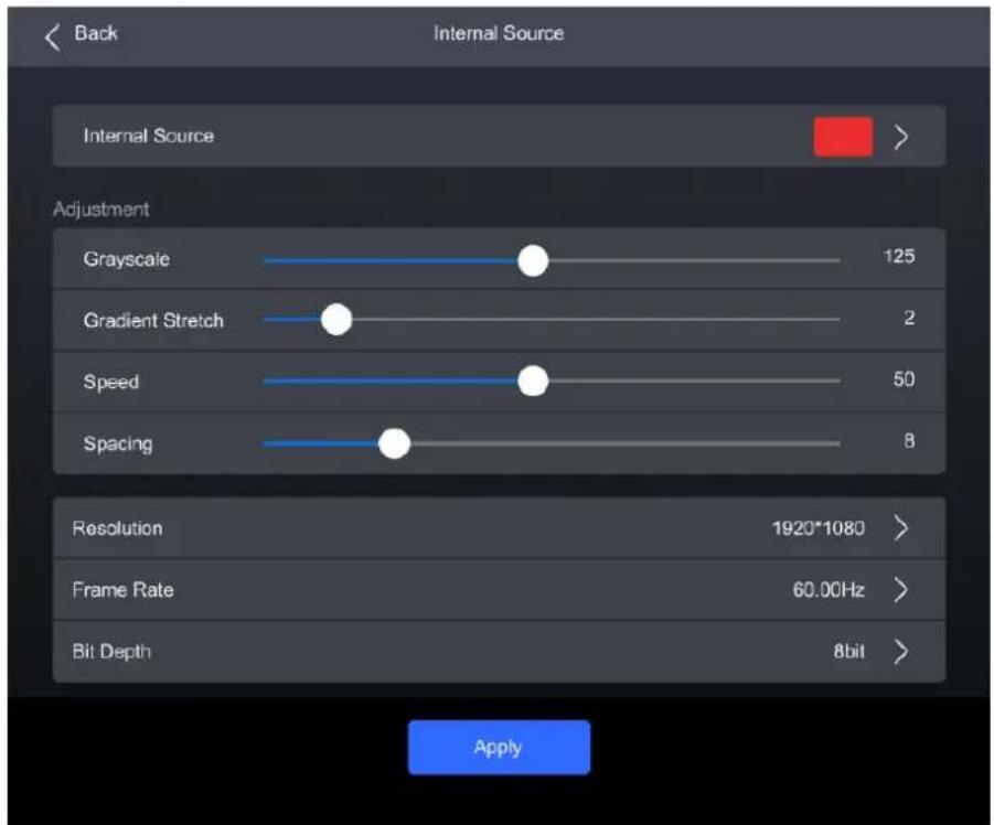
Step 3 Select Internal Source, navigate to the sub-interface, and then select an image.
Step 4 Press BACK to return to the parameter settings.
Step 5 Set the Grayscale, Gradient Stretch, Speed, and Space. The adjustable parameters for each image may vary based on the interface.
Step 6 Select Resolution, Frame Rate, and Bit Depth in sequence and set a value for each in the pop-up dialog box.
Step 7 After the settings are done, click Apply.
5.3.2 Check Input Source Information
Step 1 Select Input from the main menu to access the input source list.
Step 2 Select an input source to access the Information tab.
Figure 5-7 Input source information

Step 3 Check the input source information.
5.3.3 Set EDID
Step 1 Select Input from the main menu to access the input source list.
Step 2 Select an input source to open the parameter settings.
Step 3 Navigate to the EDID tab.
Figure 5-8 EDID

Step 4 Select Resolution and Frame Rate in sequence and set a value for each in the pop-up dialog box.
Step 5 After the settings are done, click Apply.
5.3.4 Set HDR
Step 1 Select Input from the main menu to access the input source list.
Step 2 Select an input source to open the parameter settings.
Step 3 Navigate to the HDR10 tab.
Figure 5-9 HDR10
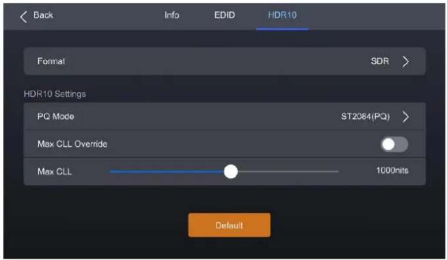
Step 4 Select Format and then select Auto, HDR10, HLG, or Close from the pop-up dialog box.
Step 5 For HDR10, please set the relevant parameters.
- PQ Mode: The mapping method of video source brightness.
ST2084 (PQ): This mode 1:1 maps the brightness of the video source. The part that exceeds the maximum screen brightness will still be displayed as the maximum brightness.
ST2086 (Linear mapping): This mode linearly maps the brightness of the video source. It globally adjust the video source brightness according to the maximum screen brightness to ensure that the ratio of the brightness of the entire source content remains unchanged.
• Max CLL Override: Enable or disable Max CLL override.
• Max CLL: The max content light level.
5.4 Communication
Step 1 Select Communication from the main menu to access the settings interface.
Figure 5-10 Network

Step 2 Toggle on or off Obtain Automatically.
• The device automatically obtain an IP address.
• : You need to manually set an IP address for the device.
Step 3 If Obtain Automatically is disabled, you need to set an IP Address, Subnet Mask and Default Gateway and. If it is enabled, this step is not required.
Step 4 After the settings are done, click Apply.
5.5 Settings
5.5.1 Configure LCD Screen
Step 1 Select Settings from the main menu to access the settings interface.
Figure 5-11 Configure LCD screen

Step 2 Select Auto Lock LCD and set a value in the pop-up dialog box.
Step 3 Select LCD Brightness and adjust the value.
5.5.2 Setting Language
Step 1 Select Settings from the main menu to access the settings interface.
Step 2 Select 语言/Language to open the sub-interface.
Figure 5-12 Language settings

Step 3 Select 中文 or English.
5.5.3 Set Temperature Scale
Step 1 Select Settings from the main menu to access the settings interface.
Step 2 Select Temp Scale and then select Celsius(℃) or Fahrenheit(℉) from the pop-up dialog box.
Figure 5-13 Set Temperature Scale

Figure 5-14 Check firmware information

Step 2 Select Firmware to open the sub-interface.
Step 3 Select Controller, Input Card, and Output Card to check the related information.
5.5.5 Factory Reset
Step 1 Select Settings from the main menu to access the settings interface.
Step 2 Select Factory Reset and then select Keep user data or Reset All from the pop-up dialog box. Finally, select OK.
Figure 5-15 Factory Reset

5.6 Maintenance
5.6.1 Diagnostics
To export the diagnostics log, insert a USB drive to the USB port on the front panel of the device.
Step 1 Select Maintain from the main menu to access the settings interface.
Figure 5-16 Diagnostics
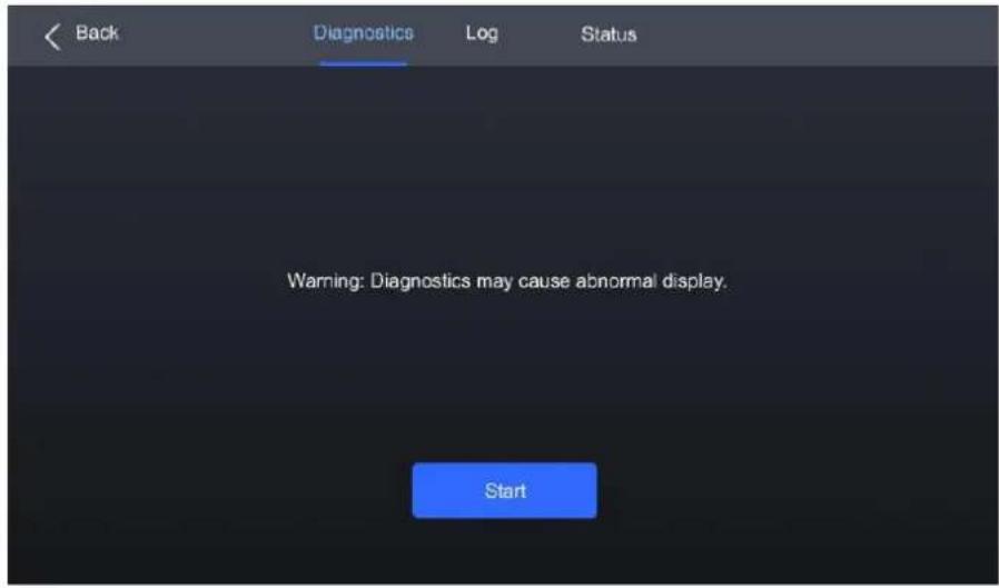
Step 2 Navigate to the Diagnostics tab and select Start.
Step 3 Once the diagnostic process is completed, select Details to check the diagnostic result. You can also select Export to export the result into a USB drive.
5.6.2 View and Export Logs
To export the logs, insert a USB drive to the USB port on the front panel of the device.
Step 1 Select Maintain from the main menu to access the settings interface.
Step 2 Navigate to the Log tab to check the device logs.
Figure 5-17 Device log
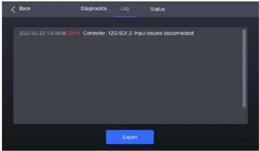
Step 3 Select Export to export the logs into a USB drive.
5.6.3 Check Device Status
Step 1 Select Maintain from the main menu to access the settings interface.
Step 2 Navigate to the Status tab to check the device status.
Figure 5-18 Check device status
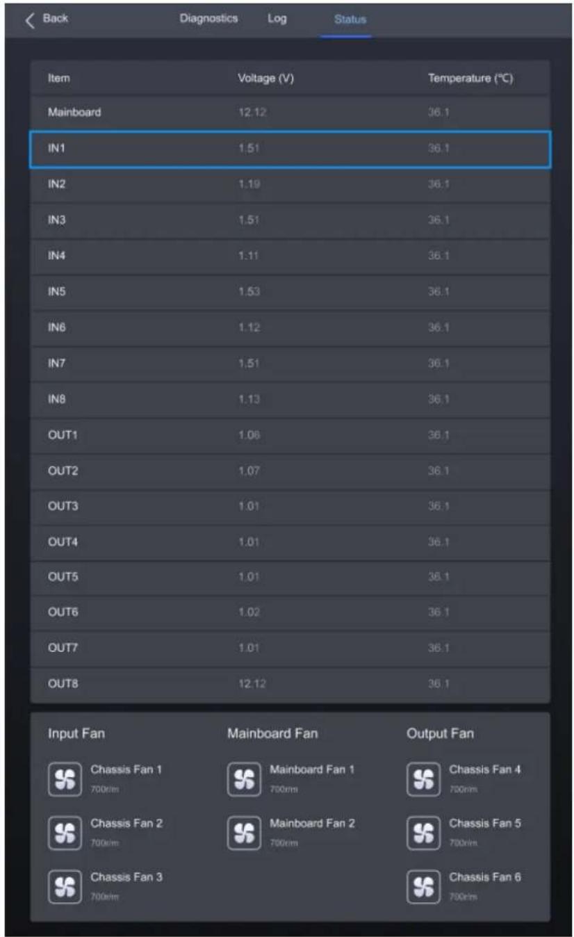
6 Specifications
| Electrical Specifications | Power supply | 100-127V~/200-240V~,15A/10A,50/60Hz |
| Power Consumption | 625 W | |
| Operating Environment | Temperature | -10°C to +60°C |
| Humidity | 0% RH to 80% RH, non-condensing | |
| Storage Environment | Temperature | -10°C to +60°C |
| Humidity | 0% RH to 90% RH, non-condensing | |
| Physical Specifications | Dimensions | 482.6 mm × 282.9 mm × 538.8 mm (foot pad included) |
| Net weight | 31 kg (without cards) | |
| Packing Information | Packing box | 725.0 mm × 635.0 mm × 410.0 mm, kraft paper box |
| Accessories | 1x Power cord, 1x Ethernet cable1x Quick Start Guide, 1x Customer Letter, 1x Safety Manual,1x Certificate of Approval | |
| IP Rating | IP20Please prevent the product from water intrusion and do not wet or wash the product. | |
| Noise Level (typical at 25°C/77°F) | 53 dB (A) | |
The amount of power consumption may vary depending on various factors such as product settings, usage, and environment.
7 Video Source Specifications
| Input | Bit Depth | Sampling Format | Max Input Resolution |
| HDMI 2.0 | 8bit | RGB 4:4:4 | 4096×2160@60Hz |
| YCbCr 4:4:4 | |||
| YCbCr 4:2:2 | |||
| 10bit | RGB 4:4:4 | 4096×2160@48Hz | |
| YCbCr 4:4:4 | |||
| YCbCr 4:2:2 | 4096×2160@60Hz | ||
| 12bit | RGB 4:4:4 | 4096×2160@30Hz | |
| YCbCr 4:4:4 | |||
| YCbCr 4:2:2 | 4096×2160@60Hz | ||
| HDMI 2.1 | 8bit/10bit/12bit | RGB 4:4:4 | 8192×4320@30Hz |
| YCbCr 4:4:4 | |||
| YCbCr 4:2:2 | |||
| DP 1.2 | 8bit | RGB 4:4:4 | 4096×2160@60Hz |
| YCbCr 4:4:4 | |||
| YCbCr 4:2:2 | |||
| 10bit | RGB 4:4:4 | 4096×2160@60Hz | |
| YCbCr 4:4:4 | |||
| YCbCr 4:2:2 | |||
| 12bit | RGB 4:4:4 | 4096×2160@50Hz | |
| YCbCr 4:4:4 | |||
| YCbCr 4:2:2 | 4096×2160@60Hz | ||
| DP 1.4 | 8bit | RGB 4:4:4 | 7680×4320@30Hz |
| YCbCr 4:4:4 | |||
| YCbCr 4:2:2 | |||
| 10bit | RGB 4:4:4 | 7680×4320@24Hz | |
| YCbCr 4:4:4 | |||
| YCbCr 4:2:2 | 7680×4320@30Hz | ||
| 12bit | RGB 4:4:4 | 5120×2160@60Hz | |
| YCbCr 4:4:4 | |||
| YCbCr 4:2:2 | 7680×4320@30Hz | ||
| 12G-SDI | 10bit | YCbCr 4:2:2 | 4096×2160@60Hz |
8 Ethernet Port Load Capacity
8.1 1G Solution (MX\_4x10G\_Fiber Output Card)
When Working with A10s Pro Receiving Card
When working with the A10s Pro receiving card, the formula of calculating the load capacity per Ethernet port and the detailed parameters are as follows:
- 8bit: Load capacity × 24 × Frame rate < 1000 × 1000 × 1000 × 0.95
- 10bit: Load capacity × 32 × Frame rate < 1000 × 1000 × 1000 × 0.95
- 12bit: Load capacity × 48 × Frame rate < 1000 × 1000 × 1000 × 0.95
| Max Load Capacity per Ethernet Port (Pixels) | |||
| Frame Rate / Bit Depth | 8bit | 10bit | 12bit |
| 24Hz | 1,649,306 | 1,236,979 | 824,653 |
| 25Hz | 1,583,333 | 1,187,500 | 791,667 |
| 30Hz | 1,319,444 | 989,583 | 659,722 |
| 50Hz | 791,667 | 593,750 | 395,833 |
| 60 Hz | 659,722 | 494,792 | 329,861 |
| 120Hz | 329,861 | 247,396 | 164,931 |
| 144Hz | 274,884 | 206,163 | 137,442 |
| 240Hz | 164,931 | 123,698 | 82,465 |
When Working with Other Armor Series Receiving Cards
When working with other Armor series receiving cards, the formula of calculating the load capacity per Ethernet port and the detailed parameters are as follows:
- 8bit: Load capacity × 24 × Frame rate < 1000 × 1000 × 1000 × 0.95
• 10bit: Load capacity × 48 × Frame rate < 1000 × 1000 × 1000 × 0.95
● 12bit: Load capacity × 48 × Frame rate < 1000 × 1000 × 1000 × 0.95
| Max Load Capacity per Ethernet Port (Pixels) | |||
| Frame Rate / Bit Depth | 8bit | 10bit | 12bit |
| 24Hz | 1,649,306 | 824,653 | 824,653 |
| 25Hz | 1,583,333 | 791,667 | 791,667 |
| 30Hz | 1,319,444 | 659,722 | 659,722 |
| 50Hz | 791,667 | 395,833 | 395,833 |
| 60 Hz | 659,722 | 329,861 | 329,861 |
| 120Hz | 329,861 | 164,931 | 164,931 |
| 144Hz | 274,884 | 137,442 | 137,442 |
| 240Hz | 164,931 | 82,465 | 82,465 |
8.2 5G Solution (CX\_1x40G\_Fiber Output Card)
When working with the CA50E, CA50C, or XA50 receiving cards, the formula of calculating the load capacity per Ethernet port and the detailed parameters are as follows:
- 8bit: Load capacity × 24 × Frame rate < 5G × 0.75
• 10bit: Load capacity × 30 × Frame rate < 5G × 0.75
● 12bit: Load capacity × 36 × Frame rate < 5G × 0.75
| Max Load Capacity per Ethernet Port (Pixels) | |||
| Frame Rate / Bit Depth | 8bit | 10bit | 12bit |
| 24Hz | 6,480,000 | 5,182,500 | 4,320,000 |
| 25Hz | 6,220,800 | 4,975,200 | 4,147,200 |
| 30Hz | 5,184,000 | 4,146,000 | 3,456,000 |
| 50Hz | 3,110,400 | 2,487,600 | 2,073,600 |
| 60 Hz | 2,592,000 | 2,073,000 | 1,728,000 |
| 120Hz | 1,296,000 | 1,036,500 | 864,000 |
| 144Hz | 1,080,864 | 864,441 | 720,576 |
| 240Hz | 648,000 | 518,250 | 432,000 |
Copyright © 2023 Xi'an NovaStar Tech Co., Ltd. All Rights Reserved.
No part of this document may be copied, reproduced, extracted or transmitted in any form or by any means without the prior written consent of Xi'an NovaStar Tech Co., Ltd.
Trademark
NOVA STAR is a trademark of Xi'an NovaStar Tech Co., Ltd.
Statement
Thank you for choosing NovaStar's product. This document is intended to help you understand and use the product. For accuracy and reliability, NovaStar may make improvements and/or changes to this document at any time and without notice. If you experience any problems in use or have any suggestions, please contact us via the contact information given in this document. We will do our best to solve any issues, as well as evaluate and implement any suggestions.



- Contents
- Introduction
- Appearance
- Front Panel
- Rear Panel
- Note
- Applications
- Solution Build
- 1G Solution (MX\_4x10G\_Fiber Output Card)
- 5G Solution (CX\_1x40G\_Fiber Output Card)
- VMP Operations
- Connect to VMP
- Via Ethernet Cable
- Via LAN
- UI Introduction
- Note:
- Device Management
- Export and Import Project Files
- Notice
- Export Project Files
- Import Project Files
- Manage Device Groups
- Operating Procedure
- Set Backup Device
- Screen Configuration
- New Screen
- Configure Screen Topology
- Use the function buttons
- Use the function menus on the menu bar
- Use the right-click function menus
- Set cabinet coordinates and rotation
- Set Card Backup
- Set the Cabinet
- Control Display Status
- Enable Indicator
- Enable the Light Up Slowly Function
- Set Test Pattern
- Set Image for Abnormal Situations
- Input Source Configuration
- Add Layers
- Lock layer
- Switch source
- Adjust layer size and position
- Set borders
- Crop the input source
- Set External Sources
- Set DP 1.4 Mode
- View Source Information
- Set EDID
- Adjust Color
- Set HDR Parameters
- Set Internal Sources
- Set the Image
- Set the Resolution, Refresh Rate, and Bit Depth
- Display Correction
- Correct Seams
- Correct Multi-Batch Cabinets/Modules
- Lock and Unlock Correction Page
- Color Processing
- Color Replacement
- 14Ch Color Correction
- Set Color Curves
- Enable 3D LUT
- Prerequisites
- Screen Settings
- Adjust Image Quality
- Adjust Brightness and Gamma
- Set LED Image Booster
- Apply Calibration Effect
- Related Information
- Set Thermal Compensation
- Adjust EOTF
- Set Output
- Set Output Bit Depth and Additional Frame Latency
- Set Sync Parameters
- Set Frame Multiplication
- Set Shutter Fit
- Enable 3D Function
- Check the Load
- Preset Management
- Save Presets
- Apply Presets
- Manage Presets
- Modify a Preset
- Delete a Preset
- Clear Presets
- Import and Export Presets
- Import Presets
- Export Presets
- Screen Monitoring
- Check Device Status
- Check Monitoring Records
- Search records
- Query records
- Set how the records are displayed
- Clear records
- Export records
- Calibration Coefficient Management
- Upload Calibration Coefficients
- Edit Calibration Coefficients
- 12.3 View Calibration Effect
- Set the Display Content
- Enable and Disable Calibration Effect
- Save Calibration Coefficients
- Read Back Calibration Coefficients
- Export Calibration Coefficients
- Screen Maintenance
- Maintain Controllers
- Operations in Device List
- Check the device Information
- + Change the time
- + Change the time zone
- Export Logs
- + Rename the controller
- Enabling Mapping
- Operations on Controller Maintenance Page
- Find the controller
- Upgrade the firmware program
- Maintain Cabinets
- Software Settings
- Offline Mode
- 14.1 Change Language and Temperature Scale
- Manage Cabinet Library
- Upload NCP File
- Export NCP File
- Sync NCP File
- Check NCP File Information
- 14.3 Check User Manual
- 14.4 Check Software Information
- Check Keyboard Shortcuts
- Front Screen Panel
- UI Introduction
- Home Screen
- Main menu
- Screen
- Set Brightness, Color Temperature and Gamma
- Set Screen Status
- Input
- Set Internal Source
- Check Input Source Information
- Set EDID
- Set HDR
- Communication
- Settings
- Configure LCD Screen
- Setting Language
- Set Temperature Scale
- Factory Reset
- Maintenance
- Diagnostics
- View and Export Logs
- Check Device Status
- Specifications
- Ethernet Port Load Capacity
- 1G Solution (MX\_4x10G\_Fiber Output Card)
- When Working with A10s Pro Receiving Card
- When Working with Other Armor Series Receiving Cards
- 5G Solution (CX\_1x40G\_Fiber Output Card)
- Trademark
- Statement
Brand : NovaStar
Model : MX6000 Pro
Category : Contrôleur d'affichage LED