WV-S8544 - Security Camera i-PRO - Free user manual and instructions
Find the device manual for free WV-S8544 i-PRO in PDF.


| Product Type | Security Camera (Network) |
| Model | WV-S8544 |
| Brand | i-PRO |
| Image Sensor | 1/1.8" Progressive CMOS |
| Effective Pixels | Approx. 8.29 Megapixels (4K) |
| Min. Illumination | Color: 0.03 Lux (F1.2), B/W: 0.003 Lux (F1.2) |
| Lens | 2.8-8.8 mm, F1.2 (motorized varifocal) |
| Angle of View | Horizontal: 36.8° (tele) - 97.6° (wide) |
| Day/Night | ICR (Auto / Off / On) |
| Maximum Resolution | 3840x2160 (4K) @ 30 fps |
| Compression | H.265 / H.264 / JPEG |
| Network Interface | 10/100/1000 Mbps Ethernet (RJ-45) |
| Audio Support | 2-way audio (mic in/line out) |
| Storage | MicroSD/SDHC/SDXC slot (max 512 GB) |
| Power Supply | PoE+ (IEEE 802.3at) or DC 12V 1.0A |
| Power Consumption | 12W (PoE+) or 9W (DC) |
| Dimensions (W x H x D) | Approx. 150 x 68 x 68 mm |
| Weight | Approx. 0.65 kg (1.43 lb) |
| Ingress Protection | IP66 (outdoor use) |
| Vandal Resistance | IK10 (metal casing) |
| Operating Temperature | -40°C to +55°C (-40°F to 131°F) |
| Operating Humidity | 5% to 95% (non-condensing) |
| Main Features | 4K, Smart Coding, Face Detection, Edge Recording, ONVIF G/T |
| Maintenance & Cleaning | Use soft cloth; avoid solvents. Clean lens with air blower. |
| Safety Certifications | CE, FCC, UL, CB, RoHS |
| Spare Parts & Repairability | Contact i-PRO support for replacement parts. Repairs by authorized centers. |
Frequently Asked Questions - WV-S8544 i-PRO
User questions about WV-S8544 i-PRO
0 question about this device. Answer the ones you know or ask your own.
Ask a new question about this device
Download the instructions for your Security Camera in PDF format for free! Find your manual WV-S8544 - i-PRO and take your electronic device back in hand. On this page are published all the documents necessary for the use of your device. WV-S8544 by i-PRO.
USER MANUAL WV-S8544 i-PRO
Network Camera For professional use only Outdoor use
Model No. WV-S8574L, WV-S8573L WV-S8564L, WV-S8563L WV-S8544L, WV-S8543L WV-S8544, WV-S8543
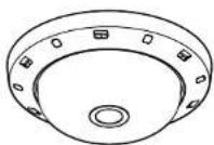
WV-S8574L
About the user manuals
Product documentation is composed of the following documents.
- Installation Guide (this document): Provides information about "Precautions", "Precautions for installation" and the installation method.
- Basic Information (Refer to the link on the following support website): Provides information about "Precautions for use" and "Detail specifications".
- Operating Instructions (Refer to the link on the following support website): Explains how to perform the settings and how to operate this camera. https://i-pro.com/global/en/surveillance/training-support/documentation-databas
"<Control No.: C"^* used in these documents should be used to search for information on our technical information website (https://i-pro.com/global/en/surveillance/training-support/support/technical-information) and will guide you to the right information."
- Before attempting to connect or operate this product, please read these instructions carefully and save this manual for future use.
- microSDXC/ microSDHC/ microSD memory card is described as microSD memory card.
- The external appearance and other parts shown in this manual may differ from the actual product within the scope that will not interfere with normal use due to improvement of the product.
For U.S. and Canada:
i-PRO Americas Inc.
https://www.i-pro.com/
For Europe and other countries:
i-PRO Co., Ltd. Fukuoka, Japan
https://www.i-pro.com/
i-PRO EMEA B.V. UK Branch 1010 Cambourne Business Park, Cambridgeshire CB23 6DP
Authorised Representative in EU: i-PRO EMEA B.V. Laarderhoogtweg 25, 1101 EB Amsterdam, Netherlands

av0322-2082 PGQP8398XA
Disposal of Old Equipment and Batteries
Only for European Union and countries with recycling systems

These symbols on the products, packaging, and/or accompanying documents mean that used electrical and electronic products and batteries must not be mixed with general household waste. For proper treatment, recovery and recycling of old products and used batteries, please take them to applicable collection points in accordance with your national legislation.
By disposing of them correctly, you will help to save valuable resources and prevent any potential negative effects on human health and the environment.
For more information about collection and recycling, please contact your local authority. Penalties may be applicable for incorrect disposal of this waste, in accordance with national legislation.

Note for the battery symbol (bottom symbol)
This symbol might be used in combination with a chemical symbol. In this case it complies with the requirement set by the Directive for the chemical involved.
For U.S.A.
NOTE: This equipment has been tested and found to comply with the limits for a Class A digital device, pursuant to Part 15 of the FCO Rules. These limits are designed to provide reasonable protection against harmful interference when the equipment is operated in a commercial environment. This equipment generates, uses, and can radiate radio frequency energy and, if not installed and used in accordance with the instruction manual, may cause harmful interference to radio communications.
Operation of this equipment in a residential area is likely to cause harmful interference in which case the user will be required to correct the interference at his own expense.
FCC CAUTION: Changes or modifications not expressly approved by the party responsible for compliance could void the user's authority to operate the equipment.
Supplier's Declaration of conformity Trade name : i-PRO
Model No.: WV-S8574L, WV-S8573L WV-S8564L, WV-S8563L WV-S8544L, WV-S8543L
Responsible Party : I-PRO Americas Inc. 8550 Fallbrook Drive, Suite 200 Houston, Texas 77064 Support Contact : 1-800-513-5417

For U.S.A.
The model number and serial number of this product may be found on the surface of the unit. You should note the model number and serial number of this unit in the space provided and retain this book as a permanent record of your purchase to aid identification in the event of theft.
Model No. Serial No.
For U.S.A.
This device complies with part 15 of the FCC Rules. Operation is subject to the following two conditions: (1) This device may not cause harmful interference, and (2) this device must accept any interference received, including interference that may cause undesired operation.
- For Canada____ CAN ICES-3(A)/NMB-3(A)
Precautions 2
About notations....3
Open Source Software 3
Copyright 3
Trademarks and registered trademarks....5
Precautions for installation....3
Troubleshooting....3
Specifications....4
Optional accessories 4
Standard accessories....4
Other items that are needed (not included) .....4
Installation Procedure 5
WARNING:
• Operation of this product in a residential environment could cause radio interference.
Caution:
- The network camera is only intended for a connection to an ethernet or PoE+ network without routing to the outside plant.
- This product has no power switch. Be sure to install disconnect devices such as a circuit breaker to shut down the main power of power supplying equipment to this product.
- Before attempting to connect or operate this product, please read these instructions carefully.
Notice:
- This product is not suitable for use in locations where children are likely to be present.
- Do not install this product in locations where ordinary persons can easily reach.
• This product is a professional equipment. - For information about screws and other parts required for installation, refer to the corresponding section of this document.

Direct current symbol
Precautions
■ Do not insert any foreign objects.
Fire or electrical shock may be caused if water or any foreign objects, such as metal objects, enter inside the unit. Turn the power off immediately and contact qualified service personnel for service.
■ Do not use this product in an inflammable atmosphere.
Failure to observe this may cause an explosion resulting in injury.
■ Avoid installing this product in the locations where salt damage occurs or corrosive gas is produced. Otherwise, the mounting portions will deteriorate and injury or accidents due to a fall of the product may occur.
■ Do not strike or give a strong shock to this product.
Failure to observe this may cause injury or fire.
- Keep microSD memory cards away from infants and children.
Otherwise, they may swallow the cards by mistake.
In this case, consult a doctor immediately.
■ Do not hang down from this product or use this product as a pedestal.
Failure to observe this may cause injury or accidents.
■ Do not install this product on a place that is greatly influenced by wind.
Installation on a place where the wind speed is 60 m/s (approx. 134 mph) or more may cause a fall of the product resulting in injury or accidents.
Do not sprinkle more water, exceeding the performance limit of waterproof with a high pressure cleaning machine, etc.
Fire or electrical shock may be caused by immersion.
■ Do not attempt to disassemble or modify this product.
Failure to observe this may cause fire or electric shock. Consult the dealer for the repair or inspections.
■ Do not install or clean the camera, or touch this product, the power cable or the connected cables during thunder storms.
Failure to observe this may cause electric shock.
■ Refer installation work to the dealer.
Installation work requires technique and experience. Failure to observe this may cause fire, electric shock, injury, or damage to the product. Be sure to consult the dealer.
■ Stop the operation immediately when something is wrong with this product.
When smoke goes up from the product, the smell of smoke comes from the product, or the exterior of the product has deteriorated, continued use will cause a fire or fall of the product resulting in injury, or damage to the product. In this case, turn the power off immediately and contact qualified service personnel for service.
■ Select an installation area that can support the total weight.
Selecting an inappropriate installation surface may cause this product to fall down or topple over, resulting in injury or accidents. Installation work shall be started after sufficient reinforcement.
Periodic inspections shall be conducted.
Rust on the metal parts or screws may cause a fall of the product resulting in injury or accidents. Consult the dealer for the inspections.
■ The exclusively designed mount bracket shall be used.
Failure to observe this may cause a drop resulting in injury or accidents.
Use the exclusively designed mount bracket for installation.
■ The screws and bolts must be tightened to the specified torque.
Failure to observe this may cause a drop resulting in injury or accidents.
■ Turn the power off when do wiring of this product.
Failure to observe this may cause electric shock. In addition, short circuit or wrong wiring may cause fire.
■ Install this product in a location high enough to avoid people and objects from bumping the product.
Failure to observe this may cause injury
■ Do not install this product in locations subject to vibration.
Loosening of mounting screws or bolts may cause a fall of the product resulting in injury or accidents.
■ Correctly perform all wiring.
Short circuits in the wiring or incorrect wiring may cause fire or electrical shock.
The measures of protection against snowfall shall be taken.
Weight of snow may cause a fall of the product resulting in injury or accidents. Protect the product against snowfall by installing it under eaves.
■ Install the product securely on an installation surface in accordance with the installation instructions.
Failure to observe this may cause injury or accidents.
■ Turn the power off when cleaning this product.
Failure to observe this may cause injury
■ Do not rub the edges of metal parts with your hand.
Failure to observe this may cause injury.
About notations
The following notations are used when describing the functions limited for specified models. The functions without the notations are supported by all models.
| S857xL | WV-S8571L, WV-S8573L | S856xL | WV-S8561L, WV-S8563L |
| S854xL | WV-S8541L, WV-S8543L | S854x | WV-S8544, WV-S8543 |
| S85x4x | WV-S8574L, WV-S8564L, WV-S8514L, WV-S8514 | S85x3x | WV-S8573L, WV-S8563L, WV-S8513L, WV-S8513 |


The functions with this notation are available when using the model with the clear dome cover.
The functions with this notation are available when using the model with the smoke dome cover.
Open Source Software
- This product contains open source software licensed under GPL (GNU General Public License), LGPL (GNU Lesser General Public License), etc.
- Customers can duplicate, distribute and modify the source code of the software under license of GPL and/or LGPL.
- For details concerning licensing and source code of open source software, click "Click here for OSS information"
on "Support" page of the setup menu of this product and read the displayed content. - Please note that we shall not respond to any inquiries regarding the contents of the source code.
Copyright
Except for open source software licensed under GPL/LGPL and so on, distributing, copying, disassembling, reverse compiling and reverse engineering of the software provided with this product are all expressly prohibited. In addition, exporting any software provided with this product violating export laws is prohibited.
Trademarks and registered trademarks
- Microsoft, Windows, Windows Media, Internet Explorer, Microsoft Edge, and ActiveX are either registered trademarks or trademarks of Microsoft Corporation in the United States and/or other countries.
- Intel and Intel Core are trademarks of Intel Corporation or its subsidiaries in the U.S. and/or other countries.
- Adobe, Acrobat, and Reader are either registered trademarks or trademarks of Adobe in the United States and/or other countries.
- microSDXC Logo is a trademark of SD-3C, LLC.
- iPad and iPhone are trademarks of Apple Inc., registered in the U.S. and other countries.
• Android and Google Chrome are trademark of Google LLC. - Firefox is a trademark of the Mozilla Foundation in the US and other countries.
- The word "QR Code" is a registered trademark of DENSO WAVE INCORPORATED in Japan and other countries.
- All other trademarks identified herein are the property of their respective owners.
Precautions for installation
i-PRO Co., Ltd. assumes no responsibility for injuries or property damage resulting from failures arising out of improper installation or operation inconsistent with this documentation.
In order to prevent injury, the product must be securely mounted to an installation surface according to Installation Guide.
■ Installation area for this product
Select an appropriate place for the installation area (such as a strong installation surface) in your particular environment.
- Make sure that the installation area is strong enough to hold this product, such as a concrete ceiling.
• Install the camera in the foundation area of the architecture or where sufficient strength is assured.
- Do not mount the product on a plaster board or a wooden section because they are too weak. If the product is unavoidably mounted on such a section, the section shall be sufficiently reinforced.
■ Mounting method for this product.
This product is designed to be used as a pendant mount carmer. If the product is mounted on a desktop or at a slant, it may not work correctly and its lifetime may be shortened.
■ Do not place this product in the following places
- Locations where a chemical agent is used such as a swimming pool
- Locations subject to moisture or oil smoke such as a kitchen
- Locations that have a specific environment that is subject to an inflammable atmosphere or solvents
- Locations where a radiation, an X-ray, a strong radio wave or a strong magnetic field is generated
- Locations near coasts directly subjected to sea breezes, or locations subject to corrosive gases such as from hot springs, volcanic regions, etc.
- Locations where the temperature is not within the specified range
- Locations subject to vibrations, such as on vehicles, marine vessels, or above product lines (This product is not designed for on-vehicle use.)
• Locations subject to condensation as the result of severe changes in temperature - Locations near rubber products (packing, rubber feet, etc.)
■ Screw tightening
Do not use an impact driver. Use of an impact driver may damage the screws or cause tightening excessively.
■ Installing in low temperature environments
This product is equipped with an internal heater unit for use in cold climates. The heater unit tums on automatically when the temperature inside the product drops below around 0°C [32°F]. S854xL S854x
When this product is installed and operated in low temperatures below -10 °C (14 °F) S854xL S854x
-20 °C [-4 °F] S857xL 3656xL , it may require time to start up since the camera will wait to be warmed up internally by the internal heater right after the power is turned on. Also, the camera may not function properly, if it is installed and operated in an environment where the temperature is below -25 °C [-13 °F]. In such a case, wait approximately 2 hours or more until the camera is warmed up. Then, turn on the power again.
As the camera warms up, snow or frost accumulated on the front panel will melt. However, it may not be defrosted from the cover depending on the ambient temperature or weather condition.
■ About reflection of light from outside or IR light
A ghost may appear on the screen depending on the incident angle of external light.
In the case of using the IR light, installation of a camera near a wall may cause reflection of infrared rays resulting in a part of the screen or the entire screen turning whitish.
- Refer to our technical information website
■ Take notice of humidity
Install this product when the humidity is low. If installation is performed when it is raining or in very humid conditions, the inside may be affected by humidity, causing mist-over inside the dome cover.
■ Protection from lightning
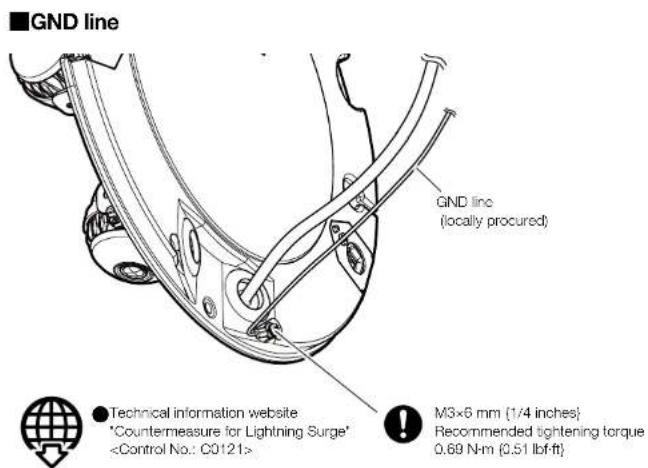
When cables are used outdoors, there is a chance that they may be affected by lightning. In such a case, install a lightning arrestor close to the camera, and make the length of the network cable between the camera and lightning arrestor as short as possible to prevent the camera from being affected by lightning.
■ When noise disturbance may happen
Noise may appear in video or audio near a strong electric field from a TV or radio antenna, motors and transformers, or a strong electric field/magnetic field from a power line (lamp line) of AC100 V or more. Conduct the power distribution work to keep 1 m [3.28 foot] away from them or conduct the electric conduit work using metal pipes. (Be sure to make ground connection of the metal pipes.)
■ Make sure to remove this product if it will no longer be used.
This product has no power switch.
When turning off the power, disconnect the power supply from the PoE+ device.
■ About the battery
A battery is installed inside the camera. Do not leave the battery exposed in environments of excessive heat as a result of sunlight or fire.
■ Equipment classification and power source indication label
Refer to the indication label on the bottom side of this unit for the equipment classification, power source, and other information.
■ About static electricity
Before installing or removing this product, be sure to touch metal objects to discharge static electricity from your body.
Troubleshooting
Before requesting service, refer to "Troubleshooting" of Basic Information and Operating Instructions. Then, confirm the trouble.
Specifications*
*For further information, refer to the Basic Information.
| Power source *: | PoE+ (IEEE802.3at compliant) |
| Power consumption *: | S857xLS856xLS854xLPoE+ DC 54 V: 470 mA/ Approx. 25.4 W (Class 4 device)S854xPoE+ DC 54 V: 320 mA/ Approx. 17.3 W (Class 4 device) |
| Operating environment | |
| Ambient operating temperature: | -40 °C to +60 °C -(-40 °F to +140 °F){Power On range: -20 °C to +60 °C (-1 °F to +140 °F)}Maximum temperature according to NEMA TS 2 (2.2.7): 74 °C (165 °F) |
| Ambient operating humidity: | 10 % to 100 % (no condensation) |
| Storage environment | |
| Storage temperature: | -30 °C to +60 °C (-22 °F to +140 °F) |
| Storage humidity: | 10 % to 95 % (no condensation) |
| EXT I/O terminals *: | ALARM IN1(Alarm input 1/ Black & white input/ Auto time adjustment input) (x1)ALARM IN2 (Alarm input 2/ ALARM OUT) (x1)ALARM IN3 (Alarm input 3/ ALARM OUT/ AUX OUT) (x1) |
| Audio input: | ø3.5 mm stereo mini jack |
| For microphone input: | Recommended applicable microphone: Plug-in power type(Sensitivity of microphone: -48 dBu3 dB (0 dB= 1 V/Pa, 1 kHz))Input impedance: Approx. 2 kΩ (unbalanced)Supply voltage: 2.4 V ±0.5 V |
| For line input: | Input level: Approx. -10 dBV |
| Audio output: | ø3.5 mm stereo mini jack (Audio output is monaural.)Output impedance: Approx. 600 Ω (unbalanced)Output level: -20 dBV |
| Waterproof *: | IP66/ IP67 (IEC 60529), Type 4X (UL50C)NEMA 4X compliant |
| Shock resistance: | IK10 (IEC 62262) |
| Other standard support: NEMA | TS 2 (2.2.7-2.2.9) |
| Wind resistance: | Up to 40 m/s {approx. 89 mph} |
| Dimensions: | ø300 mm × 90 mm (H) {ø11-13/16 inches × 3-17/32 inches (H)} |
| Mass: | Approx. 3.3 kg {7.28 lbs} S85x4x Approx. 3.1 kg {6.83 lbs} S85x3x |
| Finish: | Main body: Aluminum die cast, i-PRO whiteOuter fixing screws: Stainless steel (Corrosion-resistant treatment)Domc cover: PC resin, © |
| Others: | Tamper-resistant enclosure* |
*1 Refer to our technical information website
*2 When using with the IR LED light constantly lit, the upper limit of the operating temperature range is 50 °C (122 °F).
*3 Refer to the Operating Instructions for further information about the EXT I/O terminal settings.
Input specification : No-voltage make contact input (4 V - 5 V DC, internally pulled up)
OFF: Open or 4 V - 5 V DC
ON: Make contact with GND (required drive current: 1 mA or more)
Output specification : Open collector output (maximum applied voltage: 20 V DC)
OPEN: 4 V - 5 V DC by internal pull-up
*4 Only when installation work is properly performed according to the Installation Guide and appropriate waterproof treatment is performed.
*5 Component that has a structure on which the screws that are accessible after installation cannot be screwed or unscrewed using an ordinary screwdriver.
Optional accessories
Ceiling mount bracket: WV-OCL501-W Mount bracket: WV-QSR503-W
Wall mount bracket; WV-QWL501-W Mount bracket; WV-QSR503F-W
Attachment pipe bracket: WV-QAT500-W Mount bracket: WV-QSR503F1-W
Base bracket: WV QJB503 W Mount bracket: WV QSR503M W
Dome cover (Smoke type): WV-QDC501G Mount bracket: WV-QSR503M1-W
I/O cable: WV-QCA501A

The latest information → Technical information website "Accessory Selector"
Standard accessories
| Installation Guide (this document)....1 pc. | IMPORTANT SAFETY INSTRUCTIONS....1 pc. |
| Installation procedure leaflet....1 pc. | Code label*....1 pc. |
*1 This label may be required for network management. Use caution not to lose this label.
The following parts are used during installation procedures.
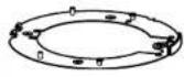 Attachment plate 1x Template A 1x Attachment plate 1x Template A 1x | 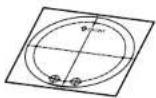 | 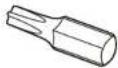 Bit 1x (Hex wrench, screw size 6.35 mm {1/4 inches} T20) Bit 1x (Hex wrench, screw size 6.35 mm {1/4 inches} T20) |  Grommet 2x(of them, 1 for spare) Grommet 2x(of them, 1 for spare) |
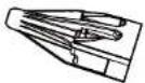 Attachment for the conduit 1x Attachment for the conduit 1x | 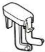 Scrow cover 1x (spare) Scrow cover 1x (spare) | ||
Other items that are needed (not included)
- Fixing screw
| Installation method | Recommended screw ^1 | Minimum pull-out strength ^2 | |
| Gangbox/Junction box | : Mount the camera on a gangbox/junction box using the attachment plate | M4 × 16 mm(5/8 inches) × 4 pcs. ^3 | 539 N (121 lbf) |
| Directly mount | : Directly mount the camera onto the installation surface using the attachment plate | ||
| Mount the camera using the exclusively designed mount bracket. | Refer to the operating instructions of each bracket. | ||
*1 Select screws according to the material of the location that the camera will be mounted to. In this case, wood screws and nails should not be used.
*2 This value indicates the minimum pull-out strength required value per screw. For information about the minimum pull-out strength, refer to our technical information website
^3 The screw length is an example when installing the camera on a robust installation surface with a thickness of 20 mm {25/32 inches} or more.
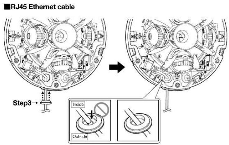
- Ethernet cable with RJ45 plug (category 5e or better, straight, all 4 pairs (8 pins))
- As necessary, audio input cable, audio output cable, alarm I/O cables
- Tools
Installation Procedure
Parts and functions

Lights

Lights off

Blinks

● Operating Instructions "Indicators"


All off
● Operating Instructions "SD memory card format"
● Basic Information
"Insert / remove a microSD memory card"
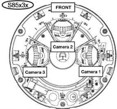
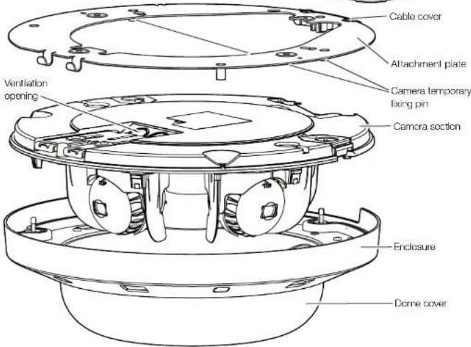
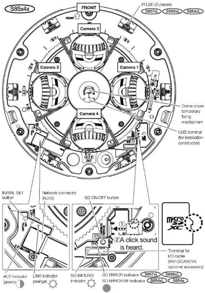
Step1
Common
Preparations
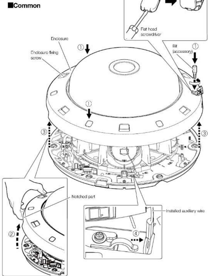
Step1
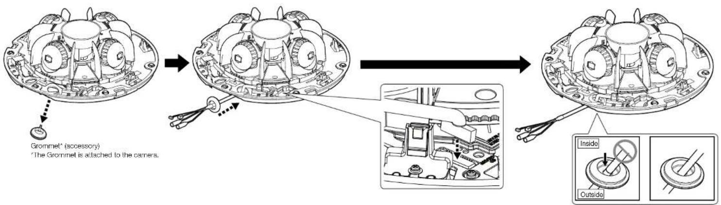
Preparations (Continued)
■When wiring on the side or using the conduit
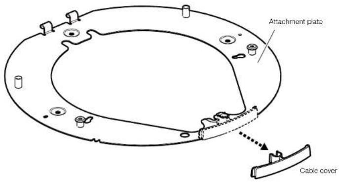
■When using an I/O cable (WV-QCA501A: optional accessory)
Step2

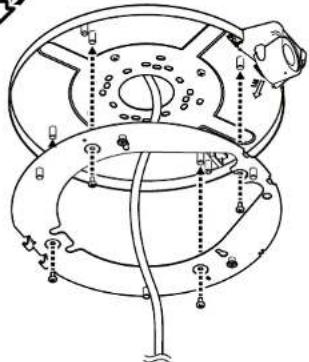
Minimum pull-out strength: 196 N {44 lbf} (per 1 pc.) M4 (4 pcs.) (locally procured)
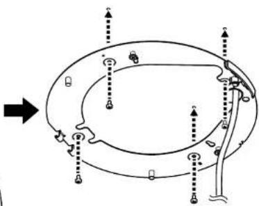
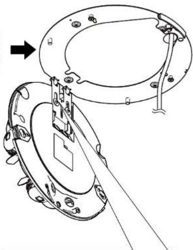
■Directly mount the camera
When using a multi-cable When using only an Ethernet cable
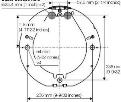
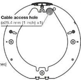
Cable access hole
flowchart
graph TD
    A["Top Left"] --> B["Top Right"]
    B --> C["Bottom Left"]
    C --> D["Bottom Right"]
    D --> E["Bottom Left"]
    E --> F["Bottom Right"]
    F --> G["Bottom Left"]
    G --> H["Bottom Right"]
    H --> I["Bottom Left"]
    I --> J["Bottom Right"]
    J --> K["Bottom Left"]
    K --> L["Bottom Right"]
    L --> M["Bottom Left"]
    M --> N["Bottom Right"]
    N --> O["Bottom Left"]
    O --> P["Bottom Right"]
    P --> Q["Bottom Left"]
    Q --> R["Bottom Right"]
    R --> S["Bottom Left"]
    S --> T["Bottom Right"]
    T --> U["Bottom Left"]
    U --> V["Bottom Right"]
    V --> W["Bottom Left"]
    W --> X["Bottom Right"]
    X --> Y["Bottom Left"]
    Y --> Z["Bottom Right"]
natural_image
Technical line drawing of a mechanical assembly with no visible text or symbolsConduit
Gangbox/ junction box

●Operating Instructions
WV-QJB503-W (Base bracket)
flowchart
graph TD
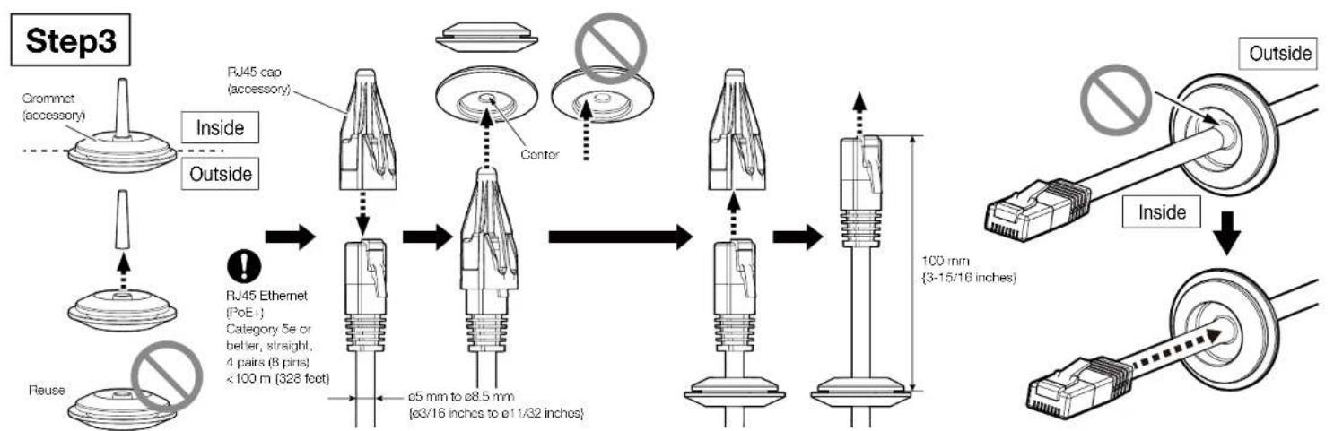
    A["Step3"] --> B["Grommet (accessory)"]
    B --> C["Inside"]
    C --> D["Outside"]
    D --> E["Reuse"]
    E --> F["RJ45 Ethernet (PoE)"]
    F --> G["Center"]
    G --> H["Outer Pin 1"]
    H --> I["Inner Pin 2"]
    I --> J["Outer Pin 3"]
    J --> K["Inner Pin 4"]
    K --> L["Outer Pin 5"]
    L --> M["Inner Pin 6"]
    M --> N["Outer Pin 7"]
    N --> O["Inner Pin 8"]
    O --> P["Outer Pin 9"]
    P --> Q["Inner Pin 10"]
    Q --> R["Outer Pin 11"]
    R --> S["Inner Pin 12"]
    S --> T["Outer Pin 13"]
    T --> U["Inner Pin 14"]
    U --> V["Outer Pin 15"]
    V --> W["Inner Pin 16"]
    W --> X["Outer Pin 17"]
    X --> Y["Inner Pin 18"]
    Y --> Z["Outer Pin 19"]
    Z --> AA["Inner Pin 20"]
    AA --> AB["Outer Pin 21"]
    AB --> AC["Inner Pin 22"]
    AC --> AD["Outer Pin 23"]
    AD --> AE["Inner Pin 24"]
    AE --> AF["Outer Pin 25"]
flowchart
graph LR
    A["Step5"] --> B["Camera temporary fixing mechanism"]
    B --> C["Locking Pin"]
    C --> D["Switch to Camera Section Securely"]
    D --> E["Final Assembly"]
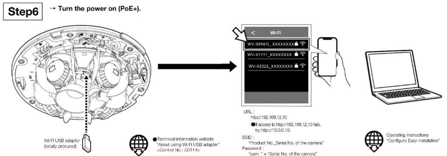
●Technical information website "About using Wi-Fi USB adapter"
URL:
http://192.168.12.10
●If access to http://192.168.12.10 fails, try http://10.0.0.10.
SSID
"Product No._Serial No. of the camera"
Password :
"cam_" + "Serial No. of the camera"
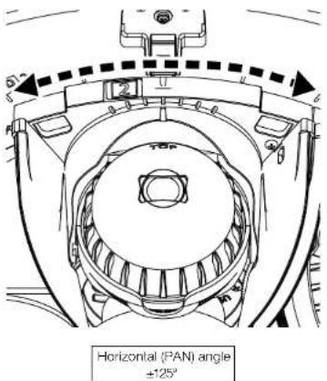
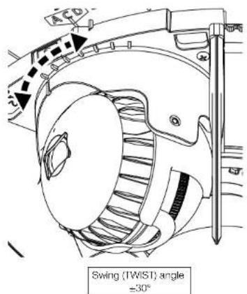
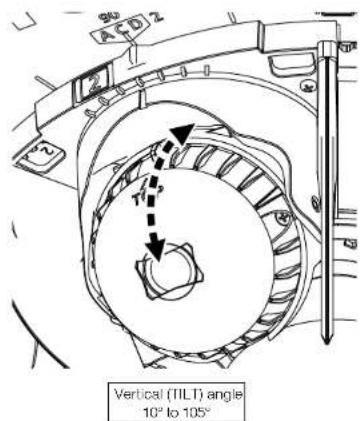
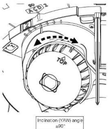
■How to adjust the camera (Each camera works in the same way.)
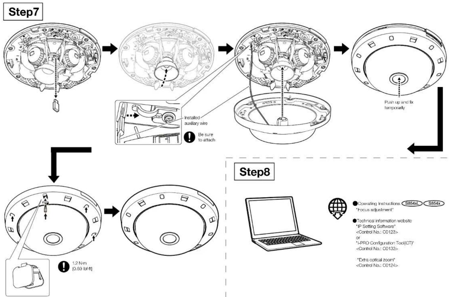
flowchart
graph TD
A["Step7"] --> B["Engine 1"]
B --> C["Engine 2"]
C --> D["Engine 3"]
D --> E["Engine 4"]
E --> F["Engine 5"]
F --> G["Engine 6"]
G --> H["Engine 7"]
subgraph Step8
I["1.2 N·m [0.89 lbf·ft"]]
J["Be sure to attach"]
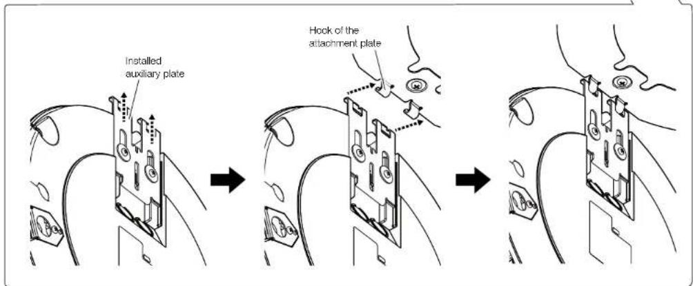
K["Installed auxiliary wire"]
L["Push up and fix temporarily"]
end
style A fill:#f9f,stroke:#333
style B fill:#f9f,stroke:#333
style C fill:#f9f,stroke:#333
style D fill:#f9f,stroke:#333
style E fill:#f9f,stroke:#333
style F fill:#f9f,stroke:#333
style G fill:#f9f,stroke:#333
style H fill:#f9f,stroke:#333
style I fill:#ccf,stroke:#333
style J fill:#ccf,stroke:#333
style K fill:#ccf,stroke:#333
style L fill:#ccf,stroke:#333
style_M["Operating Instructions S854xL S854x"] --> N["Focus adjustment"]
O["Technical information website "IP Setting Software" <Control No.: C0123> or "I-PRO Configuration Tool(ICT)" <Control No.: C0124>"] --> P[""Extra optical zoom" <Control No.: C0124"]
- About the user manuals
- For U.S. and Canada:
- For Europe and other countries:
- Disposal of Old Equipment and Batteries
- Note for the battery symbol (bottom symbol)
- WARNING:
- Caution:
- Notice:
- Precautions
- About notations
- Open Source Software
- Copyright
- Trademarks and registered trademarks
- Precautions for installation
- ■ Do not place this product in the following places
- Troubleshooting
- Optional accessories
- Installation Procedure
- Parts and functions
- Step1
- Preparations (Continued)
- Step2
- ■Directly mount the camera
- Conduit
- Gangbox/ junction box
Brand : i-PRO
Model : WV-S8544
Category : Security Camera