
MV-5 - Multiviseur vidéo Kramer - Free user manual and instructions
Find the device manual for free MV-5 Kramer in PDF.


| Product Type | 5-Channel Multiviewer with 16 inputs, multi-format support |
| Dimensions (W x D x H) | 19" x 9.45" x 2U (rack mountable) |
| Weight | 2.8 kg (6.17 lbs) approx. |
| Power Supply | 100-240V AC, 50/60Hz, 57VA |
| Inputs | 4 RGB/Component HD (BNC), 12 Analog SD (BNC), 5 DVI-D (1 background), 4 SDI (BNC) |
| Outputs | 1 RGB/Component HD (BNC), 1 DVI-D, 2 SDI (BNC) |
| Supported Resolutions (Output) | 480i to 1920x1200, including 1080p/60, 720p, and many PC formats |
| Maximum Data Rate | Up to 2.97 Gbps (3G HD-SDI compliant) |
| HDCP Support | On DVI inputs and outputs (configurable modes) |
| Control Interfaces | Front panel buttons, RS-232, RS-485, Ethernet (TCP/UDP) |
| Operating Temperature | 0° to +40°C (32° to 104°F) |
| Storage Temperature | -40° to +70°C (-40° to 158°F) |
| Humidity | 10% to 90%, RHL non-condensing |
| Key Features | Up to 4 windows + background, chroma key, image freeze/save, zoom up to 1000%, 16 user layouts, label insertion |
| Included Accessories | Power cord, rack ears, rubber feet, quick start guide |
| Cleaning | Wipe with a dry, soft cloth. Do not use liquids or solvents. |
| Safety | Use only supplied power cord. No user-serviceable parts inside. Disconnect power before cleaning or servicing. |
| Spare Parts & Repairability | Contact Kramer authorized service centers. Rack ears and power cord are replaceable. |
Frequently Asked Questions - MV-5 Kramer
User questions about MV-5 Kramer
0 question about this device. Answer the ones you know or ask your own.
Ask a new question about this device
Download the instructions for your Multiviseur vidéo in PDF format for free! Find your manual MV-5 - Kramer and take your electronic device back in hand. On this page are published all the documents necessary for the use of your device. MV-5 by Kramer.
USER MANUAL MV-5 Kramer
5 Channel Multiviewer
MV-5 5 Channel Multiviewer Quick Start Guide
This guide helps you install and use your product for the first time. For more detailed information, go to http://www.kramerelectronics.com/support/product_downloads.asp to download the latest manual or scan the QR code on the left.
Step 1: Check what's in the box

MV-5 5 Channel Multiviewer
Power cord
4 Rubber feet

1 Quick Start Guide
2 Rack "ears"

Save the original box and packaging materials in case your Kramer product needs to be returned to the factory for service.
Step 2: Install the MV-5
Mount the device in a rack (using the supplied rack "ears") or attach the rubber feet and place it on a shelf.
Step 3: Connect the inputs and outputs
Switch off the power to all devices before connecting them to your MV-5.

flowchart
graph TD
    A["HD-YUV Video Player"] --> B["Computer Graphics Source"]
    C["HD-YUV Video Player"] --> D["Computer Graphics Source"]
    E["Component Video Player"] --> F["3G HD-SDI Camera"]
    G["Composite Video Player"] --> H["SDI Player"]
    I["RGB/YUV Video Recorder"] --> J["Non-linear Editor"]
    K["Computer"] --> L["Computer Graphics Source"]
    M["Video Monitor"] --> N["Computer Graphics Source"]
    B --> O["Computer Graphics Source"]
    D --> P["Computer Graphics Source"]
    F --> Q["3G HD-SDI Camera"]
    H --> R["SDI Player"]
    J --> S["Non-linear Editor"]
    L --> T["Computer Graphics Source"]
    N --> U["Video Monitor"]
When connecting AV equipment to the MV-5 we recommend that you use Kramer high-performance cable for best results.
Step 4: Connect the power
Connect the MV-5 to the mains supply using the supplied power cord.
Step 5: Configure the MV-5
Configure the device either locally using the front panel buttons, or remotely using RS-232, RS-485 and Ethernet.

RS-232/Ethernet

Step 6: Operate the MV-5
Operate the device using the front panel controls, RS-232, RS-485 and Ethernet.
Contents
1 Introduction 1
2 Getting Started 2
2.1 Achieving the Best Performance 2
2.2 Safety Instructions 2
2.3 Recycling Kramer Products 3
2.4 Accessory to Medical Equipment (IEC 60601-1) 3
3 Overview 4
4 Defining the MV-5 5 Channel Multiviewer 6
5 Installing in a Rack 10
6 Connecting the MV-5 5 Channel Multiviewer 11
6.1 Connecting to the MV-5 Using the RS-232 Connection 14
6.2 Connecting to the MV-5 Using the RS-485 Connection 14
6.3 Connecting to the MV-5 Using Ethernet 14
7 Configuring and Operating the MV-5 Locally 18
7.1 Configuring the MV-5 Using the Menu 20
7.2 Operating the MV-5 Using the Front Panel Buttons 33
8 Configuring and Operating the MV-5 Remotely 43
8.1 The Multiviewer Main Window 44
8.2 The Menu Bar 45
8.3 The Quick Access Toolbar 51
8.4 Using the MV-5 Multiviewer Software 53
9 Upgrading the Firmware 60
10 Technical Specifications 61
11 Default Communication Parameters 62
12 Default EDID 63
13 Kramer Protocol 3000 64
13.1 Kramer Protocol 3000 Syntax 64
13.2 Kramer Protocol 3000 Commands 67
Figures
Figure 1: MV-5 5 Channel Multiviewer Front Panel 6
Figure 2: MV-5 5 Channel Multiviewer Rear Panel 8
Figure 3: Connecting the MV-5 5 Channel Multiviewer 12
Figure 4: Local Area Connection Properties Window 15
Figure 5: Internet Protocol Version 4 Properties Window 16
Figure 6: Internet Protocol Properties Window 17
Figure 7: Image Position and Scaling Example 35
Figure 8: MV-5 Controller Software Main Window 44
Figure 9: Background Color Window 46
Figure 10: Image Properties Window 47
Figure 11: Advanced Properties Window 48
Figure 12: Device Details Window 50
Figure 13: About MV-5 Window 51
Figure 14: Quick Access Toolbar 51
Figure 15: Quick Access Toolbar Icons 51
Figure 16: Connection Method Window 52
Figure 17: Windows Position 53
Figure 18: Switch Buttons 54
Figure 19: Layer Order 55
Figure 20: Switching an Input to a Window 56
Figure 21: Windows Setup Window 57
Figure 22: Input Button Properties Window 59
1 Introduction
Welcome to Kramer Electronics! Since 1981, Kramer Electronics has been providing a world of unique, creative, and affordable solutions to the vast range of problems that confront video, audio, presentation, and broadcasting professionals on a daily basis. In recent years, we have redesigned and upgraded most of our line, making the best even better!
Our 1,000-plus different models now appear in 11 groups that are clearly defined by function: GROUP 1: Distribution Amplifiers; GROUP 2: Switchers and Routers; GROUP 3: Control Systems; GROUP 4: Format/Standards Converters; GROUP 5: Range Extenders and Repeaters; GROUP 6: Specialty AV Products; GROUP 7: Scan Converters and Scalers; GROUP 8: Cables and Connectors; GROUP 9: Room Connectivity; GROUP 10: Accessories and Rack Adapters and GROUP 11: Sierra Video Products.
Congratulations on purchasing your Kramer MV-5 5 Channel Multiviewer which is ideal for:
• Professional broadcasting and production studios
• Presentation applications
- Post production
2 Getting Started
We recommend that you:
- Unpack the equipment carefully and save the original box and packaging materials for possible future shipment
- Review the contents of this user manual

Go to http://www.kramerav.com/manual/MV-5 to check for up-to-date user manuals, application programs, and to check if firmware upgrades are available (where appropriate).
2.1 Achieving the Best Performance
To achieve the best performance:
- Use only good quality connection cables (we recommend Kramer high-performance, high-resolution cables) to avoid interference, deterioration in signal quality due to poor matching, and elevated noise levels (often associated with low quality cables)
- Do not secure the cables in tight bundles or roll the slack into tight coils
- Avoid interference from neighboring electrical appliances that may adversely influence signal quality
• Position your MV-5 away from moisture, excessive sunlight and dust

This equipment is to be used only inside a building. It may only be connected to other equipment that is installed inside a building.
2.2 Safety Instructions

Caution: There are no operator serviceable parts inside the unit
Warning: Use only the power cord that is supplied with the unit
Warning: Do not open the unit. High voltages can cause electrical shock! Servicing by qualified personnel only
Warning: Disconnect the power and unplug the unit from the wall before installing
2.3 Recycling Kramer Products
The Waste Electrical and Electronic Equipment (WEEE) Directive 2002/96/EC aims to reduce the amount of WEEE sent for disposal to landfill or incineration by requiring it to be collected and recycled. To comply with the WEEE Directive, Kramer Electronics has made arrangements with the European Advanced Recycling Network (EARN) and will cover any costs of treatment, recycling and recovery of waste Kramer Electronics branded equipment on arrival at the EARN facility. For details of Kramer's recycling arrangements in your particular country go to our recycling pages at http://www.kramerav.com/support/recycling/.
2.4 Accessory to Medical Equipment (IEC 60601-1)
In the modern medical environment remote access is essential, for example, to transfer clinical data between doctors and to train to medical students. The MV-5 is certified according to the IEC 60601-1-2, Clause 2.1.3, Medical Electrical Equipment, Part 1: General Requirements for EMC standard which is required when accessory devices are used at locations where medical personnel and patients are present.
The MV-5 constitutes an optional component that can be considered necessary and suitable as part of medical equipment or for use as part of a medical system to provide real time simultaneous video feeds to those present at the local medical environment and at remote locations. In this environment, the MV-5 can be added to the system ONLY if the connecting equipment has been evaluated and meets the IEC 60601-1-2 EMC standards. Note, that when attaching accessory devices to a digital or analog interface, they must comply with the IEC standard for which they are used: EMC Standard (IEC 60601-1-2), Information Technology equipment (IEC 60950-1 (2ed)).
3 Overview
The MV-5 is a versatile, high-performance video and graphic multi-viewer for DVI signals, SD and HD analog signals up to 1920x1200@60Hz, and SDI signals up to 3G HD-SDI. The device can window up to four sources (plus a background) in any layout and output the image as SDI, DVI, component and composite video signals. Both preprogrammed and customizable screen division is supported.
In particular, the MV-5 features:
• 16 inputs with rapid selection and switching
- An input bandwidth of up to 3Gbps which supports standard definition, high definition and 3G high definition serial digital video signals
- SMPTE 259M, 292M and 424M input compliance and support for data rates of 270Mbps, 1.4835Gbps, 1.485Gbps, 2.967Gbps and 2.97Gbps
- Input-cable equalization up to 350m (1150ft) for SD signals, 140m (459ft) for 1.5GHz HD signals, and 120m (394ft) for 3GHz HD signals
SD means an NTSC or PAL compatible video format, consisting of 480 (for NTSC) or 576 (for PAL) lines of interlaced video. HD means a video format consisting of 720 active lines of progressive video or 1080 lines of progressive or interlaced video
- Any format to any format cross-conversion
- Any Standard to any standard cross-conversion
• HDCP support on DVI inputs/outputs
- Four independent chroma-key engines for each image layer
• Window and image scaling, zooming (up to 1000%), and aspect ratio control
• Independent layer transparency control
- Brightness, contrast, color and sharpness control
• Window or input label insertion
- Any frozen image capture can be saved in a file (up to four still images 1920x1200)
- Recall an image from any file and represent it in any window or background
- Image file exchange between MV-5 and a PC application using serial or Ethernet ports
- Loading any synthesized test pattern image
- Multi-video output formats; SD-SDI (259M), HD-SDI (292M) and 3G HD-SDI (SMPTE 424M), HDMI, HD, SD, analog and composite
- Kramer re-Klocking™ and equalization on each input—rebuilds the digital signal to travel longer distances
• Flexible control options; front panel with menu LCD, Ethernet and RS-232 - Screen handling buttons; freeze, size, position
• 16 user-definable screen layouts - A front panel lock button
The MV-5 is housed in a 19" 2U rack mountable enclosure and is fed from a 100-240 VAC universal switching power supply.
You can control the MV-5 using the front panel buttons, or remotely via:
- RS-232/RS-485 serial commands transmitted by a serial controller (see Section 6.1 and Section 6.2)
- A PC connected to the Ethernet port on the device via a LAN using the control software (see Section 6.3)
4 Defining the MV-5 5 Channel Multiviewer
Figure 1 defines the front panel of the MV-5.

flowchart
graph TD
    A["1"] --> B["2"]
    B --> C["3"]
    C --> D["4"]
    D --> E["5"]
    E --> F["6"]
    F --> G["7"]
    G --> H["8"]
    H --> I["9"]
    I --> J["10"]

    subgraph Control Units
        K["11"] --> L["12"]
        M["13"] --> N["14"]
        O["15"] --> P["16"]
        Q["17"] --> R["Enter"]
        S["18"] --> T["PANEL LOCK"]
    end

    subgraph Media Unit
        U["CROP PVW"] --> V["SAVE Aspect"]
        W["LOWER DEF"] --> X["Window Select"]
        Y["Zoomed Position"] --> Z["Position"]
        AA["CITY"] --> AB["Position"]
        AC["CITY"] --> AD["Position"]
    end

    subgraph Media Unit
        AE["CITY"] --> AF["Position"]
        AG["CITY"] --> AH["Position"]
        AI["CITY"] --> AJ["Position"]
    end

    subgraph Media Unit
        AK["CITY"] --> AL["Position"]
        AM["CITY"] --> AN["Position"]
        AO["CITY"] --> AP["Position"]
        AQ["CITY"] --> AR["Position"]
    end

    subgraph Media Unit
        AS["CITY"] --> AT["Position"]
        AU["CITY"] --> AV["Position"]
        AW["CITY"] --> AX["Position"]
        AY["CITY"] --> AZ["Position"]
    end

    subgraph Media Unit
        BA["CITY"] --> BB["Position"]
        BC["CITY"] --> BD["Position"]
        BE["CITY"] --> BF["Position"]
        BG["CITY"] --> BH["Position"]
        BI["CITY"] --> BJ["Position"]
    end

    subgraph Media Unit
        BK["CITY"] --> BL["Position"]
        BM["CITY"] --> BN["Position"]
        BO["CITY"] --> BP["Position"]
        BQ["CITY"] --> BR["Position"]
        BS["CITY"] --> BT["Position"]
        BU["CITY"] --> BV["Position"]
    end

    subgraph Media Unit
        BW["CITY"] --> BX["Position"]
        BY["CITY"] --> BY["Position"]
        BZ["CITY"] --> BZ["Position"]
        CA["CITY"] --> CB["Position"]
        CC["CITY"] --> CC["Position"]
        DU["CITY"] --> DV["Position"]
        DW["CITY"] --> DW["Position"]
        BX["CITY"] --> BXA["Position"]
        BYC["CITY"] --> BYC["Position"]
        BZC["CITY"] --> BZC["Position"]
        BZC["CITY"] --> BZC["Position"]
    end
Figure 1: MV-5 5 Channel Multiviewer Front Panel
| # | Feature | Function | |
| 1 | DVI INPUTS 1~4 Buttons | Press to select one of the DVI sources | |
| 2 | WINDOWS 1~4 Buttons | Press to make one of the windows the upper-most window (see Section 7.2.1). The order of the other windows is not changed | |
| 3 | SDI INPUTS 1~4 Buttons | Press to select one of the SDI sources | |
| 4 | FREEZE Button | Press to freeze and release the selected window signal | |
| 5 | LCD 2 Line x 20 Character Text Display | Displays the current configuration or menu | |
| 6 | SAVE ASPECT Button | Press to turn on the Save Aspect mode whereby the window or image aspect is locked during size adjustments (see Section 7.2.1) | |
| 7 | LAYERS DEF Button | Press to set the order of priority of the window layers | |
| 8 | MENU Button | Press to enter the configuration menu. When the menu is displayed, press to exit one level (see Section 7.1) | |
| 9 | ENTER Navigation Pad | Press Enter to enter the sub-menu or accept a parameter value. Press and hold together with the arrow keys to scroll rapidly through parameter values (see Section 7.1) | |
| 10 | PANEL LOCK Button | Press and hold to lock the front panel buttons. Press and hold again to unlock the front panel buttons (see Section 7.2.8) | |
| 11 | ANALOG HD INPUTS 1~4 Buttons | Press to select one of the analog HD sources | |
| 12 | ANALOG SD INPUTS 1~4 Buttons | Press to select one of the analog SD sources | |
| 13 | CROP PVW Button | Press to display a full screen preview of the selected window image. Press when zooming to show the mask of the cropped image | |
| 14 | WINDOW Buttons | SIZE Button | Press to adjust the size of the selected window (see Section 7.2.3) |
| POSITION Button | Press to adjust the position of the selected window | ||
| 15 | ZOOMED Buttons | SIZE Button | Press to adjust the image size within the selected window, that is, the degree of zoom |
| POSITION Button | Press to adjust the image position within the selected window, that is, the image panorama | ||
| 16 | WINDOW SELECT Button | Press to step through the windows to select an active window to adjust | |
Figure 2 defines the rear panel of the MV-5.

flowchart
graph TD
    1["1"] --> A["RGB/COMP In 1"]
    2["2"] --> B["RGB/COMP In 2"]
    3["3"] --> C["RGB/COMP In 3"]
    4["4"] --> D["RGB/COMP In 4"]
    5["5"] --> E["Analog SD Inputs"]
    6["6"] --> F["RGB/COMP OUT"]
    7["7"] --> G["RS-232"]
    8["8"] --> H["RS-485"]
    9["9"] --> I["RS-B A"]
    10["10"] --> J["Factory"]
    11["11"] --> K["Ethernet"]
    12["12"] --> L["DVI 1 In"]
    12 --> M["DVI 2 In"]
    12 --> N["DVI 3 In"]
    12 --> O["DVI 4 In"]
    13["13"] --> P["SDI 1 In"]
    13 --> Q["SDI 2 In"]
    13 --> R["SDI 3 In"]
    13 --> S["SDI 4 In"]
    13 --> T["SDI 1 Out"]
    14["14"] --> U["SDI 2 Out"]
    15["15"] --> V["DVI Out"]
    16["16"] --> W["DVI Out"]
    17["17"] --> X["DVI Out"]
Figure 2: MV-5 5 Channel Multiviewer Rear Panel
| # | Feature | Function | |
| 1 | RGB BNC Connectors | IN 1 | Connect to an analog HD video source |
| 2 | IN 2 | Connect to an analog HD video source | |
| 3 | IN 3 | Connect to an analog HD video source | |
| 4 | IN 4 | Connect to an analog HD video source | |
| 5 | ANALOG SD INPUTS BNC Connectors | Connect to up to 12 composite, 6 YC or 3 YUV sources | |
| 6 | RGB/COMP OUT BNC Connectors | Connect to an analog HD or SD acceptor | |
| 7 | RS-232 9-pin D-sub Serial Connector | Connect to a PC/serial controller (see Section 6.1) | |
| 8 | PROGRAM Button | For the use of Kramer service personnel only | |
| 9 | RS-485 3-pin Terminal Block | Connect to an RS-485 serial controller (see Section 6.2) | |
| 10 | FACTORY RESET Button | Press while power cycling the device to reset to factory default values (see Section 7.2.9 and Section 11) | |
| 11 | ETHERNET RJ-45 Connector | Connect to a PC via a LAN (see Section 6.3) | |
| 12 | DVI IN 1 ~ 4 DVI Connectors | Connect to the DVI video sources (1 to 4) | |
| 13 | SDI IN 1 ~ 4 BNC Connectors | Connect to the SDI video sources (1 to 4) | |
| 14 | SDI OUT 1 and 2 BNC Connectors | Connect to the SDI video acceptors (1 and 2) | |
| 15 | BACKGROUND DVI IN Connector | Connect to the DVI background video source (see Section 6) | |
| 16 | DVI OUT DVI Connector | Connect to the DVI acceptor | |
| 17 | Mains Power Connector, Fuse and Switch | Plug in the power cord, switch the device on and off | |
5 Installing in a Rack
This section provides instructions for rack mounting the unit.
Before installing in a rack, be sure that the environment is within the recommended range:
| OPERATING TEMPERATURE: | 0° to +40°C (32° to 104°F) |
| STORAGE TEMPERATURE: | -40° to +70°C (-40° to 158°F) |
| HUMIDITY: | 10% to 90%, RHL non-condensing |

CAUTION!
When installing on a 19" rack, avoid hazards by taking care that:
- It is located within the recommended environmental conditions, as the operating ambient temperature of a closed or multi unit rack assembly may exceed the room ambient temperature.
- Once rack mounted, enough air will still flow around the machine.
- The machine is placed straight in the correct horizontal position.
- You do not overload the circuit(s). When connecting the machine to the supply circuit, overloading the circuits might have a detrimental effect on overcurrent protection and supply wiring. Refer to the appropriate nameplate ratings for information. For example, for fuse replacement, see the value printed on the product label.
- The machine is earthed (grounded) in a reliable way and is connected only to an electricity socket with grounding. Pay particular attention to situations where electricity is supplied indirectly (when the power cord is not plugged directly into the socket in the wall), for example, when using an extension cable or a power strip, and that you use only the power cord that is supplied with the machine.
To rack-mount a machine:
- Attach both ear brackets to the machine. To do so, remove the screws from each side of the machine (5 on each side), and replace those screws through the ear brackets.

natural_image
Technical line drawing of a metal bracket assembly with bolts and mounting holes (no text or symbols)- Place the ears of the machine against the rack rails, and insert the proper screws (not provided) through each of the four holes in the rack ears.
Note:
• In some models, the front panel may feature built-in rack ears
- Detachable rack ears can be removed for desktop use
• Always mount the machine in the rack before you attach any cables or connect the machine to the power
- If you are using a Kramer rack adapter kit (for a machine that is not 19"), see the Rack Adapters user manual for installation instructions available from our Web site
6 Connecting the MV-5 5 Channel Multiviewer
You can use your MV-5 to switch four of the 16 inputs (four HD, four SD, four DVI, and four SDI), to four outputs (two SDI, a DVI and an HD). The four inputs are combined in a customizable format and then combined with a user-selectable background.

Always switch off the power to all devices before connecting them to your MV-5. After connecting your MV-5, connect its power and then switch on the power to each device.

flowchart
graph TD
    A["Server"] --> B["Component Video Player"]
    A --> C["3G HD-SDI Camera"]
    A --> D["Composite Video Player"]
    A --> E["HD-SDI"]
    A --> F["Non-linear Editor"]
    A --> G["Display"]
    A --> H["Computer Graphics Source"]
    A --> I["SDI Video Player"]
    A --> J["RGB/YUV Video Recorder"]
    A --> K["Computer Graphics Source"]
    B --> L["HD-YUV"]
    C --> M["CV"]
    D --> N["HD-SDI"]
    E --> O["DVI"]
    F --> P["DVI"]
    G --> Q["DVI"]
    H --> R["SDI"]
    I --> S["RGB/YUV"]
Figure 3: Connecting the MV-5 5 Channel Multiviewer
To connect the MV-5 5 Channel Multiviewer as illustrated in the example in
Figure 3:
-
Connect up to four HD video sources, (for example, component video players) to the RGB IN BNC connectors.
-
Connect up to 12 composite, six YC or three YUV SD video sources, (for example, component and CV composite video players) to the Analog SD INPUTS BNC connectors.
- Connect the RGB/Comp OUT BNC connectors to an analog HD or SD video acceptor, (for example, an RGB/YUV video recorder).
- Connect up to four DVI sources, (for example, computer graphics sources) to the DVI In connectors.
- Connect up to four SDI sources, (for example, a 3G HD-SDI camera and an SDI player) to the SDI In BNC connectors.
- Connect the SDI Out BNC connectors to up to two SDI acceptors (for example, an HD-SDI non-linear editor).
- Connect a DVI source, (for example, a computer graphics source) to the Background DVI In connector.
- Connect the DVI Out connector to a DVI acceptor, (for example, a display).
- If required, connect a controller to the:
RS-232 port (see Section 6.1)
RS-485 port (see Section 6.2) -
Ethernet connector (see Section 6.3)
-
Connect the power cord and power the device on.
6.1 Connecting to the MV-5 Using the RS-232 Connection
You can connect to the MV-5 via an RS-232 connection using, for example, a PC. Note that a null-modem adapter/connection is not required.
To connect to the MV-5 via RS-232:
- Connect the RS-232 9-pin D-sub rear panel port on the MV-5 unit via a 9-wire straight cable (only pin 2 to pin 2, pin 3 to pin 3, and pin 5 to pin 5 need to be connected) to the RS-232 9-pin D-sub port on your PC
6.2 Connecting to the MV-5 Using the RS-485 Connection
6.2.1 Connecting via RS-485
You can operate the MV-5 via the RS-485 port from a distance of up to 1200m (3900ft) using any device equipped with an RS-485 port (for example, a PC).
To connect a device with an RS-485 port to the MV-5:
- Connect the A (+) pin on the RS-485 port of the PC to the A (+) pin on the RS-485 port on the rear panel of the MV-5
- Connect the B (−) pin on the RS-485 port of the PC to the B (−) pin on the RS-485 port on the rear panel of the MV-5
- Connect the G pin on the RS-485 port of the PC to the G pin on the RS-485 port on the rear panel of the MV-5
- If you are using shielded cable, connect the shield only to the G pin of device 1
6.3 Connecting to the MV-5 Using Ethernet
You can connect to the MV-5 via Ethernet using either of the following methods:
- Directly to the PC using a crossover cable (see Section 6.3.1)
- Via a network hub, switch, or router, using a straight-through cable (see Section 6.3.2)
6.3.1 Connecting the Ethernet Port Directly to a PC
You can connect the Ethernet port of the MV-5 directly to the Ethernet port on your PC using a crossover cable with RJ-45 connectors.

This type of connection is recommended for identifying the MV-5 with the factory configured default IP address.
After connecting the MV-5 to the Ethernet port, configure your PC as follows:
- Click Start > Control Panel > Network and Sharing Center.
- Click Change Adapter Settings.
- Highlight the network adapter you want to use to connect to the device and click Change settings of this connection.
The Local Area Connection Properties window for the selected network adapter appears as shown in Figure 4.

Figure 4: Local Area Connection Properties Window
-
Click on Internet Protocol Version 4 (TCP/IPv4) to highlight the selection.
-
Click Properties.
The Internet Protocol Properties window relevant to your IT system appears as shown in Figure 5.

Figure 5: Internet Protocol Version 4 Properties Window
- Select Use the following IP Address for static IP addressing and fill in the details as shown in Figure 6.
You can use any IP address in the range 192.168.1.1 to 192.168.1.255 (excluding 192.168.1.39) that is provided by your IT department.

Figure 6: Internet Protocol Properties Window
- Click OK.
- Click Close.
6.3.2 Connecting the Ethernet Port via a Network Hub or Switch
You can connect the Ethernet port of the MV-5 to the Ethernet port on a network hub or using a straight-through cable with RJ-45 connectors.
7 Configuring and Operating the MV-5 Locally
This section describes:
- Configuring the MV-5 using the Menu (see Section 7.1)
- Operating the MV-5 using the front panel buttons (see Section 7.1.8)
When the MV-5 is powered on, the device performs a self test. If the test is successful, the Window/Input list is displayed, an example of which is shown below.
WINI WIN2 WIN3 WIN4
DVII SDI2 AnH3 SDI3
This initial state is the Main mode which is the default Window input configuration. You can control and adjust window and image geometry using the front panel buttons from the Main mode without entering the Menu. In the Main mode, pressing one of the four Windows buttons (the selected button lights yellow) gives this window the highest priority (1) and places this window of top of the other windows. All other widows retain their layer order but the priority of each drops by one.
In the Main mode, using the Inputs buttons, you can switch the input or freeze layer 1, not the other layers. Pressing the priority 1 layer Window button causes the layer to become invisible (subsequent layers all increase their priorities by 1) and the Window button no longer lights.
In the Main mode, layer priority is set by the order in which the Windows buttons are pressed.
In order to manage other layers without changing all layer priorities, you need to invoke the Adjustment mode.
Pressing any of the following buttons puts the device into the Adjustment mode:
- Layers Def
- Window Select
• Window Size or Position - Zoomed Size or Position
- Menu
The device remains in Adjustment mode as long as one of these buttons is lit red.
Note: In the Adjustment mode, pressing Windows buttons does not affect layer priorities, but only selects a window to adjust, that is, it makes this window active. (If the selected window was initially invisible it remains invisible while it is being adjusted.)
It is possible to modify multiple parameters immediately following one another. For example, if the Window size is modified, you can press another button immediately in order to modify the Window position. It is also possible to modify the same parameter for another Window without returning to Main mode.
To return to the Main mode (that is, the default window input configuration), press any of the buttons listed above that light red. Following this, initial window priorities are restored and the initial Window button lights only if the Window priorities were not specifically changed while in the Layer Def mode.
Using the Layer Def button, you can then set the priority of any layer (0 to make it invisible.
7.1 Configuring the MV-5 Using the Menu
The menu is displayed on the character display when the Menu button is pressed.
Navigation through the menu is performed as follows:
- Menu—Enter the Menu or move up one level in the menu hierarchy
- Enter—Enter the selected parameter or accept the displayed parameter/value
- Up (▲)—scroll up through the Menu/parameter/value list
- Down (▼)—scroll down through the Menu/parameter/value list
- Left (◀)—decrement the current value or move left through the options list
- Right (▶)—increment the current value or move right through the options list
The main menu comprises the following sections:
- Load Setup Sub-menu (see Section □)
• Save Current Setup Sub-menu (see Section 7.1.2)
• Input Configuration Sub-menu (see Section 7.1.3)
• Output Configuration Sub-menu (see Section 7.1.4)
• Window Configuration Sub-menu (see Section 7.1.5)
• Input Signal Status Sub-menu (see Section 7.1.6)
• System Parameters Sub-menu (see Section 7.1.7)
• Save Image Sub-menu (see Section 7.1.8)
• Recall Image Sub-menu (see Section 7.1.9)
7.1.1 Load Setup Sub-menu
The Load Setup sub-menu allows you to load one of the 16 preset configurations.
To load a setup:
- Press Menu.
The Menu button lights and the current setup is displayed. - Use the up (▲) and down button (▼) to navigate to the Load Setup sub-menu.
- Use the left (◀) and right (▶) buttons to select the required preset to load.
- Press Enter.
The selected preset is loaded and the display changes to indicate the current setup. - Press Menu to exit the setup.
The display changes to show the default Window-Input configuration.
7.1.2 Save Current Setup Sub-menu
The Save Current Setup sub-menu allows you to save the current setup to one of the 16 presets.
To save the current configuration to a preset:
- Press Menu.
The last used sub-menu is displayed. - Use the up (▲) and down button (▼) to navigate to the Save Current Setup sub-menu.
- Use the left (◀) and right (▶) buttons to select the required preset to which you want to save the current setup.
-
Press Enter.
The current setup is saved and the display changes to indicate the current setup. -
Press Menu to exit the setup.
The display changes to show the default Window-Input configuration.
7.1.3 Input Configuration Sub-menu
The Input Configuration sub-menu allows you to assign SD input buttons to specified connectors, set analog HD input formats, and set the analog HD pixel phase.
| Parameter | Description | Values |
| Assign Analog SD Button 1 (or 2, 3 or 4) to: | Assigns one of the four analog SD input buttons to the selected input format | CV1, CV2, CV3, CV4, CV5, CV6, CV7, CV8, CV9, CV10, CV11, CV12, YC1, YC2, YC3, YC4, YC5, YC6, YUV1, YUV2, YUV3Default—CV1 |
| Analog HD INP1 (or 2, 3 or 4) Format: | Assigns one of the four analog HD input buttons to the selected input format | RGBHV, RGBS, RGsB, YUV BiSync, YUV TriSyncDefault—RGBHV |
| Analog HD INP 1 (or 2, 3 or 4) Pixel Phase: | Assigns the position for sampling analog HD input signal | 0 to 31Default—0 |
| Analog HD INP 1 (or 2, 3 or 4) Horiz Start: | Adjusts the horizontal start for an HD or graphic input signal | -100 to 100Default—0 |
| Analog HD INP 1 (or 2, 3 or 4) Vertical Start: | Adjusts the vertical start for an HD or graphic input signal | -50 to 50Default—0 |
| DVI INP 1 (or 2, 3, 4 or BackGround) HDCP capability) | Assigns HDCP capability for each DVI input individually | YES, NODefault—YES |
To set an analog HD input to an input format (for example, Input 2 to format RGBS):
- Press Menu.
The last used sub-menu is displayed.
-
Use the up (▲) and down button (▼) to navigate to the Input Configuration sub-menu.
-
Press Enter.
The Assign Analog SD Button 1 format is displayed.
-
Use the up (▲) and down button (▼) to navigate to the HD Input 2 Format selection.
-
Use the left (◀) and right (▶) buttons to select the RGBS format.
- Press Menu.
The current setup is saved and the display changes to the Input Configuration sub-menu.
- Press Menu again to exit the setup.
The display changes to show the default Window-Input configuration.
7.1.4 Output Configuration Sub-menu
The Output Configuration sub-menu allows you to set the output video characteristics, such as, output standard, background mode and HDCP support.
| Parameter | Description | Values |
| Outp. Standard: | Sets the signal output format | 480i/60, 576i/50, 720p/50, 720p/59, 720p/60, 1080i/50, 1080i/59, 1080i/60, 1080p/23, 1080p/24, 1080p/25, 1080p/29, 1080p/30, 1080p/50, 1080p/59, 1080p/60, 1080psf/23, 1080psf/24, 1080psf/25, 1080psf/29, 1080psf/30, 640x480/60, 640x480/72, 640x480/75, 640x480/85, 800x600/60, 800x600/72, 800x600/75, 800x600/85, 1024x768/60, 1024x768/70, 1024x768/75, 1024x768/85, 1152x864/75, 1280x768/60rducBL, 1280x768/60, 1280x768/75, 1280x800/60, 1280x960/60, 1280x1024/60, 1280x1024/75, 1360x768/60, 1366x768/60, 1400x1050/60rducBL, 1400x1050/60, 1400x1050/75, 1440x900/60rducBL, 1440x900/60, 1440x900/75, 1440x900/85, 1600x1200/60, 1680x1050/60rducBL, 1680x1050/60, 1920x1200/60rducBLDefault—480i/60 |
| Analog output Format: | Sets the analog output format | RGBHV, RGBS, RGsB, YUV BiSync, YUV TriSyncDefault—RGBHV |
| Analog SDTV Format: | Sets the analog SDT format | RGBHV or YUV, 3 CVBS, YC and CVBS,, YUV TriSyncDefault—RGBHV |
| BackGround Mode: | Sets the background mode | Colored Background, DVI Input BackGrndDefault—Colored Background |
| BackGround Color R-value: | Sets the background red color value | 0 to 255Default—0 |
| BackGround Color G-value: | Sets the background green color value | 0 to 255Default—0 |
| BackGround Color B-value: | Sets the background blue color value | 0 to 255Default—0 |
| No Signal Handle Mode: | Sets the operation when no input signal is present | Black Screen, Blue Screen, Remove Window, Freeze Last PictureDefault—Black Screen |
| RGB Analog Output Sync Mode | Sets Analog Output Sync Mode | CEA Standard, Inverse 1, Inverse 2Default—CEA Standard |
| RGB Analog Output H Sync Position | Sets Analog Output H Sync Position (in pixels) | -75 to 75Default—0 |
| RGB Analog Output V Sync Position | Sets Analog Output V Sync Position (in lines) | -1 to 7Default—0 |
| DVI Output HDCP mode | Assigns DVI Output HDCP mode | Follow Output, Follow Input, HDCP on Output: “ON”, HDCP on Output: “OFF”Default—Follow Input |
HDCP is the High-bandwidth Digital Content Protection system which is designed for protecting AV content from being copied. The DVI inputs (four for windows and one for the background) can accept HDCP protected signals. In order to meet all HDCP requirements and to support the multi-window features of the MV-5, there are various methods for handling different cases involving of input and output HDCP encrypted signals.
Using the Output Configuration Sub-menu, it is possible to select the following HDCP output modes:
- Follow Input. If at least for one active window which carries an HDCP protected DVI input signal is selected, then on the DVI output HDCP encryption is turned on and simultaneously all others outputs (SDI and Analog) are forced to mute in order to meet HDCP license requirements. If a window with a DVI input with HDCP protection is selected, then in the case of the Main Mode of the MV-5, (that is, when the LCD shows WIN1, WIN2, WIN3, WIN4), then a small label appears to the left of WINx showing two vertically placed symbols c and p, (content protection). In order to indicate the same HDCP status for the background DVI input, a different label is used which looks like a triangle at the bottom left hand side of the LCD.
If the DVI output of the MV-5 is connected to a video acceptor that does not support HDCP, then all output formats that do not carry the HDCP protected input signal are available, but not those outputs which do carry the HDCP protected signal (for example, DVI, SDI and Analog). This output window is
either black or entirely removed from the output image depending on the setting of the parameter NO SIGNAL HANDLE MODE in the Output Configuration Sub-menu.
The Follow Input setting signifies that the output HDCP encryption is turned on (SDI and Analog are muted in this case) or off depending on the presence or absence of HDCP on all active DVI inputs, and if the sink does not support HDCP, then this window is muted (removed) from the output image.
- Follow Output. If the video acceptor (for example, a monitor) is HDCP capable, then independently of the presence or absence of an HDCP protected input signal, HDCP encryption on the DVI output is turned on (but in this case, the SDI and analog outputs are available only if HDCP is absent on all DVI inputs).
If the video acceptor does not support HDCP, the HDCP encryption on the DVI output is turned off and simultaneously all DVI inputs become HDCP non-capable. In this case, the responsibility for content protection remains completely on the source, as it sees its video acceptor (that is, the MV-5 DVI input) as not being HDCP capable. All other outputs (SDI and analog) are available.
-
HDCP on output: ON. The HDCP encryption on the DVI output is turned on, independently of the presence or absence of HDCP protected input signals. This mode can be used to protect content created on the MV-5 from being copied on the DVI output.
-
HDCP on output: OFF. The HDCP encryption on the DVI output is turned off and simultaneously all five DVI inputs become HDCP non-capable. In this case, the responsibility for content protection remains completely on the source, as it sees its video acceptor (that is, the MV-5 DVI input) as not being HDCP capable. All other outputs (SDI and analog) are available.
To select the RGsB format for Analog HD output:
1. Press Menu.
The last used sub-menu is displayed.
- Use the up (▲) and down button (▼) to navigate to the Output Configuration sub-menu.
- Press Enter.
The Output Standard: message is displayed.
- Use the up (▲) and down button (▼) to navigate to the Analog HD output FORMAT: option.
- Use the left (◀) and right (▶) buttons to select the RGsB option.
- Press Enter.
The current setup is saved.
- Press Menu.
The display changes to the Output Configuration sub-menu.
- Press Menu again to exit the menu.
The display changes to show the default Window-Input configuration.
To select the DVI input as the background signal:
- Press Menu.
The last used sub-menu is displayed.
-
Use the up (▲) and down button (▼) to navigate to the Output Configuration sub-menu.
-
Press Enter.
The Output Standard: message is displayed.
-
Use the up (▲) and down button (▼) to navigate to the BackGrnd MODE: option.
-
Use the left (◀) and right (▶) buttons to select the DVI INPUT BACKGROUND option.
-
Press Enter.
The current setup is saved.
- Press Menu to exit the sub-menu.
The display changes to the Output Configuration sub-menu.
- Press Menu again to exit the menu.
The display changes to show the default Window-Input configuration.
7.1.5 Window Configuration Sub-menu
The Window Configuration sub-menu allows you to set the window characteristics, such as, contrast and image transparency.
| Parameter | Description | Values |
| Brightness: | Sets the brightness of the window | -50% to 50% in 1% increments Default—0 |
| Contrast: | Sets the contrast of the window | 50% to 150%Default—100 |
| Color: | Sets the color of the window | 50% to 150%Default—100 |
| Sharpness: | Sets the contrast of the window | 0% to 150% in 10% increments Default—0 |
| Border Thickness: | Sets the border width of the window | 0 to 20Default—0 |
| Border Color R-Value: | Sets the red value of the window | 0 to 255Default—0 |
| Border Color G-Value: | Sets the green value of the window | 0 to 255Default—0 |
| Border Color B-Value: | Sets the blue value of the window | 0 to 255Default—0 |
| Keyer: | Controls the Keyer engine in the selected window | Disabled, EnabledDefault—Disabled |
| Keyer Y Threshold Min: | Sets the minimum threshold for the Y value | 0 to 255Default—0 |
| Keyer Y Threshold Max: | Sets the maximum threshold for the Y value | 0 to 255Default—0 |
| Keyer U Threshold Min: | Sets the minimum threshold for the U value | 0 to 255Default—0 |
| Keyer U Threshold Max: | Sets the maximum threshold for the U value | 0 to 255Default—0 |
| Keyer V Threshold Min: | Sets the minimum threshold for the V value | 0 to 255Default—0 |
| Keyer V Threshold Max: | Sets the maximum threshold for the V value | 0 to 255Default—0 |
| Image Transparency: | Sets the image transparency for the selected Window | 0 to 255Default—0 |
| Test | Sets the test signal for the selected window | No Test Signal, Color Bars 100%, Split Bars 100%, Ramp 100% |
| Label Mode: | Sets the label mode for the selected window | No Window Label, Black WND Label, White WND Label, Black Inp Label, White Inp Label, Default—No Window Label |
| Label Position: | Sets the label position for the selected window | Bottom Left, Bott Center, Bott Right, Top Left, Top Center, Top RightDefault—Bottom Left |
The keyer engine allows you to overlay one image on top of another. A keyed image is one image that is superimposed over another, such that portions of the top image are made transparent (keyed out) so that the background image can show through. The keyer settings allow you to vary the color(s) that are keyed out.
Window labeling allows you to turn on or off an identifying label that appears in the border of a window. For a label to be displayed, the border must be turned on and also must be of a contrasting color to the label text.
To set the Window Border Color Red value:
- Press Menu.
The last used sub-menu is displayed.
-
Use the up (▲) and down button (▼) to navigate to the Window Configuration sub-menu.
-
Press Enter.
The Window Configuration Contrast option is displayed.
-
Using the Windows buttons, select the window to be modified. The selected window is displayed.
-
Use the up (▲) and down button (▼) to navigate to the Color R-Value option.
-
Use the left (◀) and right (▶) buttons to select the red value.
-
Press Enter.
The current setup is saved.
- Press Menu to exit the sub-menu.
The display changes to show the Window Configuration sub-menu.
- Press Menu again to exit the menu.
The display changes to show the default Window-Input configuration.
Note: Setting the Window border color green and blue values is performed in the same manner.
7.1.6 Input Signal Status Sub-menu
The Input Status sub-menu displays the input states and is read-only.
| Parameter | Description |
| Window 1 (or 2, 3 or 4) Input: Signal: | Displays the input currently selected for each window and the signal detected |
| DVI Background Input: Signal: | Displays the signal currently detected on the DVI Background input |
7.1.7 System Parameters Sub-menu
The System Parameters sub-menu allows you to view the current firmware version, serial number, serial port parameters, and to view and edit the Ethernet port parameters.
| Parameter | Description | Values |
| MV-5 HW Revision FW Version | Hardware revision firmware number and version | X X.X..XXXX |
| MV-5 Serial Number | XXXXXXXXX | |
| Serial Port Baud Rate | 115200 | |
| Ethernet IP address | MV-5 device TCP/IP address | Default 192.168.1.39 Any valid address |
| Ethernet Subnet Mask | MV-5 device network mask | Default 255.255.0.0 Any valid mask |
| Ethernet IP Gateway | MV-5 network gateway | Default 0.0.0.0 Any valid gateway address |
| DHCP Enable | Enables and disables automatic IP addressing | OFF, ON Default: OFF |
| Ethernet UDP Port Number | Sets the TCP UDP port number. One item for three lowest significant digits; second item for 2 highest significant digits | Default: 50000 |
| Ethernet TCP Port Number | Sets the TCP port number. One item for three lowest significant digits; second item for 2 highest significant digits | Default: 5000 |
| LCD Sleep Mode Brightness: | Sets the LCD display sleep mode brightness | 0% to 100% Default—100 |
| LCD Operating Brightness: | Sets the LCD display brightness | 0% to 100% Default—100 |
7.1.8 Save Image Sub-menu
Use the Save Image sub-menu to select a window, from which to capture the currently frozen image; and to select a file name to save this image. The MV-5 has four flash memory locations that store four different image files with arbitrary resolution (up to 1920x1200). The stored image file corresponds to YC 4:2:2 structure and does not depend on any possible image and window adjustments, such as contrast, brightness, scaling, zooming and so on. It can be implemented even the window is currently invisible. The file is saved in its original input format independent of output resolution to prevent quality loss. If the image contains fast-moving objects, to get the best snapshot, freeze the image before saving it. However if not done manually, the image freezes automatically until saving is completed. Save time depends on the input resolution and varies from about 30 sec (low-resolution standards) to 60 sec (high-definition standards).
| Parameter | Description | Values |
| Save Window 1 frozen Image as: | Select file Name to store frozen Image | No File (default)File A, B, C, D |
| Save Window 2 frozen Image as: | Select file Name to store frozen Image | No File (default)File A, B, C, D |
| Save Window 3 frozen Image as: | Select file Name to store frozen Image | No File (default)File A, B, C, D |
| Save Window 4 frozen Image as: | Select file Name to store frozen Image | No File (default)File A, B, C, D |
To select the image source Window and destination file name:
- Press Menu.
The last used sub-menu is displayed.
-
Use the up (▲) and down button (▼) to navigate to the Save Image submenu.
-
Press Enter.
The "Save Window 1 frozen Image" option is displayed.
-
Use the up (▲) and down button (▼) to navigate to the desired window number, from which to capture the image.
-
Use the left (◀) and right button (▶) to navigate to the desired file name in which to save the Image.
-
Press Enter.
The LCD shows “Please wait while flash erasing”. After about 20 sec the LCD shows “Saving Progress” as a percent of the whole time. When finished, LCD shows “Image saved successfully”
-
If desired, use the up (▲) and down button (▼) to navigate to another window, from which to capture the next image and repeat items 5 and 6.
-
Press Menu to exit the sub-menu.
The display changes to show the Window Configuration sub-menu.
- Press Menu again to exit the menu.
The display changes to show the default Window-Input configuration.
7.1.9 Recall Image Sub-menu
Use the Recall Image sub-menu to select a source file from which to recall a stored still image and to select the destination window or background that represents this image. Recall time depends on the stored image resolution and varies from about 5 sec (low-resolution standards) to 20 sec (high-definition standards). Any image can be recalled consecutively to different windows or background and can be presented there simultaneously.
Note that after powering off/on the unit, any recalled images are restored. The time of initialization after power up depends on the number of windows with recalled images and their resolution. The time can vary from 12 sec (with no recalled file), 16 sec with one PAL resolution file, 30 sec with one 1920x1080 file, to 110 sec with all windows and background recalling simultaneous HD images. All recalled images can be adjusted (contrast, color, sharpness and so on) or resized and positioned, or used for chroma-key layer.
ATTENTION! To recall an image in the background, select "DVI Input BackGrnd" in "Background mode" of the "Output Configuration" sub-menu (see Section 7.1.4).
| Parameter | Description | Values |
| Recall saved Image to Window 1 | Select the file Name from which the stored Image is recalled | No File (default)File A, B, C, D |
| Recall saved Image to Window 2 | Select the file Name from which the stored Image is recalled | No File (default)File A, B, C, D |
| Recall saved Image to Window 3 | Select the file Name from which the stored Image is recalled | No File (default)File A, B, C, D |
| Recall saved Image to Window 4 | Select the file Name from which the stored Image is recalled | No File (default)File A, B, C, D |
| Recall saved Image to the Background | Select the file Name from which the stored Image is recalled | No File (default)File A, B, C, D |
To select the image source File and destination window or background:
- Press Menu.
The last used sub-menu is displayed.
-
Use the up (▲) and down button (▼) to navigate to the Recall Image sub-menu.
-
Press Enter.
The "Recall Saved Image to Window 1" option is displayed.
-
Use the up (▲) and down button (▼) to navigate to the desired window number or background, from which to recall the image.
-
Use the left (◀) and right button (▶) to navigate to the desired file name file, from which to recall the stored still image.
-
Press Enter.
The LCD displays the "Recall Progress" as a percent of the whole time.
When recalling completes, the LCD displays “Image loaded and will remain till unfreeze”. To remove the stored image use the left (◀) and right button (▶) to navigate to the “No File” option and press Enter button, or unfreeze the window or background image using Freeze button.
ATTENTION! To reload the image from the same file repeatedly, select "NO FILE" (press Enter) and then reselect the file. To recall a different image file, do not use the "NO FILE" option.
- If desired, use the up (▲) and down button (▼) to navigate to the other window number, to recall the next image and repeat items 5 and 6.
- Press Menu to exit the sub-menu.
The display changes to show the Window Configuration sub-menu. - Press Menu again to exit the menu.
The display changes to show the default Window-Input configuration.
7.2 Operating the MV-5 Using the Front Panel Buttons
This section describes:
- Assigning inputs to windows (see Section 7.2.1)
• Setting window layer priority (see Section 7.2.2)
• Changing the size and aspect ratio of a window (see Section 7.2.3)
• Adjusting the position of a window (see Section 7.2.4) - Adjusting the image zooming degree inside a window (see Section 7.2.5)
• Adjusting the image panorama inside a window (see Section 7.2.6)
• Freezing and releasing the output (see Section 7.2.7) - Locking and unlocking the front panel buttons (see Section 7.2.8)
- Resetting the device to factory defaults (see Section 7.2.9)
7.2.1 Assigning Inputs to Windows
To assign an input to the top-layer window when its button is lit, (for example, DVI Input 3 to Window 2):
- Press DVI Inputs button 3.
The DVI Inputs button 3 lights and DVI Input 3 is assigned to Window 2
To assign an input to a non top-layer window when its button is not lit, (for example, SDI Input 1 to Window 4) without affecting the layer priorities:
- Press Windows Select button.
The Windows Select button lights red.
- Press Windows button 4.
The Windows button 4 lights.
- Press SDI Inputs button 1.
The SDI Inputs button 1 lights and SDI Input 1 is assigned to Window 4.
- Press the Windows Select button.
The Windows Select button no longer lights.
7.2.2 Setting Window Layer Priority
Each window can be assigned a layer priority.
To assign a window a layer priority (for example, Window 3 to priority 1):
- Press the Layers Def button.
The Layers Def button lights and a window and its current priority are displayed.
- Press the Windows button 3.
The Windows button 3 lights.
-
Use the left (◀) and right (▶) arrow buttons to cycle through to priority 1.
-
Press the Layers Def button to save the changes.
The button no longer lights, Window 3 is set to priority 1 and the display returns to the Window/Input selection.
7.2.3 Changing the Size and Aspect Ratio of a Window
You can change the size and aspect ratio of each window independently. Window size can be adjusted from 10% to 100% (full screen) of the screen size.
There are two ways to change the windows size:
- Adjusting the horizontal and vertical window size separately (thereby possibly altering the window aspect ratio).
- Locking the aspect ratio and adjusting the horizontal and vertical sizes together.
When the window aspect ratio is locked, (for example, at 100%), then any change to the window size leaves the output screen aspect ratio the same. This can be used in a situation where for example, the output monitor connected to the MV-5 has a screen aspect ratio of 16:9, (that is, 1.77) and the window aspect ratio is set to 75%. The resulting aspect ratio of this window is 1.77 × 0.75 = 1.33 (that is, 4:3). If there is a need to correctly represent a 4:3 format, (for example, PAL) on a 16:9 screen, the window aspect ratio must be set to about 75%, and visa versa; to represent HD video format (16:9) on an SDTV monitor (4:3), set the aspect ratio to about 133%.
The broad range of aspect ratio adjustment on the MV-5 allows for a wide range of different PC graphic input and output resolutions.
In addition to adjusting the size of the window, it is also possible to adjust the size of the image within the window. If a window image is not zoomed and Save Image Aspect Ratio is not active (see Section 7.2.5), then changing the window size or aspect ratio results in the window image changing its size and aspect ratio to match the window changes.
If it is necessary to retain the window image size and aspect ratio independent of any change in size or aspect ratio of the window, then turn on Save Image Aspect Ratio.
The example shown in Figure 7 illustrates image position and scaling.

Figure 7: Image Position and Scaling Example
In the example in Figure 7, “In” has been set to 300,150 as its top-left source coordinate, with a size of 750,400. “Out” has been set to 50,50 (that is, close to the
top left) with a size of 250,300. The MV-5 ensures that the whole of the source (of size 750 by 400) is scaled to the required output (of size 250 x 300).
To adjust the horizontal and vertical size of a window separately:
- Press the Window Size button. The Window Size button lights.
- If the Save Aspect button is lit, press the button to turn it off.
- Press the required Window button. The selected Window button lights.
- Use the left (◀) and right (▶) buttons to adjust the window width, and use the up (▲) and down button (▼) to adjust the window height. The size changes in real-time.
- Press the Window Size button. The button no longer lights.
To change the size of a window and aspect ratio of a window, (for example, Window 2, size 90% and aspect ratio 80%):
- Press the Window Size button. The Window Size button lights.
- Press the Save Aspect button. The Save Aspect button lights.
- Press the Windows button 2. The Windows button 2 lights.
- Use the left (◀) and right (▶) arrow buttons to decrease or increase respectively the horizontal size until 90% is displayed.
-
Use the up (▲) and down (▼) arrow buttons to increase or decrease respectively the vertical size until 80% is displayed.
-
Press the Window Size button to save the changes.
The button no longer lights, the window size is set and the display returns to the Window/Input selection.
7.2.4 Adjusting the Position of a Window
The horizontal and vertical position of each window can be modified.
To adjust the position of a window:
- Press the Window Position button. The Window Position button lights.
- Select the required window by pressing one of the Windows buttons. The selected Windows button lights.
- Use the left (◀) and right (▶) arrow buttons to move the window horizontally, and the up (▲) and down (▼) arrow buttons to move the window vertically. The display changes in real-time.
- Press the Window Position button. The button no longer lights.
7.2.5 Zooming into an Image in a Window
If an input image contains an area that is essential and must be displayed in the output window while the rest of the image can be discarded, you can use Image Zooming to accomplish this. Image Zooming provides adjustment of image size relative to the Window size.
You can change the Image size and aspect ratio independently inside each window relative to the window size and aspect ratio. The image size (that is, the zooming) is adjustable between 100% (the Image just fits the Window) to 1000% (10 times the original Image size). If the window size or aspect ratio changes then the Image size changes in such a manner that the Image remains the same inside within the window.
There are two ways to change the Image size and aspect ratio (Zoom):
- The horizontal and vertical Image sizes (Zoom) can be adjusted separately. In this mode, the Image aspect ratio conforms to the Window; changes to the Window cause the same changes to the Image.
- Locking the Image aspect ratio while zooming the Image. To engage this mode turn on Save Image Aspect Ratio by pressing the Zoomed Size button and then pressing the Save Aspect button (the button lights red). It is then possible to adjust the Image Size (simultaneously the horizontal and vertical zoom) using only one parameter (Image Size) and the aspect ratio remains constant but can be adjusted independently. If the Aspect Ratio (by default) is set to 100% and changes are made to the Image Size, the Image aspect ratio follows that of the input-signal aspect ratio.
Note: When using the locked Image aspect ratio mode, changing the Window aspect ratio can cause essential parts of the Image to be cropped.
You can use the Crop PVW button to provide easier and more precise zooming adjustment. If this button is pressed in Main mode (the button lights red), the top-layer window is adjusted to conform to the exact size of the output screen.
Pressing any of the Window or Zoomed buttons causes the border mask of the cropped image to appear on the fitted image. It is then possible to adjust the Window or Zoomed Size and Position to see which part of the image is visible in the window and which part is to be discarded.
This function can be used only for the top-layer window. To adjust other windows in the Main mode, you must first select the required Window using the Windows buttons, that is, to move the required layer to the top.
In the event that something important suddenly appears in the image, the Crop PVW button can be used not only to see the cropping mask, but also to quickly revert to a full-screen in the window. The Crop PVW button must be pressed while the device is in Main mode. Pressing this button again returns the MV-5 to the initial windows Sizes and Positions.
To adjust the horizontal and vertical Image size (Zoom) within a Window:
- Press the Zoomed Size button.
The Zoomed Size button lights.
-
If the Save Aspect button is lit, press it to turn it off.
-
Select the required Window by pressing the relevant Window button. The selected Window button lights.
-
Use the left (◀) and right (▶) buttons to adjust the Image width, and the up (▲) and down buttons (▼) to adjust the Image height relative to the Window width and height respectively. If required, press the Crop PVW button to check the image cropping using the mask border. The size changes in real-time.
-
Press the lit Zoomed Size button. The button no longer lights.
To change the size and aspect ratio of the Image inside a window, (for example, Window 2, Image size 200% and aspect ratio 120%):
-
Press the Zoomed Size button. The Zoomed Size button lights.
-
Press the Save Aspect button. The Save Aspect button lights.
-
Press Windows button 2. The selected Windows button lights.
-
Use the left (◀) and right (▶) arrow buttons to decrease or increase respectively the size until 200% is displayed.
-
Use the up (▲) and down (▼) arrow buttons to increase or decrease respectively the aspect ratio until 120% is displayed. If required, press the Crop PVW button to check the image cropping using the mask border.
-
Press the Zoomed Size button to save the changes. The button no longer lights, the Image size and aspect ratio are set and the display returns to the Window/Input selection.
7.2.6 Adjusting the Position of the Image Inside a Window – Panning
If an Image has been zoomed, (that is, horizontal or vertical values of the Image size are greater than 100%), then cropping takes place. You can pan the Image inside the Window in order to reveal the essential portion of the Image.
To adjust the position of the image inside a window (panning):
-
Press the Zoomed Position button. The Zoomed Position button lights.
-
Press the required Window button to select it. The Window button lights and the window is selected.
-
Use the left (◀) and right (▶) buttons to move the Image horizontally, and use the up (▲) and down button (▼) to move the Image vertically. If required, press the Crop PVW button to check the image cropping using the mask border. The position changes in real-time.
-
Press the Zoomed Position button. The button no longer lights.
7.2.7 Freezing and Releasing the Output
To freeze and release an Image in a Window:
-
If you want to preserve the Window layer priority, press the Window Select Button.
-
Select the required Window to freeze.
-
Press the Freeze button. The Freeze button lights and the Image freezes.
-
Press the Freeze button again. The button no longer lights and the Image is no longer frozen.
-
If the Window Select button is lit, press the button to cancel the Window selection.
To freeze and release the background image:
- Press the Menu button.
The Menu button lights.
- Press the Freeze button.
The Freeze button lights and the background image freezes.
- Press the Menu button.
The Menu button no longer lights but the background image remains frozen.
- To release the background image press the Menu button.
The Menu button lights.
- Press the lit Freeze button.
The button no longer lights and the background image is released.
- Press the Menu button.
The Menu button no longer lights.
7.2.8 Locking and Unlocking the Front Panel Buttons
To lock and unlock the front panel buttons:
- Press and hold the unlit Panel Lock button.
The LED lights and the front panel buttons are locked.
- Press and hold the lit Panel Lock button.
The LED no longer lights and the front panel buttons are unlocked
Note: When the front panel is locked it is still possible to operation the device remotely.
7.2.9 Resetting the Device to Factory Default Configuration
To reset the device to the factory default configuration:
-
Turn the device off.
-
Press and hold the Reset button on the rear panel of the device.
-
While holding the button depressed, turn the device on.
-
Hold the button depressed until the Window/Input is displayed.
-
Release the button.
The configuration is reset to the factory default.
8 Configuring and Operating the MV-5 Remotely
This section describes:
• The Multiviewer main window (see Section 8.1)
• The Menu bar (see Section 8.2)
• The Quick Access Toolbar (see Section 8.3)
• Using the MV-5 Multiviewer Software (see Section 8.4)
Kramer offers free control software that enables you to operate the MV-5 remotely via a PC or serial controller using serial commands (see Section 13.1). This MV-5 Multiviewer software can be downloaded from www.kramerav.com.
The MV-5 can be operated remotely using the Kramer MV-5 Multiviewer software via the:
• RS-232 serial port (see Section 6.1)
• RS-485 serial port (see Section 6.2)
• Ethernet port (see Section 6.3)
The Multiviewer software requires the following:
- Windows™ XP, Vista or Windows™ 7
• Microsoft .Net Framework version 3.5
To install the Multiviewer software, download and then run the setup file. After installation, running the Controller software for the first time displays a window similar to that shown in Figure 8.
8.1 The Multiviewer Main Window

Figure 8: MV-5 Controller Software Main Window
| # | Feature | Function |
| 1 | Menu Bar | Operate and configure the device using the Menu Bar options (see Section 8.2) |
| 2 | Quick Access Toolbar | Operate and configure the device using the quick access toolbar buttons (see Section 8.2.1) |
| 3 | Windows Position | Modify window size and position by dragging and dropping individual windows (see Section 8.4.1) |
| 4 | Layer Order | Click and drag layers to rearrange the order of visibility (see Section 8.4.2) |
| 5 | Switch Windows Buttons | Click on a button to select a window (see Section 8.4.2) |
| 6 | Status:Disconnected/Connected | Indicates whether the software is connected to or disconnected from the device (see Section 8.4.2) |
| 7 | Switch Inputs Buttons | Click on an input button to switch the input to the selected window (see Section 8.4.2) |
Note: Unless the device is in off-line mode (by pressing the Take button), when a change is made on the device (for example, a different output is selected), the change is reflected almost immediately in the main window of the Controller Software. Similarly, if a change is made in the Controller Software, the change is reflected almost immediately on the device.
8.2 The Menu Bar
The menu bar options are shown in the table below.
Note: Any actions that are not valid are grayed out.
| Menu Bar Option | Sub Menu | Description |
| FILE | Open | Open an existing configuration |
| Save | Save the current configuration | |
| Exit | Exit the MV-5 Controller software | |
| DEVICE | Connect/Disconnect | Connect to or disconnect from the device (see Section 8.3.1) |
| Take/Update | Press Take to put the device in off-line mode. Press Update to implement waiting changes and return the device to on-line mode (see Section 8.4.2) | |
| Firmware Upgrade | Update the device firmware (see Section 8.2.4) | |
| Device Details | Retrieve and display the device details, such as, model, unit name, version, and so on (see Section 8.4.2) | |
| DISPLAY | Output Resolution | Set the output resolution |
| Background Source | Set the background source: Colored, DVI Input | |
| Background Color | Set the background color (see Section 8.2.1) | |
| Background Freeze | Freezes and releases the background: Off, On | |
| Image Properties | Sets the image properties, such as, brightness, contrast and labeling (see Section 8.2.2) | |
| Advanced Properties | Sets the advanced image properties, such as, output standards and LCD brightness (see Section 8.2.3) | |
| Refresh | Retrieves full information from the device to update the screen | |
| SETUP | Store | Stores the current configuration in a memory preset |
| Recall | Recalls the configuration from a memory preset | |
| ABOUT | Displays the Multiviewer Software and Kramer company details (see Section 8.2.6) | |
8.2.1 Setting the Background Color
You can assign a preset or custom color to the background.
To modify the background color:
- From the Menu bar, click Display > Background Color. The Color window appears as shown in Figure 12.

Figure 9: Background Color Window
- Select either a predefined color or define a custom color.
- Click OK.
The background color is set.
8.2.2 Setting the Image Properties
You can set the image properties, such as, brightness, contrast and border color.
To modify the image properties:
- From the Menu bar, click Display > Image Properties.
The Image Properties window appears as shown in Figure 10.
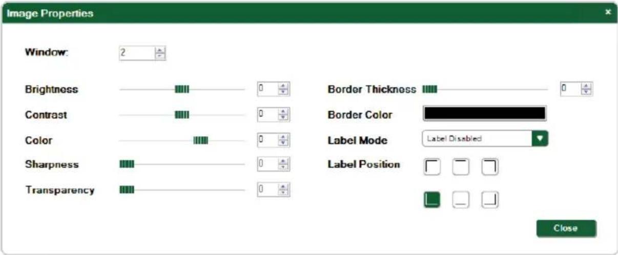
Figure 10: Image Properties Window
2. Select the required window to modify.
- Modify the properties as required.
- Click Close.
The image properties for the selected window are set.
| Field | Description |
| Window | Selects the window for which you want to change the properties |
| Brightness | Sets the brightness of the window |
| Contrast | Sets the Contrast of the window |
| Color | Sets the color of the window |
| Sharpness | Sets the sharpness of the window |
| Transparency | Sets the transparency of the window |
| Border Thickness | Sets the border width of the window |
| Border Color | Sets the border color of the window |
| Label Mode | Enables/disable the border label and adjusts the label properties, (Label Disabled, Black Window Label, White Window Label, Black Video Input Label, White Input Video Label) |
| Label Position | Sets the position of the label in the border, (Top left, top middle, top right, bottom left, bottom middle, bottom right) |
8.2.3 Setting the Output Advanced Properties
You can set the output properties, such as, HD and SD formats, and output when there is no signal input.
To modify the image properties:
- From the Menu bar, click Display > Advanced Properties.
The Advanced Properties window appears as shown in Figure 11.

Figure 11: Advanced Properties Window
2. Modify the properties as required.
- Click Close.
The output properties are set.
| Field | Description |
| Output Standard Mode | Selects the output between Forced Output Standard and Auto Defined by DVI Background Input |
| Analog HD Output Format | Sets analog HD output format, (RGBHV, RGBS, RGsB, YUV bi-sync, YUV tri-sync) |
| Analog SD Output Format | Sets the analog SD output format, (YUV SD, 3 outputs CVBS, YC and one CVBS) |
| No Signal Handle Mode | Sets the output when no input is present, (freeze last image, Blue screen, Black screen, Remove window) |
| LCD Brightness | Sets the brightness of the LCD backlighting |
| Sleep Mode Brightness | Sets the brightness of the LCD backlighting when the device is in sleep mode |
8.2.4 Updating the Firmware
To update the firmware:
- Download the latest firmware file from http:www.kramerav.com.
- Click Device > Firmware Upgrade.
- Browse to the firmware file that you downloaded.
- Click Upload.
The device firmware is loaded.

Note: Do not interrupt the uploading process or the device may be rendered inoperable.
- When the process is complete, reboot the device.
8.2.5 Changing the Device Details
From this window you can change the device name and its IP communication parameters.
To change the device details:
- From the Menu bar, click on Device.
The Device Details window appears as shown in Figure 12.

Figure 12: Device Details Window
- Modify the parameters as required. For each modified parameter, click Set Value.
- Click Close.
Note: If you modify any of the IP parameters you must reconnect to the device with the new parameters.
8.2.6 Displaying the MV-5 Software Version Number
To display the MV-5 Software version number:
- From the Menu bar, click About.
The About MV-5 Multiviewer Controller window appears as shown in Figure 13.

Figure 13: About MV-5 Window
- Click OK to close the window.
8.3 The Quick Access Toolbar
The Quick Access Toolbar is shown in Figure 14 and described in the table below.


Disconnect


Figure 14: Quick Access Toolbar
| Feature | Description |
 | Open an existing project |
 | Save the current project |
  | Connects to and disconnects from the device (seeSection 8.3.1) |
  | Press Take to enable multiple off-line changes to be made. Press Update to implement the changes (seeSection 8.4.5) |
  | Freezes and releases the top window |
  | Sets the visibility of the active window |
 | Sets the window zoom parameters |
 | Sets the chroma key properties |
Figure 15: Quick Access Toolbar Icons
8.3.1 Connecting to the Device
To connect to the device:
1. Click the Connect button.
The Connection Method window shown in Figure 16 appears.
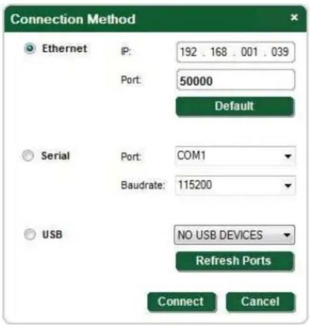
Figure 16: Connection Method Window
2. Select the required method of connection radio button:
For Ethernet, enter the IP address and Port number of the device. To set the default IP address and Port number, press the Default button
For a serial connection, select the required Com port and baud rate from the drop-down lists
- For a USB connection, select the required USB connection from the drop-down list
3. Click Connect.
If the connection is successful, the main window shown in Figure 8 appears. If the connection is not successful, a Timeout error message appears.
8.4 Using the MV-5 Multiviewer Software
8.4.1 Windows Position
The windows can be manually manipulated in size and position in the Window Position area.
Windows Position
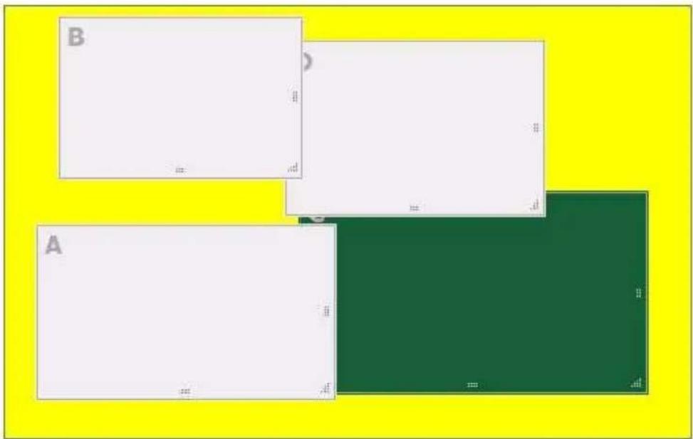
Figure 17: Windows Position
To change the size of a window:
- Click, hold and drag the required window handle
To change the position of a window:
- Click, hold and drag anywhere in the window
8.4.2 Window and Input Buttons
The switching configuration can be modified by clicking on the Windows and Inputs buttons.

flowchart
graph TD
    A["1"] -->|Switch Windows| B["A WINDOW 1\nDVI INPUT 3"]
    C["2"] --> B
    D["3"] --> B
    E["4"] --> B
    B --> F["B WINDOW 2\nSDI INPUT 3"]
    B --> G["C WINDOW 3\nDVI INPUT 2"]
    B --> H["D WINDOW 4\nANALOG HD IN 1"]
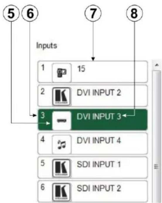
Figure 18: Switch Buttons
| # | Feature | Function |
| 1 | A | Layer identifier (A to D) |
| 2 | WINDOW Buttons (A to D) | Click to select a window to assign to an input (see Section 8.4.6) |
| 3 | 1 | Input number (1 to 4) |
| 4 | DVI INPUT 3 | Currently selected input for this window |
| 5 | DVD Icon | The input icon assigned to this window (see Section 8.4.8) |
| 6 | 3 | Input number |
| 7 | Input Button | Click to select one of the 16 inputs |
| 8 | DVI INPUT 3 | The input label assigned to this button (see Section 8.4.4) |
8.4.3 Device Status
The device status can be one of the following states:
- Online—the device is updated in real-time by the application, and changes to settings on the device are reflected almost immediately in the software
- Online in take mode—changes made in the application are only implemented on the device when the Update button is pressed
8.4.4 Changing the Layer Order
You can modify the order in which the windows are arranged. The top layer is on the right and the bottom layer on the left. In Figure 19 layer A is on top and layer C is at the bottom.
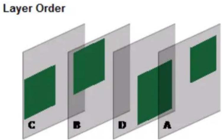
Figure 19: Layer Order
To change the window layer order:
- Click and hold on the layer that you want to move.
- Drag the layer to the right or left into the required position and release. The layer is placed in the required position.
8.4.5 Implementing Multiple Actions At Once
To implement multiple actions at once:
-
Press the Take button to put the device in off-line mode. The button changes to the Update button and the device is in off-line mode.
-
Initiate the required actions, such as, switching and layer order changes.
-
Press the Update button. The button changes to the Take button and all actions are executed.
8.4.6 Switching an Input to a Window
To switch an input to a window:
1. Click on the required window button.
The window is selected, promoted to the top layer (if it wasn't already) and the button changes to a solid color as shown in Figure 20.


Figure 20: Switching an Input to a Window
2. Click on the required Inputs button.
The input is assigned to the previously selected window and the button changes to a solid color.
8.4.7 Changing a Window Setup
To change a window setup:
- Right-click on the relevant Windows button.
- The Window Setup window appears as shown in Figure 21.
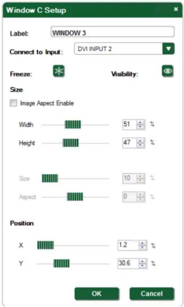
Figure 21: Windows Setup Window
- From the Connect to Input drop-down list, select the required input.
- Click the Freeze icon to freeze this window.
-
Click the Visibility icon to modify the visibility of this window.
-
In the Size fields, adjust the width and height percentage size of the window relative to the full image.
This adjusts the size of this window.
Note: Checking the Image Aspect Enable box locks the width and height settings. With this box checked you can change only the size and aspect ratio of the image.
-
If the Image Aspect Enable box is checked, adjust the size and aspect ratio percentages of the image.
-
In the Position fields, enter the x and y position percentage for the window relative to the original position.
This adjusts the position of this window.
- Click OK.
The Window setup is changed.
8.4.8 Changing Input Button Properties
To change the properties of an input button:
- Right-click on the relevant input button.
The Input Properties window appears as shown in Figure 22.
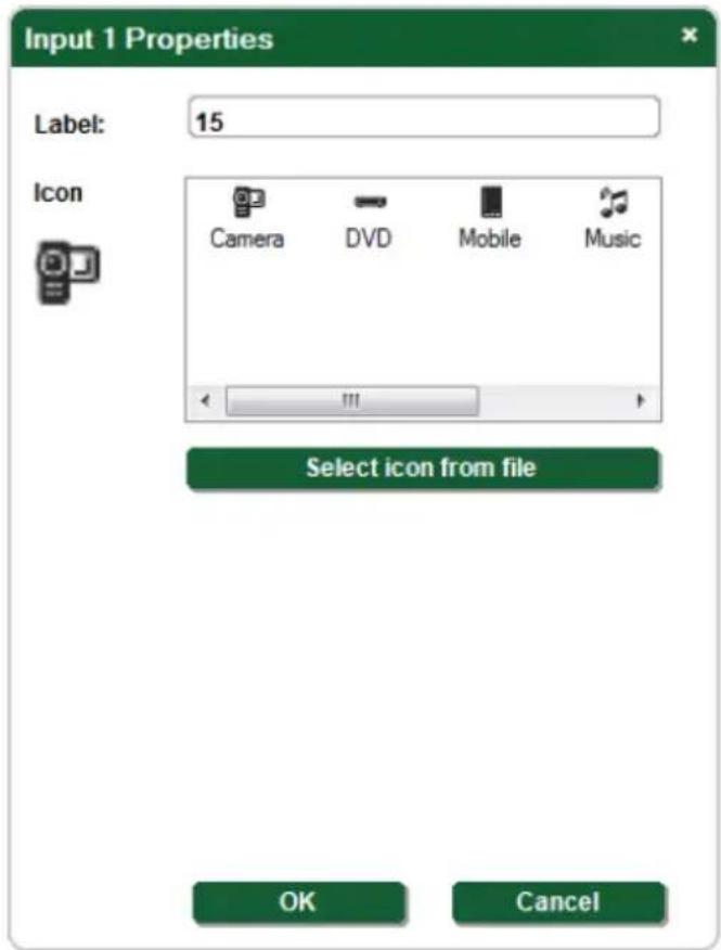
Figure 22: Input Button Properties Window
-
In the Label text box, enter the required button label. Note: The label is limited to 10 characters.
-
Select the required icon from the list or click on the Select icon from file button and browse to the required file. The icon image should be no larger than 32 x 32 pixels and one of the following formats: BMP, JPG, GIF, PNG, TIF, ICO.
-
Click OK. The input button characteristics are changed.
9 Upgrading the Firmware
The firmware can be uploaded either using the Web pages (see Section 8.2.4) or by using the K-Upload Software. The instructions for using the K-Upload
Software can be found in the "Upgrading the MV-5 Firmware Using the K-Upload Software" document available for download from http://www.kramerav.com.
10 Technical Specifications
| INPUTS: | 4 RGB/Component HD on 20 BNC connectors12 Analog SD on BNC connectors (12CV / 6YC / 3YCBCR)5 DVI-D (1 as a dedicated background) on 5 DVI-I Molex 24-pin(F) connectors4 SDI on 4 BNC connectors |
| OUTPUTS: | 1 RGB/Component HD on 5 BNC connectors1 DVI-D on a DVI-I Molex 24-pin (F) connector2 SDI on 2 BNC connectors |
| JITTER: | Better than 0.2UI |
| DATA RATE: | Up to 2.97Gbps |
| HDMI BANDWIDTH: | Up to 6.75Gbps data rate (2.25Gbps per graphic channel) |
| COMPLIANCE WITH HDMI STANDARD: | HDCP (DVI inputs/outputs) |
| SUPPORTED OUTPUT RESOLUTIONS: | 480i/60, 576i/50, 720p/50, 720p/59, 720p/60, 1080i/50,1080i/59, 1080i/60, 1080p/23, 1080p/24, 1080p/25, 1080p/29,1080p/30, 1080p/50, 1080p/59, 1080p/60, 1080psf/23,1080psf/24, 1080psf/25, 1080psf/29, 1080psf/30, 640x480/60,640x480/72, 640x480/75, 640x480/85, 800x600/60,800x600/72, 800x600/75, 800x600/85, 1024x768/60,1024x768/70, 1024x768/75, 1024x768/85, 1152x864/75,1280x768/60rducBL, 1280x768/60, 1280x768/75, 1280x800/60,1280x960/60, 1280x1024/60, 1280x1024/75, 1360x768/60,1366x768/60, 1400x1050/60rducBL, 1400x1050/60,1400x1050/75, 1440x900/60rducBL, 1440x900/60,1440x900/75, 1440x900/85, 1600x1200/60,1680x1050/60rducBL, 1680x1050/60, 1920x1200/60rducBL |
| POWER CONSUMPTION: | 100-240V AC, 50/60Hz, 57VA |
| CONTROLS: | Front panel buttons, RS-232, Ethernet |
| OPERATING TEMPERATURE: | 0^ to +40^ ( 32^ to 104^ ) |
| STORAGE TEMPERATURE: | -40^ to +70^ ( -40^ to 158^ ) |
| HUMIDITY: | 10% to 90%, RHL non-condensing |
| DIMENSIONS: | 19" x 9.45" x 2U (W, D, H) |
| WEIGHT: | 2.8kg (6.17lbs) approx. |
| INCLUDED ACCESSORIES: | Power cord, rack "ears" |
| Specifications are subject to change without notice at http://www.kramerav.com | |
11 Default Communication Parameters
| RS-232 | |
| Baud Rate: | 115,200 |
| Data Bits: | 8 |
| Stop Bits: | 1 |
| Parity: | None |
| Command Format: | ASCII |
| Protocol example (Output 1 to Input 1): | #AV 1>1 |
| Ethernet | |
| IP Address: | 192.168.1.39 |
| TCP Port #: | 5000 |
| UDP Port #: | 50000 |
12 Default EDID
The MV-5 has a non-modifiable, preprogrammed EDID stored on each input.
Monitor
Model name...... MV-5
Manufacturer..... KMR
Plug and Play ID..... KMR1200
Serial number...... 505-708980100
Manufacture date...... 2011, ISO week 255
Filter driver...... None
EDID revision...... 1.3
Input signal type...... Digital
Color bit depth...... Undefined
Display type..... RGB color
Screen size.... 520 x 320 mm (24.0 in)
Power management...... Standby, Suspend, Active off/sleep
Extension blocs..... 1 (Reserved - 0x00)
DDC/CI...... Not supported
Color characteristics
Default color space..... Non-sRGB
Display gamma...... 2.20
Red chromaticity..... Rx 0.674 - Ry 0.319
Green chromaticity..... Gx 0.188 - Gy 0.706
Blue chromaticity..... Bx 0.148 - By 0.064
White point (default).... Wx 0.313 - Wy 0.329
Additional descriptors... None
Timing characteristics
Horizontal scan range.... 30-83kHz
Vertical scan range..... 56-76Hz
Video bandwidth..... 170MHz
CVT standard...... Not supported
GTF standard...... Not supported
Additional descriptors... None
Preferred timing...... Yes
Native/preferred timing.. 1280x720p at 60Hz (16:10)
Modeline...... "1280x720" 74.250 1280 1390 1430 1650 720 725 730 750 +hsync +vsync
Standard timings supported
720 x 400p at 70Hz - IBM VGA
640 x 480p at 60Hz - IBM VGA
640 x 480p at 75Hz - VESA
800 x 600p at 60Hz - VESA
800 x 600p at 75Hz - VESA
1024 x 768p at 60Hz - VESA
1024 x 768p at 75Hz - VESA
1280 x 1024p at 75Hz - VESA
1280 x 1024p at 60Hz - VESA STD
1600 x 1200p at 60Hz - VESA STD
1152 x 864p at 75Hz - VESA STD
Report information
Date generated...... 14-Jul-14
Software revision..... 2.60.0.972
Data source...... Real-time 0x0100
Operating system...... 6.1.7601.2.Service Pack 1
Raw data
00,FF,FF,FF,FF,FF,FF,00,2D,B2,00,12,01,01,01,01,FF,15,01,03,80,34,20,78,EA,B3,25,AC,51,30,B4,26,
10,50,54,A5,4B,00,81,80,A9,40,71,4F,01,01,01,01,01,01,01,01,01,01,01,01,1D,00,72,51,D0,1E,20,6E,28,
55,00,07,44,21,00,00,1E,00,00,00,FF,00,35,30,35,2D,37,30,38,39,38,30,31,30,30,00,00,00,FC,00,4D,
56,2D,35,00,00,00,00,00,00,00,00,00,00,00,00,FD,00,38,4C,1E,53,11,00,0A,20,20,20,20,20,20,01,C2
13 Kramer Protocol 3000
The MV-5 can be operated using serial commands from a PC, remote controller or touch screen using the Kramer Protocol 3000.
This section describes:
• Kramer Protocol 3000 syntax (see Section 13.1)
• Kramer Protocol 3000 commands (see Section 13.2)
13.1 Kramer Protocol 3000 Syntax
13.1.1 Host Message Format
| Start | Address (optional) | Body | Delimiter |
| # | device_id@ | Message | CR |
13.1.2 Simple Command
Command string with only one command without addressing:
| Start | Body | Delimiter |
| # | Command SP Parameter_1,Parameter_2,... | CR |
13.1.3 Command String
Formal syntax with commands concatenation and addressing:
| Start | Address | Body | Delimiter |
| # | device_id@ | Command_1 Parameter1_1,Parameter1_2,...|Command_2 Parameter2_1,Parameter2_2,...|Command_3 Parameter3_1,Parameter3_2,...|... | CR |
13.1.4 Device Message Format
| Start | Address (optional) | Body | delimiter |
| ~ | device_id@ | Message | CR LF |
13.1.5 Device Long Response
Echoing command:
| Start | Address (optional) | Body | Delimiter |
| ~ | device_id@ | Command SP [Param1,Param2 ...] result | CR LF |
CR = Carriage return (ASCII 13 = 0x0D)
LF = Line feed (ASCII 10 = 0x0A)
SP = Space (ASCII 32 = 0x20)
13.1.6 Command Terms
Command
A sequence of ASCII letters ('A'-'Z', 'a'-'z' and '-').
Command and parameters must be separated by at least one space.
Parameters
A sequence of alphanumeric ASCII characters ('0'-9', 'A'-Z', 'a'-z' and some special characters for specific commands). Parameters are separated by commas.
Message string
Every command entered as part of a message string begins with a message starting character and ends with a message closing character.
Note: A string can contain more than one command. Commands are separated by a pipe ( ' |' ) character.
Message starting character
'#' – For host command/query
'\~' – For device response
Device ID (Optional, for K-NET)
K-NET Device ID followed by '@'
Query sign
'?' follows some commands to define a query request.
Message closing character
CR – For host messages; carriage return (ASCII 13)
CRLF – For device messages; carriage return (ASCII 13) + line-feed (ASCII 10)
Command chain separator character
When a message string contains more than one command, a pipe ('|') character separates each command.
Spaces between parameters or command terms are ignored.
13.1.7 Entering Commands
You can directly enter all commands using a terminal with ASCII communications software, such as HyperTerminal, Hercules, etc. Connect the terminal to the serial or Ethernet port on the Kramer device. To enter CR press the Enter key.
( LF is also sent but is ignored by command parser).
For commands sent from some non-Kramer controllers like Crestron, some characters require special coding (such as, /X##). Refer to the controller manual.
13.1.8 Command Forms
Some commands have short name syntax in addition to long name syntax to allow faster typing. The response is always in long syntax.
13.1.9 Chaining Commands
Multiple commands can be chained in the same string. Each command is delimited by a pipe character ("|"). When chaining commands, enter the message starting character and the message closing character only once, at the beginning of the string and at the end.
Commands in the string do not execute until the closing character is entered.
A separate response is sent for every command in the chain.
13.1.10 Maximum String Length
64 characters
13.2 Kramer Protocol 3000 Commands
13.2.1 Common Commands
| Command | Description |
| # | Protocol handshaking |
| BUILD-DATE? | Read device build date |
| ETH-PORT | Change protocol Ethernet port |
| ETH-PORT? | Query protocol Ethernet port |
| FACTORY | Reset to factory default configuration |
| HELP | List of commands |
| LOCK-FP | Lock front panel |
| LOCK-FP? | GET Lock front panel |
| MACH-NUM | Set Machine number |
| MODEL? | Read device model |
| NAME | Set machine (DNS) name |
| NAME? | Query machine (DNS) name |
| NAME-RST | Reset machine name to factory default (DNS) |
| NET-DHCP | Set DHCP mode |
| NET-DHCP? | Query DHCP mode |
| NET-GATE | Set Gateway |
| NET-GATE? | Query Gateway |
| NET-IP | Set IP address |
| NET-IP? | Query IP address |
| NET-MAC? | Query MAC address |
| NET-MASK | Set subnet mask |
| NET-MASK? | Query subnet mask |
| PROT-VER? | Read device protocol version |
| PRST-RCL | Read saved preset list (see Note below) |
| RESET | Reset device |
| SN? | Read device serial number |
| UPGRADE | Execute firmware upgrade |
| VERSION? | Read device firmware version |
13.2.2 Device-Specific Commands
Set Command syntax
Y Control_Type=0, Function#, Param
For example:
Y 0,212,1
Device response:
\~id=01Y Control_Type=0,Function#,Param
For example:
\~01@Y 0,212,1
Get Command syntax
Y Control_Type=1, Function
For example:
Y 1,200
Device response:
\~id=01Y Control_Type=1, Function, Param
For example:
\~01@Y 1,200,3
The following table lists the MV-5 "Y commands". If a parameter in the table is given as multidimensional vector (for example, IN_FRMT[4] - has the dimension = 4), this signifies that there are four different parameters each of which reflect a state of the same feature for different inputs or different windows. In order to address the required input or window, one more parameter must be added to the "Y command"- the fourth for "Set Command" and third for "Get Command". For example "#Y 0,103,25,2" signifies "Set Command, function = 103 (Pixel Latch Phase = PX_PHS[2]), Value = 25, only for Analog HD INPUT # 3 (as here additional parameter A = 2, this corresponds to INPUT # = A + 1). Another example: "#Y 0,303,-50,0" - signifies "Set Command, function = 303 (Window H size = HSZ_H[0]), Value = -50, only for WINDOW # 1 (as here additional parameter A = 0, this corresponds to WINDOW # = A + 1). The Notes column indicates whether the additional parameter is related to a window or to an input.
| Description | Function # | Parameter | Value | Notes |
| Analog HD Input format | 100 | IN_FRMT[4] | 0 | RGBHV (additional parameter defines HD input) |
| 1 | RGBS | |||
| 2 | RGsB | |||
| 3 | YUV (bi-sync or tri-sync auto definition) | |||
| Horizontal start pixel | 101 | H_STRT[4] | [-100:+100] | Additional parameter defines analog HD input |
| Vertical start line | 102 | V_STRT[4] | [-50:+50] | Additional parameter defines analog HD input |
| Pixel latch phase | 103 | PX_PHS[4] | [0:31] | Additional parameter defines analog HD input |
| SD button input assignment | 104 | SDBTN[4] | 0 | Analog CV1 input |
| 1 | Analog CV2 input | |||
| 2 | Analog CV3 input | |||
| 3 | Analog CV4 input | |||
| 4 | Analog CV5 input | |||
| 5 | Analog CV6 input | |||
| 6 | Analog CV7 input | |||
| 7 | Analog CV8 input | |||
| 8 | Analog CV9 input | |||
| 9 | Analog CV10 input | |||
| 10 | Analog CV11 input | |||
| 11 | Analog CV12 input | |||
| 12 | Analog YC1 input | |||
| 13 | Analog YC2 input | |||
| 14 | Analog YC3 input | |||
| 15 | Analog YC4 input | |||
| 16 | Analog YC5 input | |||
| 17 | Analog YC6 input | |||
| 18 | Analog YUV1 input | |||
| 19 | Analog YUV2 input | |||
| 20 | Analog YUV3 input | |||
| DVI inputs HDCP capability | 105 | HDCP_IN[5] | 0 | DVI input# is HDCP capable |
| 1 | DVI input# is HDCP non-capable Additional parameter defines DVI Input. HDCP_IN[4] – for DVI background input | |||
| Output Video Resolution | 200 | OUT_RSL | 0 | 480i/60 |
| 1 | 576i/50 | |||
| 2 | 720p/50 | |||
| 3 | 720p/59 | |||
| 4 | 720p/60 | |||
| 5 | 1080i/50 | |||
| 6 | 1080i/59 | |||
| 7 | 1080i/60 | |||
| 8 | 1080p/23 | |||
| 9 | 1080p/24 | |||
| 10 | 1080p/25 | |||
| 11 | 1080p/29 | |||
| 12 | 1080p/30 | |||
| 13 | 1080p/50 | |||
| 14 | 1080p/59 | |||
| 15 | 1080p/60 | |||
| 16 | 1080sf/23 | |||
| 17 | 1080sf/24 | |||
| 18 | 1080sf/25 | |||
| 19 | 1080sf/29 | |||
| 20 | 1080sf/30 | |||
| 21 | 640x480/60 | |||
| 22 | 640x480/72 | |||
| 23 | 640x480/75 | |||
| 24 | 640x480/85 | |||
| 25 | 800x600/60 | |||
| 26 | 800x600/72 | |||
| 27 | 800x600/75 | |||
| 28 | 800x600/85 | |||
| 29 | 1024x768/60 | |||
| 30 | 1024x768/70 | |||
| 31 | 1024x768/75 | |||
| 32 | 1024x768/85 | |||
| 33 | 1152x864/75 | |||
| 34 | 1280x768/60 reduced blanking | |||
| 35 | 1280x768/60 | |||
| 36 | 1280x768/75 | |||
| 37 | 1280x800/60 | |||
| 38 | 1280x960/60 | |||
| 39 | 1280x960/85 | |||
| 40 | 1280x1024/60 | |||
| 41 | 1280x1024/75 | |||
| 42 | 1360x768/60 | |||
| 43 | 1366x768/60 | |||
| 44 | 1400x1050/60 reduced blanking | |||
| 45 | 1400x1050/60 | |||
| 46 | 1400x1050/75 | |||
| 47 | 1440x900/60 reduced blanking | |||
| 48 | 1440x900/60 reduced blanking | |||
| 49 | 1440x900/75 | |||
| 50 | 1440x900/85 | |||
| 51 | 1600x1200/60 | |||
| 52 | 1680x1050/60 reduced blanking | |||
| 53 | 1680x1050/60 | |||
| 54 | 1920x1200/60 reduced blanking | |||
| Top Layer fit in the screen | 201 | CROP_PVW | 0 | Normal windows size and position |
| 1 | Top Layer window Image is fit in the screen | |||
| Cropping Preview | 2 | The cropping border arises | ||
| Analog HD output format | 202 | OUT_HD_FRMT | 0 | RGBHV |
| 1 | RGBS | |||
| 2 | RGsB | |||
| 3 | YUV bi-sync | |||
| 4 | YUV tri-sync | |||
| Analog SD output format | 203 | OUT_SD_FRMT | 0 | YUV SD |
| 1 | Three outputs CVBS | |||
| 2 | YC and one CVBS | |||
| Background image source | 204 | BG_MODE | 0 | Colored background field |
| 1 | DVI background input | |||
| Background color RED | 205 | BG_RED | [0:255] | Active only if BG_MODE = 0 |
| Background color GREEN | 206 | BG_GREEN | [0:255] | Active only if BG_MODE = 0 |
| Background color BLUE | 207 | BG_BLUE | [0:255] | Active only if BG_MODE = 0 |
| Background freeze | 208 | BG_FRZ | 0 | No freeze background |
| 1 | Freeze background | |||
| Analog Output Sync mode Only For 720p, 1080i, 1080p in case of RGBHV Output Format | 209 | OUT_SNC_MODE | 0 | Analog output sync meets the CEA Standard RGBHV format (H - pos, V - pos) |
| 1 | INVERS1: H- neg, V - neg | |||
| 2 | INVERS2: H- neg, V - neg, H advanced | |||
| RGB Out Hsync position | 210 | OUT_H_POS | [-75;75] | H sync position (for RGBHV, RGBS, RGsB) |
| RGB Out Vsync position | 211 | OUT_V_POS | [-1;7] | V sync position (for RGBHV, RGBS, RGsB) |
| DVI OUTPUT HDCP MODE | 212 | HDCP_OUT | 0 | DVI Output HDCP "FOLLOW INPUT" |
| 1 | DVI Output HDCP "FOLLOW OUTPUT" | |||
| 2 | HDCP on Output "ON" | |||
| 3 | HDCP on Output "OFF" | |||
| DVI OUTPUT HDCP STATUS | 213 | OUT_STATUS | 0 | Output forced to non-encrypted (NO HDCP) |
| 1 | MV-5 tries to set HDCP link, but acceptor don't support HDCP. Encryption turn OFF | |||
| 2 | HDCP active (monitor supports HDCP) | |||
| 3 | DVI output HDCP is ACTIVE, but SDI and Analog outputs are disabled | |||
| Window input source SELECT | 300 | WND_INP[4] | 0 | DVI1 input (additional parameter defines a window) |
| 1 | DVI2 input | |||
| 2 | DVI3 input | |||
| 3 | DVI4 input | |||
| 4 | SDI1 input | |||
| 5 | SDI2 input | |||
| 6 | SDI3 input | |||
| 7 | SDI4 input | |||
| 8 | Analog HD1 input | |||
| 9 | Analog HD2 input | |||
| 10 | Analog HD3 input | |||
| 11 | Analog HD4 input | |||
| 12 | Analog SD1 button | |||
| 13 | Analog SD2 button | |||
| 14 | Analog SD3 button | |||
| 15 | Analog SD4 button | |||
| Window Input Resolution (READ ONLY) | 301 | INP_RSL[5] | 0 | 480i/60 INP_RSL[4] - background |
| 1 | 576i/50 | |||
| INP_RES[0] - window 1 | 2 | 720p/50 | ||
| INP_RES[1] - window 2 | 3 | 720p/59 | ||
| INP_RES[2] - window 3 | 4 | 720p/60 | ||
| INP_RES[3] - window 4 | 5 | 1080i/50 | ||
| INP_RES[4] - reflects background input status | 6 | 1080i/59 | ||
| 7 | 1080i/60 | |||
| 8 | 1080p/23 | |||
| 9 | 1080p/24 | |||
| 10 | 1080p/25 | |||
| 11 | 1080p/29 | |||
| 12 | 1080p/30 | |||
| 13 | 1080p/50 | |||
| 14 | 1080p/59 | |||
| 15 | 1080p/60 | |||
| 16 | 1080sf/23 | |||
| 17 | 1080sf/24 | |||
| 18 | 1080sf/25 | |||
| 19 | 1080sf/29 | |||
| 20 | 1080sf/30 | |||
| 21 | 640x480/60 | |||
| 22 | 640x480/72 | |||
| 23 | 640x480/75 | |||
| 24 | 640x480/85 | |||
| 25 | 800x600/60 | |||
| 26 | 800x600/72 | |||
| 27 | 800x600/75 | |||
| 28 | 800x600/85 | |||
| 29 | 1024x768/60 | |||
| 30 | 1024x768/70 | |||
| 31 | 1024x768/75 | |||
| 32 | 1024x768/85 | |||
| 33 | 1152x864/75 | |||
| 34 | 1280x768/60 reduced blanking | |||
| 35 | 1280x768/60 | |||
| 36 | 1280x768/75 | |||
| 37 | 1280x800/60 | |||
| 38 | 1280x960/60 | |||
| 39 | 1280x960/85 | |||
| 40 | 1280x1024/60 | |||
| 41 | 1280x1024/75 | |||
| 42 | 1360x768/60 | |||
| 43 | 1366x768/60 | |||
| 44 | 1400x1050/60 reduced blanking | |||
| 45 | 1400x1050/60 | |||
| 46 | 1400x1050/75 | |||
| 47 | 1440x900/60 reduced blanking | |||
| 48 | 1440x900/60 reduced blanking | |||
| 49 | 1440x900/75 | |||
| 50 | 1440x900/85 | |||
| 51 | 1600x1200/60 | |||
| 52 | 1680x1050/60 reduced blanking | |||
| 53 | 1680x1050/60 | |||
| 54 | 1920x1200/60 reduced blanking | |||
| 55 | UNIDENTIFIED INPUT SIGNAL | |||
| 56 | NO INPUT SIGNAL | |||
| Window priority definition | 302 | W_PRIO[4] | 0 | Window disappears |
| 1 | Upper (top) layer window | |||
| 2 | Window after upper layer | |||
| 3 | Next window | |||
| 4 | Lower layer window, can be overlapped by all others | |||
| Window H size | 303 | WSZ_H[4] | [-90:0] | If WSZ_H = 0 - window width fit in the screen 100%If WSZ_H = -90 - window width = 10% of screen width. Step = 1% |
| Window V size | 304 | WSZ_V[4] | [-90:0] | If WSZ_V = 0 - window height fit in the screen 100%;If WSZ_V = -90 - window height = 10% screen height.Step = 1% |
| Window aspect enable | 305 | W_ASP_EN[4] | 0 | H and V window sizes are defined independentlyby WSZ_H and WSZ_V |
| 1 | Parameter WSZ_H affects simultaneously H and V window size, but the relation between H and V sizes is defined by next parameter: WIN_ASP | |||
| Window Aspect ratio | 306 | WIN_ASP[4] | [-75:75] | If WIN_ASP = 0 - window aspect is equal to original screen aspect (100%), namely:Real window WIDTH(%) = WSZ_H + 100;HEIGHT(%) = WSZ_H + 100If WIN_ASP > 0 then as above, window WIDTH(%) = WSZ_H + 100, but the height is reduced accordingly the formula :HEIGHT(%)=(WSZ_H+100) * 100 / /(WIN_ASP + 100) (window is like letterbox)If WIN_ASP < 0 then window HEIGHT(%) = WSZ_H + 100, but the width is reduced accordingly the formula :WIDTH(%) =(WSZ_H+100) * (100 + WIN_ASP) / 100(window is like pillarbox) |
| Window H position | 307 | WPOS_H[4] | [0:1000] | Defines X coordinate of top left corner of window normalized relatively screen width (Step = 0.1%)represented in percent of screen width * 10 |
| Window V position | 308 | WPOS_V[4] | [0:1000] | Defines Y coordinate of top left corner of window normalized relatively screen height. Step = 0.1%represented in percent of screen height * 10 |
| Image H size | 309 | IMSZ_H[4] | [0:900] | Defines H size of image relatively window H size(i.e. H ZOOM) Step = 1% If IMSZ_H = 0 then image is exactly fits to window width.If IMSZ_H > 0 then real IM_WIDTH(%) = (IMSZ_H + 100) window WIDTHImage is cropped. If IMSZ_H = 900, then set maximal H ZOOM = 1000% |
| Image V size | 310 | IMSZ_V[4] | [0:900] | Defines V size of image relatively window V size(i.e. V ZOOM) Step = 1% If IMSZ_V = 0 then image is exactly fits to window height.If IMSZ_V > 0 then realIM_HEIGHT(%)=(IMSZ_V + 100) In this case the image is cropped. |
| Image aspect enable | 311 | IM_ASP_EN[4] | 01 | H and V image sizes are defined independentlyby IMSZ_H and IMSZ_VParameter IMSZ_H affects simultaneouslyH and V image size, but the relation betweenH and V sizes is defined by parameter: IM_ASP |
| Image Aspect ratio | 312 | IM_ASP[4] | [-50:100] | If IM_ASP = 0 - image aspect is equal tooriginal input image aspect (100%)If IM_ASP = -50 then aspect= 0.5 of originalIf IM_ASP = +100 then aspect = 2.0 of original |
| Image position H relativelywindow (H panorama) | 313 | IMPOS_H[4] | [0:1000] | Defines shift of image to the left with croppingof image left side, measured in percent of original image width.Step = 0.1%.Allows image H panorama in case of ZOOM |
| Image position V relativelywindow (Vertical panorama) | 314 | IMPOS_V[4] | [0:1000] | Defines shift of image to the bottom with cropping of image bottom side, measuredin percent of original image height.Step = 0.1%.Allows image V panorama in case of ZOOM |
| Window border thickness | 315 | BRD_THKN[4] | [0:20] | If BRD_THKN = 0 then border is OFF |
| Window border color R | 316 | BRD_RED[4] | [0:255] | |
| Window border color G | 317 | BRD_GREEN[4] | [0:255] | |
| Window border color B | 318 | BRD_BLUE[4] | [0:255] | |
| Window image brightness | 319 | BRIGHT[4] | [-50:50] | If BRIGHT = 0 then default brightness (100%) |
| Window image contrast | 320 | CONTRAST[4] | [-50:50] | If CONTRAST = 0 then default contrast (100%) |
| Window image color | 321 | COLOR[4] | [-100:50] | If COLOR = 0 then default color(100%).If SHARP = 0 - no sharpness,if = 15, then max sharpness 150%Step = 10% |
| Window image sharpness | 322 | SHARP[4] | [0:15] | |
| Window freeze image | 323 | FREEZE[4] | 0 | No freeze window image |
| 1 | Freeze window image | |||
| Window keyer enable | 324 | KEYER_EN[4] | 0 | Keyer disable |
| 1 | Keyer enable | |||
| Window keyer threshold Y min | 325 | YKEY_MIN[4] | [0:255] | |
| Window keyer threshold Y max | 326 | YKEY_MAX[4] | [0:255] | |
| Window keyer threshold U min | 327 | UKEY_MIN[4] | [0:255] | |
| Window keyer threshold U max | 328 | UKEY_MAX[4] | [0:255] | |
| Window keyer threshold V min | 329 | VKEY_MIN[4] | [0:255] | |
| Window keyer threshold V max | 330 | VKEY_MAX[4] | [0:255] | |
| Window image transparency | 331 | W_TRNSP[4] | [0:255] | If W_TRNSP = 0 then window image is non-transparent. If W_TRNSP > 0 then the transparency increases and if it equal to 255 then image disappears |
| Window Label Mode | 332 | LBL_MODE[4] | 0 | Label Disabled |
| 1 | BLACK Label attributed to specific window | |||
| 2 | WHITE Label attributed to specific window | |||
| 3 | BLACK Label corresponds to video input | |||
| 4 | WHITE Label corresponds to video input | |||
| Label Position | 333 | LBL_POS[4] | 0 | Bottom left location of label |
| 1 | Bottom center location | |||
| 2 | Bottom right location | |||
| 3 | Top left | |||
| 4 | Top center | |||
| 5 | Top right | |||
| TEST signal | 334 | TEST[4] | 0 | No TEST signal; Input signal is selected for window, if available |
| 1 | COLOR BARS 100% | |||
| 2 | Split COLOR BARS 100% | |||
| 3 | Y RAMP 100 % | |||
| Window input HDCP | 335 | WND_HDCP[5] | 0 | Source is not protected HDCP or this inputis forced to be HDCP incompatible |
| STATUS (READ ONLY) | 1 | Input HDCP is active, but the window is removedor blanked due to HDCP mode settingsInput HDCP is active and this window is present on output image (HDCP monitor only) | ||
| WND_HDCP[4] for background | 2 | |||
| Target file for image saving | 336 | WND_SAVE[4] | 0 | No File |
| 1 | File A | |||
| 2 | File B | |||
| Additional parameter [x] defines a window that contains an image to save | 3 | File C | ||
| 4 | File D | |||
| Source file for image recalling | 337 | WND_RCL[5] | 0 | No File |
| 1 | File A | |||
| 2 | File B | |||
| Additional parameter [x] defines a window that contains the recalled imageIf [x] = 4 then to background | 3 | File C | ||
| 4 | File D | |||
| Recalled Image STATUS | 338 | RCL_ACT[5] | 0 | No recalled File in this window |
| 1 | File A recalled and active | |||
| READ ONLYIf [x] = 4 then | 2 | File B recalled and active | ||
| Status of background | 3 | File C recalled and active | ||
| 4 | File D recalled and active | |||
| No input signal handle mode | 400 | NOSIG_HNDL | 0 | BLACK SCREEN |
| 1 | BLUE SCREN | |||
| 2 | Remove window | |||
| 3 | Freeze last picture | |||
| LCD brightness | 401 | LCD_BRIGHT | [-100:0] | LCD brightness while keyboard activatedIf LCD_BRIGHT=0 - brightness = 100%LCD brightness in sleep mode(after 2 min |
| LCD brightness in sleep | 402 | LCD_SLEEP | [-100:0] | keyboard is non-activated) |
| Panel Lock | 403 | PLOCK | 0 | No Lock FP |
| 1 | Lock Panel |
LIMITED WARRANTY
The warranty obligations of Kramer Electronics for this product are limited to the terms set forth below:
What is Covered
This limited warranty covers defects in materials and workmanship in this product.
What is Not Covered
This limited warranty does not cover any damage, deterioration or malfunction resulting from any alteration, modification, improper or unreasonable use or maintenance, misuse, abuse, accident, neglect, exposure to excess moisture, fire, improper packing and shipping (such claims must be presented to the carrier), lightning, power surges, or other acts of nature. This limited warranty does not cover any damage, deterioration or malfunction resulting from the installation or removal of this product from any installation, any unauthorized tampering with this product, any repairs attempted by anyone unauthorized by Kramer Electronics to make such repairs, or any other cause which does not relate directly to a defect in materials and/or workmanship of this product. This limited warranty does not cover cartons, equipment enclosures, cables or accessories used in conjunction with this product.
Without limiting any other exclusion herein, Kramer Electronics does not warrant that the product covered hereby, including, without limitation, the technology and/or integrated circuit(s) included in the product, will not become obsolete or that such items are or will remain compatible with any other product or technology with which the product may be used.
How Long Does this Coverage Last
Seven years as of this printing; please check our Web site for the most current and accurate warranty information.
Who is Covered
Only the original purchaser of this product is covered under this limited warranty. This limited warranty is not transferable to subsequent purchasers or owners of this product.
What Kramer Electronics will do
Kramer Electronics will, at its sole option, provide one of the following three remedies to whatever extent it shall deem necessary to satisfy a proper claim under this limited warranty:
- Elect to repair or facilitate the repair of any defective parts within a reasonable period of time, free of any charge for the necessary parts and labor to complete the repair and restore this product to its proper operating condition. Kramer Electronics will also pay the shipping costs necessary to return this product once the repair is complete.
- Replace this product with a direct replacement or with a similar product deemed by Kramer Electronics to perform substantially the same function as the original product.
- Issue a refund of the original purchase price less depreciation to be determined based on the age of the product at the time remedy is sought under this limited warranty.
What Kramer Electronics will not do Under This Limited Warranty
If this product is returned to Kramer Electronics or the authorized dealer from which it was purchased or any other party authorized to repair Kramer Electronics products, this product must be insured during shipment, with the insurance and shipping charges prepaid by you. If this product is returned uninsured, you assume all risks of loss or damage during shipment. Kramer Electronics will not be responsible for any costs related to the removal or re-installation of this product from or into any installation. Kramer Electronics will not be responsible for any costs related to any setting up this product, any adjustment of user controls or any programming required for a specific installation of this product.
How to Obtain a Remedy under this Limited Warranty
To obtain a remedy under this limited warranty, you must contact either the authorized Kramer Electronics reseller from whom you purchased this product or the Kramer Electronics office nearest you. For a list of authorized Kramer Electronics resellers and/or Kramer Electronics authorized service providers, please visit our web site at www.kramerelectronics.com or contact the Kramer Electronics office nearest you.
In order to pursue any remedy under this limited warranty, you must possess an original, dated receipt as proof of purchase from an authorized Kramer Electronics reseller. If this product is returned under this limited warranty, a return authorization number, obtained from Kramer Electronics, will be required. You may also be directed to an authorized reseller or a person authorized by Kramer Electronics to repair the product.
If it is decided that this product should be returned directly to Kramer Electronics, this product should be properly packed, preferably in the original carton, for shipping. Cartons not bearing a return authorization number will be refused.
Limitation on Liability
THE MAXIMUM LIABILITY OF KRAMER ELECTRONICS UNDER THIS LIMITED WARRANTY SHALL NOT EXCEED THE ACTUAL PURCHASE PRICE PAID FOR THE PRODUCT. TO THE MAXIMUM EXTENT PERMITTED BY LAW, KRAMER ELECTRONICS IS NOT RESPONSIBLE FOR DIRECT, SPECIAL, INCIDENTAL OR CONSEQUENTIAL DAMAGES RESULTING FROM ANY BREACH OF WARRANTY OR CONDITION, OR UNDER ANY OTHER LEGAL THEORY. Some countries, districts or states do not allow the exclusion or limitation of relief, special, incidental, consequential or indirect damages, or the limitation of liability to specified amounts, so the above limitations or exclusions may not apply to you.
Exclusive Remedy
TO THE MAXIMUM EXTENT PERMITTED BY LAW, THIS LIMITED WARRANTY AND THE REMEDIES SET FORTH ABOVE ARE EXCLUSIVE AND IN LIEU OF ALL OTHER WARRANTIES, REMEDIES AND CONDITIONS, WHETHER ORAL OR WRITTEN, EXPRESS OR IMPLIED. TO THE MAXIMUM EXTENT PERMITTED BY LAW, KRAMER ELECTRONICS SPECIFICALLY DISCLAIMS ANY AND ALL IMPLIED WARRANTIES, INCLUDING, WITHOUT LIMITATION, WARRANTIES OF MERCHANTABILITY AND FITNESS FOR A PARTICULAR PURPOSE. IF KRAMER ELECTRONICS CANNOT LAWFULLY DISCLAIM OR EXCLUDE IMPLIED WARRANTIES UNDER APPLICABLE LAW, THEN ALL IMPLIED WARRANTIES COVERING THIS PRODUCT, INCLUDING WARRANTIES OF MERCHANTABILITY AND FITNESS FOR A PARTICULAR PURPOSE, SHALL APPLY TO THIS PRODUCT AS PROVIDED UNDER APPLICABLE LAW. IF ANY PRODUCT TO WHICH THIS LIMITED WARRANTY APPLIES IS A "CONSUMER PRODUCT" UNDER THE MAGNUSON-MOSS WARRANTY ACT (15 U.S.C.A. §2301, ET SEQ.) OR OTHER APPLICABLE LAW, THE FOREGOING DISCLAIMER OF IMPLIED WARRANTIES SHALL NOT APPLY TO YOU, AND ALL IMPLIED WARRANTIES ON THIS PRODUCT, INCLUDING WARRANTIES OF MERCHANTABILITY AND FITNESS FOR THE PARTICULAR PURPOSE, SHALL APPLY AS PROVIDED UNDER APPLICABLE LAW.
Other Conditions
This limited warranty gives you specific legal rights, and you may have other rights which vary from country to country or state to state.
This limited warranty is void if (i) the label bearing the serial number of this product has been removed or defaced, (ii) the product is not distributed by Kramer Electronics or (iii) this product is not purchased from an authorized Kramer Electronics reseller. If you are unsure whether a reseller is an authorized Kramer Electronics reseller, please visit our Web site at www.kramerelectronics.com or contact a Kramer Electronics office from the list at the end of this document.
Your rights under this limited warranty are not diminished if you do not complete and return the product registration form or complete and submit the online product registration form. Kramer Electronics thanks you for purchasing a Kramer Electronics product. We hope it will give you years of satisfaction.

For the latest information on our products and a list of Kramer distributors, visit our Web site where updates to this user manual may be found.
We welcome your questions, comments, and feedback.
Web site: www.kramerav.com
E-mail: info@kramerav.com





SAFETY WARNING
Disconnect the unit from the power supply before opening and servicin
P/N:

Rev:
- MV-5 5 Channel Multiviewer Quick Start Guide
- Step 1: Check what's in the box
- Step 2: Install the MV-5
- Step 3: Connect the inputs and outputs
- Step 4: Connect the power
- Step 5: Configure the MV-5
- Step 6: Operate the MV-5
- Contents
- Introduction 1
- Getting Started 2
- Overview 4
- Defining the MV-5 5 Channel Multiviewer 6
- Installing in a Rack 10
- Connecting the MV-5 5 Channel Multiviewer 11
- Configuring and Operating the MV-5 Locally 18
- Configuring and Operating the MV-5 Remotely 43
- Upgrading the Firmware 60
- Figures
- Introduction
- Getting Started
- Achieving the Best Performance
- Safety Instructions
- Recycling Kramer Products
- Accessory to Medical Equipment (IEC 60601-1)
- Overview
- Defining the MV-5 5 Channel Multiviewer
- Installing in a Rack
- CAUTION!
- To rack-mount a machine:
- Connecting the MV-5 5 Channel Multiviewer
- To connect the MV-5 5 Channel Multiviewer as illustrated in the example in
- Figure 3:
- Connecting to the MV-5 Using the RS-232 Connection
- To connect to the MV-5 via RS-232:
- Connecting to the MV-5 Using the RS-485 Connection
- Connecting via RS-485
- To connect a device with an RS-485 port to the MV-5:
- Connecting to the MV-5 Using Ethernet
- Connecting the Ethernet Port Directly to a PC
- Connecting the Ethernet Port via a Network Hub or Switch
- Configuring and Operating the MV-5 Locally
- Configuring the MV-5 Using the Menu
- Load Setup Sub-menu
- To load a setup:
- Save Current Setup Sub-menu
- To save the current configuration to a preset:
- Input Configuration Sub-menu
- To set an analog HD input to an input format (for example, Input 2 to format RGBS):
- Output Configuration Sub-menu
- To select the RGsB format for Analog HD output:
- Press Menu.
- To select the DVI input as the background signal:
- Window Configuration Sub-menu
- To set the Window Border Color Red value:
- Input Signal Status Sub-menu
- System Parameters Sub-menu
- Save Image Sub-menu
- To select the image source Window and destination file name:
- Recall Image Sub-menu
- To select the image source File and destination window or background:
- Operating the MV-5 Using the Front Panel Buttons
- This section describes:
- Assigning Inputs to Windows
- Setting Window Layer Priority
- To assign a window a layer priority (for example, Window 3 to priority 1):
- Changing the Size and Aspect Ratio of a Window
- To adjust the horizontal and vertical size of a window separately:
- To change the size of a window and aspect ratio of a window, (for example, Window 2, size 90% and aspect ratio 80%):
- Adjusting the Position of a Window
- To adjust the position of a window:
- Zooming into an Image in a Window
- To adjust the horizontal and vertical Image size (Zoom) within a Window:
- To change the size and aspect ratio of the Image inside a window, (for example, Window 2, Image size 200% and aspect ratio 120%):
- Adjusting the Position of the Image Inside a Window – Panning
- To adjust the position of the image inside a window (panning):
- Freezing and Releasing the Output
- To freeze and release an Image in a Window:
- To freeze and release the background image:
- Locking and Unlocking the Front Panel Buttons
- To lock and unlock the front panel buttons:
- Resetting the Device to Factory Default Configuration
- To reset the device to the factory default configuration:
- Configuring and Operating the MV-5 Remotely
- The Multiviewer Main Window
- The Menu Bar
- Setting the Background Color
- To modify the background color:
- Setting the Image Properties
- To modify the image properties:
- Setting the Output Advanced Properties
- Updating the Firmware
- To update the firmware:
- Changing the Device Details
- To change the device details:
- Displaying the MV-5 Software Version Number
- The Quick Access Toolbar
- Connecting to the Device
- To connect to the device:
- Click the Connect button.
- Select the required method of connection radio button:
- Click Connect.
- Using the MV-5 Multiviewer Software
- Windows Position
- To change the size of a window:
- To change the position of a window:
- Window and Input Buttons
- Device Status
- Changing the Layer Order
- To change the window layer order:
- Implementing Multiple Actions At Once
- To implement multiple actions at once:
- Switching an Input to a Window
- To switch an input to a window:
- Click on the required window button.
- Click on the required Inputs button.
- Changing a Window Setup
- To change a window setup:
- Changing Input Button Properties
- To change the properties of an input button:
- Upgrading the Firmware
- Technical Specifications
- Default Communication Parameters
- Default EDID
- Kramer Protocol 3000
- Kramer Protocol 3000 Syntax
- Host Message Format
- Simple Command
- Command String
- Device Message Format
- Device Long Response
- Command Terms
- Command
- Parameters
- Message string
- Message starting character
- Query sign
- Message closing character
- Command chain separator character
- Entering Commands
- Command Forms
- Chaining Commands
- Maximum String Length
- Kramer Protocol 3000 Commands
- Common Commands
- Device-Specific Commands
- Set Command syntax
- Y 0,212,1
- Get Command syntax
- Y 1,200
- LIMITED WARRANTY
- What is Covered
- What is Not Covered
- How Long Does this Coverage Last
- Who is Covered
- What Kramer Electronics will do
- What Kramer Electronics will not do Under This Limited Warranty
- How to Obtain a Remedy under this Limited Warranty
- Limitation on Liability
- Exclusive Remedy
- Other Conditions
Brand : Kramer
Model : MV-5
Category : Multiviseur vidéo