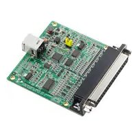
USB-4702-AE - Module multifonction USB Advantech - Free user manual and instructions
Find the device manual for free USB-4702-AE Advantech in PDF.


| Product Type | USB Data Acquisition Module |
| Model | USB-4702-AE |
| Brand | Advantech |
| Analog Input Channels | 16 single-ended or 8 differential |
| Analog Input Resolution | 12-bit |
| Analog Input Range | ±10 V, ±5 V, ±2.5 V, ±1.25 V (software selectable) |
| Analog Output Channels | 2 |
| Analog Output Resolution | 12-bit |
| Analog Output Range | 0 ~ 5 V or 0 ~ 10 V (software selectable) |
| Digital I/O Channels | 16 (8 input, 8 output) |
| Counter/Timer | 1 x 32-bit |
| Data Transfer | USB 2.0 |
| Power Supply | USB powered (no external power needed) |
| Dimensions | 98 x 65 x 30 mm |
| Weight | Approx. 150 g |
| Operating Temperature | 0 to 70 °C |
| Storage Temperature | -20 to 80 °C |
| Software Support | LabVIEW, MATLAB, Visual Studio, DAQNavi |
| Included Accessories | USB cable, software CD, manual |
| Safety | CE, FCC compliant |
Frequently Asked Questions - USB-4702-AE Advantech
User questions about USB-4702-AE Advantech
0 question about this device. Answer the ones you know or ask your own.
Ask a new question about this device
Download the instructions for your Module multifonction USB in PDF format for free! Find your manual USB-4702-AE - Advantech and take your electronic device back in hand. On this page are published all the documents necessary for the use of your device. USB-4702-AE by Advantech.
USER MANUAL USB-4702-AE Advantech
10 kS/s, 12-bit, USB
Multifunction Module
User Manual
Copyright
The documentation and the software included with this product are copyrighted 2009 by Advantech Co., Ltd. All rights are reserved. Advantech Co., Ltd. reserves the right to make improvements in the products described in this manual at any time without notice. No part of this manual may be reproduced, copied, translated or transmitted in any form or by any means without the prior written permission of Advantech Co., Ltd. Information provided in this manual is intended to be accurate and reliable. However, Advantech Co., Ltd. assumes no responsibility for its use, nor for any infringements of the rights of third parties, which may result from its use.
Acknowledgements
Intel and Pentium are trademarks of Intel Corporation.
Microsoft Windows and MS-DOS are registered trademarks of
Microsoft Corp.
All other product names or trademarks are properties of their respective owners.
1st Edition
Printed in Taiwan August 2009
Product Warranty (2 years)
Advantech warrants to you, the original purchaser, that each of its products will be free from defects in materials and workmanship for two years from the date of purchase.
This warranty does not apply to any products which have been repaired or altered by persons other than repair personnel authorized by Advantech, or which have been subject to misuse, abuse, accident or improper installation. Advantech assumes no liability under the terms of this warranty as a consequence of such events.
Because of Advantech's high quality-control standards and rigorous testing, most of our customers never need to use our repair service. If an Advantech product is defective, it will be repaired or replaced at no charge during the warranty period. For out-of-warranty repairs, you will be billed according to the cost of replacement materials, service time and freight. Please consult your dealer for more details.
If you think you have a defective product, follow these steps:
- Collect all the information about the problem encountered. (For example, CPU speed, Advantech products used, other hardware and software used, etc.) Note anything abnormal and list any onscreen messages you get when the problem occurs.
- Call your dealer and describe the problem. Please have your manual, product, and any helpful information readily available.
- If your product is diagnosed as defective, obtain an RMA (return merchandise authorization) number from your dealer. This allows us to process your return more quickly.
- Carefully pack the defective product, a fully-completed Repair and Replacement Order Card and a photocopy proof of purchase date (such as your sales receipt) in a shippable container. A product returned without proof of the purchase date is not eligible for warranty service.
- Write the RMA number visibly on the outside of the package and ship it prepaid to your dealer.
CE
This product has passed the CE test for environmental specifications when shielded cables are used for external wiring. We recommend the use of shielded cables. This kind of cable is available from Advantech. Please contact your local supplier for ordering information.
Technical Support and Assistance
Step 1. Visit the Advantech web site at www.advantech.com/support where you can find the latest information about the product.
Step 2. Contact your distributor, sales representative, or Advantech's customer service center for technical support if you need additional assistance. Please have the following information ready before you call:
- Product name and serial number
- Description of your peripheral attachments
- A complete description of the problem
- The exact wording of any error messages
- Description of your software (operating system, version, application software, etc.)
Document Feedback
To assist us in making improvements to this manual, we would welcome comments and constructive criticism. Please send all such - in writing to: support@advantech.com
Safety Precaution - Static Electricity
Follow these simple precautions to protect yourself from harm and the products from damage.
- To avoid electrical shock, always disconnect the power from your PC chassis before you work on it. Don't touch any components on the CPU card or other cards while the PC is on.
- Disconnect power before making any configuration changes. The sudden rush of power as you connect a jumper or install a card may damage sensitive electronic components.
Contents
Chapter 1 Introduction ...... 2
1.1 Features ...... 2
1.2 Software Overview.... 3
1.2.1 More on the CD 3
Chapter 2 Installation ...... 6
2.1 Unpacking 6
2.2 Driver Installation 7
2.3 Hardware Installation 9
2.4 Hardware Uninstallation 9
Figure 2.1: Unplug or Eject Hardware Dialog .... 10
Figure 2.2:Stop a Hardware device dialog box ..... 10
Chapter 3 Signal Connections .... 12
3.1 Overview 12
3.2 I/O Connectors 12
3.2.1 Pin Assignments 12
Figure 3.1:I/O Connector Pin Assignment .... 12
3.2.2 I/O Connector Signal Description 13
Table 3.1:I/O Connector Signal Description ...... 13
3.3 Analog Input Connections.... 13
3.3.1 Single-ended Channel Connections 13
Figure 3.2: Single-Ended Input Channel Connection ... 14
3.3.2 Differential Input Connections 14
Figure 3.3:Differential Input Channel Connection ..... 15
3.4 Analog Output Connections (Voltage).... 15
Figure 3.4: Analog Output Channel Connections ..... 15
3.5 External Trigger Source Connections 16
3.6 Field Wiring Considerations 16
Appendix A Specifications .... 18
A.1 Analog Input 18
A.2 Analog Output 19
A.3 Non-Isolated Digital Input/Output 19
A.4 Counter 19
A.5 General 19
Introduction
This chapter will provide information on the features of the DAS module, a quick start guide for installation, and some brief information on software and accessories for USB-4702 Module.
Sections include:
- Features
- Software Overview
Chapter 1 Introduction
Thank you for buying the Advantech USB-4702 data acquisition module. The Advantech USB-4702 is a powerful data acquisition (DAS) module for the USB port. It features a unique circuit design and complete functions for data acquisition and control.
1.1 Features
USB-4702 has the most requested measurement & control functions:
- 8 single-ended/4 differential or combination analog input channels
- 12-bit resolution A/D converter, with up to 10kS / s sampling rate
- 8 digital input & 8 digital output channels (TTL Level)
• 2 analog output channels
• 16-bit programmable counter/timer x 1 - Programmable gain for each analog input channel
• Automatic channel/gain scanning - Onboard 512K samples FIFO buffer for AI channels
- Bus-powered
• Supports high-speed USB 2.0
• Auto calibration function - Hot swappable
Note: The USB chip on your system may have a limitation on the number of USB devices it will support. Normally, only five USB-4702 devices can be supported.
Note: The power output of an USB port is 500 mA, while the USB-4702 requires 500 mA (max.). This means that if an USB hub is used, it will need an external power supply to support more than one USB-4702 device.
Advantech offers a rich set of DLL drivers, third-party driver support and application software on the companion CD-ROM to help fully exploit the functions of your device. Advantech's Device Drivers feature a complete I/O function library to help boost your application performance and work seamlessly with development tools such as Visual C++, Visual Basic, Inprise C++ Builder, and Inprise Delphi.
1.2.1 More on the CD
For instructions on how to begin programming in each development tool, Advantech offers some tutorial chapters in the Device Drivers Manual for your reference. Please refer to the corresponding sections in these chapters on the Device Drivers Manual to begin your programming efforts. You can also look at the example source code provided for each programming tool, since they can get you very well oriented.
The Device Drivers Manual can be found on the companion CD-ROM. Alternatively, if you have already installed the Device Drivers on your system, The Device Drivers Manual can be readily accessed through the Start button:
Start/Programs/Advantech Automation/Advantech Device Manager / Device Driver's Manual
After you install the examples, (in CD-ROM:\Example) the example source code can be found under the corresponding installation folder such as the default installation path:
\Program Files\Advantech\ADSAPI\Examples
Installation
Sections include:
- Unpacking
- Driver Installation
- Hardware Installation
• Hardware Uninstallation
Chapter 2 Installation
2.1 Unpacking
After receiving your USB-4702 package, please inspect its contents first. The package should contain the following items:
- USB-4702 Module
• Shielded USB 2.0 Cable (1.8 m) - Companion CD-ROM (DLL driver included)
- User Manual
The USB-4702 Module harbors certain electronic components vulnerable to electrostatic discharge (ESD). ESD could easily damage the integrated circuits and certain components if preventive measures are not carefully paid attention to. Before removing the module from the antistatic plastic bag, you should take following precautions to ward off possible ESD damage:
- Touch the metal part of your computer chassis with your hand to discharge static electricity accumulated on your body. One can also use a grounding strap.
- Make contact between the antistatic bag and ground before opening.
After taking out the module, you should first:
Inspect the module for any possible signs of external damage (loose or damaged components, etc.). If the module is visibly damaged, please notify our service department or our local sales representative immediately. Avoid using a damaged module with your system.
- Avoid physical contact with materials that could hold static electricity such as plastic, vinyl and Styrofoam.
2.2 Driver Installation
We recommend you install the software driver before you install the USB-4702 module into your system, since this will guarantee a smooth installation process.
The 32-bit DLL driver Setup program for the USB-4702 module is included on the companion CD-ROM that is shipped with your module package. Please follow the steps on the following page to install the driver software:

flowchart
graph TD
    A["Insert the DAQ CD"] --> B["Install Device Manager"]
    B --> C["Install Individual Drivers"]
    C --> D{If need}
    D -->|Yes| E["Install Examples & Utilities"]
    D -->|No| F["Finish"]
    E --> G["Examples"]
    G --> H["Install Advance Options"]
    H --> F
For further information on driver-related issues, an online version of the Device Drivers Manual is available by accessing the following path:
Start\Programs\Advantech Automation
\Device Manager\Device Driver's Manual
Note: Make sure you have installed the software driver before you install the module (please refer to Section 2.2 Driver Installation)
After the DLL driver installation is completed, you can now go on to install the USB-4702 module in any USB port that supports the USB 1.1/2.0 standard, on your computer. Please follow the steps below to install the module on your system.
Step 1: Touch the metal part on the surface of your computer to neutralize the static electricity that might be in your body.
Step 2: Plug your USB module into the selected USB port. Use of excessive force must be avoided; otherwise the module might get damaged.
Note: In case you installed the module without installing the DLL driver, Win2000/XP will recognize your module as an “unknown device”. After reboot, it will prompt you to provide necessary driver. You should ignore the prompting messages and set up the driver according to the steps described in Sec.2.2.
After your module is installed, you can configure it using the Advantech Device Manager. The Device Driver's Manual can be found at:
Start\Programs\Advantech Automation\Advantech Device Manager\Device Driver's Manual
2.4 Hardware Uninstallation
Though the Advantech USB modules are hot swappable, we still recommend you to follow the hardware un-installation procedure to avoid any unpredictable damages to your device or your system.
Step1: Close the applications of the USB module.
Step2: Right click the “Unplug or Eject Hardware” icon on your task bar.

Figure 2.1: Unplug or Eject Hardware Dialog
Step3: Select "Advantech USB-4702 Device" and press "Stop" Button.
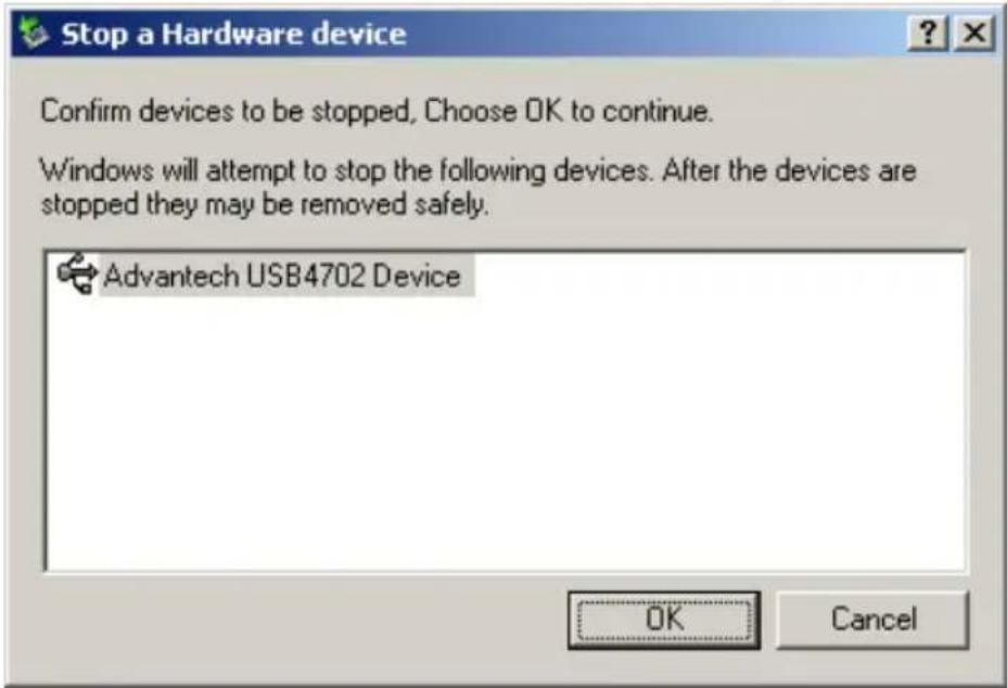
Figure 2.2: Stop a Hardware device dialog box
Step4: Unplug your USB device from the USB port.
Note: Please make sure that you have closed the application before unplugging the USB device, otherwise unexpected system error or damage may occur.
Signal Connections
This chapter provides useful information on how to connect input and output signals to the USB-4702 via the I/O connectors.
Sections include:
- Overview
- I/O Connectors
• Analog Input Connections
• Analog Output Connections - Trigger Source Connections
• Field Wiring Considerations
Chapter 3 Signal Connections
3.1 Overview
Maintaining good signal connections is one of the most important factors in ensuring that your application system is sending and receiving data correctly. A good signal connection can avoid unnecessary and costly damage to your PC and other hardware devices.
3.2 I/O Connectors
USB-4702 is equipped with one DB-37 connector that facilitates signal connections to the module.
3.2.1 Pin Assignments
Warning: The two ground references AGND and DGND should be used separately for their designated purpose. Do not connect them together.

other
| Category | Value | |---|---| | AI7 | 1 | | AI5 | 2 | | AI3 | 3 | | AI1 | 4 | | AGND | 5 | | +2.5V | 6 | | AGND | 7 | | AO1 | 8 | | AGND | 9 | | DI1 | 10 | | DI3 | 11 | | DI5 | 12 | | DI7 | 13 | | DO1 | 14 | | DO3 | 15 | | DO5 | 16 | | DO7 | 17 | | COUNT | 18 | | DGND | 19 | | Label | Value | |---|---| | AI6 | 20 | | AI4 | 21 | | AI2 | 22 | | AI0 | 23 | | AGND | 24 | | AGND | 25 | | AO0 | 26 | | AGND | 27 | | DI0 | 28 | | DI2 | 29 | | DI4 | 30 | | DI6 | 31 | | DO0 | 32 | | DO2 | 33 | | DO4 | 34 | | DO6 | 35 | | TRIG | 36 | | +5V | 37 |Figure 3.1: I/O Connector Pin Assignment
3.2.2 I/O Connector Signal Description
| Table 3.1: I/O Connector Signal Description | |||
| Signal Name R | Reference Direction Description | ||
| AI<0...7> AGND | Input Analog Input Channels 0 through 7. | ||
| AO0, AO1 AGND | Output Analog Input Channels 0 and 1. | ||
| AGND - - Analog Ground. | |||
| DI<0...7> DGND | Input Digital Input Channels 0 through 7. | ||
| DO<0...7> | DGND Output Digital Output Channels 0 through 7. | ||
| DGND | - - Digital Ground. | ||
| COUNT | DGND Input Counter Input. | ||
| TRIG | DGND Input A/D External Trigger. | ||
| +2.5V | AGND Output 2.5V DC Voltage Output. | ||
| +5V | AGND Output 5V DC Voltage Output. | ||
3.3 Analog Input Connections
USB-4702 supports 8 single-ended/4 differential analog inputs. Each individual input channel is software-selected.
3.3.1 Single-ended Channel Connections
The single-ended input configuration has only one signal wire for each channel, and the measured voltage (Vm) is the voltage of the wire as referenced against the common ground.
A signal source without a local ground is also called a “floating source”. It is fairly simple to connect a single-ended channel to a floating signal source. In this mode, USB-4702 provides a reference ground for external floating signal sources.
Figure 3.2 shows a single-ended channel connection between a floating signal source and an input channel on USB-4702.

flowchart
graph LR
    A["Measured Voltage Vm"] --> B["PGIA"]
    B --> C["Multiplexer"]
    C --> D["I/O Connector"]
    D --> E["External"]
    F["Voltage Signal Source"] --> G["+"]
    G --> H["External"]
    I["AGND"] --> J["Internal"]
    K["AI0"] --> L["External"]
    M["AI1"] --> L
    N["AI7"] --> L
    O["Vs"] --> P["External"]
Figure 3.2: Single-Ended Input Channel Connection
3.3.2 Differential Input Connections
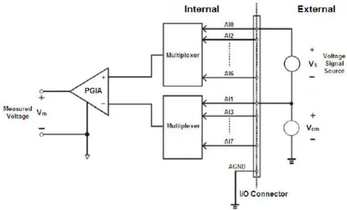
The differential input channels operate with two signal wires for each channel, and the voltage difference between both signal wires is measured. On USB-4702, when all channels are configured to differential input, up to 4 analog channels are available.
If one side of the signal source is connected to a local ground, the signal source is ground-referenced. Therefore, the ground of the signal source and the ground of the card will not be exactly of the same voltage. The difference between the ground voltages forms a commonmode voltage ( V_cm ).
To avoid the ground loop noise effect caused by common-mode voltages, you can connect the signal ground to the Low input. Figure 3.3 shows a differential channel connection between a grounded-reference signal source and an input channel on USB-4702. With this connection, the PGIA rejects a common-mode voltage V_cm between the signal source and USB-4702 ground, shown as V_cm in Figure 3.3.
Note: In differential input mode, the input channel n should be used with channel n+1 . (n=0,2,4,6)
flowchart
graph LR
    A["PGIA"] -->|Measured Voltage Vm| B["+"]
    A -->|-| C["-"]
    B --> D["Multiplexer"]
    C --> E["Multiplexer"]
    D --> F["Internal"]
    E --> G["Internal"]
    F --> H["External"]
    G --> H
    H --> I["+ Vs - Voltage Signal Source"]
    H --> J["+ Vcm - I/O Connector"]
    D --> K["A10"]
    D --> L["A12"]
    D --> M["A16"]
    E --> N["A11"]
    E --> O["A13"]
    E --> P["A17"]
    N --> Q["Ground"]
    O --> Q
    P --> Q
    Q --> R["I/O Connector"]
Figure 3.3: Differential Input Channel Connection
3.4 Analog Output Connections (Voltage)
USB-4702 provides two analog output channels, AO0 and AO1. Figure 3.4 shows how to make analog output connections on USB-4702.

flowchart
graph TD
    A["DATA BUS"] --> B["Internal"]
    B --> C["DA0"]
    B --> D["DA1"]
    C --> E["AO0"]
    D --> F["AO1"]
    E --> G["External"]
    F --> H["External"]
    G --> I["LOAD"]
    H --> J["LOAD"]
    K["AOGND"] --> L["I/O Connector"]
Figure 3.4: Analog Output Channel Connections
3.5 External Trigger Source Connections
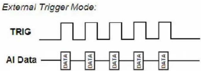
In addition to pacer triggering, USB-4702 also allows external triggering for A/D conversions. Please set the “External Trigger” in software first. And the external trigger function will be enabled with a low-to-high edge which comes from TRIG. It will trigger an A/D conversion on the USB-4702 module..
3.6 Field Wiring Considerations
- When you use USB-4702 to acquire data from outside, noises in the environment might significantly affect the accuracy of your measurements if due cautions are not taken. The following measures will be helpful to reduce possible interference running signal wires between signal sources and the USB-4702.
- The signal cables must be kept away from strong electromagnetic sources such as power lines, large electric motors, circuit breakers or welding machines, since they may cause strong electromagnetic interference. Keep the analog signal cables away from any video monitor, since it can significantly affect a data acquisition system.
- If the cable travels through an area with significant electromagnetic interference, you should adopt individually shielded, twisted-pair wires as the analog input cable. This type of cable has its signal wires twisted together and shielded with a metal mesh. The metal mesh should only be connected to one point at the signal source ground.
- Avoid running the signal cables through any conduit that might have power lines in it.
- If you have to place your signal cable parallel to a power line that has a high voltage or high current running through it, try to keep a safe distance between them. Or place the signal cable in a right angle to the power line to minimize the undesirable effect.
APPENDIX

Specifications
Appendix A Specifications
A.1 Analog Input
| Channels | 8-ch Single-ended/ 4-ch differential | ||||||||||
| Resolution | Single-ended: 11 bitsDifferential: 12 bits | ||||||||||
| FIFO Size | 512 bytes | ||||||||||
| Sampling Rate | 10 kS/s | ||||||||||
| Input Range and Gain List | Gain 1 20 16 10 | 8 5 | 4 2 1 | ||||||||
| Gain Code 4 5 2 | 9 1 | 10 0 | 4 15 | ||||||||
| S/E (V) | ±10 | - | - | - | - | - | - | - | - | ||
| Differential (V) | - | ±1 | ±1.25 | ±2 | ±2.5 | ±4 | ±5 | ±10 | ±20 | ||
| Drift | Gain G = 1 to 20 V/V | ||||||||||
| Zero (uV/°C) | 9 | ||||||||||
| Gain (ppm/°C) | 30 | ||||||||||
| Small Signal Bandwidth for PGA | Gain G = 1 to 20 V/V | ||||||||||
| Bandwidth (MHz) | 0.01 | ||||||||||
| Input Protection | 30V max. | ||||||||||
| Input Impedance | 127 k | ||||||||||
| Input Common Mode Voltage | 100mV | ||||||||||
| Accuracy | DC | Gain | G = 1 to 20 V/V | ||||||||
| INLE (LSB) | ±3 | ||||||||||
| DNLE (LSB) | ±1.5 | ||||||||||
| Gain Error (%FSR) | 0.15 | ||||||||||
A.2 Analog Output
| Channels | 2 | ||
| Resolution | 12 bits | ||
| Output range | 0~5 V | ||
| Throughput | 150 Hz Max, software-timed | ||
| Output Impedance | 51 ohm | ||
| Driving Capability | 5mA | ||
| Accuracy | DC INLE ±12LSB | ||
| DNLE ±5LSB | |||
| Dynamic Performance | Slew rate 0.7 V/us | ||
| Setting Time 10uS | |||
A.3 Non-Isolated Digital Input/Output
| Input Channels | 8 TTL | |
| Input Voltage | Low 0.8 V | max. |
| High 2.0 V | min. | |
| Output Channels | 8 (TTL) | |
| Output Voltage | Low 0.4V | max. |
| High 3.5V | min. | |
A.4 Counter
| Channels | 1 | |
| Resolution | 32 bits | |
| Input Frequency | 5 MHz max. | |
| Input Voltage | Low 0.8 V | max. |
| High 2.0 V | min. | |
A.5 General
| I/O Connector Type | 1 x DB37 female connector | |
| Dimensions | 70 x 70 mm (2.76" x 2.76") | |
| Power Consumption | Typical: +5 V @ 100 mA; Max.: +5 V @ 500 mA | |
| Temperature | Operation 0~55°C (32~131°F) (refer to IEC 68-2-1,2) | |
| Storage -20~70°C (-4~158°F) | ||
| Relative Humidity | 5~95% RH non-condensing (refer to IEC 68-2-1,2) | |
- User Manual
- Copyright
- Acknowledgements
- Product Warranty (2 years)
- CE
- Technical Support and Assistance
- Document Feedback
- Safety Precaution - Static Electricity
- Contents
- Chapter 1 Introduction ...... 2
- Chapter 2 Installation ...... 6
- Chapter 3 Signal Connections .... 12
- Appendix A Specifications .... 18
- Introduction
- Chapter 1 Introduction
- Features
- More on the CD
- Start/Programs/Advantech Automation/Advantech Device Manager / Device Driver's Manual
- Installation
- Chapter 2 Installation
- Unpacking
- After taking out the module, you should first:
- Driver Installation
- Start\Programs\Advantech Automation
- \Device Manager\Device Driver's Manual
- Hardware Uninstallation
- Signal Connections
- Chapter 3 Signal Connections
- Overview
- I/O Connectors
- Pin Assignments
- I/O Connector Signal Description
- Analog Input Connections
- Single-ended Channel Connections
- Differential Input Connections
- Analog Output Connections (Voltage)
- External Trigger Source Connections
- Field Wiring Considerations
- Specifications
- Appendix A Specifications
- A.2 Analog Output
- A.3 Non-Isolated Digital Input/Output
- A.4 Counter
- A.5 General
Brand : Advantech
Model : USB-4702-AE
Category : Module multifonction USB