
GB2 - Pump Perlick - Free user manual and instructions
Find the device manual for free GB2 Perlick in PDF.


| Product Type | Glycol Bath (Pump System) |
| Model | GB2 |
| Brand | Perlick |
| Dimensions (Exterior) | Length: 24-3/4" (629 mm), Width: 23-11/16" (602 mm), Height: 25-5/16" (643 mm) |
| Shipping Weight | 140 lbs (64 kg) |
| Electrical Requirements | 120 V, 60 Hz, 1 Phase, 12.6 A RLA, 13.6 A MCA, Max 20 A Fuse |
| Power Cord | 8 ft, 20 A, 3-wire plug (NEMA 5-20P) |
| Reservoir Capacity | 12 gallons |
| Glycol Concentration | 30% |
| Circulating Pump #1 (Heat Removal) | 140 GPH / 130 PSIG, 1/3 HP motor |
| Circulating Pumps #2, #3, #4 (Product Cooling) | 100 GPH / 130 PSIG each (up to 3 additional pumps, not all included in GB2?) |
| Number of Pumps | 1 heat removal pump + 1 recirculating pump (GB2 includes one recirculating pump; models GB3, GB4 have more) |
| Digital Temperature Controller | Factory set cut-out at 30°F, hysteresis 2°F, with display and alarms |
| Refrigeration Connection | Compatible with Perlick Refrigeration Decks (RD060, RD120) |
| Maximum Distance to Refrigeration Deck | 100 feet (contact factory for longer) |
| Clearance Requirements | Minimum 6" around unit for airflow, additional for serviceability |
| Construction | Stainless steel cabinet |
| Coolant Solution | Perlick approved #63299-1 (food grade propylene glycol with distilled water) |
| Accessories Included | Coolant connector kit, installation hardware |
| Warranty | Registration required; installation date affects warranty start |
| Compliance | California Prop 65 warning (Chromium) |
| Maintenance Intervals | Quarterly: check coolant level, concentration, clean condenser |
Frequently Asked Questions - GB2 Perlick
User questions about GB2 Perlick
0 question about this device. Answer the ones you know or ask your own.
Ask a new question about this device
Download the instructions for your Pump in PDF format for free! Find your manual GB2 - Perlick and take your electronic device back in hand. On this page are published all the documents necessary for the use of your device. GB2 by Perlick.
USER MANUAL GB2 Perlick
INSTALLATION AND OPERATION INSTRUCTIONS
ARCTICPOUR ADVANCED REFRIGERATION TECHNOLOGY
Table of Contents
Dimensional Drawings....2
Product Description 5
Installation 5
Important Safety Warnings 5
Installing the System 5
All Models 6
Connecting to a Trunk Housing 6
Connecting Trunk Housing to Dispensing Head....6
System Pak Start-Up....6
Digital Temperature Controller....7
Preventative Maintenance....9
Replacement Parts 9
Wiring Diagrams.... 11
IMPORTANT INFORMATION
To register your product, visit our web site at www.perlick.com. Click on Commercial, then Service. You will see the link to Warranty Registration Form. You must complete and submit this form or the installation date will revert back to the ship date.
Permanently mount the enclosed Warning/Safety Instruction label in a visible location near the CO2 regulator.
This manual has been prepared to assist you in the installation of your Century Remote Beer System and to acquaint you with its operation and maintenance.
We dedicate considerable time to ensure that our products provide the highest level of customer satisfaction. If service is required, your dealer can provide you with a list of qualified service agents. For your own protection, never return merchandise for credit without our approval.
We thank you for selecting a Perlick product and assure you of our continuing interest in your satisfaction.
MODELS
RD060, RD120,
RD060-O, RD120-O
GB1, GB2, GB3, GB4

Advanced Refrigeration Technology
natural_image
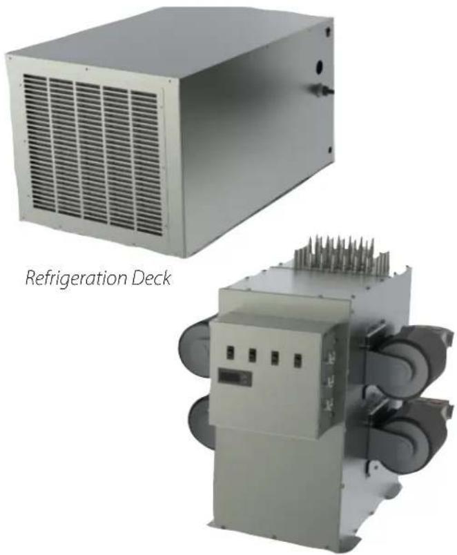
Two industrial refrigeration devices: a large rectangular chamber with ventilation grilles and a multi-chamber electrical unit with cooling fins (no visible text or symbols)Glycol Bath
Form No. Z2339
Rev. 11.30.2022

8300 West Good Hope Road · Milwaukee, WI 53223 · Phone 414.353.7060 · Fax 414.353.7069
Toll Free 800.558.5592 • E-Mail perlick@perlick.com • www.perlick.com
Air-Cooled Refrigeration Deck
| Permanently Connected Cord Connected | ||||||
| MODEL NOS. RD060 RD060-ORD120 RD120-ORD060-C | ||||||
| DIMENSIONS: EXTERIOR (mm) | Length 31-1/2" (800) 35- | 15/16" (913) 34-3/8" (873) | 8-15/16" (989) 31-1/2" (775) | |||
| Width 17-3/8" (441) 28-1 | 4" (718) 21-3/4" (552) 33-3/8" (848) 17-3/8" (445) | |||||
| Height 15-3/16" (386) 15 | 3/16" (387) 18-1/16" (459) | 18-1/16" (459) 15-3/16" (386) | ||||
| A minimum of 12" of clearance should be allowed around the entire unit for proper performance. Additional clearance should be considered for above and in front of the unit for serviceability. | ||||||
| ELECTRICAL | Voltage | 120 V | 120 V | 208/230 V | 208/230 V | 120 V |
| Frequency | 60 Hz | 60 Hz | 60 Hz | 60 Hz | 60 Hz | |
| Phase | 1∅ | 1∅ | 1∅ | 1∅ | 1∅ | |
| RLA | 11.5 | 11.5 | 19.3 | 19.3 | 11.5 | |
| MCA | 18.4 | 18.4 | 23.8 | 23.8 | ||
| Max Fuse | 30 | 30 | 40 | 40 | ||
| Cord/Plug | N/A | N/A | N/A | N/A | 14/3 NEMA 5-15P | |
| COMPRESSOR | 3/4 HP | 3/4 HP | 1.5 HP | 1.5 HP | 3/4 HP | |
| EVAPORATOR RATING @ 20°F (BTUH) | 6000 | 6000 | 12000 | 12000 | 6000 | |
| HEAT REJECTION (MAX) | 8100 | 8100 | 16800 | 16800 | 8100 | |
| REFRIGERANT | R-134a | R-134a | R-134a | R-134a | R-134a | |
| SHIPPING WEIGHT LBS (kg) | 120 (54) | 120 (54) | 140 (64) | 140 (64) | 120 (54) | |
| CABINET | Stainless Steel | |||||
| REFRIGERATION | Constant Pressure Expansion Valve, Condensing Unit with Service Valves | |||||
| REFRIGERANT CHARGE (grams) | 14.0 oz/397 g | 14.0 oz/397 g | 16 oz/453 g | 16 oz/453 g | 14.0 oz/397 g | |
Glycol Bath
| PERMANently Connected | Cord Connected | ||||||
| MODEL NOS. | GB1 | GB2 | GB3 | GB4 | GB1-C | GB2-C | |
| DIMENSIONS: EXTERIOR (mm) | Length "A" | 24-3/4"(629) | 24-3/4"(629) | 24-3/4"(629) | 24-3/4"(629) | 24-3/4"(629) | 24-3/4"(629) |
| Width "B" | 19"(483) | 23-11/16"(602) | 23-11/16"(602) | 23-11/16"(602) | 19"(483) | 23-11/16"(602) | |
| Height "C" | 25-5/16"(643) | 25-5/16"(643) | 25-5/16"(643) | 25-5/16"(643) | 25-5/16"(643) | 25-5/16"(643) | |
| A minimum of 6" of clearance should be allowed around the entire unit for proper performance. Additional clearance should be considered for above the unit and in front of the unit for servicability. | |||||||
| ELECTRICAL | Voltage | 120 V | 120 V | 120 V | 120 V | 120 V | 120 V |
| Frequency | 60 Hz | 60 Hz | 60 Hz | 60 Hz | 60 Hz | 60 Hz | |
| Phase | 1∅ | 1∅ | 1∅ | 1∅ | 1∅ | 1∅ | |
| RLA | 6.5 | 12.6 | 18.7 | 24.8 | N/A | N/A | |
| MCA | 7.6 | 13.6 | 19.6 | 25.6 | N/A | N/A | |
| Max Fuse | 15 | 20 | 25 | 30 | N/A | N/A | |
| Current/Plug | N/A | N/A | N/A | N/A | 6.5, NEMA 5-15 | 12.6, NEMA 5-20P | |
| SHIPPING WEIGHT LBS (kg) | 140 (64) | 140 (64) | 140 (64) | 140 (64) | 140 (64) | 140 (64) | |
| CIRCULATING PUMP #1 | 140 GPH / 130 PSIG | ||||||
| CIRCULATING PUMP #2, #3, #4 | 100 GPH / 130 PSIG | ||||||
| RESERVOIR CAPACITY | 12 gal | ||||||
| GLYCOL CONCENTRATION | 30% | 30% | 30% | 30% | 30% | 30% | |
| ACCESSORIES | 67451 | Coolant Connector Parts Bag, Refrigeration Deck to Glycol Bath | 61790+1 | Rack, 37" X 19-3/4", 3-Tiered | |||
| 67451-1 | Coolant Connector, Fabricated, Per Foot, Refrigeration Deck to Glycol Bath | 61790+2 | Rack, 37" X 19-3/4", 4-Tiered | ||||
| 63299-1 | Glycol Solution, 1 gallon | 57782 | Legs, Set of 4, 6"Nom | ||||
| 63335 | Coolant Connector Kit (Glycol Bath to Trunk Housing) | 68470-1 | Wall Shelf, Large (RD120) | ||||
| 63335-1 | Coolant Connector Kit (Glycol Bath to Trunk Housing) | 68470-2 | Wall Shelf, Small (RD060 or GB) | ||||
| 68455 | Flashchill Connector Kit | 68508 | Rack, ArcticPOUR, Two Tier | ||||
| C21499BSS | Stand, 35" X 22" | 68508+1 | Rack, ArcticPOUR, +1 Extension | ||||
| 61790 | Rack, 37" X 19-3/4", 2-Tiered | 68508+2 | Rack, ArcticPOUR, +2 Extension | ||||
Perlick is committed to continuous improvement. Therefore, we reserve the right to change specifications without prior notice
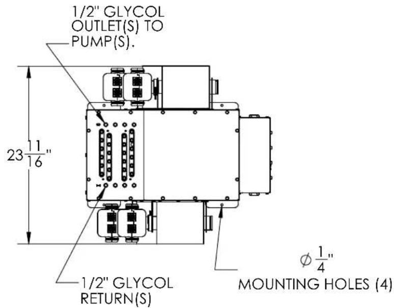
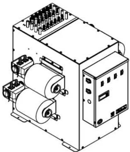
Coolant Deck Overalls
Model GB#
natural_image
Technical line drawing of an electrical control unit with coils and terminal blocks (no text or symbols)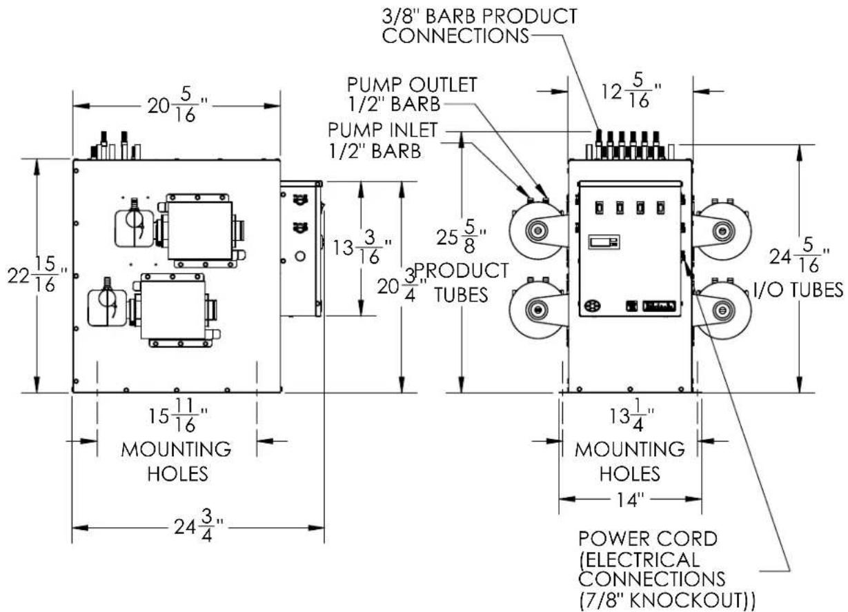
Perlick is committed to continuous improvement. Therefore, we reserve the right to change specifications without prior notice
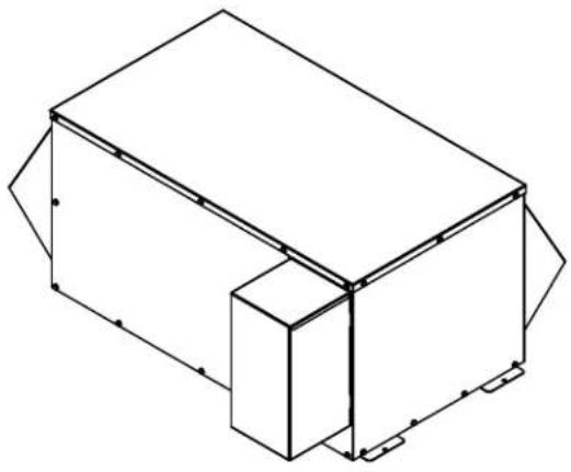
3/4 HP Refrigeration Deck Overalls
Model RD060
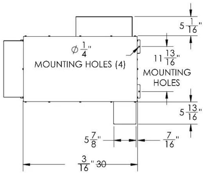
natural_image
Isometric line drawing of a 3D rectangular prism with a smaller adjacent block and corner features (no text or symbols)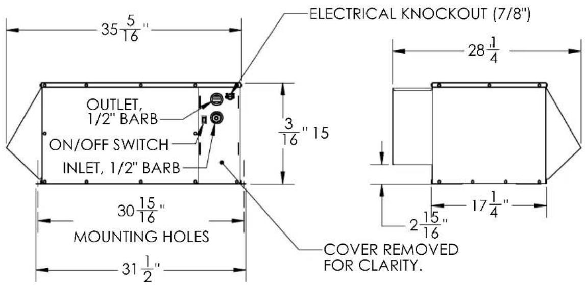
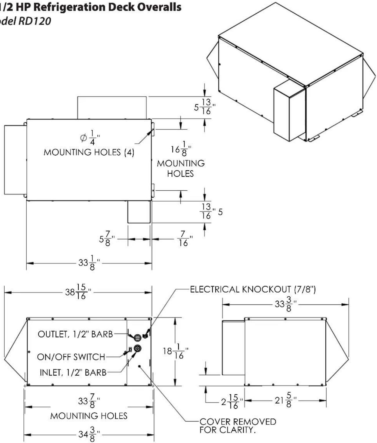
1-1/2 HP Refrigeration Deck Overalls
Model RD120
PRODUCT DESCRIPTION
Power Paks have always been an integral part of a Perlick ArcticPOUR Beer System. The ArcticPOUR Series Refrigerated Decks and Glycol Baths product line has been developed to satisfy longer beer runs, removal of heat from the indoors and flash-chilling of products.
The Refrigerated Deck is a sealed refrigeration system that can be located anywhere, including outdoors. The Glycol Bath consist of a 12 gallon resevoir with one heat removal pump and up to three additional pumps for maintaining product temperature from the walk-in cooler to the dispensing stations. In addition, up to 12 flash-chill circuits can be installed within the bath for flash-chilling for serving at lower temperatures. The heat removal pump circulates coolant solution (food grade propylene glycol with distilled water) from the bath to the refrigerated deck to maintain the bath temperature. The three additional re-circulating pumps circulate coolant solution from the bath through the insulated beverage housing from the walk-in cooler to the dispensing station(s) and back, maintaining the desired dispensing temperature at the faucet. The Glycol Bath can also include from 1 to 12 flash-chill tubes for lowering product temperatures up to 6 degrees F on a continuous pour. The Refrigerated Decks employ a direct expansion refrigeration system with a brazed plate heat exchanger for maximum efficiency and performance.
The Outdoor Refrigeration Decks includes a crankcase heater, condenser fan controls and shrouds for use in any conditions. The Glycol Baths incorporates 1/3 hp ball bearing, maintenance-free motor(s) with a 140 gph, 130 psig positive displacement pump for heat removal and 100 gph, 120 psig positive displacement pump(s) for optimum performance. In addition the Glycol Bath uses a digital temperature control for maintaining optimal bath temperature and displaying the temperature.
INSTALLATION
IMPORTANT SAFETY WARNINGS!
- Follow all National and Regional codes
- Read Operation/Installation Manual carefully before attempting to install, operate or maintain the product.
- Protect yourself and others by observing all safety
information.
- Electrical hazards exist and can cause injuries if not serviced by properly trained personnel.
- Failure to comply with instructions could result in personal injury and/or property damage!
- Retain instructions for future reference.
NOTE: Air-cooled Power Paks must be installed in areas with adequate ventilation to maintain ambient temperatures, achieve performance specifications and satisfy warranty requirements.
INSTALLING THE POWER PAK
Prior to installing a Refrigerated Deck and Glycol Deck, it is imperative that the method of connecting them to the electrical service has been determined. Ensure that the electrical service to power these systems will handle the load requirements. See the product specifications or ID plate on the equipment for Electrical Load Requirements. All units with RLA greater than 16 amps and a MCA of greater than 20 amps should be hard-wired to electrical service by a certified Electrician.
CONNECTING REFRIGERATION DECK AND GLYCOL BATH
- Determine the ideal placement of the Refrigeration Deck and Glycol Bath. It is recommended that the distance between the Refrigeration Deck and Glycol Bath does not exceed 100 feet (contact the factory if longer distances are required). NOTE: If the Refrigerated Deck is to be located on top of the walk-in cooler or in an enclosed area, it is imperative that proper ventilation is provided to prevent system failure due to overheating. Inadequate ventilation will void warranty.
- Place the Refrigeration Deck on a level surface and fasten in place using included mounting tabs if needed on Deck base. REMINDER: Allow a minimum of six inches of clearance on louvered ends of the cabinet for proper airflow. Allow accessibility room on the top of the cabinet as well as the front of the cabinet for serviceability.
- Mark Coolant Connector Lines for feed line and return line. Use compressed air to blow through the lines to identify.
- Route Coolant Connector Line Set from Refrigeration Deck to Glycol Bath.
- Remove top cover and front panel on Refrigeration Deck. Remove Access Hole Shroud (if equipped)
CONNECTING REFRIGERATION DECK AND GLYCOL BATH (cont.)
- Make coolant line connections and clamp using included Oetikers (Inlet fitting is located on the outside of the cabinet, outlet fitting is located inside the cabinet). Insulate the glycol lines completely to avoid condensation and unnecessary heat gain. (Ensure that the feed line is connected to the inlet fitting and the return line to the outlet fitting).
- Connect Low Voltage wires to the two wires with bell connectors on them [(1) Black wire, (1) White wire]. See Wiring Diagrams (pages 11-13) for proper connections.
- Connect Refrigeration Deck to proper power source. Permanently connected units should be wired per the wiring diagram and circuit should be sized according to the I.D. plate's electrical specifications. The circuit should be sized in accordance with the electrical requirements of the unit as well as in compliance with all National and Local codes (codes may require a separate disconnect for these units). NOTE: Electrical circuit should be a dedicated circuit for use only with the Refrigeration Deck.
- Make Coolant Line connections on Glycol Bath, one to pump outlet, the other to bath return tube and clamp using included Oetikers (Coolant Connector feed line).
- Remove the top front panel on the bath and the electrical box front cover.
- Connect low voltage wires to the low voltage transformer secondary wires with bell connectors (Blue and Yellow wires).
- Ensure power switches for the pump motor(s) are in the OFF position. (Check transformer to ensure the leads are connected to the low voltage side of the transformer). Make the electrical connections per the wiring diagram. The circuit should be sized in accordance with the electrical requirements of the unit as well as in compliance with all National and Local Codes (codes may require a separate disconnect for these units). NOTE: Electrical circuit should be a dedicated circuit for use only with the Glycol Bath.
• Re-install Electrical Box Cover.
CONNECTING TO FLASH CHILL COILS
If the Glycol Bath includes flash chill coils, then follow these instructions for proper connections:
- Locate Glycol Bath in-line with convenient point along the trunk housings to splice into the product lines and glycol feed line within the trunk housing (this location could be inside the
walk-in cooler, immediately outside the walk-in cooler or anyplace along the trunk housing up to the point of connection to the dispensing head).
- To make the proper connections, Flash Chill Connector kit 68455 is required. Using instructions included with kit 68455 make the necessary connections for each product tube and coolant line.
GLYCOL BATH INSIDE WALK-IN COOLER
- Connect and clamp incoming product lines to inlet of flash chill tube(s). Connect and clamp outgoing product lines to outlet of flash chill tube(s). Using included coolant loop coils from kit 68455, (pick the correct size based on the number of flash chill tubes) hook up to glycol lines (see kit instructions 68455-INS).
- Tape and insulate the coolant loop and outgoing product tubes to prevent condensation on heat gain into the newly flash chilled product lines. The product lines should be taped to the coolant lines and then combined should be fully insulated to the trunk housing insulation.
GLYCOL BATH LOCATED ALONG THE TRUNK HOUSING.
In this scenario, the pump to maintain the product temperature within the trunk housing is going to go from the pump outlet to the flash chill coolant loop, then from the flash chill coolant loop to the trunk housing coolant line to the dispensing head, then back through the trunk housing to the walk-in cooler and finally back to the Glycol Bath.
- If the trunk housing is located along the path of the trunk housing, then the trunk housing must be spliced, similarly to dropping product lines at a dispensing head, except in this case all the product lines are being dropped to the flash chill coils along with the feed line of the glycol circuit.
- Once all coolant and product connections are made using the included oetiker clamps, product lines are securely taped to the coolant lines and then all product lines and coolant lines are insulated using the included insulation to prevent condensation and heat leak.
CONNECTING TO A TRUNK HOUSING
- Inspect pump outlet port for cleanliness
-
Cut supplied coolant tubing (#54588) to required length to reach from Glycol Bath to Trunk Housing connection point.
-
Cut tubular insulation (#C12700) in half and install over previously cut coolant tubing.
- Take Oetiker clamps (#54871-210) and install over coolant tubing ends.
- Push coolant lines, one each over pump outlet barbed fitting and bath return port on bath cover.
- Position Oetikers over tube ends and clamp securely.
- Slide tubular insulation tightly against connection points. Use insulation tape as necessary to ensure an air tight seal to prevent excessive heat gain or condensation problems.
- Drill a 3-1/2" diameter hole in walk-in cooler to accommodate coolant lines.
- Slide large insulation (#57478) over remaining coolant tubing exposed to warm air conditions including inside walk-in cooler from Bath to Trunk Housing connection point. Seal and tape all seams to prevent excessive heat gain or condensation problems.
- Slide coolant lines though 3-1/2" hole previously cut in walk-in cooler wall.
- Position Trunk Housing coolant lines and Coolant Connector kit lines in horizontal position, to alleviate condensation runoff into Trunk Housing.
- Cut Trunk Housing coolant lines with tubing cutter to ensure clean burr-free ends.
- Install Oetikers over plastic coolant lines coming from bath. Slide lines over coolant lines from trunk housing and clamp Oetikers.
- Seal around hole where insulated coolant lines pass through walk-in cooler wall to ensure an air tight seal to prevent walk-in cooler problems as well as condensation.
CONNECTING TRUNK HOUSING COOLANT LINES TO DISPENSING HEAD
- Position the trunk housing so that beverage lines can be connected with a minimum cutting.
- Split trunk housing approximately 12 inches from the end to allow working room for the connections.
- Cut and deburr copper coolant lines coming from trunk housing and dispensing head. Stagger the lengths.
- Connect trunk housing coolant lines to dispensing head coolant lines using installation kit included with dispensing head connecting kit. Ensure that clamps are properly installed to guarantee a leak-free connection.
- Make product line connections from trunk housing to dispensing head.
- Pressurize lines to ensure that they are leak-free.
• After system start-up, tape product lines to coolant
lines and re-insulate product lines, gluing and taping all the seams.
SYSTEM START-UP
Use only Perlick Approved Coolant Solution (#63299-1), all other solutions and mixtures will void the Perlick warranty. The Coolant Solution has been pre-mixed for optimum performance and wear protection. The Glycol Bath resevoir holds approximately 12 gallons of solution. It takes approximately 1 gallon of Coolant Solution to fill every 60 feet of Perlick Trunk Housing.
- Never operate the circulating pumps without coolant in the resevoir.
- Fill resevoir with Perlick Coolant Solution.
- Turn Pump Switch #1 to the ON position. Coolant solution level will begin to drop in resevoir. It is filling the Coolant Connector Line set between the Glycol Bath and the Refrigeration Deck.
- Continue adding Perlick Coolant Solution until no air bubbles are apparent from the Coolant return line. NOTE: Never allow for the Coolant level in the resevoir to drop below the pump inlet tube. Allowing the level to drop below the inlet will allow air into the lines.
- Check glycol line connections at both the Bath and the Refrigeration Deck for leaks.
- Refrigeration Deck should be running if the glycol is above the set point temperature.
- Turn on power to each individual pump motor and fill all other glycol lines, adding glycol to bath as needed to maintain proper glycol level within the reservoir. Check all other glycol connections for leaks.
- Re-install Refrigeration Deck front panel and Top Cover.
- Fill reservoir to within 2 inches of the top edge of the tank. Watch return lines for additional air bubbles as this may signify additional Coolant Solution may need to be added.
- Thoroughly check all field connection points for leaks.
- Monitor Glycol Bath Temperature read-out to ensure Refrigeration Deck is working properly. Dependent on length of trunk housing run(s) and surrounding ambient conditions, these factors will determine how long it takes for the system to cut-out on the temperature control. The control is factory programmed to cut-out at 30°F with a hysteresis of 2°F. The control has also been programmed to prevent short cycling and requires one minute of off time before it will restart.
• Re-install Glycol Bath Cover.
DIGITAL TEMPERATURE CONTROLLER
The Glycol Bath comes equipped with a factory programmed electronic thermostat with display. The thermostat has numerous factory settings, which should never be adjusted or tampered with to ensure proper operation of the System. The thermostat has been factory programmed to cut-out at 30^ F with a hysteresis/differential of 2^ F.
Front Panel Commands-Normal Operation
SET: To display target set point.
DEFROST: To start a manual defrost. (This feature is available, however, the parameters for actuation are programmed, such that, no defrost is available).
UP ARROW: To see the maximum stored temperature. DOWN ARROW: To see the minimum stored temperature.
Front Panel Commands-Programming Mode
SET: Selects a parameter or confirms an operation.
UP ARROW: Browses the parameter codes or increases the displayed value.
DOWN ARROW: Browses the parameter codes or decreases the displayed value.
Meaning of LEDS
| LED | MODE | FUNCTION |
| ON | Compressor enabled | |
| Flashing | Anti-short cycle delay enabled | |
| ON | Defrost enabled | |
| ON | An alarm is occurring | |
| ON | Continuous cycle is running | |
| ON | Energy saving enabled | |
| °C/°F | ON | Measurement unit |
| °C/°F | Flashing | Programming phase |

WARNING: California Prop 65 Notice
These products may expose you to chemicals including Chromium, which are known to the state of California to cause cancer and birth defects or other reproductive harm. For more information on whether a product in this list contains these chemicals, please refer to the specific product page at perlick.com. Or to find out more about Prop 65, go to P65Warnings.ca.gov.
Perlick is committed to continuous improvement. Therefore, we reserve the right to change specifications without prior notice
Display Message Meanings
| MESSAGE MEANING | |
| Lo Minimum stored | temperature recorded since last reset |
| Hi Maximum stored | temperature recorded since last reset |
| rSt Rest is in operation (for above Stored Temperatures) | |
| POF Keyboard is locked out. No parameters can be adjusted without unlocking the keyboard. | |
Alarm Message Meanings
| ALARM MEANING ACTION | ||
| EE Data or memory failure Consult Factory | ||
| P1 Room probe failure Numerous - See note 1 | ||
| HA Maximum Temperature Alarm Numerous - See note 2 | ||
| LA | Minimum Temperature Alarm | Numerous - See note 3 |
NOTE 1: Faulty probe, loose connection, broken wire (Power Pak will continue to operate with a faulty probe. The controller has been factory programmed to continue operation with the compressor cycling on and off in 5 minute intervals.
NOTE 2: Maximum Temperature Alarm will display and flash when the factory programmed Maximum Alarm Temperature has been exceeded for 15 minutes. The Alarm will stop when temperature drops below the Maximum Alarm Temperature. Causes of this alarm may include but are not limited to: refrigeration system undersized, excessive heat leak in system, faulty refrigeration system, product temperatures to warm, line cleaning was performed.
NOTE 3: Minimum Temperature Alarm will display and flash when the factory programmed Minimum Alarm Temperature has been exceeded for 15 minutes. The Alarm will stop when temperature rises above the Minimum Alarm Temperature. Causes of this alarm may include but are not limited to: faulty control or probe, faulty refrigeration system.
How to see the Minimum Stored Temperature
- Press and release the DOWN ARROW key.
- The "Lo" message will be displayed followed by the minimum temperature recorded since the thermostat was last reset.
- By pressing the DOWN ARROW key again or by waiting 5 seconds the normal display will be restored.
How to see the Maximum Stored Temperature
- Press and release the UP ARROW key.
- The “Hi” message will be displayed followed by the maximum temperature recorded since the thermostat was last reset.
- By pressing the UP ARROW key again or by waiting 5 seconds the normal display will be restored.
How to reset the Minimum or Maximum Temperature
- Press and hold the SET key for more than 3 seconds while the minimum or maximum recorded temperature is displayed (rSt message will be displayed).
- To confirm the operation the "rSt" message starts blinking and the normal temperature will be displayed.
How to see the SET POINT
- Press and hold the SET key for more than 2 seconds to change the Set point value.
- The value of the set point will be displayed and the °F LED starts blinking.
- To change the Set value, press the UP or DOWN ARROWS, dependent on the new set point value.
- To memorize the new set point value, press the SET key again or wait 15 seconds.
WARNING: IF A MESSAGE OR INFORMATION SHOWN ON READOUT IS UNFAMILIAR, ALLOW CONTROL TO SIT FOR A MINIMUM OF 15 SECONDS AND CONTROLLER SHOULD RETURN TO DISPLAY PROBE TEMPERATURE.
PREVENTATIVE MAINTENANCE
Quarterly:
- Check Coolant Level in Reservoir. Add approved Perlick Coolant Solution (63299-1) as needed to maintain the coolant level in the reservoir.
- Check Coolant Concentration Ratio. Using an approved device, ensure that the concentration level has not declined below a 30% concentration. Approved devices include but are not limited to refractometers.
- Clean Condenser as required. This should be performed more often if unit is installed in an excessively dirty or dusty environment. Remove louvered grille to expose condenser. Remove dirt from the fin surface using a brush, vacuum or compressed gas.
Replacement Parts (RD060, RD120)
| COMPONENT RD060 RD120 | ||
| Condensing Unit, 3/4 HP, 115V 1022593 C22668 | ||
| Drier, R134A, 3/8” ID inlet, X 63297 63297 | ||
| Valve, Expansion, Constant 63826 63826 | ||
| Heat Exchanger, Brazed Plate 63300B 63300B | ||
| Coupling, 3/4” (FIPT X FIPT) 63360 63360 | ||
| Fitting, 1/2” Hose X 3/4” NPT 63361 63361 | ||
| Contactor, 2-Pole, DPST, 30A, 24 VAC Coil 1022243 1022243 | ||
| Junction Block | 57946-2 | 57946-2 |
| Wire Harness, Cond. unit | 61834-2 | 61852 |
| Wire, Jumper, 14-1 AWG, Black | 63322 63322 | |
| Wire, Jumper, 14-1 AWG, Black | 63320 63320 | |
| Wire, Jumper, 14-1 AWG, White | 63319 63319 | |
| Wire, Jumper, 14-1 AWG, White | 63318 63318 | |
| Grille, End, SS Power Pak | 64197-1SS | 64285-1SS |
| Switch, Single Pole, Rocker | 63303 63303 | |
Replacement Parts (Outdoor)
| COMPONENT RD060-O RD120-O | ||
| Fan Control | 67623 67623 | |
| Crankcase Heater | 67625 | |
| Crankcase Heater Control | 67624 67624 | |
Power Cord, 15A
| COMPONENT RD060 RD120 | ||
| Cord, 8FT-15 AMP, 3WIRE Plug-in | C22297 | |
Replacement Parts (GB)
| COMPONENT GB | |
| Insulation Cover, Glycol Pump 64425 | |
| Clamp, V-Band, Close-coupled 63291-2 | |
| Pump, Rotary Vane, Brass 67509 | |
| Fitting, 1/2” Hose Barb X 67330 | |
| Motor, Carbonator pump style 63293 | |
| Junction Block 57946 | |
| Transformer, Control, 120/208 67510 | |
| Switch, Single Pole, Rocker 63303 | |
| Sensor, NTC, S.ST., 1/4" OD X 63816-2 | |
| Fitting, Compression, Brass 63296-3 | |
| Controller, Digital, XR20CX- 67139 | |
| Wire Harness, Power Pak 63321 | |
| Wire, Jumper, 14-1 AWG, White 63318 | |
| Wire, Jumper, 14-1 AWG, White 63319 | |
| Wire, Jumper, 14-1 AWG, Black 63320 | |
| Wire, Jumper, 14-1 AWG, Black 63322 | |
| Pump, Rotary Vane, Brass 63291-1 | |
Power Cord, 15A
| COMPONENT | GB |
| Cord, 8FT-15 AMP, 3 WIRE Plug-in | C22297 |
Power Cord, 20A
| COMPONENT | GB |
| Cord, 8FT, 3 WIRE, 20 AMP | C22297A-20 |
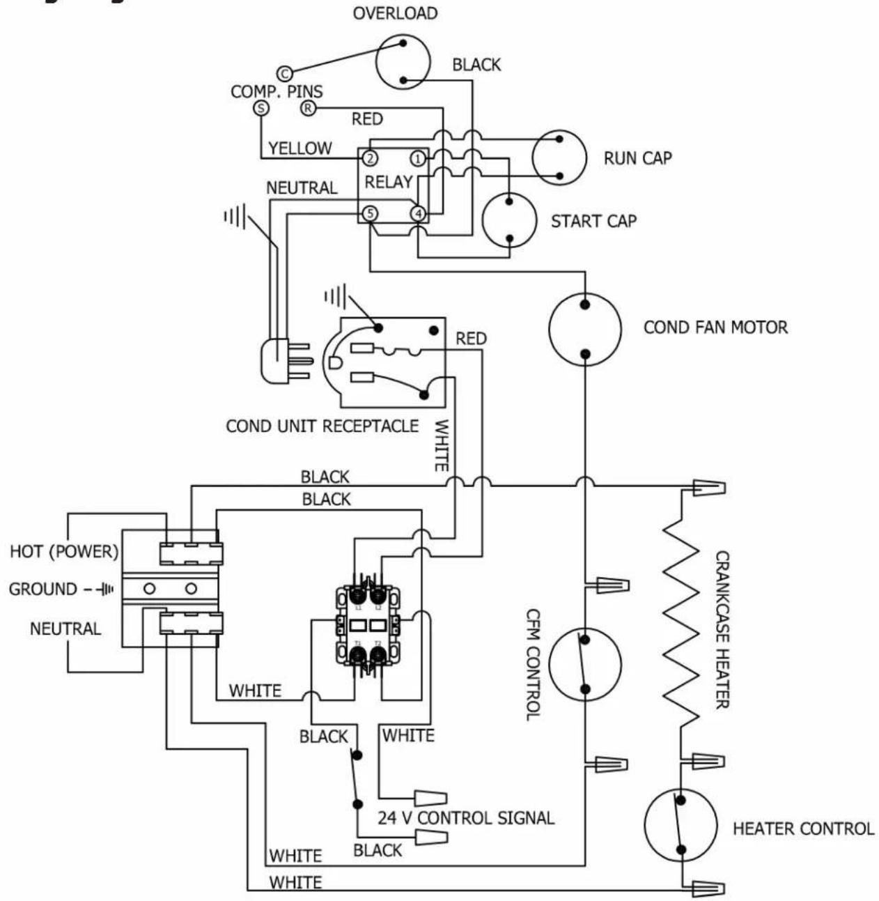
RD060 Model
Wiring Diagram
flowchart
graph TD
    A["OVERLOAD"] --> B["COMP. PINS"]
    B --> C["RED"]
    C --> D["YELLOW"]
    D --> E["RELAY"]
    E --> F["START CAP"]
    F --> G["COND FAN MOTOR"]
    G --> H["COND UNIT RECEPTACLE"]
    H --> I["WHITE"]
    I --> J["24 V CONTROL SIGNAL"]
    J --> K["WHITE"]
    K --> L["WHITE"]
    L --> M["WHITE"]
    M --> N["HEATER CONTROL"]
    N --> O["CRANKCASE HEATER"]
    O --> P["CFM CONTROL"]
    P --> Q["Black"]
    Q --> R["WHITE"]
    R --> S["WHITE"]
    S --> T["WHITE"]
    T --> U["WHITE"]
    U --> V["WHITE"]
    V --> W["WHITE"]
    W --> X["WHITE"]
    X --> Y["WHITE"]
    Y --> Z["WHITE"]
    Z --> AA["WHITE"]
    AA --> AB["WHITE"]
    AB --> AC["WHITE"]
    AC --> AD["WHITE"]
    AD --> AE["WHITE"]
    AE --> AF["WHITE"]
    AF --> AG["WHITE"]
    AG --> AH["WHITE"]
    AH --> AI["WHITE"]
    AI --> AJ["WHITE"]
    AJ --> AK["WHITE"]
    AK --> AL["WHITE"]
    AL --> AM["WHITE"]
    AM --> AN["WHITE"]
    AN --> AO["WHITE"]
    AO --> AP["WHITE"]
    AP --> AQ["WHITE"]
    AQ --> AR["WHITE"]
    AR --> AS["WHITE"]
    AS --> AT["WHITE"]
    AT --> AU["WHITE"]
    AU --> AV["WHITE"]
    AV --> AW["WHITE"]
    AW --> AX["WHITE"]
    AX --> AY["WHITE"]
    AY --> AZ["WHITE"]
    AZ --> BA["WHITE"]
    BA --> BB["WHITE"]
    BB --> BC["WHITE"]
    BC --> BD["WHITE"]
    BD --> BE["WHITE"]
    BE --> BF["WHITE"]
    BF --> BG["WHITE"]
    BG --> BH["WHITE"]
    BH --> BI["WHITE"]
    BI --> BJ["WHITE"]
    BJ --> BK["WHITE"]
    BK --> BL["WHITE"]
    BL --> BM["WHITE"]
    BM --> BN["WHITE"]
    BN --> BO["WHITE"]
    BO --> BP["WHITE"]
    BP --> BQ["WHITE"]
DANGER: ELECTRICAL SHOCK HAZARD. DISCONNECT ALL POWER BEFORE SERVICING
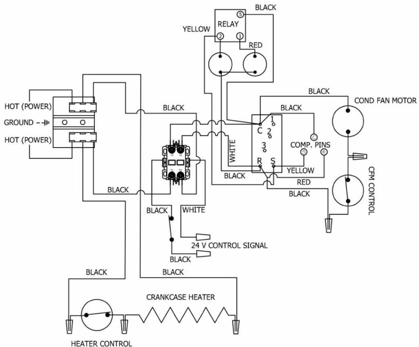
RD120 Model
Wiring Diagram
flowchart
graph TD
    A["HOT (POWER)"] --> B["Ground -"]
    B --> C["HOT (POWER)"]
    D["BLACK"] --> E["24 V CONTROL SIGNAL"]
    E --> F["Black"]
    G["WHITE"] --> H["24 V CONTROL SIGNAL"]
    H --> I["Black"]
    J["BLACK"] --> K["CRANKCASE HEATER"]
    K --> L["HEATER CONTROL"]
    M["RELAY ②"] --> N["RED"]
    O["BLACK"] --> P["RED"]
    Q["COMP. PINS"] --> R["S"]
    S["YELLOW"] --> T["R"]
    U["CFM CONTROL"] --> V["Red"]
    W["COND FAN MOTOR"] --> X["Black"]
    Y["Black"] --> Z["1"]
    AA["Black"] --> AB["3"]
    AC["Black"] --> AD["1"]
    AE["Black"] --> AF["1"]
DANGER: ELECTRICAL SHOCK HAZARD. DISCONNECT ALL POWER BEFORE SERVICING
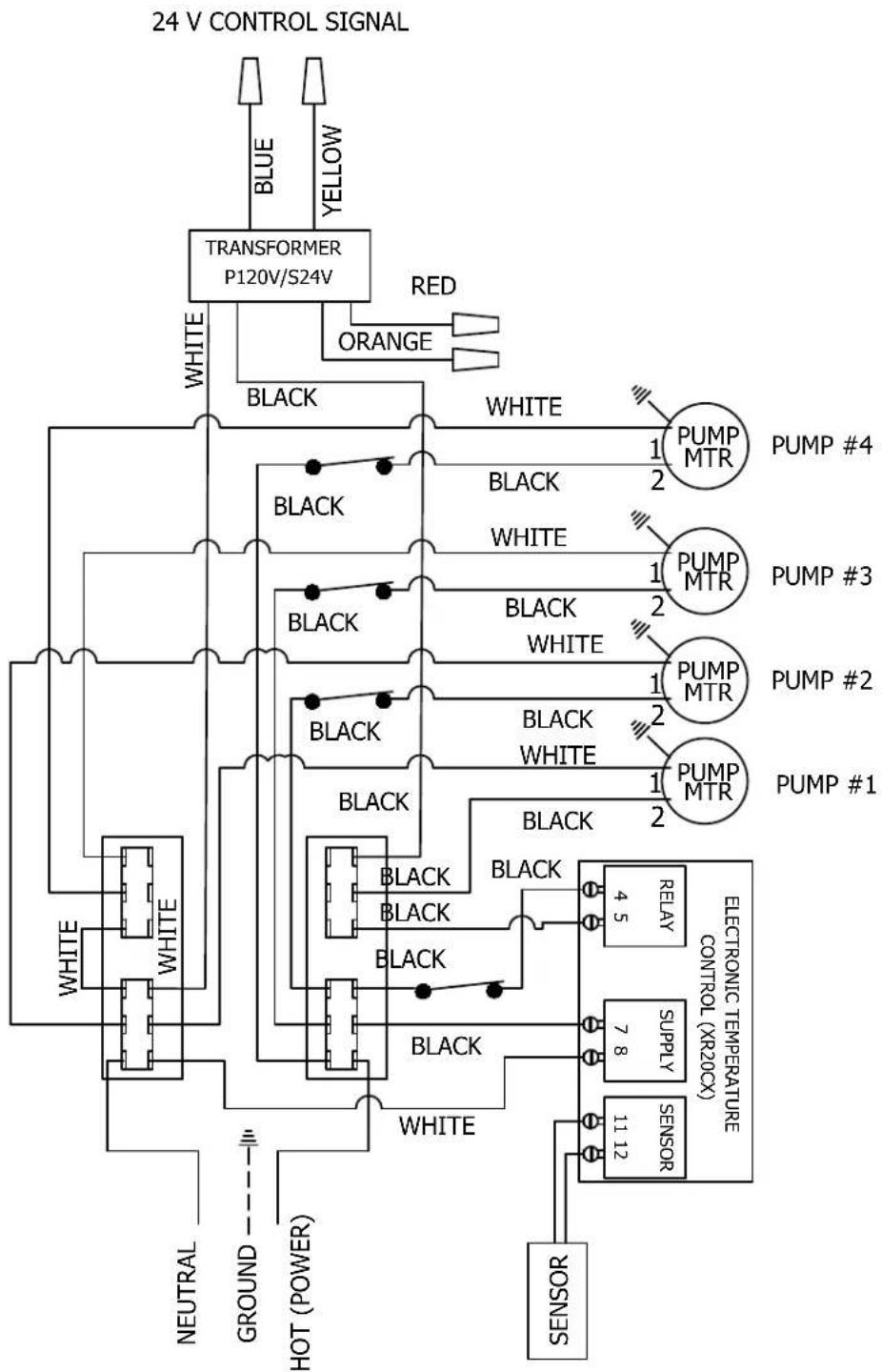
GB Model Wiring Diagram
flowchart
graph TD
    A["24 V CONTROL SIGNAL"] --> B["TRANSFORMER P120V/S24V"]
    B --> C["WHITE"]
    B --> D["RED"]
    B --> E["ORANGE"]
    B --> F["BLUE"]
    B --> G["YELLOW"]
    B --> H["BLACK"]
    H --> I["WHITE"]
    H --> J["BLACK"]
    J --> K["PUMP MTR"]
    J --> L["PUMP #4"]
    J --> M["PUMP #3"]
    J --> N["PUMP #2"]
    J --> O["PUMP #1"]
    J --> P["PUMP MTR"]
    J --> Q["PUMP #1"]
    J --> R["RELAY 4.5"]
    J --> S["SUPPLY 7.8"]
    J --> T["SENSOR 11.12"]
    J --> U["SENSOR"]
    J --> V["BLACK"]
    V --> W["BLACK"]
    V --> X["BLACK"]
    V --> Y["BLACK"]
    V --> Z["BLACK"]
    V --> AA["BLACK"]
    V --> AB["BLACK"]
    V --> AC["BLACK"]
    V --> AD["BLACK"]
    V --> AE["BLACK"]
    V --> AF["BLACK"]
    V --> AG["BLACK"]
    V --> AH["BLACK"]
    V --> AI["BLACK"]
    V --> AJ["BLACK"]
    V --> AK["BLACK"]
    V --> AL["BLACK"]
    V --> AM["BLACK"]
    V --> AN["BLACK"]
    V --> AO["BLACK"]
    V --> AP["BLACK"]
    V --> AQ["BLACK"]
    V --> AR["BLACK"]
    V --> AS["BLACK"]
    V --> AT["BLACK"]
    V --> AU["BLACK"]
    V --> AV["BLACK"]
    V --> AW["BLACK"]
    V --> AX["BLACK"]
    V --> AY["BLACK"]
    V --> AZ["BLACK"]
    V --> BA["BLACK"]
    V --> BB["BLACK"]
    V --> BC["BLACK"]
    V --> BD["BLACK"]
    V --> BE["BLACK"]
    V --> BF["BLACK"]
    V --> BG["BLACK"]
    V --> BH["BLACK"]
    V --> BI["BLACK"]
    V --> BJ["BLACK"]
    V --> BK["BLACK"]
    V --> BL["BLACK"]
    V --> BM["BLACK"]
    V --> BN["BLACK"]
    V --> BO["BLACK"]
    V --> BP["BLACK"]
    V --> BQ["BLACK"]
    V --> BR["BLACK"]
    V --> BS["BLACK"]
    V --> BT["BLACK"]
    V --> BU["BLACK"]
    V --> BV["BLACK"]
    V --> BW["BLACK"]
    V --> BX["BLACK"]
    V --> BY["BLACK"]
    V --> BZ["BLACK"]
    V --> CA["BLACK"]
    V --> CB["BLACK"]
    V --> CC["BLACK"]
    V --> CD["BLACK"]
    V --> CE["BLACK"]
    V --> CF["BLACK"]
    V --> CG["BLACK"]
    V --> CH["BLACK"]
    V --> CI["BLACK"]
    V --> CJ["BLACK"]
    V --> CK["BLACK"]
    V --> CL["BLACK"]
    V --> CM["BLACK"]
    V --> CN["BLACK"]
    V --> CO["BLACK"]
    V --> CP["BLACK"]
    V --> CQ["BLACK"]
    V --> CR["BLACK"]
    V --> CS["BLACK"]
    V --> CT["BLACK"]
    V --> CU["BLACK"]
    V --> CV["BLACK"]
    V --> CW["BLACK"]
    V --> CX["BLACK"]
    V --> CY["BLACK"]
    V --> CZ["BLACK"]
    V --> DA["BLACK"]
    V --> DB["BLACK"]
DANGER: ELECTRICAL SHOCK HAZARD. DISCONNECT ALL POWER BEFORE SERVICING
Perlick is committed to continuous improvement. Therefore, we reserve the right to change specifications without prior notice
Perlick®
Form No. Z2339
Rev. 11.30.2022
- INSTALLATION AND OPERATION INSTRUCTIONS
- Table of Contents
- IMPORTANT INFORMATION
- MODELS
- Coolant Deck Overalls
- 3/4 HP Refrigeration Deck Overalls
- Model RD060
- PRODUCT DESCRIPTION
- INSTALLATION
- IMPORTANT SAFETY WARNINGS!
- INSTALLING THE POWER PAK
- CONNECTING REFRIGERATION DECK AND GLYCOL BATH
- CONNECTING REFRIGERATION DECK AND GLYCOL BATH (cont.)
- CONNECTING TO FLASH CHILL COILS
- GLYCOL BATH INSIDE WALK-IN COOLER
- GLYCOL BATH LOCATED ALONG THE TRUNK HOUSING.
- CONNECTING TO A TRUNK HOUSING
- CONNECTING TRUNK HOUSING COOLANT LINES TO DISPENSING HEAD
- SYSTEM START-UP
- DIGITAL TEMPERATURE CONTROLLER
- Front Panel Commands-Normal Operation
- Front Panel Commands-Programming Mode
- WARNING: California Prop 65 Notice
- How to see the Minimum Stored Temperature
- How to see the Maximum Stored Temperature
- How to reset the Minimum or Maximum Temperature
- How to see the SET POINT
- PREVENTATIVE MAINTENANCE
- Quarterly:
- RD060 Model
- Wiring Diagram
- RD120 Model
- GB Model Wiring Diagram
- Perlick®
Brand : Perlick
Model : GB2
Category : Pump