GSD-1222VHP - Network switch Planet - Free user manual and instructions
Find the device manual for free GSD-1222VHP Planet in PDF.


| Product Type | 8-Port 10/100/1000T 802.3at PoE + 2-Port Gigabit SFP + 2-Port Gigabit TP Ethernet Switch |
| Model | GSD-1222VHP |
| Ports | 8 x 10/100/1000BASE-T PoE+, 2 x 1000BASE-X SFP, 2 x 10/100/1000BASE-T TP |
| PoE Standard | IEEE 802.3af/at PoE+ (PSE) |
| PoE Power Budget | 120 Watts |
| PoE Power per Port | Up to 30 Watts (802.3at) / 15.4 Watts (802.3af) |
| Switching Capacity | 24 Gbps (non-blocking) |
| Throughput | 18 Mpps @ 64 bytes |
| MAC Address Table | 8K entries |
| Jumbo Frame | Up to 9216 bytes |
| Dimensions (W x D x H) | 180 x 280 x 44 mm (1U height) |
| Weight | 1.8 kg |
| Power Supply | AC 100~240V, 50/60Hz, 2.5A max. |
| Power Consumption | Max. 130 Watts / 446 BTU |
| Enclosure | Metal case (12-inch desktop) |
| Cooling | 1 x silent fan (smart fan control) |
| Operating Temperature | -10°C to 60°C |
| Humidity | 10% to 90% (non-condensing) |
| ESD Protection | Contact ±6KV DC, Air ±8KV DC |
| Surge Protection | ±6KV |
| Certifications | FCC Class A, CE |
| LCD Display | 2-inch color LCD with smart management (PoE status, VLAN, Extend mode, etc.) |
| Mounting | Desktop (rubber feet) or rack-mount (brackets included) |
| Switch Modes | Standard, VLAN (port isolation), Extend (PoE up to 250m at 10Mbps with VLAN isolation) |
Frequently Asked Questions - GSD-1222VHP Planet
User questions about GSD-1222VHP Planet
0 question about this device. Answer the ones you know or ask your own.
Ask a new question about this device
Download the instructions for your Network switch in PDF format for free! Find your manual GSD-1222VHP - Planet and take your electronic device back in hand. On this page are published all the documents necessary for the use of your device. GSD-1222VHP by Planet.
USER MANUAL GSD-1222VHP Planet
8-/16-/24-Port 10/100/1000T 802.3at PoE+
Gigabit SFP Ethernet Switch with Smart LCD
GSD-1222VHP/GSW-1820VHP/GSW-2620VHP
User's Manual
Copyright
Copyright © 2018 by PLANET Technology Corp. All rights reserved. No part of this publication may be reproduced, transmitted, transcribed, stored in a retrieval system, or translated into any language or computer language, in any form or by any means, electronic, mechanical, magnetic, optical, chemical, manual or otherwise, without the prior written permission of PLANET.
PLANET makes no representations or warranties, either expressed or implied, with respect to the contents hereof and specifically disclaims any warranties, merchantability or fitness for any particular purpose. Any software described in this manual is sold or licensed "as is". Should the programs prove defective following their purchase, the buyer (and not PLANET, its distributor, or its dealer) assumes the entire cost of all necessary servicing, repair, and any incidental or consequential damages resulting from any defect in the software. Further, PLANET reserves the right to revise this publication and to make changes from time to time in the contents hereof without obligation to notify any person of such revision or changes
All brand and product names mentioned in this manual are trademarks and/or registered trademarks of their respective holders.
Trademarks
PLANET is a registered trademark of PLANET Technology Corp. All other trademarks belong to their respective owners.
Disclaimer
PLANET Technology does not warrant that the hardware will work properly in all environments and applications, and makes no warranty and representation, either implied or expressed, with respect to the quality, performance, merchantability, or fitness for a particular purpose.
PLANET has made every effort to ensure that this User's Manual is accurate; PLANET disclaims liability for any inaccuracies or omissions that may have occurred. Information in this User's Manual is subject to change without notice and does not represent a commitment on the part of PLANET. PLANET assumes no responsibility for any inaccuracies that may be contained in this User's Manual. PLANET makes no commitment to update or keep current the information in this User's Manual, and reserves the right to make improvements to this User's Manual and/or to the products described in this User's Manual, at any time without notice. If you find information in this manual that is incorrect, misleading, or incomplete, we would appreciate your comments and suggestions.
FCC Interference Statement
This equipment has been tested and found to comply with the limits for a Class A digital device, pursuant to Part 15 of the FCC Rules. These limits are designed to provide reasonable protection against harmful interference when the equipment is operated in a commercial environment. This equipment generates, uses, and can radiate radio frequency energy and, if not installed and used in accordance with the Instruction manual, may cause harmful interference to radio communications. Operation of this equipment in a residential area is likely to cause harmful interference in which case the user will be required to correct the interference at his own expense.
CE Mark Warning
This is a Class A product. In a domestic environment, this product may cause radio interference, in which case the user may be required to take adequate measures.
WEEE Warning
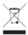
To avoid the potential effects on the environment and human health as a result of the presence of hazardous substances in electrical and electronic equipment, end users of electrical and electronic equipment should understand the meaning of the crossed-out wheeled bin symbol. Do not dispose of WEEE as unsorted municipal waste; WEEE should be collected separately.
Revision
PLANET 8-/16-/24-Port 10/100/1000T 802.3at PoE+ Gigabit SFP Ethernet Switch with Smart LCD User's Manual
Models: GSD-1222VHP, GSW-1820VHP, GSW-2620VHP
Revision: 3.0 (Dec., 2018)
Part No.: 2351-AK5070-002
Table of Contents
1. Introduction .... 5
1.1 Package Contents....5
1.2 Product Description....6
1.3 Features....10
1.4 Specifications....12
2. Hardware Description....15
2.1 Front Panel 15
2.1.1 LCD Monitor Indicators .... 16
2.1.2 LED Indicators .... 17
2.2 Rear Panel....19
2.3 LCD Management 20
2.3.1 Switch Mode 21
2.3.2 Budget Control 23
2.3.3 PSE Port Priority 24
2.3.4 PSE Port Enable....24
2.3.5 PD Type....25
2.3.6 Alive Check....26
2.3.7 Bandwidth Detection 27
2.3.8 Fan Control....28
2.3.9 Screen Saver 28
2.3.10 Language....29
2.3.11 Default Setting 29
2.3.12 System....29
3. Hardware Installation....30
3.1 Desktop Installation....31
3.2 Rack Mounting 32
3.3 Installing the SFP Transceiver....33
3.4 Product Applications....35
3.5 Power over Ethernet Powered Devices 36
4. Power over Ethernet Overview....37
5. Troubleshooting ....40
Appendix A Networking Connection ....41
A.1 Switch's Data RJ45 Pin Assignments - 1000Mbps, 1000BASE-T....41
A.2 10/100Mbps, 10/100BASE-TX ....41
1. Introduction
Thank you for purchasing PLANET 8/16/24-Port 10/100/1000T 802.3at PoE+ Gigabit SFP Ethernet Switch series, GSD-1222VHP, GSW-1820VHP and GSW-2620VHP. The descriptions of these models are shown below:
| GSD-1222VHP | 8-Port 10/100/1000T 802.3at PoE + 2-Port Gigabit SFP + 2-Port Gigabit TP Ethernet Switch |
| GSW-1820VHP | 16-Port 10/100/1000T 802.3at PoE + 2-Port Gigabit SFP Ethernet Switch |
| GSW-2620VHP | 24-Port 10/100/1000T 802.3at PoE + 2-Port Gigabit SFP Ethernet Switch |
"802.3at PoE+ Switch" is used as an alternative name in this user's manual.
1.1 Package Contents
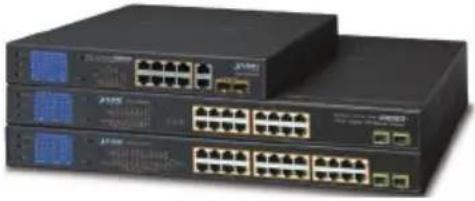
Open the box of the 802.3at PoE+ Switch and carefully unpack it. The box should contain the following items:
| 802.3at PoE+ Switch x 1 User's Manual x 1 | |
 |  |
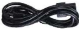
| Power Cord x 1 Screws Package x 1 | |
 |  |
| Rack-mounting Brackets x 2 Rubber Feet x 4 | |
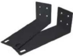 | 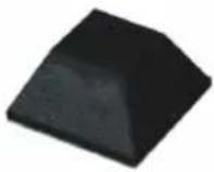 |
If any of these pieces are missing or damaged, please contact your dealer immediately; if possible, retain the carton including the original packing material, and use them again to repack the product in case there is a need to return it to us for repair.
1.2 Product Description
Ideal High-performance Integration Solution for Secure IP Surveillance Infrastructure
Particularly designed for the growing popular IP surveillance applications, PLANET GSD/GSW 802.3at PoE+ Switch series is positioned as a surveillance switch with the central power management and IP camera monitoring.
The GSD/GSW 802.3at PoE+ Switch series brings an ideal, secure surveillance system at a lower total cost. The GSD/GSW 802.3at PoE+ Switch series provides multiple 10/100/1000 Mbps 802.3at/af PoE ports able to supply sufficient PoE power to IEEE 802.3at PoE IP cameras at the same time. It is also able to be connected with an 8-/16-/32-channel NVR system, uplinked to the backbone switch and the monitoring center. With such a high-performance switch architecture, the recorded video files from the PoE IP cameras can be saved in the NVR system to enable the administrators to control and monitor the surveillance images both in the local LAN and the remote sites.
| Model GSD-1222VHP GSW-1820VHP GSW-2620VHP | |||
| 10/100/1000T Copper 8 x RJ45 16 x RJ45 24 x RJ45 | |||
| 10/100/1000T Copper 2 x RJ45 -- -- | |||
| 1000X Fiber Optic | 2 x SFP Slots | 2 x SFP Slots | 2 x SFP Slots |
| 802.3af/at PoE+ Ports | 8 | 16 | 24 |
| PoE Budget | 120 watts | 300 watts | 300 watts |
| Enclosure | 12" metal case | 19" metal case | 19" metal case |
Just "Plug and Watch" for a Quick Solution
The GSD/GSW 802.3at PoE+ Switch series is an ideal Plug and Watch Power over Ethernet solution which provides quick installation, real-time PoE work status monitoring and immediate troubleshooting through its unique LCD display to improve work efficiency and quality without any PC or software required.
The GSD/GSW 802.3at PoE+ Switch series is equipped with 8/16/24 10/100/1000BASE-T ports featuring 30-watt 802.3at Power over Ethernet Plus (PoE+) copper interfaces. With a total PoE power budget of up to 300 watts and non-blocking data switching performance, the GSD/GSW 802.3at PoE+ Switch series fulfills the demand of sufficient PoE power for HD IP surveillance. It offers a desktop-sized, reliable and visible power solution for small businesses and system integrators deploying Power over Ethernet networks.
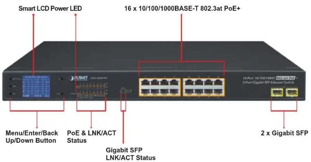
Smart and Intuitive LCD Control
The GSD/GSW 802.3at PoE+ Switch series provides an intuitive color panel on its front panel that facilitates the Ethernet management and PoE PD management. They greatly promote management efficiency in large-scale network, such as enterprises, hotels, shopping malls, government buildings, and other public areas, and feature the following special management and status functions:
■ PoE management and status
■ Port management and status
■ Switch Mode: Standard, VLAN, Extend
■ Budget and bandwidth control
■ PD alive check
■ Maintenance: Screen saver, fan control, factory default and save configuration
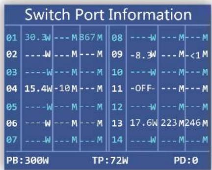
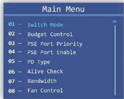
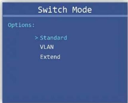

Standard, VLAN and Extend Operation Modes Offered
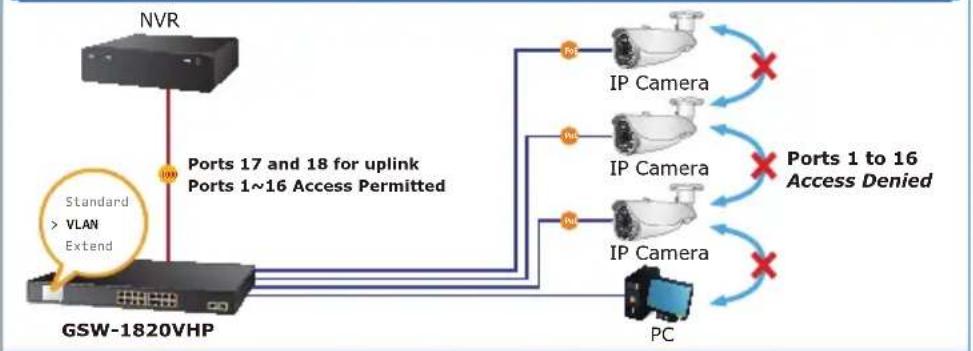
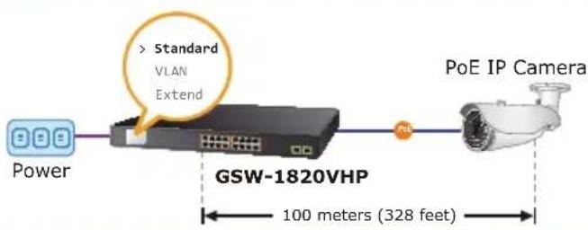
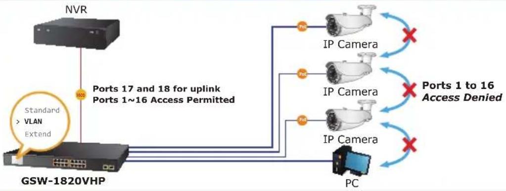
The GSD/GSW 802.3at PoE+ Switch series provides Standard, VLAN and Extend operation modes. The GSD/GSW 802.3at PoE+ Switch series operates as a normal IEEE 802.af/at PoE Switch in the Standard operation mode. The VLAN operation mode features the port-based VLAN function that can help to prevent the IP camera's multicast or broadcast storm from influencing each other.
VLAN Isolation Mode
flowchart
graph TD
    A["NVR"] -->|100 Ports 17 and 18 for uplink Ports 1~16 Access Permitted| B["IP Camera"]
    B --> C["IP Camera"]
    B --> D["IP Camera"]
    C --> E["Ports 1 to 16 Access Denied"]
    D --> F["PC"]
    G["Standard > VLAN Extend"] --> A

1000BASE-SX/LX Fiber-optic
1000BASE-T UTP
1000BASE-T UTP with PoE
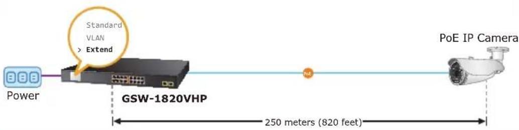
In the Extend operation mode, the GSD/GSW 802.3at PoE+ Switch series operates on a per-port basis at 10Mbps duplex operation but can support 20-watt PoE power output over a distance of up to 250 meters overcoming the 100m limit on Ethernet UTP cable. With this brand-new feature, the GSD/GSW Series provides an additional solution for 802.3af/at PoE distance extension, thus saving the cost of Ethernet cable installation. Its VLAN isolation function isolates ports so as to prevent broadcast storm and defend DHCP spoofing in the Extend operation mode.
Standard Mode (default)
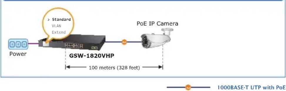
flowchart
graph LR
    A["Power"] --> B["GSW-1820VHP"]
    B --> C["PoE IP Camera"]
    D["> Standard VLAN Extend"] --> B
    B --> E["100 meters (328 feet)"]
    style A fill:#f9f,stroke:#333
    style B fill:#ccf,stroke:#333
    style C fill:#cfc,stroke:#333
    style D fill:#fcc,stroke:#333
    style E fill:#ffc,stroke:#333
Extend Mode
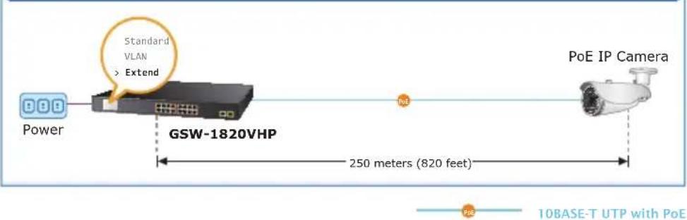
Flexible Extension Solution
The two mini-GBIC slots built in the GSD/GSW 802.3at PoE+ Switch series are compatible with the 1000BASE-SX/LX SFP (Small Form-factor Pluggable) fiber transceiver, uplinked to the backbone switch and monitoring center in long distance. The distance can be extended from 550 meters (multi-mode fiber) to 10/20/30/40/50/60/70/120 kilometers (single-mode fiber or WDM fiber). They are well suited for applications within the enterprise data centers and distributions.
Robust Protection
The GSD/GSW 802.3at PoE+ Switch series provides contact discharge of ±6KV DC and air discharge of ±8KV DC for Ethernet ESD protection. It also supports ±6KV surge immunity to improve product stability and protects users' networks from devastating ESD attacks, making sure the flow of operation does not fluctuate.
Easy Installation and Cable Connection
As data and power are transmitted over one cable, the GSD/GSW 802.3at PoE+ Switch series does not need a second cable and electrical outlets on the wall, ceiling or any unreachable place. Thus, it helps to lower the installation costs and simplify the installation effort. All the RJ45 copper interfaces of the GSD/GSW 802.3at PoE+ Switch series support 10/100/1000Mbps auto-negotiation for optimal speed detection through RJ45 Category 6, 5 or 5e cable. It also supports standard auto-MDI/MDI-X that can detect the type of connection to any Ethernet device without requiring special straight-through or crossover cables.
1.3 Features
Physical Port
GSD-1222VHP
■ 8-port 10/100/1000BASE-T Gigabit RJ45 copper
■ 2 1000BASE-X mini-GBIC SFP interfaces
■ 2 10/100/1000BASE-T TP interfaces
GSW-1820VHP
■ 16-port 10/100/1000BASE-T Gigabit RJ45 copper
■ 2 1000BASE-X mini-GBIC SFP interfaces
GSW-2620VHP
■ 24-port 10/100/1000BASE-T Gigabit RJ45 copper
■ 2 1000BASE-X mini-GBIC SFP interfaces
Power over Ethernet
■ Complies with IEEE 802.3af/at Power over Ethernet end-span PSE
■ Up to 8/16/24 ports of IEEE 802.3af/at devices powered
■ Supports PoE Power up to 32 watts for each PoE port
■ Each port supports 52V DC power to PoE powered device (GSD-1222VHP)
■ 120-watt PoE budget (GSD-1222VHP)
■ Each port supports 54V DC power to PoE powered device (GSW-1820VHP/GSW-2620VHP)
■ 300-watt PoE budget (GSW-1820VHP/GSW-2620VHP)
■ Auto detects powered device (PD)
■ Circuit protection prevents power interference between ports
■ Remote power feeding up to 100m in standard mode and 250m in extend mode
Smart LCD
■ The LCD switch features "Standard", "VLAN" and "Extend" mode selection; the "Extend" mode features 20-watt PoE transmission distance of 250m at speed of 10Mbps and VLAN isolation
■ The LCD switch is able to isolate ports to prevent broadcast storm and defend DHCP spoofing
■ Power low-voltage, power over-voltage and PSE over-temperature protection
■ Screen saver, fan control, factory default and save configuration
■ PoE management
- Total PoE power budget control
- Per port PoE function enable/disable
- PoE port power feeding priority
- Per PoE port power limitation
- PD alive check
Switching
■ Hardware-based 10/100/1000Mbps auto-negotiation and auto MDI/MDI-X
■ Flow control for full duplex operation and back pressure for half duplex operation
■ 9216bytes packet size
■ Integrates address look-up engine, supporting 8K absolute MAC addresses
■ IEEE 802.1Q VLAN transparency
■ Automatic address learning and address aging
Hardware
■ 12/19-inch desktop size, 1U height, rack mountable
■ 2-inch color LCD with smart management functions
■ LED indicators for system power, per port PoE ready and PoE activity, speed, Link/Act
■ 1/3 silent fans to provide stable and efficient power performance
■ Supports Energy-Efficient Ethernet (EEE) function (IEEE 802.3az)
■ Supports contact discharge of ±6KV DC and air discharge of ±8KV DC for Ethernet ESD protection
■ Supports ±6KV surge immunity
1.4 Specifications
| Model GSD-1 | 222VHP GSW-1820 | VHP GSW-2620VHP | |
| Hardware Specifications | |||
| 802.3af/at PoE Injector Port | 8 16 24 | ||
| 10/100/1000BASE-T MDI/MDIX Ports | 8 16 24 | ||
| 10/100/1000BASE-T MDI/MDIX Ports | 2 -- | ||
| 1000BASE-X SFP/ mini-GBIC Slots | 2 | ||
| Switch Architecture Store-and-Forward | |||
| Switch Fabric | 24Gbps/ non-blocking | 36Gbps/ non-blocking | 52Gbps/ non-blocking |
| Switch Throughput@64 bytes | 18Mpps@64 bytes 2 | 6.8Mpps@64 bytes | 38.7Mpps@64 bytes |
| MAC Address Table 8K entries | |||
| Maximum Frame Size | 9216 bytes | ||
| Flow Control | IEEE 802.3x pause frame for full duplex; back pressure for half duplex | ||
| LED Indicators | System:Power (Green)10/100/1000BASE-T RJ45 Interfaces:10/100Mbps LNK/ACT (Red)1000Mbps LNK/ACT (Green)PoE-in-Use (Amber) | ||
| 1000BASE-X SFP Interfaces:10/100Mbps LNK/ACT (Red)1000Mbps LNK/ACT (Green) | 1000BASE-X SFP Interfaces:LNK/ACT (Green) | ||
| LCD Monitor (W x D) | 40.6 x 30.5 mm, 2-inch | ||
| Buttons Menu, Enter, | Back, Up and Down | ||
| Dimensions(W x D x H) | 180 x 280 x 44mm(1U height) | 233 x 440 x 44 mm(1U height) | |
| Enclosure Metal | |||
| Weight 1.8kg 3.4kg 3.5kg | |||
| Power Requirements | AC 100~240V,50/60Hz, 2.5A max. | 100~240V AC, 50/60Hz, 5A max. | |
| Power Consumption/Dissipation | Max. 130watts/446 BTU | Max. 330watts/1132 BTU | |
| Thermal Fan 1 3 | |||
| ESD Protection | Contact discharge of ±6KV DCAir discharge of ±8KV DC | ||
| Surge Protection ±6KV | |||
| Power over Ethernet | |||
| PoE Standard | IEEE 802.3af Power over Ethernet/PSEIEEE 802.3at Power over Ethernet Plus/PSE | ||
| PoE Power Supply Type | End-span | ||
| PoE Power Output | Per port 52V-54V DC, 300mA. max. 15.4 watts (IEEE 802.3af)Per port 52V-54V DC, 600mA. max. 30 watts (IEEE 802.3at) | ||
| Power Pin Assignment | 1/2 (+), 3/6 (-) | ||
| PoE Power Budget 12 | 0 watts 300 watts | ||
| Max. Number of Class 2 PDs | 8 16 24 | ||
| Max. Number of Class 3 PDs | 8 16 23 | ||
| Max. Number of Class 4 PDs | 4 11 11 | ||
| Standards Conformance | |||
| Regulatory Compliance | FCC Part 15 Class A, CE | ||
| Standards Compliance | IEEE 802.3 10BASE-TIEEE 802.3u 100BASE-TXIEEE 802.3ab Gigabit 1000BASE-TIEEE 802.3z Gigabit SX/LXIEEE 802.3x Flow Control and Back PressureIEEE 802.3af Power over EthernetIEEE 802.3at Power over Ethernet PlusIEEE 802.3az Energy Efficient Ethernet (EEE) | ||
| Environment | |||
| Operating | Temperature: -10 ~ 60 degrees CRelative Humidity: 10 ~ 90% (non-condensing)* Temperature: < 40 degrees C; Humidity: < 90%Temperature: > 40 degrees C; Humidity: < 50% | ||
| Storage | Temperature: -10 ~ 70 degrees CRelative Humidity: 5 ~ 90% (non-condensing) | ||
2. Hardware Description
These switches provide three different running speeds – 10Mbps, 100Mbps and 1000Mbps and automatically distinguish the speed of the incoming connection. This section describes the hardware features of 802.3at PoE+ Switch. For easier management and control of the 802.3at PoE+ Switch, familiarize yourself with its display indicators and ports. Front panel illustrations in this chapter display the unit LED indicators. Before connecting any network device to the 802.3at PoE+ Switch, please read this chapter carefully.
2.1 Front Panel
The Front Panel of the 802.3at PoE+ Switch consists of 8/16/24 802.3af/at autosensing 10/100/1000Mbps Ethernet RJ45 ports and 2 Gigabit TP/SFP ports. The LCD monitor and LED Indicators are also located on the front panel of the 802.3at PoE+ Switch.

Figure 2-1: GSD-1222VHP Switch Front Panel

Figure 2-2: GSW-1820VHP Switch Front Panel

Figure 2-3: GSW-2620VHP Switch Front Panel
■ Gigabit TP Interface
10/100/1000BASE-T copper, RJ45 twisted-pair: Up to 100 meters.
Gigabit SFP Slots
1000BASE-SX/LX mini-GBIC slot, SFP (Small Factor Pluggable) transceiver module: From 550 meters (multi-mode fiber) to 10/20/30/40/50/60/70/120 kilo-meters (single-mode fiber).
Smart LCD
The Smart LCD that is located on the front panel of the GSD-1222VHP, GSW-1820VHP, GSW-2620VHP 802.3at PoE+ Switch provides "PoE Management and Status", "Switch Mode: Standard, VLAN, Extend", "Budget and Bandwidth Control", "Screen Saver", "Fan Control", and "Factory Default".
2.1.1 LCD Monitor Indicators
The 802.3at PoE+ Switch has an LCD monitor designed for network administrator who can easily obtain real-time per PoE port output watts information and system status display, such as over voltage, low voltage, and PoE chipset over temperature function. The details of each message on the LCD monitor are shown below:
GSD-1222VHP/GSW-1820VHP/GSW-2620VHP LCD Display
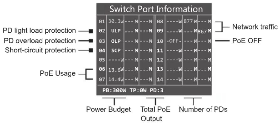
bar
Switch Port Information | Category | Power Budget (W) | Total PoE Output (M) | Number of PDs (M) | | :--- | :--- | :--- | :--- | | PD light load protection | 30.3 | 30.3 | 877 | | PD overload protection | 13.6 | 13 | 867 | | Short-circuit protection | 14.4 | 14 | 867 | | PoE Usage | 14.4 | 14 | 867 | Legend: Network traffic (■), PoE OFF (■).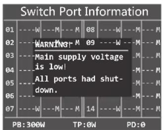
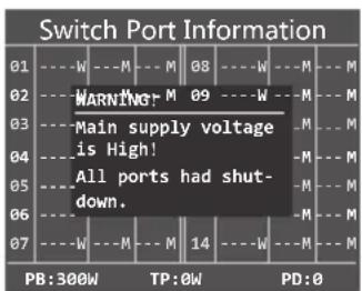
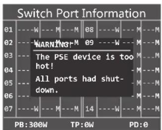
Power Low-voltage Protection Power Over-voltage Protection PSE Over-temperature Protection

Note
- The LCD screens of the GSD-1222VHP and GSW-1820VHP and GSW-2620VHP are the same, except the number of ports and port allocation.
- The LCD screens of the GSD-1222VHP and GSW-1820VHP and GSW-2620VHP will refresh every 15 seconds.
- For details on LCD Management feature, please refer to "2.3 LCD Management".
■ The detailed Smart LCD description of each item is shown below:
| Parameters Description | |
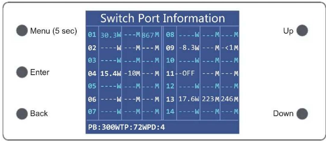
| 30.3W (example) | It means the output power port of the PoE switch. |
| OLP | It means the port is overloaded corresponding to the PSE, and the port stops powering. |
| ULP | It means the port corresponding to the PSE is lightly loaded and the port stops powering (When the current on the network is less than 7.5mA, the PSE thinks the PD has been dialed out and the port stops powering). |
| SCP | It means the port corresponding to the PSE appears to be short-circuited and the port stops powering. |
| OFF | It means the white and blue OFF shows that the port is blocked by the menu command. |
| ---W It means the port is without a PD device insert. | |
| ---M It means this port does not have data transfers. | |
| <1M It means this port data rate transfers less than 1M. | |
| 877M (example) | The white and blue character represents the data transmission rate while the red character represents the data transmission rate which is greater than the bandwidth setting, causing power to restart the PSE port. If the resumption situation happens for 10 times within 1 hour, the power supply to the port will be cut off. |
| PB It means power budget. | |
| TB It means total PoE power output information. | |
| PD The number of PDs inserted. | |
2.1.2 LED Indicators
System
| LED Color Function | |
| PWR Green Lights to indicate that the Switch has power. |
■ 10/100/1000Mbps PoE Ports
| LED Color Function | |||
| LNK/ACT Green | Lights | Indicates the link through that port is successfully established at 10/100/1000Mbps. | |
| Blinks | Indicates that the Switch is actively sending or receiving data over that port. | ||
| PoE-in-Use Amber | Lights | Indicates the port is providing DC in-line power. | |
| Off | Indicates the connected device is not a PoE powered device (PD). | ||
■ 1000Mbps SFP Slot
| LED | Color Function | ||
| LNK/ACT | Green | Lights | Indicates the port is successfully established at 1000Mbps. |
| Blinks | Indicates that the Switch is actively sending or receiving data over that port. | ||
| 1000 | Green | Lights | Indicates the port is successfully established at 1000Mbps. |
■ 1000Mbps TP Slot (GSD-1222VHP)
| LED Color Function | |||
| LNK/ACT | Green | Lights | Indicates the link through that port is successfully established at 1000Mbps. |
| Blinks | Indicates that the Switch is actively sending or receiving data over that port. | ||
| 10/100 | Red Lights | Indicates the port is successfully established at 10/100Mbps | |
| 1000 | Green Lights | Indicates the port is successfully established at 1000Mbps. | |
■ 1000Mbps TP Slot (GSW-1820VHP/GSW-2620VHP)
| LED Color Function | |||
| LNK/ACT | Green | Lights | Indicates the link through that port is successfully established at 1000Mbps. |
| Blinks | Indicates that the Switch is actively sending or receiving data over that port. | ||
| 10/100 | Red Lights | Indicates the port is successfully established at 10/100Mbps | |
| 1000 | Green Lights | Indicates the port is successfully established at 1000Mbps. | |
2.2 Rear Panel
The rear panel of the 802.3at PoE+ Switch has an AC power socket (100 to 240V AC, 50-60Hz, 2.5/5A).

Figure 2-4: GSD-1222VHP Switch Rear Panel

Figure 2-5: GSW-1820VHP/GSW-2620VHP Switch Rear Panel
■ AC Power Receptacle
For compatibility with electrical outlet standard in most areas of the world, the 802.3at PoE+ Switch's power supply automatically adjusts to line power in the range of 100-240V AC and 50/60Hz, 2.5/5A.
Plug the female end of the power cord firmly into the receptacle on the rear panel of the 802.3at PoE+ Switch and the other end into an electrical outlet, and the power will be ready.

Power
Notice
The device is a power-required device, which means it will not work till it is powered. If your networks should be active all the time, please consider using UPS (Uninterrupted Power Supply) for your device. It will prevent you from network data loss or network downtime. In some areas, installing a surge suppression device may also help to protect your 802.3at PoE+ Switch from being damaged by unregulated surge or current to the Switch or the power adapter.
2.3 LCD Management
The operation of the 5 buttons (Menu, Enter, Back, Up and Down) on the panel:
other
Switch Port Information | Position | Start (W) | End (M) | Target (M) | | :--- | :--- | :--- | :--- | | 01 | 30.3 | - | Up | | 02 | - | - | - | | 03 | - | - | - | | 04 | 15.4 | -10 | - | | 05 | - | - | - | | 06 | - | - | - | | 07 | - | - | - | | 08 | - | - | Up | | 09 | -8.3 | - | Up | | 10 | - | - | Up | | 11 | - | OFF | - | | 12 | - | - | Up | | 13 | 17.6 | W | Up | | 14 | - | W | Up | | 223 M | 246 M | - | Up | | PB: 300WTP: 72WPD: 4 Up DownPress the menu button to switch the "Switch Port Information".
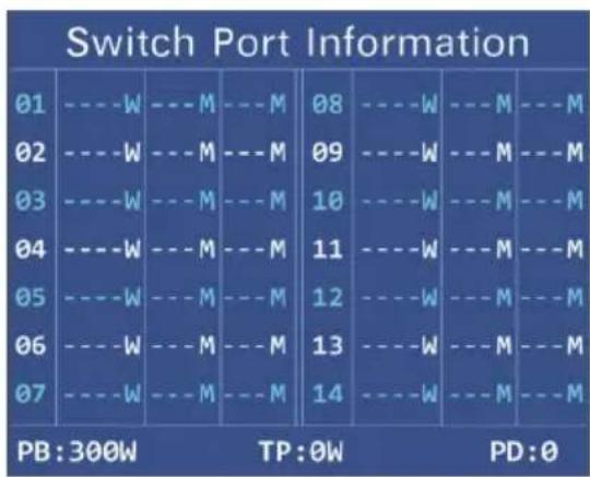
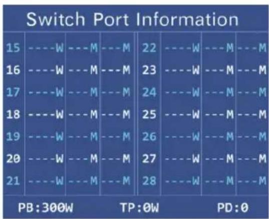
Press the menu button for about 5 seconds and enter the Main Menu. Choose a menu item by scrolling up and down, and press the "Enter" key to get to the menu item you have chosen. Press the "Back" key to return to the previous menu.
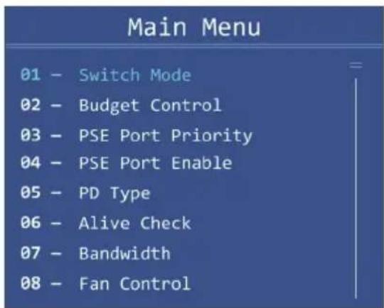
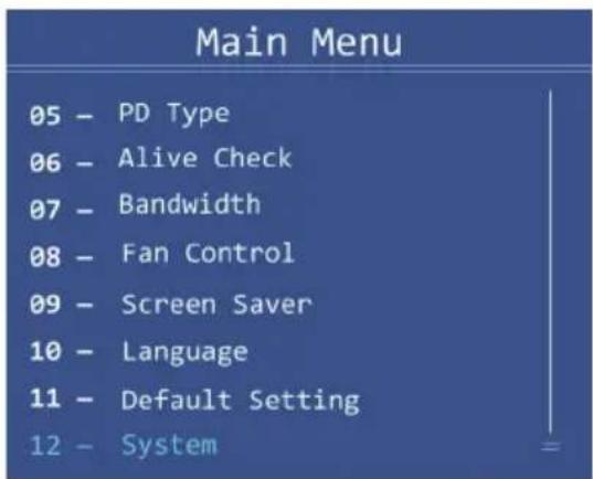
2.3.1 Switch Mode
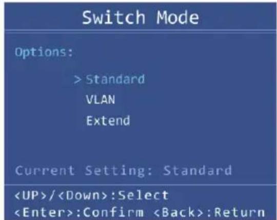
There are three modes -- "Standard", "VLAN" and "Extend" - for selection.
| Model | GSD-1222VHP GSW-18 | 20VHP GSW-2620VHP | |
| Switch Mode | Function | ||
| Standard (default) | This mode makes the 802.3at PoE+ Switch operate as a general switch and all PoE ports operate at 10/100/1000Mbps auto-negotiation. | ||
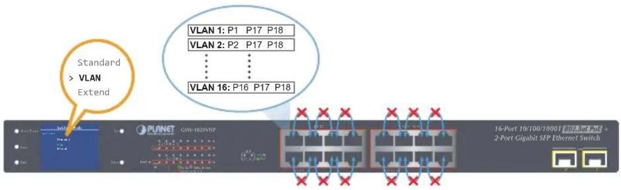
| VLAN | This mode makes the GSD-1222VHP operate as a VLAN isolation switch and1. Port 1 to port 8 will isolate respectively.2. Port 1 to port 8 can only communicate with port 9~12 (uplink port). | This mode makes the GSW-1820VHP operate as a VLAN isolation switch and1. Port 1 to port 16 will isolate respectively.2. Port 1 to port 16 can only communicate with port 17 and port 18 (uplink port). | This mode makes the GSW-2620VHP operate as a VLAN isolation switch and1. Port 1 to port 24 will isolate respectively.2. Port 1 to port 24 can only communicate with port 25 and port 26 (uplink port). |
| Extend With VLAN Isolation | ■ This mode makes the GSD-1222VHP operate as a VLAN isolation switch and1. Port 1 to port 8 will isolate respectively.2. Port 1 to port 8 can only communicate with port 9~12 (uplink port).3 20-watt PoE transmit distance of 250m at speed of 10Mbps. | ■ This mode makes the GSW-1820VHP operate as a VLAN isolation switch and1. Port 1 to port 16 will isolate respectively.2. Port 1 to port 16 can only communicate with port 17 and port 18 (uplink port).3. 20-watt PoE transmit distance of 250m at speed of 10Mbps. | ■ This mode makes the GSW-2620VHP operate as a VLAN isolation switch and1. Port 1 to port 24 will isolate respectively.2. Port 1 to port 24 can only communicate with port 25 and port 26 (uplink port).3. 20-watt PoE transmit distance of 250m at speed of 10Mbps. |
Table 2-1: GSD/GSW 802.3at PoE+ Switch Description
Standard Mode (default)

1000BASE-T UTP with PoE
VLAN Isolation Mode
flowchart
graph TD
    A["NVR"] -->|100%| B["Ports 17 and 18 for uplink Ports 1~16 Access Permitted"]
    B --> C["75E"]
    B --> D["75E"]
    B --> E["75E"]
    C --> F["IP Camera"]
    D --> G["IP Camera"]
    E --> H["IP Camera"]
    F --> I["Ports 1 to 16 Access Denied"]
    G --> I
    H --> I
    J["Standard > VLAN Extend"] --> B
    K["GSW-1820VHP"] --> L["PC"]

1000BASE-SX/LX Fiber-optic 1000BASE-T UTP 1000BASE-T UTP with PoE
Extend Mode

10BASE-T UTP with PoE
VLAN Isolation Feature
The 802.3at PoE+ Switch has one feature called VLAN function. When switching the mode to the "VLAN" position, port 1 to port 8/16/24 wouldn't able to communicate with each other.
2.3.2 Budget Control
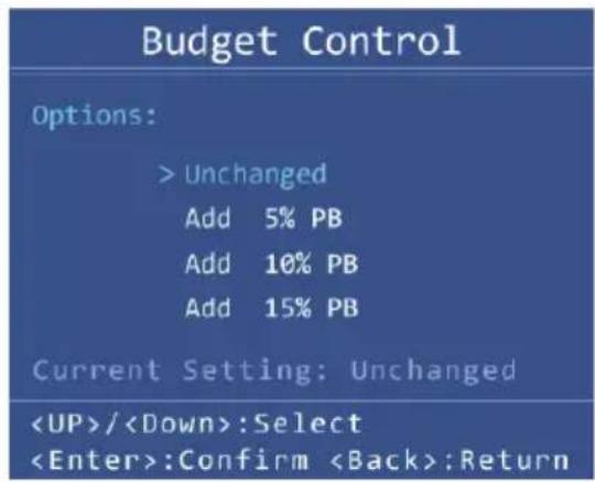
Due to the power allocation strategy of PSE, when the residual power of PoE is too large, the power distribution of the port can be increased as much as possible by increasing the power trimming of the PSE, so that the utilization of the PSE power supply can be improved. There are four levels of budget control named Unchanged (default), Add 5% PB, Add 10% PB and Add 15% PB.

-
The default PoE budget is 120W/300W in unchanged mode. If you hope to have a full load of over 120W/300W, please select Add 5% PB, Add 10% PB and Add 15% PB.
-
In order to make sure the PSE power supply is not overloaded for a long time, please try to ensure that TP is less than PB.
2.3.3 PSE Port Priority
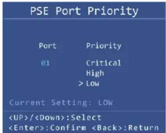
The Priority represents PoE ports priority. There are three levels of power priority named Low, High and Critical. The priority is used in case the total power consumption is over the total power budget. In this case the port with the lowest priority will be turned off, and offer power for the port of higher priority. The default port priority is "Low".
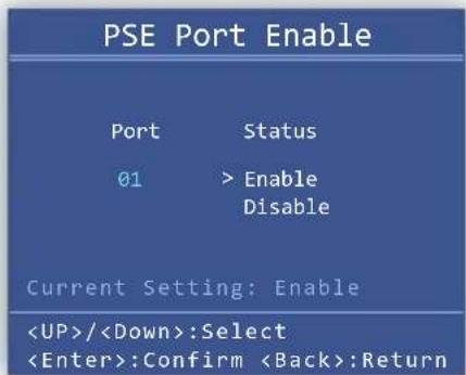
2.3.4 PSE Port Enable
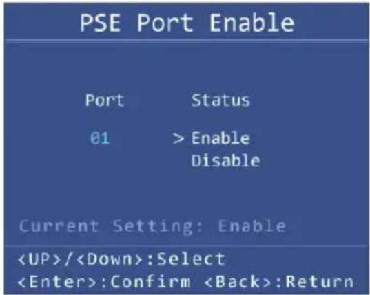
Allows user to disable or enable per port PoE function. The default is "Enable".
2.3.5 PD Type
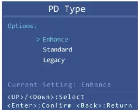
Changing the PoE power-up mode can let non-standard PDs pass the procedures of PoE power delivery process. This way, the switch can supply power to non-standard PDs. The GSD/GSW 802.3at PoE+ Switch series can set the PoE power-up mode to be in Enhance mode, Standard mode or Legacy mode by the user interface.
| Object Description | |
| Enhance (default) | On the basis of standard mode, change the PD of class 0 to AT mode; in addition, the current surge limit during power up increases to the current limit of AT. |
| Standard Fully conforms to the IEEE 802.3 af/at standard. | |
| Legacy | The legacy detection is to identify the PD devices that did not follow the IEEE 802.3af standard and their unique electrical signatures, in order for the PoE switch to provide the power to those PD devices. |
2.3.6 Alive Check
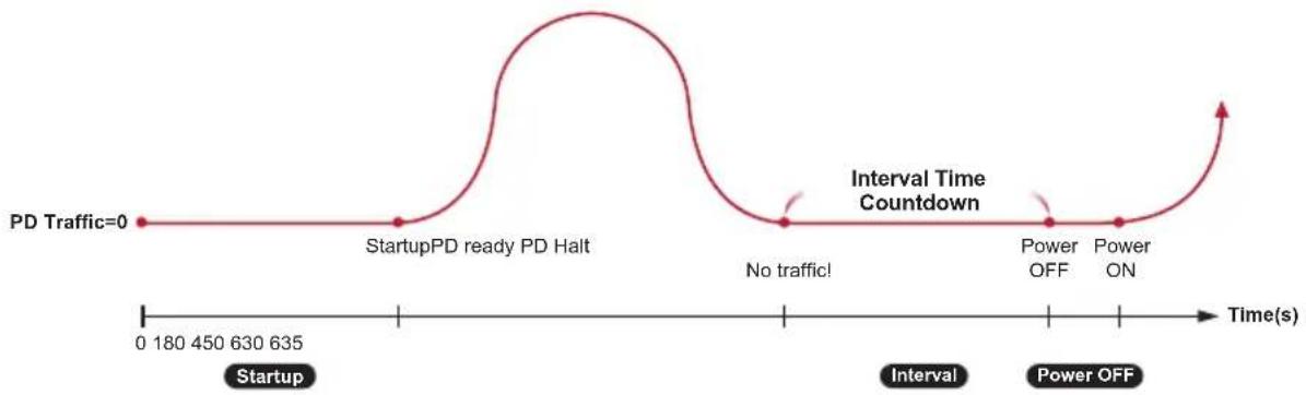
The GSD/GSW 802.3at PoE+ Switch series can be configured to monitor connected PD's status in real time via traffic detection. Once there is no traffic at interval time, the GSD/GSW 802.3at PoE+ Switch series is going to restart PoE port power, and bring the PD back to work. It will greatly enhance the reliability and reduce administrator management burden.
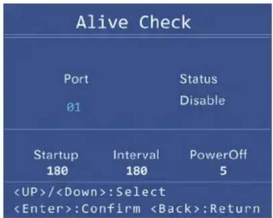
| Object Description | |
| Port Select the | port number to enable Alive Check. |
| Status | Allows user to enable or disable per port PD Alive Check function. All ports aredisabledas default value. |
| Startup Time (60~300s) | PD startup time.This startup time is based on determining when to start to measure the traffic. The default startup time is 180 seconds. |
| Interval Time (60~300s) | Traffic detection counter.The switch detects no traffic during this time and countdown for interval time begins and port begins to reboot. The default interval time is 180 seconds. |
| Power Off (5~60s) | PoE Port Disable TimerThis column allows user to set the PoE device rebooting time.The default power off time is 5 seconds. |
The PD Alive Check is not a defining standard, so the PoE device on the market doesn't report reboots done information to the PoE Switch. So user has to make sure how long it takes for the PD to finish booting, and then set the time value related column. The system is going to check the PD again according to the reboot time. If you cannot make sure the precise booting time, we suggest you set it longer.
flowchart
graph LR
    A["Start"] --> B["PD Traffic=0"]
    B --> C["StartupPD ready PD Halt"]
    C --> D["Interval Time Countdown"]
    D --> E["No traffic!"]
    E --> F["Power OFF"]
    F --> G["Power ON"]
    G --> H["Power OFF"]
    H --> I["Power ON"]
    I --> J["Power OFF"]
    J --> K["Power ON"]
    K --> L["Power OFF"]
    L --> M["Power ON"]
    M --> N["Power OFF"]
    N --> O["Power ON"]
    O --> P["Power OFF"]
    P --> Q["Power ON"]
    Q --> R["Power OFF"]
    R --> S["Power ON"]
    S --> T["Power OFF"]
    T --> U["Power ON"]
    U --> V["Power OFF"]
    V --> W["Power ON"]
    W --> X["Power OFF"]
    X --> Y["Power ON"]
    Y --> Z["Power OFF"]
    Z --> AA["Power ON"]
    AA --> AB["Power OFF"]
    AB --> AC["Power ON"]
    AC --> AD["Power OFF"]
    AD --> AE["Power ON"]
    AE --> AF["Power OFF"]
    AF --> AG["Power ON"]
    AG --> AH["Power OFF"]
    AH --> AI["Power ON"]
    AI --> AJ["Power OFF"]
    AJ --> AK["Power ON"]
    AK --> AL["Power OFF"]
    AL --> AM["Power ON"]
    AM --> AN["Power OFF"]
    AN --> AO["Power ON"]
    AO --> AP["Power OFF"]
    AP --> AQ["Power ON"]
    AQ --> AR["Power OFF"]
    AR --> AS["Power ON"]
    AS --> AT["Power OFF"]
    AT --> AU["Power ON"]
    AU --> AV["Power OFF"]
    AV --> AW["Power ON"]
    AW --> AX["Power OFF"]
    AX --> AY["Power ON"]
    AY --> AZ["Power OFF"]
    AZ --> BA["Power ON"]
    BA --> BB["Power OFF"]
    BB --> BC["Power ON"]
    BC --> BD["Power OFF"]
    BD --> BE["Power ON"]
    BE --> BF["Power OFF"]
    BF --> BG["Power ON"]
    BG --> BH["Power OFF"]
    BH --> BI["Power ON"]
    BI --> BJ["Power OFF"]
    BJ --> BK["Power ON"]
    BK --> BL["Power OFF"]
    BL --> BM["Power ON"]
    BM --> BN["Power OFF"]
    BN --> BO["Power ON"]
    BO --> BP["Power OFF"]
    BP --> BQ["Power ON"]
    BQ --> BR["Power OFF"]
    BR --> BS["Power ON"]
    BS --> BT["Power OFF"]
    BT --> BU["Power ON"]
    BU --> BV["Power OFF"]
    BV --> BW["Power ON"]
Figure 2-4: Alive Check Mechanism
2.3.7 Bandwidth Detection
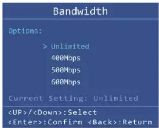
When the network transmits "the highest data rate", more than the set value, over a single port, the switch will set off an alarm to warn the overuse of the bandwidth. There are four levels of budget control, namely Unlimited (default), 400Mbps, 500Mbps and 600Mbps.
2.3.8 Fan Control
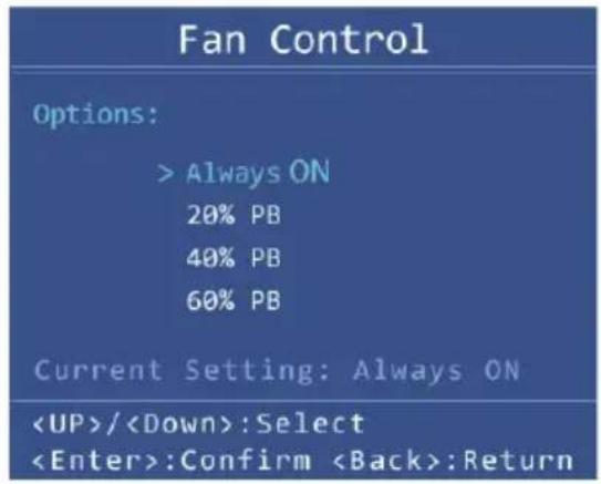
Fan control is to achieve the set power with intelligent operation. There are four levels of budget control, namely Always ON, 20% PB (default), 40% PB and 60% PB.
2.3.9 Screen Saver
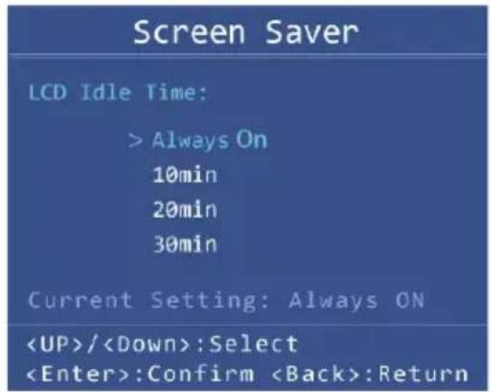
There are four levels of budget control, namely Always ON, 10min (default), 20min and 30min.
2.3.10 Language
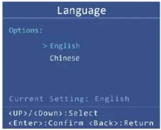
There are two languages, namely English and Chinese.
2.3.11 Default Setting
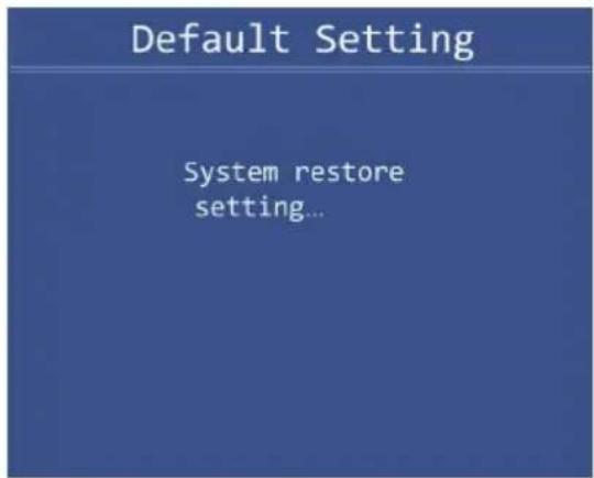
Press "Yes" to reset to default.
2.3.12 System
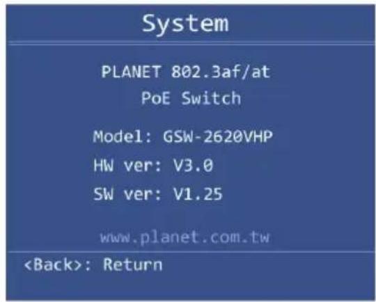
Show the system information.
3. Hardware Installation
Start up
Please refer to the following for your cabling:
10/100/1000BASE-T
All 10/100/1000BASE-T ports come with Auto-Negotiation capability. They automatically support 1000BASE-T, 100BASE-TX and 10BASE-T networks. Users only need to plug a working network device into one of the 10/100/1000BASE-T ports, and then turn on the 802.3at PoE+ Switch. The port will automatically run at 10Mbps, 20Mbps, 100Mbps or 200Mbps and 1000Mbps or 2000Mbps after the negotiation with the connected device.
Cabling
Each 10/100BASE-TX port and 10/100/1000BASE-T port uses RJ45 sockets -- similar to phone jacks -- for connection of unshielded twisted-pair cable (UTP). The IEEE 802.3/802.3u/802.3ab Fast/Gigabit Ethernet standard requires Category 5 UTP for 100Mbps 100BASE-TX. 10BASE-T networks can use Cat.3, 4, 5 or 1000BASE-T uses 5/5e/6 UTP (see table below). Maximum distance is 100 meters (328 feet).
| Port Type Cable Type Connector | |
| 10BASE-T Cat.3, 4, 5, 2-pair RJ45 | |
| 100BASE-TX Cat.5, 5e UTP, 4-pair RJ45 | |
| 1000BASE-T Cat.5/5e/6 UTP, 4-pair RJ45 |
Any Ethernet devices like hubs/PCs can connect to the 802.3at PoE+ Switch by using straight-through wires. The whole 10/100/1000Mbps ports are auto-MDI/MDI-X that can be used on straight-through or crossover cable.
3.1 Desktop Installation
To install the 802.3at PoE+ Switch on desktop, simply follow the following steps:
Step 1: Attach the rubber feet to the recessed areas on the bottom of the 802.3at PoE+ Ethernet Switch, as shown in Figure 3-1.
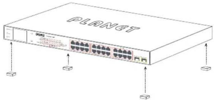
Figure 3-1: Attaching the Rubber Feet to the 802.3at PoE+ Switch
Step 2: Place the 802.3at PoE+ Switch on desktop near an AC power source.
Step 3: Keep enough ventilation space between the 802.3at PoE+ Switch and the surrounding objects.

Note
When choosing a location, please keep in mind the environmental restrictions discussed in Chapter 1, Section 4, under Specifications.
Step 4: Connect your 802.3at PoE+ Switch to 802.3af/802.3at complied power devices (PDs) and other network devices.
A. Connect one end of a standard network cable to the 10/100/1000BASE-T RJ45 ports on the front panel of the 802.3at PoE+ Switch.
B. Connect the other end of the cable to the network devices such as printer servers, workstations or routers, etc.

Note
Connection to the Switch requires UTP Category 5, 5e, 6 network cabling with RJ45 tips. For more information, please see the Cabling Specification in Appendix A.
Step 5: Supply power to the 802.3at PoE+ Switch.
A. Connect one end of the power cable to the 802.3at PoE+ Switch.
B. Connect the power plug of the power cable to a standard wall outlet.
When the 802.3at PoE+ Switch receives power, the Power LED should remain solid Green.
3.2 Rack Mounting
To install the 802.3at PoE+ Switch in a 19-inch standard rack, follow the instructions described below.
Step 1: Place your 802.3at PoE+ Switch on a hard flat surface, with the front panel positioned towards your front side.
Step 2: Attach a rack-mount bracket to each side of the 802.3at PoE+ Switch with supplied screws attached to the package. Figure 3-2 shows how to attach brackets to one side of the 802.3at PoE+ Switch.
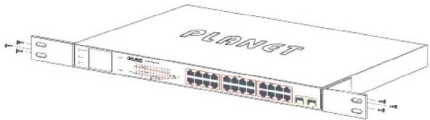
Figure 3-2: Attaching the Brackets to the 802.3at PoE+ Switch.

You must use the screws supplied with the mounting brackets. Damage caused to the parts by using incorrect screws would invalidate the warranty.
Step 3: Secure the brackets tightly.
Step 4: Follow the same steps to attach the second bracket to the opposite side.
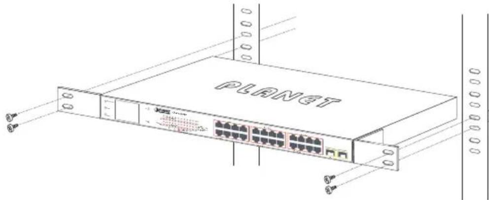
Step 5: After the brackets are attached to the 802.3at PoE+ Switch, use suitable screws to securely attach the brackets to the rack, as shown in Figure 3-3.
natural_image
Line drawing of a network switch device labeled 'PLANET' with ports and connectors (no text beyond label)Figure 3-3: Mounting the 802.3at PoE+ Switch in a Rack
Step 6: Proceed with Steps 4 and 5 of session 3.1 Desktop Installation to connect the network cabling and supply power to your Switch.
3.3 Installing the SFP Transceiver
The sections describe how to insert an SFP transceiver into an SFP slot of the 802.3at PoE+ Switch. The SFP transceivers are hot-pluggable and hot-swappable. You can plug in and out the transceiver to/from any SFP port without having to power down the 802.3at PoE+ Switch, as the Figure 3-4 shows.
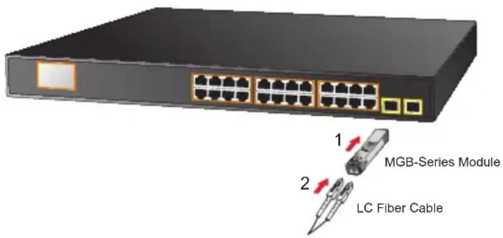
Figure 3-4: Plugging in the SFP Transceiver
■ Approved PLANET SFP Transceivers
PLANET 802.3at PoE+ Switch supports both single mode and multi-mode SFP transceivers. The following list of approved PLANET SFP transceivers is correct at the time of publication:
Gigabit SFP Transceiver Modules
■ MGB-GT SFP-Port 1000BASE-T Module
■ MGB-SX SFP-Port 1000BASE-SX mini-GBIC module - 550m
■ MGB-LX SFP-Port 1000BASE-LX mini-GBIC module - 10km
■ MGB-L30 SFP-Port 1000BASE-LX mini-GBIC module - 30km
■ MGB-L50 SFP-Port 1000BASE-LX mini-GBIC module - 50km
■ MGB-L70 SFP-Port 1000BASE-LX mini-GBIC module - 70km
■ MGB-L120 SFP-Port 1000BASE-LX mini-GBIC module - 120km
■ MGB-LA10 SFP-Port 1000BASE-LX (WDM,TX:1310nm) - 10km
■ MGB-LB10 SFP-Port 1000BASE-LX (WDM,TX:1550nm) - 10km
■ MGB-LA20 SFP-Port 1000BASE-LX (WDM,TX:1310nm) - 20km
■ MGB-LB20 SFP-Port 1000BASE-LX (WDM,TX:1550nm) - 20km
■ MGB-LA40 SFP-Port 1000BASE-LX (WDM,TX:1310nm) - 40km
■ MGB-LB40 SFP-Port 1000BASE-LX (WDM,TX:1550nm) - 40km

Note
It is recommended to use PLANET SFP on the 802.3at PoE+ Switch. If you insert an SFP transceiver that is not supported, the 802.3at PoE+ Switch will not recognize it.
-
Before we connect the 802.3at PoE+ Switch to the other network device, we have to make sure both sides of the SFP transceivers are with the same media type, for example, 1000BASE-SX to 1000BASE-SX; 1000BASE-LX to 1000BASE-LX.
-
Check whether the fiber-optic cable type matches with the SFP transceiver requirement.
To connect to 1000BASE-SX SFP transceiver, please use the multi-mode fiber cable with one side being the male duplex LC connector type.
To connect to 1000BASE-LX SFP transceiver, please use the single-mode fiber cable with one side being the male duplex LC connector type
■ Connect the Fiber Cable
- Insert the duplex LC connector into the SFP transceiver.
- Connect the other end of the cable to a device with SFP transceiver installed.
- Check the LNK/ACT LED of the SFP slot on the front of the 802.3at PoE+ Switch. Ensure that the SFP transceiver is operating correctly.
■ Remove the Transceiver Module
- Make sure there is no network activity anymore.
- Remove the Fiber-Optic Cable gently.
- Lift up the lever of the MGB module and turn it to a horizontal position.
- Pull out the module gently through the lever, as the Figure 3-5 shows.
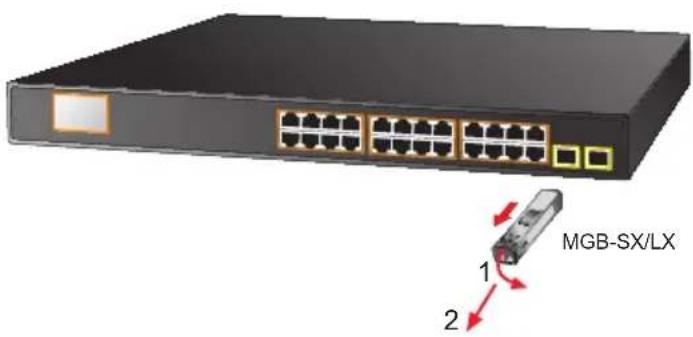
Figure 3-5: How to Pull Out the SFP Transceiver

Note
Never pull out the module without lifting up the lever of the module and turning it to a horizontal position. Directly pulling out the module could damage the module and the SFP module slot of the 802.3at PoE+ Switch.
3.4 Product Applications
Department/Workgroup PoE Switch:
Providing 8/16/24 PoE in-line power interfaces, the 802.3at PoE+ Switch can easily build a power that centrally controls IP phone system, IP camera system and wireless AP group for enterprises. Cameras can be installed around the corner in the company or campus for surveillance demands. Without the power-socket limitation, the 802.3at PoE+ Switch makes the installation of cameras easier and more efficient.
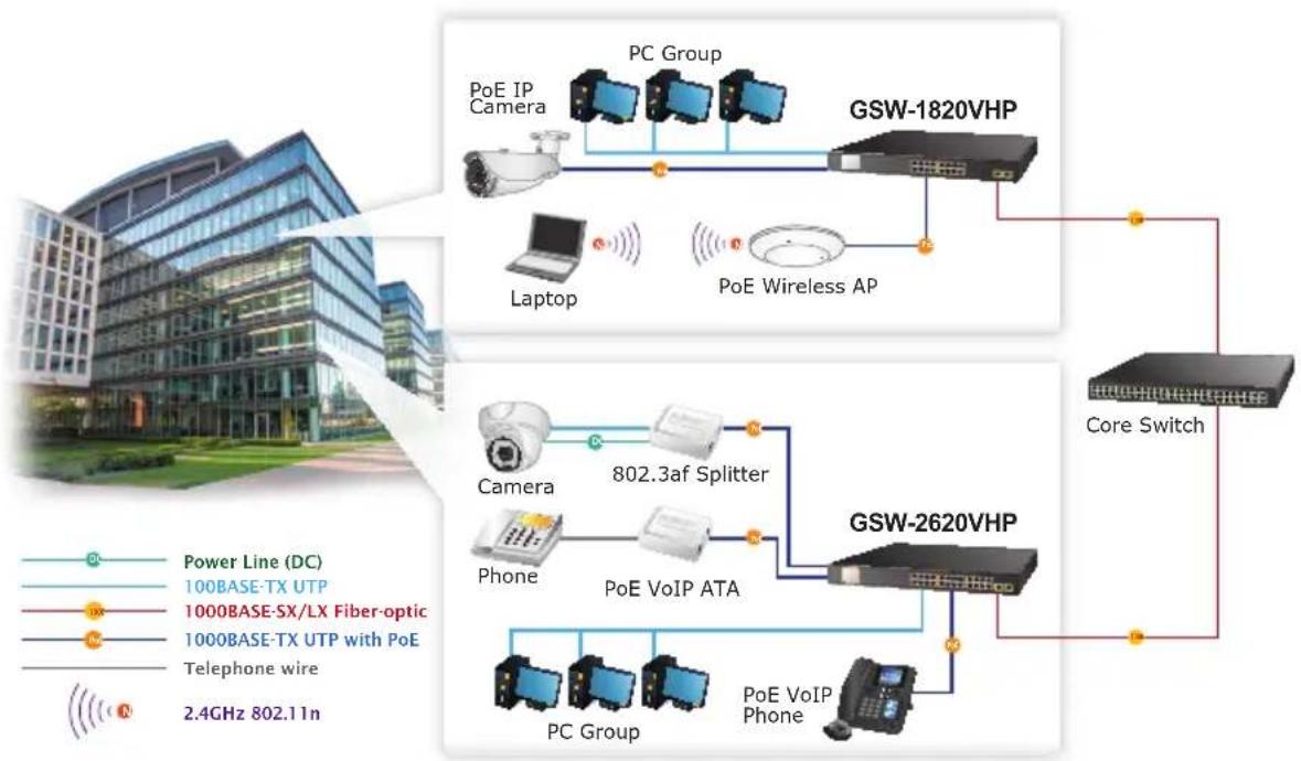
flowchart
graph TD
    subgraph_GSW-1820VHP["GSW-1820VHP"]
        A["PC Group"] --> B["Laptop"]
        B --> C["Core Switch"]
        D["PC Group"] --> E["Laptop"]
        F["PC Group"] --> G["Core Switch"]
        H["PC Group"] --> I["Core Switch"]
        J["PC Group"] --> K["Core Switch"]
    end

    subgraph_GSW-2620VHP["GSW-2620VHP"]
        L["802.3af Splitter"] --> M["Phone"]
        N["802.3af Splitter"] --> O["Phone"]
        P["802.3af Splitter"] --> Q["Phone"]
        R["802.3af Splitter"] --> S["Phone"]
        T["802.3af Splitter"] --> U["Phone"]
        V["802.3af Splitter"] --> W["Phone"]
        X["802.3af Splitter"] --> Y["Phone"]
        Z["802.3af Splitter"] --> AA["Phone"]
        AB["802.3af Splitter"] --> AC["Phone"]
        AD["802.3af Splitter"] --> AE["Phone"]
        AF["802.3af Splitter"] --> AG["Phone"]
        AH["802.3af Splitter"] --> AI["Phone"]
        AJ["802.3af Splitter"] --> AK["Phone"]
        AL["802.3af Splitter"] --> AM["Phone"]
        AN["802.3af Splitter"] --> AO["Phone"]
        AP["802.3af Splitter"] --> AQ["Phone"]
        AR["802.3af Splitter"] --> AS["Phone"]
        AT["802.3af Splitter"] --> AU["Phone"]
        AV["802.3af Splitter"] --> AW["Phone"]
        AX["802.3af Splitter"] --> AY["Phone"]
        AZ["802.3af Splitter"] --> BA["Phone"]
        BB["802.3af Splitter"] --> BC["Phone"]
        BD["802.3af Splitter"] --> BE["Phone"]
        BF["802.3af Splitter"] --> BG["Phone"]
        BH["802.3af Splitter"] --> BI["Phone"]
        BJ["802.3af Splitter"] --> BK["Phone"]
        BL["802.3af Splitter"] --> BM["Phone"]
        BN["802.3af Splitter"] --> BO["Phone"]
        BP["802.3af Splitter"] --> BQ["Phone"]
        BR["802.3af Splitter"] --> BS["Phone"]
        BT["802.3af Splitter"] --> BU["Phone"]
        BV["802.3af Splitter"] --> BW["Phone"]
        BX["802.3af Splitter"] --> BYD["Phone"]
        BZ["802.3af Splitter"] --> BQD["Phone"]
        BXZ["802.3af Splitter"] --> BQD
        BYD --> BQD
    end

    style GSW-1820VHP fill:#f9f,stroke:#333
    style GSW-2620VHP fill:#bbf,stroke:#333
Figure 3-6: Department/Workgroup 802.3at PoE+ Switch Connection
3.5 Power over Ethernet Powered Devices
 2~5 watts 2~5 watts | Voice over IP PhonesAs many as PoE VoIP phones, ATAs and other Ethernet, non-Ethernet end-devices can be installed, but UPS is needed for uninterrupted power system and power control system. |
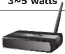 6~12 watts 6~12 watts | Wireless LAN Access PointsAccess points can readily be installed in museums, sightseeing sites, airports, hotels, campuses, factories and warehouses. |
 10~12 watts 10~12 watts | IP SurveillanceFor the sake of security, install IP cameras around enterprises, museums, campuses, hospitals and bank without considering location and electrical outlets. |
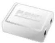 3~12 watts 3~12 watts | PoE SplitterAs PoE Splitter splits the PoE 48V DC over the Ethernet cable into 5/12V DC power output, network deployments can easily be made without worrying about power outlet locations, thus eliminating the costs for additional AC wiring and reducing the installation time. |
 3~25 watts 3~25 watts | High Power PoE SplitterAs PoE Splitter splits the PoE 53V-54V DC over the Ethernet cable into 24/12V DC power output, network deployments can easily be made without worrying about power outlet locations, thus eliminating the costs for additional AC wiring and reducing the installation time. |
 30 watts 30 watts | High Power Speed DomeThis state-of-the-art design fits very nicely in various network environments like traffic centers, shopping malls, railway stations, warehouses, airports and production facilities for the most the demanding outdoor surveillance applications. Electrician is not needed to install AC sockets. |

Since each port of the 802.3at PoE+ Switch supports 52-54V DC PoE power output, please make sure the PD's acceptable DC power range is from 52-54V DC. Otherwise, it will damage the PD.
4. Power over Ethernet Overview
What is PoE?
PoE is an abbreviation of Power over Ethernet. The PoE technology means a system safely transmits both power and data on Ethernet UTP cable. The IEEE standard for PoE technology requires Category 5 cable or higher for high power PoE levels, but can operate with Cat3 cable for low power levels. Power is supplied in common mode over two or more of the differential pairs of wires found in the Ethernet cables and comes from a power supply within a PoE-enabled network device such as an Ethernet switch or can be injected into a cable run with a mid-span power supply.
The original IEEE 802.3af-2003 PoE standard provides up to 15.4W of DC power (minimum 44V DC and 350mA) to each device. Only 12.95W is assured to be available at the powered device as some power is dissipated in the cable.
The updated IEEE 802.3at-2009 PoE standard, also known as PoE+ or PoE plus, provides up to 25.5W of power. The 2009 standard prohibits a powered device from using all four pairs for power.
The 802.3af/802.3at defines two types of source equipment: mid-span and end-span.
Mid-span
Mid-span device is placed between legacy switch and the powered device. Mid-span taps the unused wire pairs 4/5 and 7/8 to carry power; the other four are for data transmission.
End-span
End-span device is directly connected with powered device. End-span could also tap the wire 1/2 and 3/6.
PoE System Architecture
The specification of PoE typically requires two devices: the Powered Source Equipment (PSE) and the Powered Device (PD). The PSE is either an end-span or a mid-span, while the PD is a PoE-enabled terminal, such as IP phones, wireless LAN, etc. Power can be delivered over data pairs or spare pairs of standard Cat5 cabling.
▶ Powered Source Equipment (PSE)
Power sourcing equipment (PSE) is a device such as a switch that provides (sources) power on the Ethernet cable. The maximum allowed for continuous output power per cable in IEEE 802.3af is 15.4W. A later specification, IEEE 802.3at, offers 25.50W. When the device is a switch, it is commonly called an end-span (although IEEE 802.3af refers to it as endpoint). Otherwise, if it is an
intermediary device between a non-PoE capable switch and a PoE device, it is called a mid-span. An external PoE injector is a mid-span device.
Powered Device
A powered device (PD) is a device powered by a PSE and thus consumes energy. Examples include wireless access points, IP phones, and IP cameras. Many powered devices have an auxiliary power connector for an optional, external power supply. Depending on the PD design, some, none, or all power can be supplied from the auxiliary port, with the auxiliary port sometimes acting as backup power in case of PoE supplied power failure.
How Power is Transferred through Cable
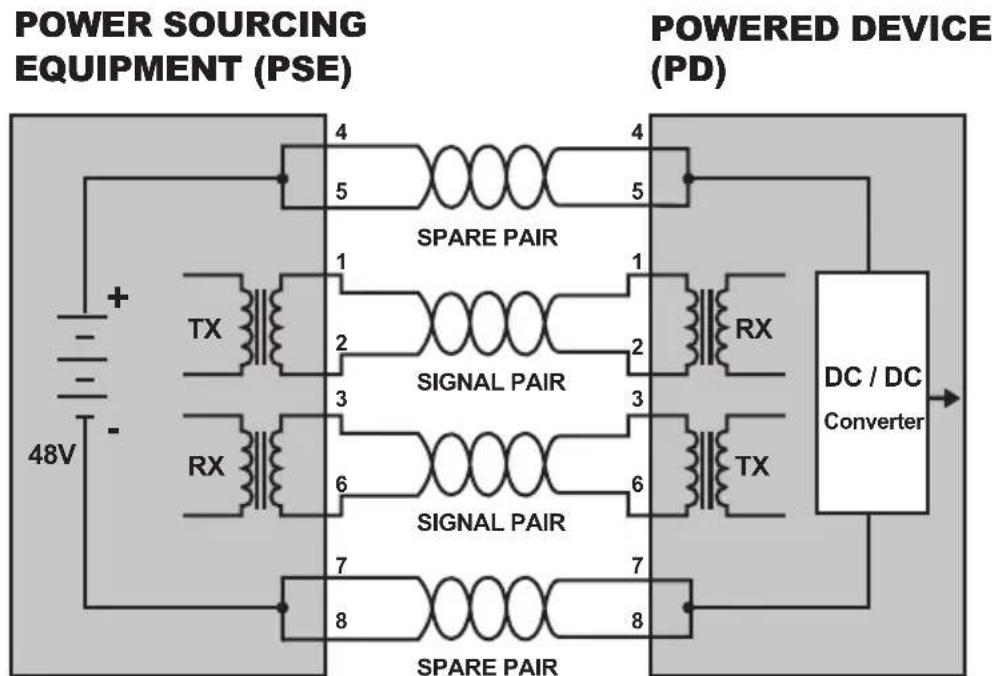
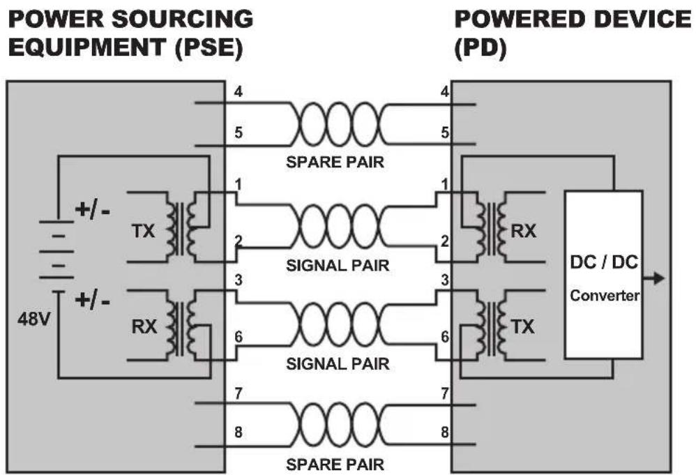
A standard Cat5 Ethernet cable has four twisted pairs, but only two of these are used for 10BASE-T and 100BASE-TX. The specification allows two options for using these cables for power, shown in Figure 1 and Figure 2:
The spare pairs are used. Figure 1 shows the pair on pins 4 and 5 connected together and forming the positive supply, and the pair on pins 7 and 8 connected and forming the negative supply. (In fact, a late change to the spec allows either polarity to be used).
flowchart
graph TD
    A["48V Power Supply"] --> B["SPARE PAIR"]
    B --> C["RS1 TX"]
    B --> D["RS2 RX"]
    B --> E["RS3 TX"]
    B --> F["RS4 RX"]
    G["POWER SOURCEING EQUIPMENT (PSE)"] --> H["4"]
    G --> I["5"]
    G --> J["6"]
    G --> K["7"]
    G --> L["8"]
    M["POWERED DEVICE (PD)"] --> N["4"]
    M --> O["5"]
    M --> P["6"]
    M --> Q["7"]
    M --> R["8"]
    S["DC / DC Converter"] --> T["Output"]
Figure 1: Power Supplied over Spare Pins
The data pairs are used. Since Ethernet pairs are transformers coupled at each end, it is possible to apply DC power to the center tap of the isolated transformer without upsetting the data transfer. In this mode of operation, the pair on pins 3 and 6 and the pair on pins 1 and 2 can be of either polarity.
flowchart
graph TD
    A["48V"] --> B["+/-"]
    B --> C["TX"]
    C --> D["SPARE PAIR"]
    D --> E["1"]
    E --> F["SIGNAL PAIR"]
    F --> G["2"]
    G --> H["RX"]
    H --> I["DC / DC Converter"]
    I --> J["7"]
    J --> K["TX"]
    K --> L["SPARE PAIR"]
    L --> M["8"]
    M --> N["SIGNAL PAIR"]
    N --> O["6"]
    O --> P["RX"]
    P --> Q["DC / DC Converter"]
    Q --> R["7"]
    R --> S["TX"]
    S --> T["SPARE PAIR"]
    T --> U["8"]
    U --> V["SIGNAL PAIR"]
    V --> W["6"]
    W --> X["RX"]
    X --> Y["DC / DC Converter"]
Figure 2: Power Supplied over Data Pins
When to install PoE
Consider the following scenarios:
- You're planning to install the latest VoIP phone system to minimize cabling building costs when your company moves into a new office next month.
- The company staff has been clamoring for a wireless access point in the picnic area behind the building so they can work on their laptops through lunch, but the cost of electrical power to the outside is not affordable.
- Management asks for IP Surveillance Cameras and business access systems throughout the facility, but they would rather avoid another electrician's payment.
5. Troubleshooting
This chapter contains information to help you solve issues. If the 802.3at PoE+ Switch is not functioning properly, make sure the 802.3at PoE+ Switch was set up according to instructions in this manual.
The Link LED is not lit.
Solution:
Check the cable connection and also try to swap one new cable.
1000BASE-T port link LED is lit, but the traffic is irregular.
Solution:
Make sure the attached device is not set to full duplex. Some devices use a physical or software switch to change duplex modes. Auto-negotiation may not recognize this type of full-duplex setting.
Why the Switch doesn't connect to the network.
Solution:
Check the LNK/ACT LED on the 802.3at PoE+ Switch. Try another port on the 802.3at PoE+ Switch. Make sure the cable is installed properly. Make sure the cable is the right type. Turn off the power. After a while, turn on the power again.
Why the GSD/GSW Switch, connected to PoE device, cannot be powered on.
Solution:
- Please check the cable type of the connection from GSD/GSW switch to the other end. The cable should be an 8-wire UTP, Category 5 or above and EIA568 cable within 100 meters. A cable with only 4-wire, short loop or over 100 meters will affect the power supply.
- Please make sure the device is fully complied with IEEE 802.3af/IEEE 802.3at standard.
What is the power output of each PoE port?
Solution:
- Each PoE port supports 52-54V DC, 600mA and a maximum of 30 watts of power output. Detect and inject by the standard of IEEE 802.3at.
- Each PoE port supports 52-54V DC, 300mA and a maximum of 15.4 watts of power output. Detect and inject by the standard of IEEE 802.3af.
Appendix A Networking Connection
A.1 Switch's Data RJ45 Pin Assignments - 1000Mbps, 1000BASE-T
| PIN NO MDI MDI-X | |
| 1 BI_DA+ BI_DB+ | |
| 2 BI_DA- BI_DB- | |
| 3 BI_DB+ BI_DA+ | |
| 4 BI_DC+ BI_DD+ | |
| 5 BI_DC- BI_DD- | |
| 6 BI_DB- BI_DA- | |
| 7 BI_DD+ BI_DC+ | |
| 8 BI_DD- BI_DC- |
Implicit implementation of the crossover function within a twisted-pair cable, or at a wiring panel, while not expressly forbidden, is beyond the scope of this standard.
A.2 10/100Mbps, 10/100BASE-TX
When connecting Switch to another Fast Ethernet switch, a straight-through or crossover cable might be necessary. Each port of the Switch supports auto-MDI/MDI-X detection, meaning you can directly connect the Switch to any Ethernet devices without making a crossover cable. The following table and diagram show the standard RJ45 receptacle/connector and their pin assignments:
| RJ45 Connector Pin Assignment | ||
| Contact | MDIMedia Dependent Interface | MDI-XMedia Dependent Interface - Cross |
| 1 | Tx + (transmit) | Rx + (receive) |
| 2 | Tx - (transmit) | Rx - (receive) |
| 3 | Rx + (receive) | Tx + (transmit) |
| 4, 5 | Not used | |
| 6 | Rx - (receive) | Tx - (transmit) |
| 7, 8 | Not used | |
The standard cable, RJ45 pin assignment
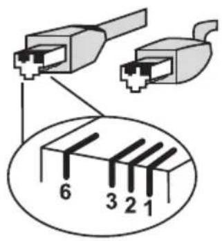
The standard RJ45 receptacle/connector
There are 8 wires on a standard UTP/STP cable and each wire is color-coded. The following shows the pin allocation and color of straight-through cable and crossover cable connection:
| Straight Cable | SIDE 1 | SIDE 2 | |||||||||||
| 1 | 2 | 3 | 4 | 5 | 6 | 7 | 8 | SIDE 1 | 1 = White/Orange | 2 = Orange | 1 = White/Orange | 2 = Orange | |
| 1 | 2 | 3 | 4 | 5 | 6 | 7 | 8 | 4 = Blue | 5 = White/Blue | 4 = Blue | 5 = White/Blue | ||
| SIDE 2 | 6 = Green | 7 = White/Brown | 8 = Brown | 6 = Green | |||||||||
| 7 = White/Brown | |||||||||||||
| 8 = Brown | |||||||||||||
| Crossover Cable | SIDE 1 SIDE 2 | ||
| 1 | 2 | 3 | 4 |
Figure A-1: Straight-through and Crossover Cable
Please make sure your connected cables are with the same pin assignment and color as the above picture before deploying the cables into your network.
EC Declaration of Conformity
For the following equipment:
*Type of Product : 8-Port 10/100/1000T 802.3at PoE + 2-Port 10/100/1000T + 2-Port 1000X SFP Ethernet Switch with PoE LCD Monitor
*Model Number : GSD-1222VHP
* Produced by:
Manufacturer's Name : Planet Technology Corp.
Manufacturer's Address : 10F., No.96, Minquan Rd., Xindian Dist., New Taipei City 231, Taiwan
is herewith confirmed to comply with the requirements set out in the Council Directive on the Approximation of the Laws of the Member States relating to Electromagnetic Compatibility Directive 2014/30/EU.
For the evaluation regarding the EMC, the following standards were applied:
EN 55032 2015+AC:2016 Class A
AS/NZS CISPR 32 2015 Class A
EN 61000-3-2 2014 Class A
EN 61000-3-3 2013
EN 55035 2017
EN 60950-1
2006+A11:2009+A1:2010+A12:2011+A2:2013
Responsible for marking this declaration if the:
Manufacturer
☐ Authorized representative established within the EU
Authorized representative established within the EU (if applicable):
Company Name:
Planet Technology Corp.
Company Address:
10F., No.96, Minquan Rd., Xindian Dist., New Taipei City 231, Taiwan
Person responsible for making this declaration
Name, Surname
Jonas Yang
Position / Title :
Product Manager
Taiwan
Place
EC Declaration of Conformity
For the following equipment:
*Type of Product : 16/24-Port 10/100/1000T 802.3at PoE + 2-Port Gigabit SFP Ethernet Switch with LCD PoE Monitor (300W)
*Model Number : GSW-1820VHP, GSW-2620VHP
* Produced by:
Manufacturer's Name : Planet Technology Corp.
Manufacturer's Address : 10F., No.96, Minquan Rd., Xindian Dist., New Taipei City 231, Taiwan
is herewith confirmed to comply with the requirements set out in the Council Directive on the Approximation of the Laws of the Member States relating to Electromagnetic Compatibility Directive 2014/30/EU.
For the evaluation regarding the EMC, the following standards were applied:
EN 55032 2015 Class A
AS/NZS CISPR 32 2015
EN 61000-3-2 2014 Class A
EN 61000-3-3 2013
EN 55024 2010+A1:2015
Responsible for marking this declaration if the:
☑ Manufacturer ☐ Authorized representative established within the EU
Authorized representative established within the EU (if applicable):
Company Name: Planet Technology Corp.
Company Address: 10F., No.96, Minquan Rd., Xindian Dist., New Taipei City 231, Taiwan
Person responsible for making this declaration
Name, Surname Jonas Yang
Position / Title : Director
Taiwan
Place
Dec 18 ^th , 2017
Date

Legal Signature
- Copyright
- Trademarks
- Disclaimer
- FCC Interference Statement
- CE Mark Warning
- WEEE Warning
- Revision
- Table of Contents
- Introduction .... 5
- Hardware Description....15
- Hardware Installation....30
- Power over Ethernet Overview....37
- Troubleshooting ....40
- Appendix A Networking Connection ....41
- Introduction
- Package Contents
- Product Description
- Ideal High-performance Integration Solution for Secure IP Surveillance Infrastructure
- Just "Plug and Watch" for a Quick Solution
- Smart and Intuitive LCD Control
- Standard, VLAN and Extend Operation Modes Offered
- Flexible Extension Solution
- Robust Protection
- Easy Installation and Cable Connection
- Features
- Physical Port
- Power over Ethernet
- Smart LCD
- Switching
- Hardware
- Specifications
- Hardware Description
- Front Panel
- ■ Gigabit TP Interface
- Gigabit SFP Slots
- LCD Monitor Indicators
- LED Indicators
- Rear Panel
- ■ AC Power Receptacle
- LCD Management
- Switch Mode
- VLAN Isolation Feature
- Budget Control
- PSE Port Priority
- PSE Port Enable
- PD Type
- Alive Check
- Bandwidth Detection
- Fan Control
- Screen Saver
- Language
- Default Setting
- System
- Hardware Installation
- Start up
- 10/100/1000BASE-T
- Cabling
- Desktop Installation
- Rack Mounting
- Installing the SFP Transceiver
- ■ Approved PLANET SFP Transceivers
- Gigabit SFP Transceiver Modules
- Note
- ■ Connect the Fiber Cable
- ■ Remove the Transceiver Module
- Product Applications
- Department/Workgroup PoE Switch:
- Power over Ethernet Powered Devices
- Power over Ethernet Overview
- What is PoE?
- Mid-span
- End-span
- PoE System Architecture
- ▶ Powered Source Equipment (PSE)
- Powered Device
- How Power is Transferred through Cable
- When to install PoE
- Troubleshooting
- Solution:
- Appendix A Networking Connection
- A.2 10/100Mbps, 10/100BASE-TX
- EC Declaration of Conformity
Brand : Planet
Model : GSD-1222VHP
Category : Network switch