
PCA2 - Measurement Megger - Free user manual and instructions
Find the device manual for free PCA2 Megger in PDF.


| Product Type | Power Quality Analyzer |
| Brand | Megger |
| Model | PCA2 |
| Category | Measurement |
| Dimensions (approx.) | 265 x 115 x 50 mm |
| Weight (approx.) | 0.8 kg |
| Power Supply | Rechargeable Li-Ion battery, 7.4 V / 6600 mAh |
| Main Functions | Power quality analysis, harmonic measurement, data logging, waveform capture |
| Measurement Parameters | Voltage, current, power, energy, harmonics, flicker, unbalance |
| Inputs | 4 voltage channels (1000 V CAT IV), 4 current clamp inputs |
| Display | Color TFT, 5.7 inch, touch screen |
| Memory | Internal 8 GB, expandable via USB |
| Interface | USB, Ethernet, Wi-Fi (optional) |
| Safety Rating | CAT IV 600 V / CAT III 1000 V |
| Standards | IEC 61000-4-30 Class A, IEEE 519, EN 50160 |
| Maintenance | Clean with dry cloth, no solvents; battery replacement by qualified personnel |
| Cleaning | Use a soft, lint-free cloth slightly dampened with water |
| Spare Parts Availability | Contact Megger support for replacement parts and accessories |
| Repairability | Designed for professional repair; consult service manual |
| General Information | Includes test leads, current clamps, software, carrying case |
Frequently Asked Questions - PCA2 Megger
User questions about PCA2 Megger
0 question about this device. Answer the ones you know or ask your own.
Ask a new question about this device
Download the instructions for your Measurement in PDF format for free! Find your manual PCA2 - Megger and take your electronic device back in hand. On this page are published all the documents necessary for the use of your device. PCA2 by Megger.
USER MANUAL PCA2 Megger
© 2013, Megger Sweden AB. All rights reserved.
The contents of this manual are the property of Megger Sweden AB. No part of this work may be reproduced or transmitted in any form or by any means, except as permitted in written license agreement with Megger Sweden AB. Megger Sweden AB has made every reasonable attempt to ensure the completeness and accuracy of this document. However, the information contained in this manual is subject to change without notice, and does not represent a commitment on the part of Megger Sweden AB. Any attached hardware schematics and technical descriptions, or software listings that disclose source code, are for informational purposes only. Reproduction in whole or in part to create working hardware or software for other than Megger Sweden AB products is strictly prohibited, except as permitted by written license agreement with Megger Sweden AB.
TRADEMARK NOTICES
Megger® and Programma® are trademarks registered in the U.S. and other countries. All other brand and product names mentioned in this document are trademarks or registered trademarks of their respective companies.
Megger Sweden AB is certified according to ISO 9001 and 14001.
Postal address:
Megger Sweden AB
Box 724
SE-182 17 DANDERYD
SWEDEN
Visiting address:
Megger Sweden AB
Rinkebyvägen 19
SE-182 36 DANDERYD
SWEDEN
T +46 8 510 195 00
F +46 8 510 195 95
seinfo@megger.com
www.megger.com

Contents
1 Safety....6
1.1 General....6 Symbols on the instrument....6
1.2 Safety instructions....6
2 Introduction......10
2.1 General....10
2.2 Warranty statement 10
2.2 Service/Technical support 11
2.3 Unpack system....11 Packing list....11
3 Panel 12
The PCA2 display .... 13
Printer setting .... 13
4 System settings and configuration....14
4.1 System mode....14
Zero DC 14
User defaults....14
Set time 14
File manager 14
PCA config....14
Help....15
4.2 Configuring inputs....15
5 On-Load current injection - Principle of operation....16
5.1 General....16
5.2 Examining load stage 17
6 Connections for AUTO or MANUAL testing....18
6.1 Basic connections .....18
6.2 Optional connections ......19
7 Manual test mode....20
7.1 Performing injections ....20
7.2 Performing injections / Tests in manual mode ....20
8 Auto test mode 22
8.1 Basic....22
8.2 Auto Test mode - Calculator 23
8.3 Auto Test mode - Interpretation of graphical results/measurements .....24
8.4 Auto test mode - Auto test analysis .....26
9 Handling results / File manager .....28
9.1 Copying, moving and deleting files .....28
Deleting files....28
Copying and moving files....28
Changing directories 28
Viewing previously saved COMTRADE records ..... 28
9.2 PC Viewer software .....29
10 Functional check procedure ...... 30
11 Specifications 32
A1 Glossary ....34
A2 Using additional current probes ..... 36
Probe DC offset 37
Index 38
1 Safety
1.1 General
Always follow the local safety regulations that apply to work with high-voltage equipment.
Make certain that all personnel who work with PCA2 have been trained in its use and that all applicable safety precautions are taken.
Read and comply with the following instructions as well as the warnings and instructions on the PCA2 control panel.
Symbols on the instrument

Caution, refer to accompanying documents.

Protective conductor terminal.

WEEE, Waste Electrical and Electronic Equipment. Please utilize your local WEEE collection facilities in the disposition of this product and otherwise observe all applicable requirements.
1.2 Safety instructions
You must also read and follow the additional safety precautions in each appropriate section of the manual.
1. Read / Follow / Retain all instructions
All safety and operating instructions must be read before using PCA2.
■All safety and operating instructions for PCA2 must be followed.
■All safety and operating instructions must be retained for future reference.
2. Connecting
Always ground PCA2
■Before connecting PCA2, turn off its master ON/OFF switch.
■It is recommended that only the supplied safety touch-proof cables, connectors and crocodile clips are used
■When changing the connections make sure that current not can be generated accidentally. Disconnect the mains supply or turn off the master ON/OFF switch
■Use caution when working near bare conductors or bus bars. Accidental contact with a conductor may cause electrical shock. Follow the local safety regulations.
■Before connecting PCA2 to a circuit breaker, make certain that the circuit breaker is closed and grounded on one side.
■When testing current transformer. Dangerous voltages can appear in the secondary circuits if they are open.
■Unplug PCA2 from the mains supply when it is left unattended or not in use.
3. Grounding (Earthing)
■CA2 can be used only in electrical systems with single Ground. User must verify before connecting this unit to power, that High Voltage Ground and Low Voltage Protective Ground create a single protective ground with no measurable voltage potential existing between these ground systems. If a voltage potential is found between the ground systems please consult local safety regulations.
■Always use a grounded mains cable to connect the unit to the mains. Always ground PCA2 using a separate ground cable.
4. Mains cord protective conductor
■CA2 is equipped with a power cord with integral safety ground pin.
■The equipment must be connected to a grounded mains outlet.
■Do not defeat the safety ground in any manner.
5. Separate ground wire
The PCA2 case must also be grounded by the separate protective ground wire with connection to the Protective Conductor Terminal on top of the PCA2. Check the continuity of the protective ground wire before each use. Make sure the connector is fastened properly to the PCA2 Protective Conductor Terminal. Make sure the connection point at the ground system is fastened properly. Route the wire so that it is unlikely to be walked on or that it may loosen accidentally by someone or something moving near it.
■The protective ground wire must not be loosened while any input connector is attached to the contacts of a high voltage circuit breaker or another device being subject to inductive or capacitive coupled interference from surrounding high voltage wires.
6. Placement
■CA2 must be situated away from any heat sources such as radiators, heat registers, stoves, or other products that produce heat.
Do not place the PCA2 in areas with excessive dust, mechanical vibration or shock
■Do not use PCA2 near water.
■Do not expose the PCA2 to rain or moisture.
■Do not touch the plug with wet hands. Doing so may result in electrical shock.
7. Use
Do not use the instrument for any purpose other than indicated by the manufacturer.
■Do not use any accessories/cables not recommended by the PCA2 manufacturer as they may cause hazards.
8. EMC Warning
■CA2 can generate radio frequency energy. If not installed and used in accordance with this manual it may cause interference to radio communications. PCA2 has been tested and found to comply with the limits for measurement equipment designed to provide reasonable protection against such interference when used in an industrial environment. Operation of PCA2 in a commercial or residential area is likely to cause interference, at which case, the user, at his own expense, will be required to take whatever measures that may be required to correct the interference.
9. Cables
■se only approved mains detachable cable set with PCA2. Main supply cables shall be rated for the maximum current for the equipment and the cable shall meet the requirements of IEC 60227 or IEC 60245. Mains supply cables certified or approved by a recognized testing authority are regarded as meeting this requirement.
■Connecting cables must be routed so that they are not likely to be walked on nor pinched by items placed upon or against them. Do not pull on or tie them. Pay particular attention to the connectors.
■To disconnect a cable, unlock the retainer (in case of an XLR connector), grasp the connector firmly and pull.
■If an input- or output cable becomes damaged, stop using it. Use of a damaged cable may result in fire or electric shock.
10. Power sources
Use an easily accessible power outlet. This will ensure that you can disconnect the power quickly in case of a problem.
■Never connect PCA2 to a mains voltage other than that specified on the panel.
■The plug to the mains inlet is not to be used as disconnecting device.
■The mains connector or the mains switch are to be used as disconnecting device.
11. Inputs and outputs
Do not apply voltage to the outputs.
■Dangerous voltages can develop at exposed connectors if the equipment malfunctions.
12. Ventilation
☑lots and openings in the instrument are provided for ventilation. They ensure reliable operations, keeping it from overheating. These openings must not be blocked nor covered during operation.
13. Lightning
For added protection for PCA2 during a lightning storm unplug it from the AC outlet and from all cables connected to the inputs. This will prevent damage to the PCA2 due to lightning and power supply surges.
■Never touch the plug and power cord if it begins to thunder. Touching them may result in electric shock
14. Cleaning
■Unplug PCA2 before cleaning
■Do not use liquid cleaners or aerosol cleaners.
■Use only a damp cloth for cleaning.
■Stubborn stains may be removed with a cloth lightly dampened with a mild detergent solution.
15. Damage
Do not use PCA2 if the test leads appear damaged.
■Do not continue using a damaged PCA2. Using a damaged PCA2 may result in fire or electric shock.
16. Damage requiring service
■nplug PCA2 from all connections and refer servicing to qualified service personnel under the following conditions:
- When any connector is damaged, including mains plug.
- If liquid has been spilled into PCA2.
- If PCA2 has been exposed to rain or moisture.
- If the PCA2 does not operate normally (following the operating instructions).
- If the PCA2 has been dropped or damaged in any way.
- When PCA2 exhibits a distinct change in performance.
- If PCA2 begins to emit smoke, smells like something is burning or makes strange noise.
17. Servicing
- Do not attempt to service PCA2 yourself; opening or removing covers can expose you to dangerous voltage and other hazards.
■Refer all servicing to Megger authorized personnel.
■If you attempt to service PCA2 yourself the warranty is no longer valid.
18. Returning
■, for some reason, you need to return PCA2, please use either the original transport box or one of equivalent strength
2
Introduction
2.1 General
The Megger PCA2 is a multipurpose instrument combining a special type of electronic current source and extensive data acquisition and display capabilities. It is designed for performing both On-Line and Off-Line tests on Circuit breakers, protection Relays and indeed, entire protection systems.
The PCA2 can be used to perform many different types of tests:
Relay only (Off-Line or On-Line): as a general purpose current injection unit for performing timing tests on overcurrent relays (25A high burden capability), whether or not the relay is connected and has a secondary current already flowing.
■ Breaker only (On-Line): On-line breaker tester & timer with trip-coil current profile and secondary current recording. Main contact time(s) determined by collapse of secondary current(s).
■Breaker only (Off-line): Breaker tester with trip-coil current profile recording and timing via auxiliary contacts or (subject to usual safety precautions), directly at the main contacts.
■DSO: The PCA is a very capable multichannel Digital Storage Oscilloscope and True RMS voltmeter/ammeter. It can measure and record voltages/currents/contacts/digital events at high speed and for long periods of time. Timing and amplitude measurements on recorded data can be performed on the PCA as well as exported and viewed on a PC using the supplied software package or any third-party software capable of displaying IEEE COMTRADE format records.
■Complete Protection & Breaker System Test (On-Line): Tests an entire protection system (relay, breaker, battery, wiring etc.) On-line via live injection into a relay thereby capturing the first trip of relay and breaker. This test, when performed in a systematic way, can yield useful data for a Reliability Centred Maintenance or Condition Based Maintenance approach.
2.2 Warranty statement
Megger warrants the product is free of defects in material and workmanship for a period of one (1) year from date of shipment. This warranty is non-transferable. This warranty is limited and shall not apply to equipment that has damage, or cause of defect, due to accident, negligence, and improper operation, faulty installation by the purchaser, or improper service or repair by any person, company or corporation not authorized by Megger. Megger will, at its' option, either repair or replace those parts and/or materials it deems to be defective.
The warranty is in lieu of all other warranties, either expressed or implied on the part of Megger and in no event shall Megger be liable for the consequential damages due to the breach thereof.
2.2 Service/Technical support
For technical assistance please contact your local representative or direct your request to Megger in Sweden.
E-mail: support-sweden@megger.com
Tel: +46 8 510 195 00
Fax: +46 8 510 195 95
Internet: www.megger.com
When sending the instrument, please use either the original crate or one of equivalent strength
Add the return authorization number to the address label of the shipping container for proper identification and quicker handling.
Note Ship the equipment without nonessential items such as test leads, etc. These items are not needed by the factory to perform service.
2.3 Unpack system
Unpack the unit and check for evidence of any shipping damage. If there is any visual damage, immediately notify the freight carrier to make a damage claim, and notify Megger of the damage.
Packing list
| Pcs Item | |
| 1 PCA2 Test set | |
| 1 User's Manual | |
| 1 CD containing PC Viewer software | |
| 1 Mains Lead | |
| 1 Hall-effect clip-on current sensor, (Relay Current Sensor) | |
| 1 Hall-effect clip-on current sensor, (Trip Coil Current Sensor) | |
| 4 Red/Black connection leads | |
| 4 Red & Black insulated crocodile clips | |
| 1 Ground Connection Lead (for grounding PCA to suitable exposed metalwork on panel being tested) | |
| 1 USB Memory Stick (for storing and/or transferring results to a PC) | |
| 1 Padded storage case |
3
Panel
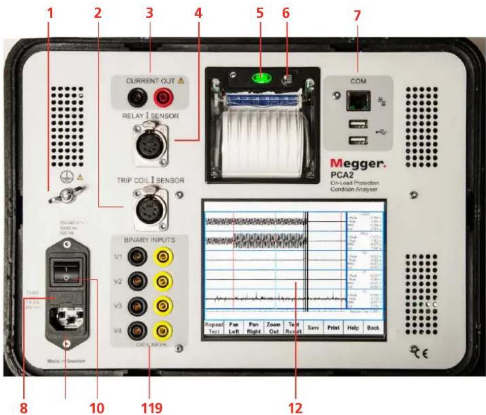
| 1. | ■ Grounding (earth) terminal |
| 2. | ■TRIP COIL I SENSORItc |
| 3. | ■CURRENT OUTThe current out terminals should be connected to the relay or circuit under test |
| 4. | ■RELAY I SENSORIrly |
| 5. | ■Green lamp buttonPower on indicator and button to open the printer paper lid. |
| 6. | ■Print button |
| 7. | ■COMTwo USB and one Ethernet port. The supplied USB flash drive can be connected to either of these USB ports and used for transferring results to a PC. The Ethernet (network) port is not currently utilised. |
| 8. | ■Fuses2 x T 6.3 A, 250 V AC |
| 9. | ■Mains inlet |
| 10. | ■ON/OFF switch |
| 11. | ■ INPUTSV1 V2 V3 V4CAT II 300 VConnect voltages / binary contacts that are to be measured/recorded here, e.g. battery voltage (on V1), relay trip contacts, trip coil voltage, breaker auxiliary contacts etc.Note that these can also be configured to measure and display current if additional current sensors are utilised. |
| 12. | ■ Touch screen Colour LCD |
The PCA2 display

Note Due to continuous improvements to the PCA software and individual configurations, the screenshots depicted will very likely not be identical to that of your own PCA.
| 1. | Standard buttons - these are used to control the PCA |
| 2. | Waveform display window - The input waveforms are displayed here |
| 3. | Dialog Box - Displays important messages from the PCA |
| 4. | Data display boxes - Each waveform has a data display box, indicating the measured results. Tapping an individual channel's data display box brings up a dialog box permitting that channel's displayed amplitude to magnified/reduced and what channels are displayed to be selected. |
Printer setting
Picture below show the deafult settings.
PRINTER SETUP
HEAD TEMP. [°C] = 30.0
HEAD VOLT [V] = 3.4
Data Length: 8 Bits/chr
Parity : None
Handshaking: XON/XOFF
If the settings have been altered by some reason or if you want to check/change the settings, proceed as follows.
1] Set the PCA2 ON/OFF switch to OFF.
2] Touch and hold the Print button while you switch to ON. The PRINTER SETUP printout comes out. Now release the button.
3] The value of a particular menu item can be set or changed by a quick touch on the Print button.
4] Move to the next menu item by pressing the Print button for 2 seconds.
Note If a menu item is wrongly set or missed then the entire process need to be repeated.
4 System settings and configuration
4.1 System mode
Zero DC
Calibration of the RELAY I SENSOR input and the TRIP COIL I SENSOR input.
1] Plugg in all current sensors and touch "Zero DC".

User defaults
Here you can add and edit the test details.
1] Touch "User Defaults".
![Site Name : DICKER MILL Circuit Name : RES EAST Bijit Roy : ALLEYN BOWEN C.T. Ratio Pri. : 200 C.T. Ratio Sec. : 1 Element Tested : L1 Relay Rating : 1A Relay P.S. : -1 ' | 1 | 2 | 3 | 4 | 5 | 6 | 7 | 8 | 9 | 0 | - | = | Bksp % | Q | W | E | R | T | Y | U | I | O | P | [ ] \ | Delete | A | S | D | F | G | H | J | K | L : : ' | Up Caps Off | Z | X | C | V | B | N | M | , . | Down Add | Edit | Help | Print | Ok | Cancel](/content/2026/05/994183/images/718e59230c348e14d4e52baf13f44b254eae1b7dd9cbb5eb7ddf38f357d5a67b.jpg)
2] Touch "Add" for new items
Touch an item to edit and then touch "Edit".
3] Make your settings.
4] Touch "Ok" or "Cancel" to return to the start screen.
Set time
1] Touch "Set Time".
2] Make you settings.
3] Touch "OK.

File manager
Here you manage the files e.g. copy to USB memory.
![[HOME] [14-Jan-2003 19.37.49.000] [14-Jan-2003 19.41.04.000] [14-Jan-2003 19.42.20.000] [14-Jan-2003 20.16.52.000] Example_Results Free: 544.824 (Mb) Total 962.878 (Mb) No USB Disc Found Folder Selected: [14-Jan-2003 19.41.04.000] Modified: 14-Jan-2003 19:41 Delete Move Copy View Print Help Back](/content/2026/05/994183/images/407371e962dfebe25baf0b26c6ce6dd31f3b40a188de915c21bed9ae160df839.jpg)
PCA config
1] Touch "PCA Config".
| + Peak | -0.057 A | ||||
| Peak | -0.032 A | ||||
| RMS | -0.014 A | ||||
| HRLV | |||||
| + Peak | -0.000 A | ||||
| Peak | -0.027 A | ||||
| RMS | -0.005 A | ||||
| HTC | |||||
| + Peak | -0.075 A | ||||
| Peak | -0.021 A | ||||
| RMS | -0.002 A | ||||
| V1 | |||||
| + Peak | -0.994 V | ||||
| Peak | -0.211 V | ||||
| RMS | -0.048 V | ||||
| V2 | |||||
| + Peak | -0.247 V | ||||
| Peak | -0.256 V | ||||
| RMS | -0.037 V | ||||
| CURRENT TO INJECT: 10.0 A/50.0 Hz Injection Time: 0.000 s | |||||
| Zero DC | User Defaults | Set Time | File Manager | PCA Config | Help Back |
2] By double touching any of the lines "Frequency" or "Examine Load" an new window appears and you can make the desired settings.
Frequency : 50 Hz Examine Load : Updated
![1 2 3 4 5 6 7 8 9 0 - = Bksp % Q W E R T Y U I O P [ ] \ Delete A S D F G H J K L ; ' Up Caps Off Z X C V B N M . . Down Add Edit Help Print Ok Cancel](/content/2026/05/994183/images/69dccc85bd21f26c3374962c7d3d8d6e9e9da6ce3fcd18000c5d8edaa633c9a5.jpg)
3] Touch "OK" to return.
![Frequency : 50 Hz Examine Load : Updated PCA config changed, PCA will now restart OK Bksp % Q W E R T Y U I O P [ ] \ Delete A S D F G H J K L ; ' Up Caps Off Z X C V B N M . . Down Add Edit Help PCA Config Ok Cancel](/content/2026/05/994183/images/01fe363fee8f178e75d4ca7c67b5bb4306c051534b9f6da0a5ec4fbb5784d6de.jpg)
Help
The "help" button is alwys available.
1] Touch "Help" to invoke the User guide".
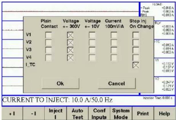
4.2 Configuring inputs
1] Touch "Conf Inputs".
2] Check / uncheck the boxes as desired.
5 On-Load current injection - Principle of operation
5.1 General
The special "On-Load Current Injection" subsystem is able to inject a precise current into a relay element irrespective of the actual load current. This software-controlled current source uses an external feedback element (clip-on hall-effect current sensor) and electronic amplifier. The current source is able to output a precise current (as determined by the external current sensor) even in the presence of other currents (e.g. the secondary current from the protection CT).
This arrangement permits an overcurrent relay within a live/on-load circuit to be injected with a precise current even in the presence of an unknown or varying load current.

flowchart
graph TD
    A["DSP Controller"] --> B["Power Booster"]
    B --> C["Internal Hall Sensor (measures L_out)"]
    C --> D["CT"]
    D --> E["Bushar"]
    B --> F["I_rly"]
    F --> G["Overcurrent Relay"]
    G --> H["I_rly - I_Load + I_Out"]
    H --> I["I_rly Clip-on Current Sensor"]
    I --> J["I_ry"]
    J --> B
    K["Additional Inputs: Voltage Current Contact events Trip Coil Current etc."] --> B
On-Load current injection subsystem block diagram
The on-load current injection subsystem works in the following manner:
User instructions (i.e. current to inject) are supplied to the Computer by use of the touch screen.
■The computer determines the required current waveform sinewave to inject into the relay (starting at a low-to-high zero crossing) and instructs the digital to analogue converter (D/A) accordingly. If a load current is detected then the start of injection is delayed until the next low-to-high zero crossing of the load current. In this way, both the load current and the injected current are started at their low-to-high zero crossings and therefore become synchronised (in-phase). If no load current is detected, then the injection is simply immediately started at a low-to-high zero crossing.
■The D/A controls the power booster/amplifier which outputs a voltage to the Current Out terminals.
■Current flowing into the Relay is then measured with the external clip-on current sensor (Irly).
■The output of the sensor is read by an Analogue to Digital Converter (A/D) and sent to the computer.
■Based on the feedback from the A/D the computer recomputes a new D/A value 20,000 times a second. By means of this feedback system or control loop, the desired current (as seen by the Irly sensor) is injected.
- If there is no load current then the PCA output current will be the same as Irly.
- If there is a load current present then the relay current (as sensed by the Irly sensor) will be the vector sum of the PCA output current and the load current.
5.2 Examining load stage
'Examine Load' refers to the method by which the PCA2 current-source sense uses two different modes to generate.
If 'Updated' is selected (recommended) – The current injection is dynamically corrected while injecting current.
If 'Legacy' is selected - the sense determined by attempting several very short injections (just one cycle long at 50/60). This calculated value is then used for the subsequent current injection. Note: This may cause a relay to prematurely trip.
The updated method was introduced during a software revision and is the recommended default method. Legacy method suffered from sometimes producing very short high current pulses before the main injection that could cause a relay to prematurely trip, hence why the updated method was developed. The capability of reverting to the legacy method is kept to be used in case any unforeseen reason, the user would like to use it.
If for any reason the unit is not able to complete the Examining Load stage then a warning is displayed (Error Examining Load) and the injection aborted. If this error persists, see "4 System settings and configuration" on page 14.
6 Connections for AUTO or MANUAL testing
6.1 Basic connections

IMPORTANT
Always follow the safety regulations in chapter 1 of this manual.
Always comply with local safety regulations.

Basic connections for on-load testing
1] Make connections as shown in the figure above for performing a basic on-load trip test. For a basic on-load injection, only the current out terminals & Irly (RELAY I SENSOR) need be connected.
Note The direction of the relay current sensor does not matter for the injection as the software automatically senses how it has been connected and adjusts accordingly. However, the displayed waveform will always follow the arrow marked on the current sensors so that relative current polarities/phase angles can be measured on the PCA2 display.
Note This sensor must sense the exact same current as the relay.
6.2 Optional connections
1] Additional connections can be made from the other unused PCA2 inputs to various points on a breaker/protection panel: Itc (TRIP COIL I SENSOR) for recording the trip-coil current profile.
Note The polarity of the TRIP COIL I SENSOR does not matter as the software automatically senses how it has been connected and adjusts the display accordingly.
2] V1...Vn. Connect these to voltages/contacts on protection/breaker panel. By connecting to the battery voltage, any dips during protection operation can be measured and battery health inferred.
Note All PCA2 inputs/outputs are galvanically isolated from each other and earth thus simplifying connections. If these inputs are being used to sense a plain or dry contact input, then they must be configured as "Plain Contact" within the software, the default being "Voltage Sensing". This enables a wetting voltage to be output from these inputs so that a plain contact or a dry contact contact can be sensed.
7 Manual test mode
7.1 Performing injections

IMPORTANT
Always follow the safety regulations in chapter 1 of this manual.
Always comply with local safety regulations.
Manual mode is the mode the PCA2 first enters when powered up and after the "Please check all Current..." message is displayed. This mode enables all the inputs to be displayed and measured and simple current injections to be performed.
This display constantly updates any currents or voltages that are connected to the PCA2.
Note This mode is very useful for performing functional checks, quick relay timing tests and confirming connections are correct.

Manual mode - basic screen
7.2 Performing injections / Tests in manual mode
1] If injections are to be performed then connections as per "5.1 - Basic Connections" must be made.
Alternatively, connections as described in or "9. Functional Check Procedure" can be used in the absence of a real load.
2] Select the current to inject for the test using the "+1" and "-1" buttons.
3] Touch the "INJECT I" button when ready to inject.
An "Examining Load" message will briefly appear, if Legacy mode is selected, followed by the injection.
Note The PCA may indicate an error like "Current Out Error" or "A Current error caused the fault to be stopped early". This is usually due to wrong connections. Check that the Current Out terminals are correctly connected to the circuit under test and that the feedback element (Irly, the Relay Current Sensor) is connected to the appropriate location.

line
| Signal | Peak Current (A) | Peak Voltage (V) | |--------|------------------|------------------| | I-OUT | 2.279 | 0.189 | | I-CL | 2.279 | -0.218 |Typical manual mode display showing an injection
Note Current generation over 17 Amps is limited to 20 seconds.
8
Auto test mode
8.1 Basic

IMPORTANT
Always follow the safety regulations in chapter 1 of this manual.
Always comply with local safety regulations.
Auto test mode is used when it is desired to perform a RECORDING test, with or without an injection at the same time.
1] From the basic Manual Test screen, touch "AUTO TEST", the auto test setup screen will appear.
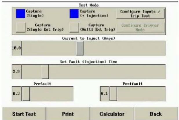
Automatic test setup screen
2] Select "Capture (Single)" for a test that will just record all the currents/voltages/contacts without any injection.
3] Select "Capture (+ Injection)" for a test that will perform a current injection plus record all the currents/voltages/contacts.
4] Select "Configure Inputs / Trip Test" to configure the four voltage/contact inputs as well as define any condition that will stop any injection before its programmed time (e.g. "Stop Inj On Change").

5] Select "Capture (Singel Ext Trig)" for a test that will perform an external trig from a contact, voltage or current on the inputs, to start the record of current/voltage/contacts without any injection.
6] Select "Capture (Multi Ext Trig)" for a test that will perform several external trigs from a contact, voltage or current on the inputs, without any injection.
Configure Trigger Mode

7] Select the "Configure Trigger Mode" to select which input to be set to trig the recording, V1/V2/V3/V4/Itc/Irly. "Smart detect" mode trigger on a change from initial value. Leave smart detected enabled on "Itc" (TRIP COIL I SENSOR) to capture on breaker operation.
8] Select the "Current to Inject (Amps)" value. This is typically set to a multiple of the relay plug setting.
9] Select the "Set Fault (Injection)Time" (i.e. max length of injection). The fault time
should be set to slightly more than the expected relay operate time at the selected current to ensure enough time to operate, even on a sluggish relay.
- Prefault defines how long the PCA2 will record before the injection/fault.
- Postfault defines how long the PCA2 will record after the injection/fault.
- Except for specialist applications, Prefault & Postfault values are usually set to their minimum to reduce storage requirements.
10] When ready, touch "Start". There will be a 10 second countdown before the actual test. This is for safety reason for you to make distance from the breaker. If this is not required simply touch "Start" on the countdown dialog box to immediately start the test).
11] The test will then proceed and the display will look as below.
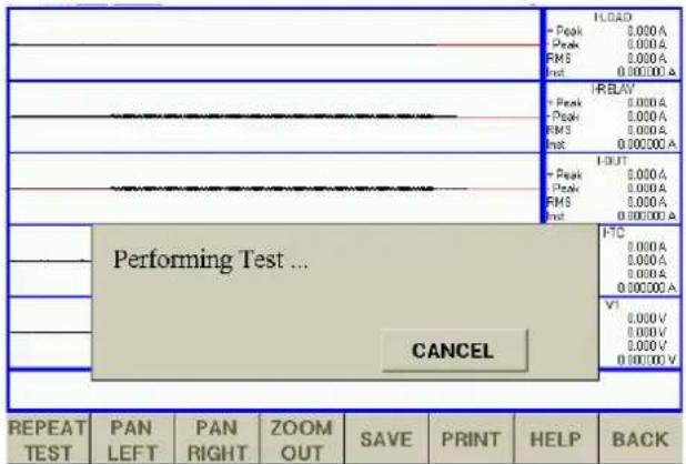
Auto test in progress
8.2 Auto Test mode - Calculator
You are completely free to set up the current level and the maximum time to inject for. In practice it is often desired to inject the relay at a multiple of its plug setting, i.e. 2x, 4x, 5x etc. Also, it is necessary to know what the expected operating time at that current will be so that an injection time in excess of this can be selected.
Available within the "Auto Test" setup window is a relay operation time calculator.
1] Touch the "Calculator" button to bring up the window shown below.
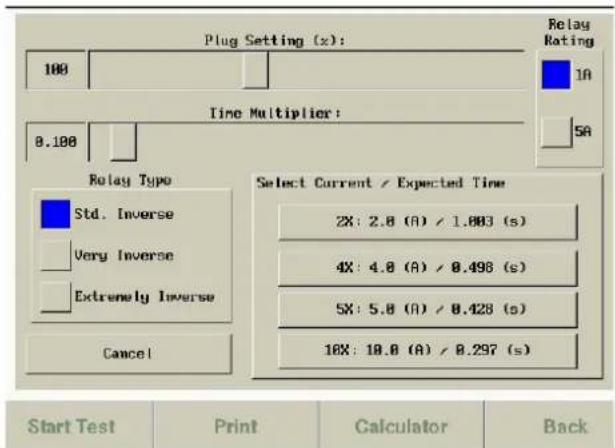
Auto test calculator screen
2] Select the relay rating, plug setting, time multiplier and relay type as required.
3] Then select the plug setting multiplier desired for the injection, this can be 2 times, 4 times, 5 times or 10 times.
Doing this will return to the auto test screen, with the appropriate injection current and fault time (+10% of expected op time is automatically added) values already applied.
4] Touch "Start".
The test will be performed and the test results screen will include the predicted relay operation time and (provided a valid trip coil waveform is recorded), the percentage error from the actual trip time.
8.3 Auto Test mode - Interpretation of graphical results/measurements
Once the test has been completed the PCA will zoom each of the waveforms accordingly in amplitude. Also, the Itc (Trip Coil current) waveform will be automatically inverted if the sensor was connected in reverse - this is so the trip coil waveform always displays the right way up. The results of the test can now be examined.
Figure below shows a set of results with Itc (Trip coil current sensor) connected and V2 connected to the relay trip contact.

line
| Signal | Peak Value | Annotation | |------------|------------|--------------------| | I-LOAD | +0.311 A | | | I-RELAY | +0.084 A | | | I-TC | +0.255 A | | | V1 | +123.665 V | | | V2 | +62.057 V | |Main parts of the automatic test display
The following are of interest:
- Load current collapses (when the breaker trips)
- Injected current from the PCA2 to the relay
- Contact closes (connected to the relay trip contact, can also usefully be connected to trip supply battery, etc.)
- Trip coil current waveform
- Movable cursor
The following actions are possible:
■Zooming in (in time): The user can click on one of the waveforms (but not on the movable cursor) - this will zoom in.
■Zooming in or out (amplitude): Click on one of the data display boxes - this will cause a small popup zoom window to appear. The waveform can then be zoomed in or out.
■Moving the movable cursor: Simply click on the movable cursor and drag it across the touch screen to the new location.
(The data boxes will update as the cursor is moved).

line
| Metric | Value | |--------|-----------| | HLOT | 2.019A | | Peak | 1.715A | | RMS | 1.372A | | HLOT | 1.184540 | | HBLAV | 7.178A | | Peak | 7.178A | | RMS | 5.013A | | HLOT | 4.340658 | | I-OUT | 5.159A | | Peak | 5.493A | | RMS | 3.659A | | HLOT | 3.656158 | | HTC | 0.169A | | Peak | 0.147A | | RMS | 0.159A | | HLOT | 0.158081 | | V1 | 0.188V | | Peak | -0.258V | | RMS | -0.069V | | HLOT | -0.01856* | | REPEAT TEST | PAN LEFT, PAN RIGHT, ZOOM OUT, SAVE, PRINT, HELP, BACKAutomatic test example (zoomed in)
Figure below shows a full test on a protection system. On this occasion, the Trip coil current sensor has been connected. Also the battery voltage has been connected to V1, permitting any dip during a test to be observed and quantified.

line
| Signal | Value | |--------|-----------| | Peak | +0.311 A | | Peak | +0.080 A | | RMS | +0.176 A | | inst | +0.171 A | | I-RELAV| - | | Peak | +0.084 A | | Peak | -0.037 A | | RMS | +0.026 A | | inst | -0.013 A | | I-TC | - | | Peak | +0.255 A | | Peak | -0.137 A | | RMS | +0.179 A | | inst | +0.198 A | | V1 | - | | Peak | +123.665 V| | Peak | +123.427 V| | RMS | +123.523 V| | inst | +123.619 V| | V2 | - | | Peak | +62.057 V| | Peak | +51.460 V| | RMS | +51.632 V| | inst | +51.709 V| Injection Time: 0,000 sAutomatic test with trip coil current

other
| Wave | Label | Value | |------|-------------|-----------| | 1 | Pan Left | 9.08A | | 1 | Zoom Out | 9.08A | | 1 | Print | 1.307A | | 1 | Help | 1.307A | | 2 | Pan Left | 9.08A | | 2 | Zoom Out | 9.08A | | 2 | Print | 1.307A | | 2 | Help | 1.307A | | 3 | Pan Left | 9.08A | | 3 | Zoom Out | 9.08A | | 3 | Print | 1.307A | | 3 | Help | 1.307A |Automatic test with trip coil current (zoomed in)
The following points are of interest:
- Load current collapse point, the breaker has tripped.
- Characteristic Trip Coil Waveform (typical waveform for an Oil circuit breaker shown).
- Measurement taken with moveable measurement cursor at time of Load Current Collapse.
Saving results to a COMTRADE record
1] Click on "Save" to save the result as a COMTRADE record to the internal storage device.
The filename is based on the date and time. These COMTRADE records can be copied from the PCA2 onto a USB stick using the file manager (see later).
8.4 Auto test mode - Auto test analysis
At the end of an auto test, the unit will attempt to analyse the recorded data. It does this by first examining the ltc channel and trying to identify a valid trip coil waveform. If none is found then a message to that effect is shown, note that this is not an error.
To get the most realistic analyze in "Text Result" you can choose from "OCB", "VCB/SF6" or "No Calculation".
OCB Oil Circuit Breaker
VCB/SF6 Vaccum Circuit Breaker or SF6 Circuit Breaker
No Calculation No analyze of the trip coil waveform is made
Failure to identify a valid trip coil waveform can be due to many reasons, most typically wrong connections. If a valid waveform is found then the unit will attempt to identify important features on this as well as other data. The screenshot below shows a typical Auto Test Text Results Screen.
| Test Results Summary | Click on a marker to change its position | |||||||
| ==================== | ||||||||
| TRLY: | 3471.7 | (ms) | IPK1 : | 4.4 | (A dc) | |||
| TRLY_CALC: | 3424.2 | (ms) | IPLT : | 4.7 | (A dc) | |||
| TRLY_ERR : | 1.4 | (%) | VINI : | 123.6 | (V dc) | |||
| LTCH : | 18.6 | (ms) | VMIN : | 120.0 | (V dc) | |||
| BFFR : | 24.4 | (ms) | ||||||
| ACON : | 92.0 | (ms) | ||||||
| END : | 110.3 | (ms) | ||||||
| MCON : | 43.8 | (ms) | ||||||
| Repeat Test | Pan Left | Recalc | Graph Result | Save | Help | Back | ||
1] Touch the "Graph Result" button to show the graphical results.
2] You can adjust the text result value by touching the the value or name.
The "Graph Result" view will appear.
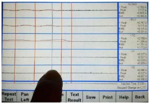
3] Touch the thin vertical line (cursor) and move as desired.
4] After moving the cursor, touch the "Text Result" button to read the updated analyzed value.
| Description of auto test text results | ||
| Automatic measurement name | Description How | calculated |
| TRLY Relay Op time | time Beginning of trip | coil current (I_tc) |
| TRLY_CALC Calculated relay operation. time | operation. time | According to setting in the "Calculator" |
| TRLY_ERR Error | TRLY vs TRLY_CALC | |
| LTCH Trip latch | release time | First dip of I_tc |
| BFFR Time when | TC slug reaches stop | Second dip of I_tc |
| ACON Time the | "a" contact interrupts the TC current | Start of decay of I_tc |
| END Time when | TC current reaches zero | I_tc reaching zero |
| MCON Time of transition of main interrupter contacts | transition of main interrupter contacts | I_load reducing by more than 50% from initial value |
| IPK1 Amplitude | of first current peak | Max I_tc between TRLY and BFFR |
| IPLT | Max current peak | Max I_tc during entire test |
| VIN | Initial battery voltage | Voltage on V1 input just before TRLY |
| VMIN | Minimum battery voltage | Minimum voltage on V1 during entire test |

line
| Test | Peak Amplitude | RMS Amplitude | |------|----------------|---------------| | I-LOAD | +0.350 A | +0.191 A | | I-RELAY | +0.081 A | -0.040 A | | I-TC | +4.690 A | +4.625 A | | V1 | +120.496 V | +120.313 V | | V2 | +119.855 V | +119.626 V |9
Handling results / File manager
9.1 Copying, moving and deleting files
The file manager can be entered by clicking on "SYSTEM MODE", and then on "File Manager". The File Manager is used or copying files to the USB stick, cleaning up the PCA's internal storage and viewing previously saved records.
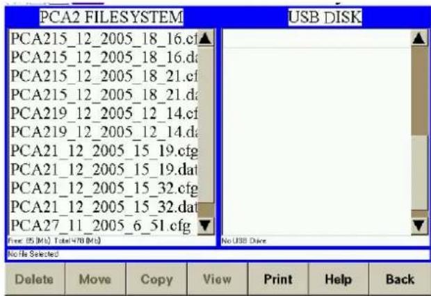
File manager display
Deleting files
1] To delete a file, select it by clicking on the filename. and touch the delete button.
Copying and moving files
Files can only be copied or moved if a USB stick is found in one of the USB ports.
1] Insert a USB stick into one of the USB ports, the USB DISK list box should fill with files that are on the USB stick.
2] Click on the file to be copied or moved.
3] Then click the copy or move button.
(Please note: large files may take some time to copy).
Changing directories
1] To change directories double click on the directory name.
2] Double click on ".." to return to the parent directory.
![PCA2 FILESYSTEM PCA215_12_2005_18_16.cf▲ PCA215_12_2005_18_16.d PCA215_12_2005_18_21.cf PCA215_12_2005_18_21.d PCA219_12_2005_12_14.cf PCA219_12_2005_12_14.d PCA21_12_2005_15_19.cfg PCA21_12_2005_15_19.dat PCA21_12_2005_15_32.cfg PCA21_12_2005_15_32.dat PCA27_11_2005_6_51.cfg File: 8 [Mkt] Total: 470 [Mkt] Selected File /Name/controls/PCA215_12_2005_12_14.dat Bus: 199,000 [yes] Modified: 29 Dec-2005 18/56 Delete Move Copy View Print Help Back](/content/2026/05/994183/images/597812a06f520d4ba041af9d281b48f584d6c8d00951011a55069e11094d5236.jpg)
File manager with usb disk attached
Viewing previously saved COMTRADE records
1] PCA COMTRADE records can be viewed by clicking on the record filename of the .CFG file to highlight it.
2] The View button should then be clicked. The record will be opened with the same display/zoom/printing features available as in the automatic test.
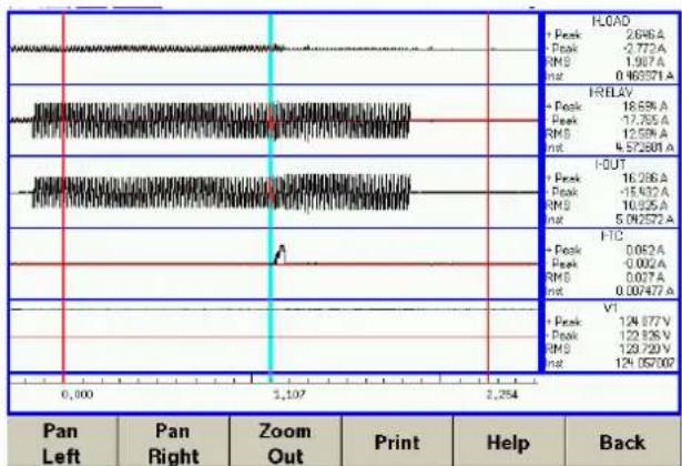
line
| Metric | Value | |------------|---------| | FLOAD | 2.646 A | | PEAK | -2.772 A | | RMS | 1.987 A | | INT | 0.463571 A | | RELAY | 18.59 A | | PEAK | -17.35 A | | RMS | 12.59 A | | INT | 4.572801 A | | I-OUT | 16.286 A | | PEAK | -15.432 A | | RMS | 10.325 A | | INT | 5.04252 A | | FIC | 0.082 A | | PEAK | -0.002 A | | RMS | 0.007 A | | INT | 0.00747 A | | VTI | 124.877 V | | PEAK | 122.826 V | | RMS | 129.720 V | | INT | 124.057002 |Loaded results being displayed
9.2 PC Viewer software
On the USB flash drive, delivered together with the instrument, is a software that can be used for handling the results. The software is easy to use and there are instructions as well.
1] Extract the files from the zipped folder "PCA Viewer".
2] Run the file "PCAViewer.exe
10 Functional check procedure
The following describes a quick functional check to test the main functions of the PCA2. This test should be performed whenever it is desired to check the proper functioning of the PCA2.
1] Make the connections shown below. i.e connect a shorting link to the Current Out terminals.
Plug in Irly (Relay Current Sensor) to the RELAY I SENSOR socket on the front panel and clip this sensor onto the shorting link.

2] Connect the PCA2 to mains and turn it on. The display will briefly turn white then go through the power up sequence.

PCA2 connections
3] Touch the "OK" button on the display.
4] Set the current to (say) 2A by using the the "+I" and "-I" buttons then touch "Inject I" button.
The PCA2 will then (if in "Legacy" mode;
briefly indicate "Examining Load") and then proceed to start the injection.
The display will show a 1 A sinewave (default initial Manual Test current value) for both I_RELAY and I_OUT waveforms.
The above procedure proves that the PCA2 is correctly performing an injection and correctly displaying waveforms and measurements.
11 Specifications
Specifications PCA2
Specifications are subject to change without notice.
Environment
Application field The instrument is intended for use in high-voltage substations and industrial environments.
Temperature
Operating 0°C to +50°C (32°F to +122°F)
Storage & -25°C to +70°C (-13°F to +158°F)
transport
Humidity 5% – 95% RH, non-condensing
Altitude <2000 m (6500 ft)
Pollution degree 2
Overvoltage II
category
CE-marking
LVD 2006/95/IEC in accordance with:
EN/IEC 61010-1: 2010
EN/IEC 61010-2-030: 2010
EMC 2006/95/EC in accordance with:
EN 61326:2006
General
Mains voltage 100-240 ±10% V AC, 50/60 Hz
Powrer consump- 500 VA (max)
tion
Dimensions 274 x 247 x 180 mm
(10.8" × 9.7" × 7.1")
Weight 7 kg (15 lbs)
Isolation Current output, Voltage/Contact inputs & contact outputs are all individually galvanically-isolated from each other and chassis to 1500 V
Interface I/O 15-way connector for add-on accessories/expansion
Interfaces 10/100 Mbs Ethernet
2x USB (for Flash Drive / Ext. Hard Disk / Barcode-reader etc.)
USB Memory Stick: 1Gb supplied as standard
Manual test mode Real-time oscilloscope display with Current/Voltage/Contact Measurements General purpose current source & timer Quick On-Load or Off-Load Injections Overcurrent Relay Testing/Timing
Auto test mode On-Load & Off-Load testing with recoding Timing/Voltage/Current measurements on rec. data Auto Relay/Breaker/Trip Supply results analyses OCB, VCB & SF6 breaker types Trip-Coil analysis
Utilities Results Saving/Transfer to USB drive Software updates via USB drive Online operating manual
Screen VGA (640x480) TFT LCD 256K colours with touch control
Memory 256 Mb RAM, 1Gb Flash (512 Mb available for user storage) Time/Date Real-time clock with 1 year battery backup
Current output
Fully software controlled and regulated.
Injection start synchronised with zero crossing and data recording. During ON-LOAD injections automatically phase-locks (45-65 Hz) and instantly corrects for any load current variation during injection.
Range 0 to 17 A continuous
17 to 25 A max 20 seconds
Resolution 0.001 A
Compliance voltage ±45V peak
Duty cycle 250 VA/10 A (continuous), 500 VA/25 A for 30 s.
Error <0.5% Typ., 1% Max
Distortion <0.2% (DC-1 kHz)
Resolution 0.001 Hz
Frequency error < ±0.005%
Protection & power management Processor continually monitors output for accuracy and waveform quality – any deviation from the programmed value is immediately reported to the user. Fault conditions like over-burden/over-power/over-temperature and open-circuit result in tests being aborted and a warning displayed.
Inputs/Data acquisition
(Voltage/contact inputs can also be used to measure current via additional CT clip-on Hall probes).
Can be used to measure & record any arbitrary voltage or contact (e.g. battery voltage, relay trip contacts, breaker auxiliary contacts on-line or main breaker contacts during off-line testing)
Current inputs
No. of inputs 2x dedicated current inputs (via supplied clip-on 'Hall' sensors)
Trip Coil Current Sensing & Relay Current Sensing/Feedback
Range ±35 Apeak (25 Arms)
Resolution 0.001 A
Measurement +pk, -pk, instantaneous & RMS measurements displayed
Error <0.5% Typ., 1% Max
Resolution 16-bits (15+sign)
Bandwidth DC to 4 kHz
Current probe CP35
Current range 30 A
Output sensitivity 100 mV/A
Frequency range DC to 100 kHz (-0.5 dB)
Resolution ±1 mA
Basic inaccuracy ±1% of reading ±2 mA
Conductor position sensitivity < ±1% relative to centre reading
Phase shift < 2 degrees (up to 1 kHz)
Load impedance > 100 kΩ
Output connection Safety BNC connector
Voltage/Contact inputs
No. of inputs 4x Ultra-flexible galvanically-isolated inputs Selectable as: Voltage / Voltage sense or contact sense
Measurement category CAT II 300 V
Range ±300 Vpeak and ±10 V peak (for transducers/sensors etc.)
Measurement +pk, -pk, Instantaneous & true-RMS measurements displayed
Error <0.2% Typ., 0.4% Max
Resolution 16-bits (15+sign)
Bandwidth DC to 4 kHz
Contact mode
Software selectable as: Voltage sense or contact sense / 2.5-300V Records actual contact voltage over time (not just on/off status). Programmable pre-trigger and post-trigger recording times Protected against incorrect wet/dry selection
Time resolution/sampling rate 10,000 samples/sec (±0.1msec resolution)
Memory 32 Mb memory dedicated to waveform/event acquisition (40 seconds recording for all channels at 10 kHz)
Trigger events Programmable; start & stop recording on any or multiple Voltage/Contact/Current inputs or injection start/stop
A1 Glossary
COMTRADE - IEEE Standard Common Format for Transient Data Exchange (COMTRADE) for Power Systems.
Defined in IEEE C37.111-1991 & IEEE C37.111-1999. A popular file format used to hold oscillographic data.
Note that a COMTRADE record consists of a minimum of two files: a .CFG & a .DAT file. The PCA also uses a .HDR file to hold test data and the results of any automatic analysis on the data. So each PCA result consists of three files (.CFG, .DAT & .HDR), all of which must be copied and stored together.
A2 Using additional current probes
Additional current probes can be connected to the PCA2 to allow it to monitor extra currents during an injection. This is useful as it allows, for example, three phases to be monitored while injecting into one of them.
1] Connect the current probes into the INPUTS (contact / voltage) of the front panel of the PCA2, see figure below.

Additional current probe connected to input V3
Note It is necessary to use the supplied BNC to 4 mm converter to make this connection.
2] In order to correctly interpret the input from a current probe, it is necessary to configure the software to expect it. To do this in manual mode, select the "Conf Inputs" button at the bottom of the screen.
For auto test mode select the "Configure Inputs / Trip Test" button on the auto test setup window, see figure Auto test mode below.

Manual mode

bar
| Category | Value | | -------------------- | ----- | | Injection Style | 2.8 | | Current to Inject (Amps) | 2.8 | | Set Fault (Injection) Time | 4.9 | | Prefault | 1.8 | | Postfault | 1.8 |Auto test mode
3] This will display the configure inputs window, which allows a current input to be selected as shown below in figure below.

Configure inputs
4] Select the relevant input channel (in this case V3) to be a current input and click OK.
This has reconfigured the input to use the correct scaling for a current probe, and has updated the units to be displayed in Amps. However, this is not yet shown, as by default V3 is not displayed.
5] To display V3, simply click on V1 or V2 on the right hand side of the screen.
The channel window will appear allowing you to switch to the display of V3 and V4, see fig. A 5
6] Click on V3/V4.
7] Click on close. The display will then be as shown in fig. A6

A5
| ILOAD | |||||||
| + Peak | +0.060 A | ||||||
| Peak | -0.043 A | ||||||
| RMS | +0.013 A | ||||||
| I RELAY | |||||||
| + Peak | +0.026 A | ||||||
| Peak | -0.057 A | ||||||
| RMS | +0.006 A | ||||||
| -TC | |||||||
| + Peak | +0.028 A | ||||||
| Peak | -0.029 A | ||||||
| RMS | +0.00F A | ||||||
| V3 | |||||||
| + Peak | -0.222 A | ||||||
| Peak | -0.302 A | ||||||
| RMS | +0.296 A | ||||||
| VI | |||||||
| + Peak | +0.073 V | ||||||
| Peak | -0.055 V | ||||||
| RMS | +0.025 V | ||||||
| CURRENT TO INJECT: 2.0 A/50.0 Hz Injection Time: 0.000 s | |||||||
| +1 | -1 | Inject 1 | Auto Test | Conf Inputs | System Mode | Help | |
A6
Probe DC offset
Note that Hall-Effect current probes (as used on the PCA2) always have an inherent DC offset present which varies with temperature. For this reason it is recommended to regularly re-zero the inputs.
1] Select the "System Mode" button at the bottom of the screen.
2] Then select "Zero DC".
Note Make sure that no DC voltages or currents are present otherwise all future measurements will then be offset by these.
Index
A
Additional current probes.... 36
Application examples.... 18
Auto test analysis 26
Auto test mode 22, 26
Auto Test mode - Calculator 23
B
Basic connections.... 18
C
Calculator 23
Changing directories.... 28
Contact information 11
Copying and moving files 28
CURRENT OUT 12
D
Deleting files....28
Display....13
F
File manager.... 28
Functional check procedure 30
G
Glossary 34
Graphical results.... 24
H
Handling results....28
|
Injections ...... 20
Interpretation of graphical results ...... 24
L
Load stage....17
M
Manual test mode....20
0
On-Load current injection 16
Optional connections....19
P
Packing list 11
Panel 12
PC Viewer software....29
Probe DC offset....37
R
RELAY I SENSOR....12
s
Safety 6
Saving results to a COMTRADE record ..... 25
Service/Technical support.... 11
Specifications 32
Symbols on the instrument....6
T
TRIP COIL I SENSOR....12
W
Warranty statement 10
Your "One Stop" Source for all your electrical test equipment needs
■Battery Test Equipment
■Cable Fault Locating Equipment
■Circuit Breaker Test Equipment
■Data Communications Test Equipment
■Fiber Optic Test Equipment
■Ground Resistance Test Equipment
■Insulation Power Factor (C&DF) Test Equipment
■Insulation Resistance Test Equipment
■Line Testing Equipment
■Low Resistance Ohmmeters
■Motor & Phase Rotation Test Equipment
■Multimeters
■Oil Test Equipment
■Portable Appliance & Tool Testers
■Power Quality Instruments
■Recloser Test Equipment
■Relay Test Equipment
■T1 Network Test Equipment
■Tachometers & Speed Measuring Instruments
■TDR Test Equipment
■Transformer Test Equipment
■Transmission Impairment Test Equipment
■Watthour Meter Test Equipment
■STATES® Terminal Blocks & Test Switches
■Professional Hands-On Technical and Safety Training Programs
Megger is a leading global manufacturer and supplier of test and measurement instruments used within the electric power, building wiring and telecommunication industries.
With research, engineering and manufacturing facilities in the USA, UK, Germany and Sweden, combined with sales and technical support in most countries, Megger is uniquely placed to meet the needs of its customers worldwide.
Megger is certified according to ISO 9001 and 14001. Megger is a registered trademark.
Megger Group Limited UNITED KINGDOM Dover, Kent CT17 9EN ENGLAND
| AUSTRALIA | PHILIPPINES |
| BULGARIA | POLAND |
| CANADA | ROMANIA |
| CZECH REPUBLIC | RUSSIA |
| CHINA | SINGAPORE |
| FRANCE | SLOVAK REPUBLIC |
| GERMANY | SOUTH AFRICA |
| HUNGARY | SPAIN |
| INDIA | SWEDEN |
| INDONESIA | SWITZERLAND |
| JAPAN | TAIWAN |
| KINGDOM OF BAHRAIN | THAILAND |
| KOREA | UNITED ARAB EMIRATES |
| MALAYSIA | USA |
| PAKISTAN | VIETNAM |
CE
Megger
R
WWW.MEGGER.COM
Postal address:
Megger Sweden AB
Box 724
SE-182 17 DANDERYD
SWEDEN
Visiting address:
Megger Sweden AB
Rinkebyvägen 19
SE-182 36 DANDERYD
SWEDEN
T +46 8 510 195 00
F +46 8 510 195 95
seinfo@megger.com
www.megger.com
- Contents
- Safety....6
- Introduction......10
- System settings and configuration....14
- On-Load current injection - Principle of operation....16
- Connections for AUTO or MANUAL testing....18
- Manual test mode....20
- Auto test mode 22
- Handling results / File manager .....28
- PC Viewer software .....29
- Functional check procedure ...... 30
- Specifications 32
- A1 Glossary ....34
- A2 Using additional current probes ..... 36
- Index 38
- Safety
- General
- Symbols on the instrument
- Safety instructions
- Read / Follow / Retain all instructions
- Connecting
- Grounding (Earthing)
- Mains cord protective conductor
- Separate ground wire
- Placement
- Use
- EMC Warning
- Cables
- Power sources
- Inputs and outputs
- Ventilation
- Lightning
- Cleaning
- Damage
- Damage requiring service
- Servicing
- Returning
- 2
- Introduction
- General
- Warranty statement
- Service/Technical support
- Unpack system
- 3
- Panel
- The PCA2 display
- Printer setting
- PRINTER SETUP
- System settings and configuration
- System mode
- Zero DC
- User defaults
- Set time
- File manager
- PCA config
- Help
- Configuring inputs
- On-Load current injection - Principle of operation
- General
- Examining load stage
- Connections for AUTO or MANUAL testing
- Basic connections
- IMPORTANT
- Optional connections
- Manual test mode
- Performing injections
- Performing injections / Tests in manual mode
- 8
- Auto test mode
- Basic
- Auto Test mode - Calculator
- Auto Test mode - Interpretation of graphical results/measurements
- The following actions are possible:
- Saving results to a COMTRADE record
- Auto test mode - Auto test analysis
- 9
- Handling results / File manager
- Copying, moving and deleting files
- Deleting files
- Copying and moving files
- Changing directories
- Viewing previously saved COMTRADE records
- PC Viewer software
- Functional check procedure
- Specifications
- Specifications PCA2
- Environment
- CE-marking
- General
- Current output
- Inputs/Data acquisition
- Current inputs
- Current probe CP35
- Voltage/Contact inputs
- Contact mode
- A1 Glossary
- A2 Using additional current probes
- Probe DC offset
- Index
- A
- B
- C
- D
- F
- G
- H
- |
- L
- M
- 0
- P
- R
- s
- T
- W
- Your "One Stop" Source for all your electrical test equipment needs
- Megger
Brand : Megger
Model : PCA2
Category : Measurement