AD610 - Uncategorized Tema - Free user manual and instructions
Find the device manual for free AD610 Tema in PDF.


| Product Type | VoIP SIP Multifunction Interface for PA Amplifiers |
| Dimensions | 74 x 58 x 25 mm |
| Weight | 170 g |
| Power Supply | PoE (802.3af class 0, 12.95W) or external 230Vac/12-24Vdc-1A |
| Network Interface | 10/100BaseTx Ethernet, RJ45, PoE |
| Audio Outputs | Isolated transformer output (600 ohm, 2Vpp) + 2W Class-D speaker output (4 ohm) |
| Relay Output | 1 relay, max 30Vdc/1.5A |
| Alarm Input | 1 external contact input (voltage-free) |
| Audio Codecs | G.711μ, G.711a, G.722, L16 (16-44 kHz) |
| Multicast Channels | Up to 5 RX multicast channels with priority levels |
| Message Storage | Micro-SD flash (2GB), pre-recorded messages (WAV 8kHz 16-bit mono), up to 16h audio |
| Protocols | SIP 2.0 (RFC 3261), P2P, Multicast RTP |
| Management | Web interface (password protected), firmware update via LAN |
| Mounting Options | Wall, table, DIN rail (kit included) |
| Operating Temperature | -20°C to +55°C |
| Storage Temperature | -20°C to +65°C |
| Humidity | Up to 95% non-condensing |
| Safety & Compliance | CE, RoHS, WEEE |
| Warranty | 2 years (extension possible) |
| Maintenance | Web-based firmware updates, backup/restore configuration, factory reset |
| Cleaning | Protect from dust, humidity, and chemicals; do not expose to direct sunlight or heat |
| Spare Parts & Repairs | Use only original Tema parts; repairs by Tema Telecomunicazioni only |
Frequently Asked Questions - AD610 Tema
User questions about AD610 Tema
0 question about this device. Answer the ones you know or ask your own.
Ask a new question about this device
Download the instructions for your Uncategorized in PDF format for free! Find your manual AD610 - Tema and take your electronic device back in hand. On this page are published all the documents necessary for the use of your device. AD610 by Tema.
USER MANUAL AD610 Tema
"IP COMMUNICATION AND SECURITY COMPANY"
WWW.TEMATLC.IT
AD610
VoIP SIP Multifunction Interface for PA Amplifiers
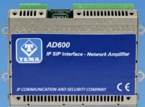
Audio Over IP Network Series
"SlpComStage"
Products for VoIP SIP LAN networking Communications, Paging Amplifiers Systems and Audio Applications. Zone Announcements, Night Ringer, Multicast general call, Background music, Standard SIP call or Emergency call, SD memory with pre-recorded messages, Relays for LAN drives.
PRODUCT MANUAL
Version HW 1.0 - Version SW 1.10

| Revision | Date | Revision reason | Prepared | Checked/Approved |
| 3 21/02/2018 Update MM, DP DP, FL | ||||

DECLARATION OF CONFORMITY CE
We, TEMA TELECOMUNICAZIONI SRL Via C. Girardengo, 1/4 - 20161 MILANO
declare under our sole responsibility that the product:
Product name IP SIP VoIP PoE Network Amplifier
Trade name TEMA TELECOMUNICAZIONI Srl
Type or model AD610
and accessories --
to which this declaration relates is in conformity with the essential requirements and other relevant requirements of the R&TTE Directive (1999/5/EC, 2006/95/EC, 2004/108/EC).
The product is in conformity with the followings standards and/or other normative documents:
HEALT & SAFETY EN 60950-1:2006 +A11:2009 +A1:2010 +A12:2011
EMC EN 55022:2010, EN 55024:2010, EN 61000-3-2:2006
EN 61000-3-3 :2008
MILANO, 20 January 2017
The crossed-out wheeled bin symbol below indicates that this electronic equipment is intended to be disposed in a separate collection and not in an unsorted municipal waste, in order to provide for the treatment of WEEE (Waste Electrical and Electronic Equipment) using best available recovery and recycling techniques. Specific treatment for WEEE is indispensable in order to avoid the dispersion of pollutants and other hazardous substances into the waste stream, while recycling leads to reduction of disposal of waste and the negative impacts on environment and human health. That is, priority is given to reuse of WEEE in its components, subassemblies and consumables. As the final holder, the user has an important role in contributing to reuse, recycling and other forms of recovery of WEEE and is responsible to return this waste in the collection facilities set up by EC Member States and to fulfill other duties in compliance with Directive 2002/96/EC and local laws.

natural_image
Symbol of a trash bin crossed with a diagonal line, representing waste sorting or disposal (no text or labels)
- It is recommended to read this entire manual before proceeding to the installation of the device.
- The installation and commissioning of the device can only be performed by specialized technicians.
- The device is accurately manufactured and tested. In any case, the product is not recommended for use where an error of operations can cause property damage and/or injury to persons.
- It is expressly not recommended maintenance inside the device which must be carried out by Tema Telecomunicazioni, the removal of the closures will invalidate the warranty and makes accessible internal parts with risk of electric shock.
- Tema Telecomunicazioni accepts no responsibility for damage to property and/or persons resulting from incorrect use of the equipment or by procedures that do not comply with the instructions in this manual. Tema Telecomunicazioni reserves the right to make modification to the technical and functional specifications at any time and without any notice.
- Products powered via PoE (Power over Ethernet) may only be connected with cables coming from the internal network company (inside the building), are not allowed connections LAN cables coming from outside the building.
- Use for this device only and exclusively original spare parts and consumables supplied by Tema Telecomunicazioni. The company is not responsible for damage caused by the use of materials not supplied by the same.
- Do not expose the unit to direct sunlight, protect from heat, dust, humidity and chemicals.
- Tema Telecomunicazioni reserves the right to vary the product characteristics for improvement without prior notice. Check the WWW.TEMATLC.IT website for any updates to the latest firmware, manuals, and technical documentation.
- This document is property of Tema Telecomunicazioni, It is forbidden any duplication and reproduction, even partial, as well as storage on any medium without written permission of Tema Telecomunicazioni.

This symbol in the descriptions indicates a general warning or a damage danger to equipment or people.

This symbol in the descriptions indicates useful information or a suggestion for the optimization of the device functionality.
INDEX
PAGE
-
PRESENTATION .... 5
-
FEATURES....7
-
PACKING LIST 8
-
TECHNICAL SPECIFICATIONS....8
-
OPERATION....9
5.1. DEVICE CONNECTION DIAGRAMS....9
- OPERATING MODES.... 10
6.1. CALLS TO AD610....10
6.2. RELAY FUNCTION....10
6.3. CALLS GENERATED FOR ACQUISITION OF EXTERNAL CONTACTS FOR SPECIAL SIGNALINGS.... 10
6.4. MULTICAST AUDIO STREAMING....11
-
COMMANDS AND CODES.... 11
-
INSTALLATION OF THE DEVICE 12
8.1. MOUNTING AND SYSTEM POSITIONING....12
8.2. CONNECTION 12
- PROGRAMMING 14
9.1. PREPARATION FOR THE SYSTEM PARAMETERS PROGRAMMING.... 14
9.2. ACCESS TO PROGRAMMING....16
9.3. NETWORK PARAMETERS....16
9.4. SIP PARAMETERS....17
9.5. GENERAL PARAMETERS....18
9.6. RELAY AND ALARM INPUT SETTINGS.... 19
9.7. CALL BUTTONS....19
9.8. MESSAGES MANAGEMENT....20
9.9. AUTOMATIC ANNOUNCEMENTS....21
- MAINTENANCE 23
10.1. SYSTEM 23
10.2. LOGIN CREDENTIALS....24
10.3. DIAGNOSTIC LOGS 24
- PRESENTATION AND USE OF THE "AA Video Console" SOFTWARE 25
11.1. PRESENTATION....25
11.2. SOFTWARE CONFIGURATION FOR SIP SERVER MODE 26
11.3. SOFTWARE CONFIGURATION FOR PEER-TO-PEER MODE 27
- Introduction to AA-Video Console APP version for operating systems iOS.... 28
12.1. DOWNLOADING AND INSTALLING THE APP 28
12.2. USING THE APPLICATION 30
- Introduction to AA-Video Console APP version for ANDROID systems 30
13.1. DOWNLOADING AND INSTALLING THE APP 30
13.2. USING THE APPLICATION 32
- APPENDIXES....34
14.1. APPENDIX 1: OTHER EXAMPLES OF MULTICAST AUDIOSTREAMING APPLICATIONS 34
14.2. APPENDIX 2: USE OF THE VLC MEDIA PLAYER SOFTWARE AS A MULTICASTENCODER FOR AUDIO FILES.... 36
14.3. APPENDIX 3: USE OF THE AUDACITY SOFTWARE FOR AUDIO FILES RECORDING 37
14.4. APPENDIX 4: CABLING OF A UTP RJ45 NETWORK CABLE ACCORDING TO THE STANDARD EIA568B.... 38
1. PRESENTATION
AD610 adapts a generic Paging audio amplifier sound system to a LAN network with SIP IP-PBX in order to be able to play announcements from any phone on the internal network and any technology.
The access can be authorized by password code to be entered before starting the announcement. It is possible to activate an internal relay for the duration of the announcement to the external amplifier to report the event. The programming of AD610 takes place remotely via LAN thanks to the integrated web server in the device.
AD610 has an isolated analog output with transformer to drive external amplifiers for PA and a second auxiliary output service to connect locally a low power speaker. There are other models of the line as: AD611 which incorporates an efficient 10W (2x5W) Class-D amplifier and AD612 has a max 40W (2x20W) amplifier in Class-D. Both AD611 and AD612 have not an analog audio output driven by isolating transformer, having a built-in amplifier, but are able to directly drive passive speakers.
2nd SIP Account – Night Ringer. AD610 can be registered on the PBX with a second telephone number, different from the one used for ads and inserted in the night ring group. To the arrival of an incoming call, the system plays a sound (user selectable) to all the network speakers. The volume can be adjusted independently of the others managed audio channels.
Amplifier failure detection. AD610 has an input used to the detection of a fault signal from the amplifier, in which case it shall make a SIP call to a programmed number and inform with a special voice event message. The signaling can be repeated a number of times programmable, the operator can stop the sequence with a keyboard code.
Multicast Audio Streaming for music and announcements diffusion. AD610 handles up to 5 multicast channels in LAN with priority levels to allow the background music broadcasting on loudspeakers network. The generation of musical programs in streaming audio can be managed from a PC of the LAN/WAN network with special software or special TEMA Encoder. The background music is muted in the presence of a service announcement.
Service "SIP Security Info Call" - Emergency SIP Call. By connecting a button or an external contact, AD610 can call a phone number programmed to alert the event with a specific warning message. It is a security service for emergencies or simple request for help and information, and allows a one-way phone call.
Total remote management via LAN, integrated Web Server. Programming, configuration, loading and listening to audio files, firmware release update, audio volume adjustment, backup and restore the configuration, device reboot.
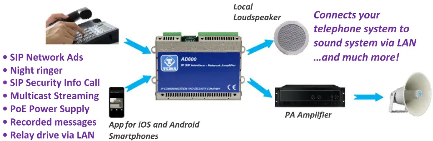
flowchart
graph TD
    A["Local Loudspeaker"] --> B["AD600"]
    C["App for iOS and Android Smartphones"] --> B
    D["PA Amplifier"] --> B
    E["SIP Network Ads"] --> B
    F["Night ringer"] --> B
    G["SIP Security Info Call"] --> B
    H["Multicast Streaming"] --> B
    I["PoE Power Supply"] --> B
    J["Recorded messages"] --> B
    K["Relay drive via LAN"] --> B
    L["Connects your telephone system to sound system via LAN ...and much more!"]
Tested with most popular PBX brands: SIEMENS - AVAYA - ALCATEL - PANASONIC - SAMSUNG - NEC - 3CX LG - WILDIX - AASTRA - ASCOM - NITSUKO - SELTA - PHILIPS ASTERISK BASED SYSTEMS
VoIP SIP Amplifiers-Speakers Products and Accessories of the AD600 "SipComStage" series
AD630 IP-SIP PoE 25W Horn Speaker with 40W internal amplifier (2x20W) IP65 protection.
AD635 IP-SIP PoE 12W speaker for wall mounting with the possibility of integrating a PoE injector adapter.
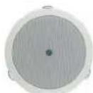
AD633 IP-SIP speaker 12W PoE open-to-ceiling version.
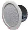
AD633C SIP IP-12W PoE Speaker ceiling version with IP54 flameproof cover.
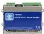
AD610 2X2W PoE IPSIP Amplifier Module External Amplifier Adapter with Sound Isolation Transformer. Directly pilot external power amplifiers or 8 Ohm external passive speakers.
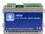
AD611 IP-SIP PoE 10W Amplifier Module (2X5W). Directly pilot 8 Ohm external passive speakers.
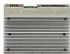
AD612 IP-SIP PoE 40W (2x20W) Amplifier Module when powered with an external power supply. Directly pilot 8 Ohm external passive speakers.
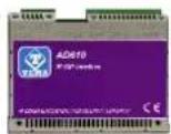
AD615/S Audio Encoder Module from analog to digital on LAN Network in Multicast/Broadcast Channels.
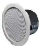
AD333/12XTP Passive 8 Ohm 12W speaker with anti-flame cover (AD333/12TP without cover), internal transformer for 100V audio line. Ideal for connecting to AD610-611-612 or as 2nd speaker to the AD63x series IP-SIP speakers.
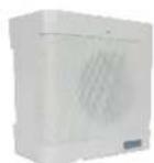
AD335/06TP Passive 8 Ohm 6W speaker with 100V audio line transformer. Ideal for connecting to AD610-611-612 or as 2nd speaker to the AD63x series IP-SIP speakers.
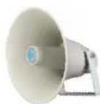
AD330/25T Passive horn speaker 25W 8 ohm with transformer for 100V audio line. Idea for connecting to the AD610-611-612 modules or as 2nd speaker for AD63x IP-SIP speakers series.
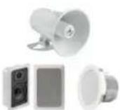
AD330/xx Are available Speakers of different power, Horns and Loudspeakers for flush and ceiling mount.

AA-39DL
Plug Power Supply 220Vac/12Vdc-1,0A.
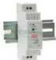
AA-39D1A
DIN Power Supply 220Vac/15Vdc-1,0A.
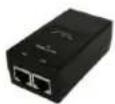
AA-39P4
PoE injector 230Vac/48Vdc 0,5A.
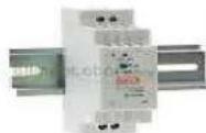
AA-39E3 /-E6V
DIN Power Supplies 220Vac/24Vdc-1,5A 220Vac/24Vdc-2,5A.
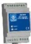
AD301R 30W analog amplifier, 2 channels, Volume-High-Low +/-12dB controls
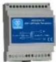
AD320/30 PA 100V audio line transformer 30W, constant voltage, high efficiency toroidal type with low magnetic flux leakage.
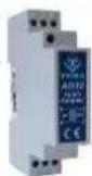
AD32 Isolation transformer, balanced, mixer, attenuator, audio signal filter, low impedance output. Ideal for decoupling devices of audio sources to other amplifiers to eliminate noises.
AA-36 Protected Power Relay Actuator 250Vac/16A/4KVA, command in AC/DC 12V/24V, 1 contact, Led, contacts protected by electric arcs. Ideal for driving loads up to 4.000W.

AA-699xxx Flash lights with Xeon lamp or high brightness LEDs. Ideal to be controlled by the relay of the IP-SIP speakers of the AD630 series or by the IP-SIP amplifier AD610, AD611, AD612 modules, with a call in progress add a light signal to the acoustic signal.


2. FEATURES
- Isolated audio output transformer for 600 ohm amplifiers, output for local monitor loudspeaker output 2W
- 5 RX Multicast Channels for Music/Ads/Messages diffusion with priority levels
- Possibility of diffusing a pre-recorded announcement, associated with the available input, or up to six ads placing a call and send the respective code via telephone
• Acquisition of a system's external contact and warning service with dedicated announcements
- SIP Security Info Call warning/emergency telephone call, sending of pre-recorded messages on loudspeakers
• Detection input for external fault signal amplifier
• Independent adjustment of audio volumes
- SD memory card with audio files from 16sec. customizable by the user (opt. up to 960min. - 16h audio)
- Great versatility with ease of use and programming
- Can be connected to any type of PA amplifier on the market using supplied adapters
- 1 relay for enabling amplifier PA or remote controlled via LAN
- Compatibility with all IP-PBX of the most prestigious brands
- Possibility to register a second SIP account for the "Night Ringer" feature
• P2P (Peer to Peer) operation without IP-PBX
• VoIP connection with SIP protocol both in SIP Proxy Server and Peer-to-Peer mode
• Power supply via PoE (Power over Ethernet) or external power supply, at the same time
- Programming via the Web Interface with password protection
- Possibility of software / firmware update via LAN
- Integration with the local LAN, 100BaseT Ethernet LAN port with RJ45 connector
- Integrated 802.af PoE, a single UTP cable for connection
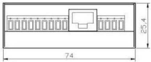
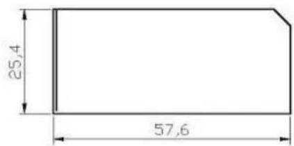
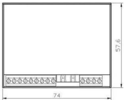
• Extremely compact dimensions 74 x 58 x 25 mm
• Wall mounting, table/shelf and DIN rail
- Possibility of receiving and sending MULTICAST RTP audio streaming, for paging audio announcements, up to 16 priority levels (in reception) and with different volumes for each channel
• Audio streaming with high quality codecs
- Possibility of diffusing pre-recorded announcements at pre-established times (up to 5 for each day of the week)
- Possibility of diffusing a pre-recorded daily announcement, at a set time or manually controlled, with programmable interval and repetitions
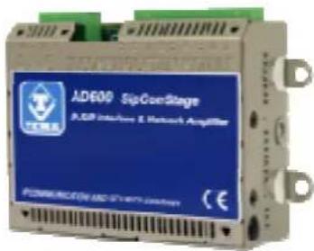
AD610 views and dimensions
3. PACKING LIST
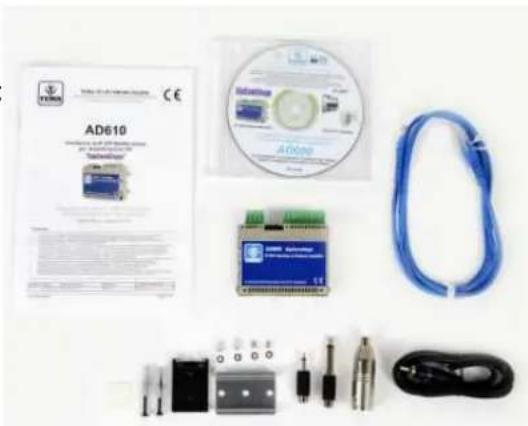
The system is supplied with the parts included in the following list:
• One AD610 device
• System documentation manual (This manual)
• A CD-ROM with complete documentation
• UTP Patch Cord LAN cable 1.5 meters
- DIN rail kit (plastic adapter, 2 screws and 2 washers for fixing the unit, DIN bracket, 2 dowels and screws)
• 4 self-adhesive foots for table or shelf resting
• Audio output cable on terminal block with RCA male plug
• RCA adapter female / male Jack mono 6.3 mm
• RCA adapter female / male Jack 3.5 mm
• RCA adapter female / male XLR
natural_image
Product display of AD610 electronic device including CD, controller, and connectors (no visible text or symbols on main components)4. TECHNICAL SPECIFICATIONS
| LAN | TCP/IP Network 10/100BaseTx |
| Protocols | SIP 2.0, RFC 3261 |
| Power Supply | PoE, PoE Injector and/or external Ac/Dc power supply |
| PoE | 802.3af class 0 12,95W |
| External Power Supply (Opt.) | 230Vac/12-24Vdc-1A |
| Connection | SIP Server (IP-PBX) or P2P (Peer To Peer) |
| Messages/Sounds | prerecorded in the internal SD memory carc |
| Audio File Format | Windows .wav - 8K - 16 bit |
| Duration | 16sec each. Standard (Option up to 960 min16H audio) |
| Technology | IMX25 400MHz microprocessor |
| Memory | 256MB Ram, Micro-SD Flash 2GE |
| Relay contacts capacity | max 30Vdc - 1,5A |
| Internal Audio Amplifier | 2W Class-D |
| Impedance | 4 Ohm |
| 2nd audio output transformer isolated | 2Vpp - 600 Ohm |
| Bandwidth | 80Hz - 20KHz |
| Audio communication | Monodirectional |
| RTP Multicast audio Streaming | G711μ, G711a, G722, L16 from 16 to 44 kHz |
| Inputs from buttons or external commands | 1 |
| Acoustic signalings | Call tone, Ding-dong |
| APP for Smartphones | iOS, Android |
| Programming | practical Web interface and password |
| Installation | wall, table, standard DIN rail |
| Storage temperature | from -20° to +65°C |
| Operating temperature | from -20° to +55°C |
| Relative humidity | 95% non-condensing |
| Dimensions | 74x58x25mm |
| Weight | 170gr |
| Warranty | 2 years, possibility of extension (Option) |
| Compatibility | CE, ROHS |
5. OPERATION
Once correctly programmed, in stand-by, the system waits for incoming calls.
The operator who want to make an announcement on the device will make a call, from any extension of the PBX, to the number to which the device is registered or to its IP address in the case of Peer-to-Peer connection.
The system, according to the desired setting, can activate an output relay contact, for example to signal to the PA amplifier connected to him to take action for the emission of the ad.
The device also allows the sound diffusion in a "streaming" Multicast. In this case the network RTP audio will be diffused to the speakers connected to the system. Unlike the ad mode of direct dialing, in multicast mode, multiple devices can diffuse the same message at the same time, useful for general pre-recorded announcements or for background music.
The changing state of an input interrupt is always monitored to which it is possible to assign a number to call and a message to be played to the called party answers.
It is possible to make the common level adjustment issued of the loudspeakers to better adapt to the acoustic characteristics of the served area.
5.1. Device connection diagrams
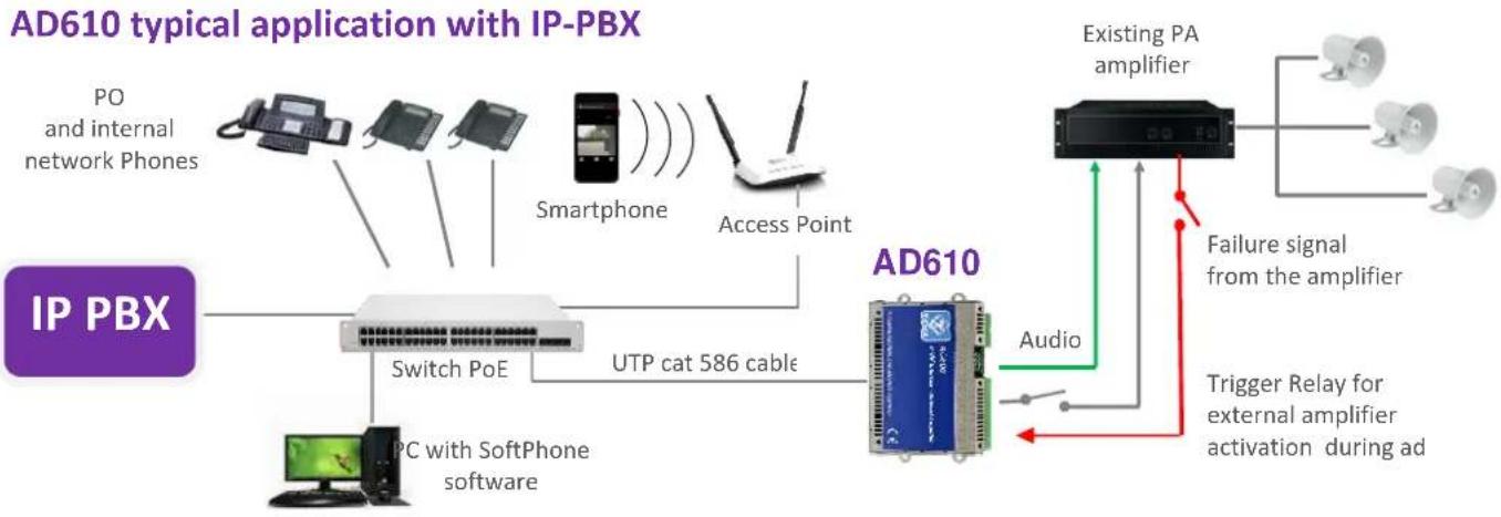
flowchart
graph TD
    A["IP PBX"] --> B["Switch PoE"]
    B --> C["UTP cat 586 cable"]
    C --> D["AD610"]
    D --> E["Audio"]
    D --> F["Existing PA amplifier"]
    F --> G["Failure signal from the amplifier"]
    F --> H["Trigger Relay for external amplifier activation during ad"]
    I["PO and internal network Phones"] --> B
    J["Smartphone"] --> B
    K["Access Point"] --> D
    L["IPC with SoftPhone software"] --> B
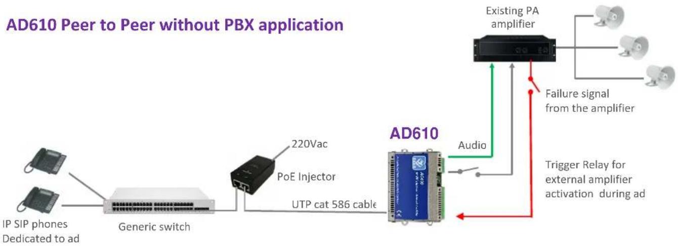
flowchart
graph LR
    A["IP SIP phones Dedicated to ad"] --> B["Generic switch"]
    C["220Vac"] --> D["PoE Injector"]
    D --> E["UTP cat 586 cable"]
    E --> F["AD610"]
    F --> G["Existing PA amplifier"]
    G --> H["Failure signal from the amplifier"]
    F --> I["Audio"]
    I --> J["Trigger Relay for external amplifier activation during ad"]
6. OPERATING MODES
6.1. Calls to AD610
Call from the PBX phones to the AD610 system allows to make announcements to the network speaker. However, it is a normal telephone call, but one-way, so you will not hear the sound present in the vicinity of the device which is not equipped with a microphone. Calling the extension number connected to the AD610 system, it will answer after a set time. It is also possible to have an appropriate code to protect the function from unauthorized access. Hang up to end the announcement. Any background music will be automatically restored.
6.2. RELAY function
The relay typically is used to signal to the PA amplifier connected downstream of AD610 to activate for each message output. If not used for the function described above, the relay is available and controlled with an appropriate code from the caller's telephone.
6.3. Calls generated for acquisition of external contacts for special signalings
Are the calls that the system generates on his line to alert after triggering the alarm by the equipment input contact connected (typically the PA amplifier or a button available to users in the proximity of the device). At the answer it is played to the called a pre-recorded message. It is possible to assign a phone number or an IP address that will be called when the input is activated. It is possible to determine the activation status of the same. It is the closure of the external contact that triggers the sequence of signaling but it is also possible to reverse this logic, in this way the signaling can take place after the opening of the contact (normally closed) connected to the input.
AD610 continuously monitors the status of the contact in the event of the condition of the activation stored on non-volatile memory card and begin to call the person who will manage the situation found at the telephone number programmed reproducing the message associated with the event. It is also possible to choose to play on a local speaker and on any connected audio output a pre-recorded message, which will be played prior to the call to alert the present persons in the area served by the system detected event. It is possible to define an acquisition/silencing code of alarm signaling that the called must type to inform AD610 of the alarm acknowledgment. If the called number is busy or does not reply, or in any other case where AD610 does not receive the capture/acknowledgment code, at the end of each call attempt AD610 return in standby and prepares itself for a new alarm notification
When AD610 receives the correct acquisition/acknowledgment code related to the alarm in progress, the alter signaling will stop and will not be carried out further alarm notification calls. In order to be ready again, it is necessary that the condition which had triggered the previous notification returns in standby. Only at the occurrence of a new activation of the contact condition the calls cycle with the alert notification will start again. In practice: if a connected contact is closed and it is detected its activation, AD610 starts to make warning calls.
In the event that the person called by the system answers and successfully enter the acknowledge code, the alert calls will be terminated. If the contact that had triggered the alert, however, remained closed (this obviously depends by the external device that controls the contact) will NOT be triggered another warning cycle! To have new alerts for this contact, it is necessary that come back in standby before (reopening) and then to its new next possible closure will be detected from AD610 system with new telephone alerts.
6.4. Multicast Audio Streaming
In a LAN network, the Multicast term indicates the possibility to distribute an information like data, audio or video, to a group of IP terminals of the Ethernet network. For Multicast are used class D IP addresses and they range from 224.x.x.x to 239.x.x.x. In our case the AD600 system is able to receive audio in Multicast into the specific IP channel and play it on his speaker and on his audio output for external PA amplifier. The audio can be generated from a PC software application (for example VLC) or by a IP SIP phone. The received audio stream is played without the intervention of any operator, this function is useful for playing back voice messages and information or emergency announcements (also called "Paging" mode). Obviously the Multicast audio streaming is unidirectional, the audio stream is sent from source to destination, but not vice-versa. The audio stream can be sent simultaneously to multiple AD610 terminals (same IP Multicast), or only to distinct terminals (each provided with its own IP address). It is possible to program up to 16 audio receive addresses, each with its own priority and its playback volume, so that the same terminal, if it is already playing audio (eg music) can be interrupted by a higher priority stream (for example an announcement) and with a different volume (typically an announcement must be played at a higher volume than background music). The audio supported by this mode is in the G.711 format (aLaw or μLaw), G722 or linear high quality 16 bit (proprietary format, diffused through the AD615 device or another AA-540).
Example 1
In a plant, there are two systems, connected to the same network switch. From a suitable phone, it is possible to make a voice announcement via multicast address 239.255.12.42:
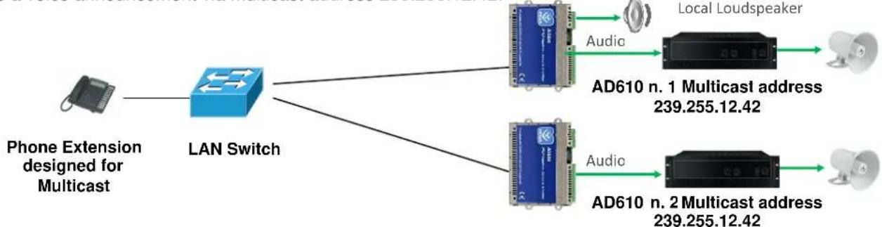
flowchart
graph TD
    A["Phone Extension designed for Multicast"] --> B["LAN Switch"]
    B --> C["AD610 n. 1 Multicast address 239.255.12.42"]
    B --> D["AD610 n. 2 Multicast address 239.255.12.42"]
    C --> E["Local Loudspeaker"]
    D --> F["Local Loudspeaker"]
    C --> G["Audio"]
    D --> H["Audio"]
Both systems will play the announcement audio message. Many more devices than those given in the example can be connected, since there are no limits.
Example 2
In the plant there are two systems with different Multicast addresses.
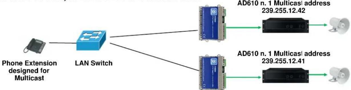
flowchart
graph TD
    A["Phone Extension designed for Multicast"] --> B["LAN Switch"]
    B --> C["AD610 n. 1 Multicast address 239.255.12.42"]
    B --> D["AD610 n. 1 Multicast address 239.255.12.41"]
The phone, selecting to send the multicast voice to one or other address of the terminal, will decide which AD610 must play the streaming message.
7. COMMANDS AND CODES
During the announcement will be possible to send the commands described here (which will be these by default):
| DTMF Command | Function | Description |
| #1 | Activate the relay contact 1 | Used to manually activate the relay if not programmed to be automatically activated per announcement. |
| #5 | Extension of announcement time | AD610 alert the operator with some tones 30 seconds before the expiration of the time for the announcement. Having to extend the announcement over the set time it is possible to recharge original time to continue the conversation (with this code). |
8. INSTALLATION OF THE DEVICE
Position, connect and operate AD610 is very simple.
8.1. Mounting and system positioning
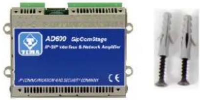
Simply place AD610 on a table or shelf after applying the rubber anti-slip adhesive feet. Alternatively, if desired, it is possible to screw to the bottom of the system the practical accessory adapter for DIN rail using only the 2.5MA cross-head screws and washers supplied. Otherwise fix to the wall using the side fins with fastening eyelets and screw anchors with screws provided. Warning: the side flaps can be opened only once to avoid their weakening.
8.2. Connection
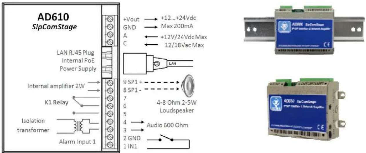
The connection must be carried out by qualified technical personnel, operate without power, strictly follow the specifications of voltage and current levels indicated in the figure.
4-pin removable terminal block
+Vout Terminal block from which it is possible to withdraw unregulated power supply, POSITIVE GND Terminal block from which it is possible to withdraw unregulated power supply, NEGATIVE

At the "+Vout" output there is a +12Vdc voltage when the device is powered via PoE, otherwise, at this output the voltage will be the same as at the terminals A-C. The use of "+Vout" is permitted as long as it is not exceeded a maximum 200mA current consumption and the load has a protection on the input current. Improper use of this output will permanently damage the unit.
A Terminal block to power the system, irrelevant polarity C Terminal block to power the system, irrelevant polarity
RJ45 LAN port
AD610 requires a LAN cable to connect to the network. If the port cable has also PoE, it will not be necessary to supply the module with other power sources (Recommended solution).

Devices powered via PoE (Power over Ethernet) may only be connected with cables coming from inside the building, they are not allowed connections to LAN cables coming from outside the building.
9-pin removable terminal block
| 9 SP1+ | Class-D amplifier output terminal block for connection of an external speaker, positive pole |
| 8 SP1- | Class-D amplifier output terminal block for connection of an external speaker, negative pole |
| 7 | Terminal block of the K1 relay – NC contact, normally closed |
| 6 | Terminal block of the K1 relay - CC contact, central contact (contact load max 30V 1.5A) |
| 5 | Terminal block of the K1 relay - NO contact, normally open |
| 4 | Isolated transformer audio output terminal block to connect to the input of the PA Amplifier |
| 3 | Isolated transformer audio output terminal block to connect to the input of the PA Amplifier |
| 2 GND | Terminal block referred to the negative of the system power supply, for the alarm contact |
| 1 ING1 | Terminal block for the detection of the external alarm contact |

To terminals 1 (INP1) and 2 (GND) must only be connected a relay contact or a button free from any voltage to prevent permanent damage to the device.
Wall installation with dowels
Use the anchors provided and before fixing to the wall fold the flaps with eyelet not used towards the side walls of the device.
Installation on standard DIN rail
Secure the plastic DIN accessory on the back of the device using the 2 flat washers + 2 countersink 2.5x6mm screws supplied and clip onto a standard DIN rail, fold all the flaps with eyelet towards the side walls of the device.
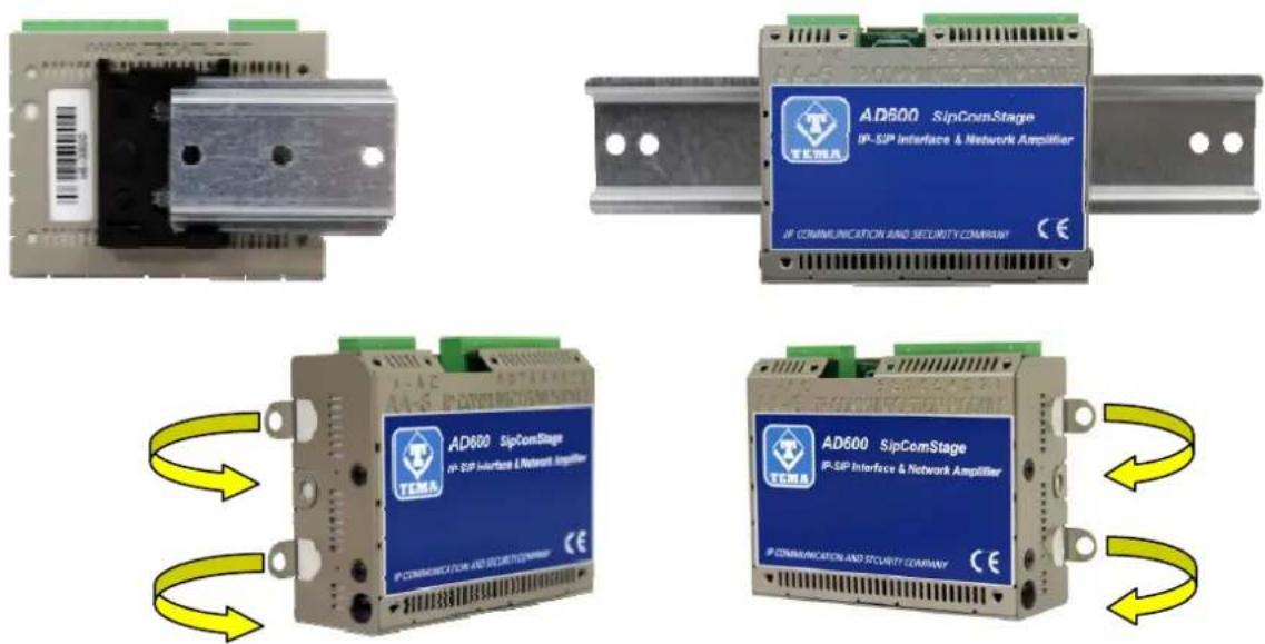
Installation support on table or shelf into Rack cabinet
Apply the non-slip rubber feet provided on the bottom surface of the device, fold all flaps with eyelet towards the side walls of the device.
9. PROGRAMMING
9.1. Preparation for the system parameters programming
Programming is done via the WEB interface. To gain access, simply connect an Ethernet cable from a PC or from a switch to the LAN port of AD610.
The default IP address of AD610 is "192.168.0.10".
Remember that in order to successfully connect to the web interface of AD610, it is necessary that, in the IP addresses configuration of your PC, is present the subnet 192.168.0.x, where "x" is any number between 1 and 254 and different from 10. See below how to configure your PC to reach the correct subnet. The shown procedure applies to Windows® operating systems.
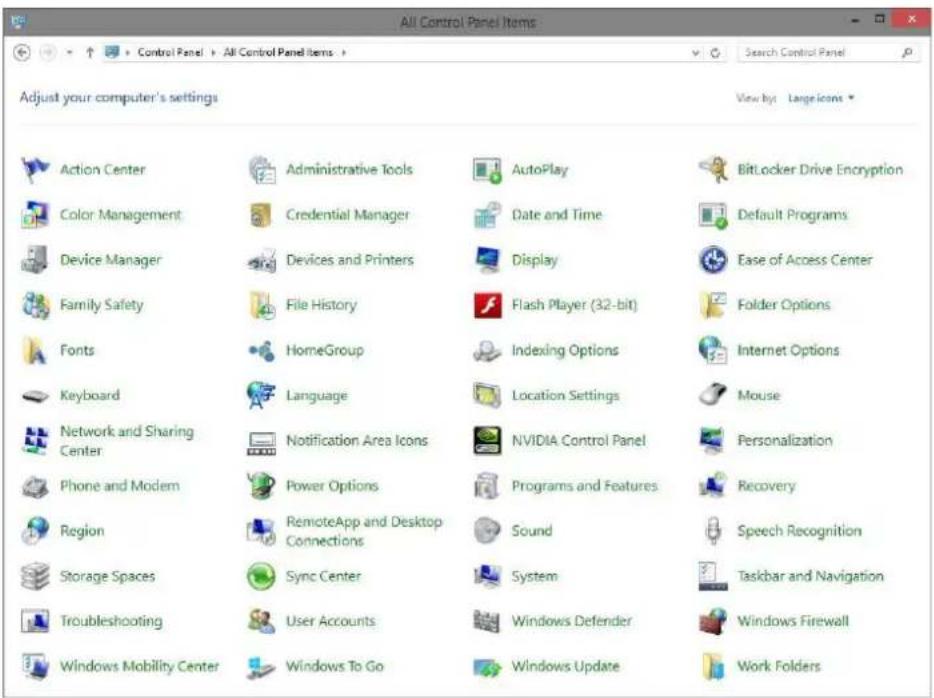
Open the Windows Control Panel and set the field "View by": "Category" "Large Icons" or "Small Icons".
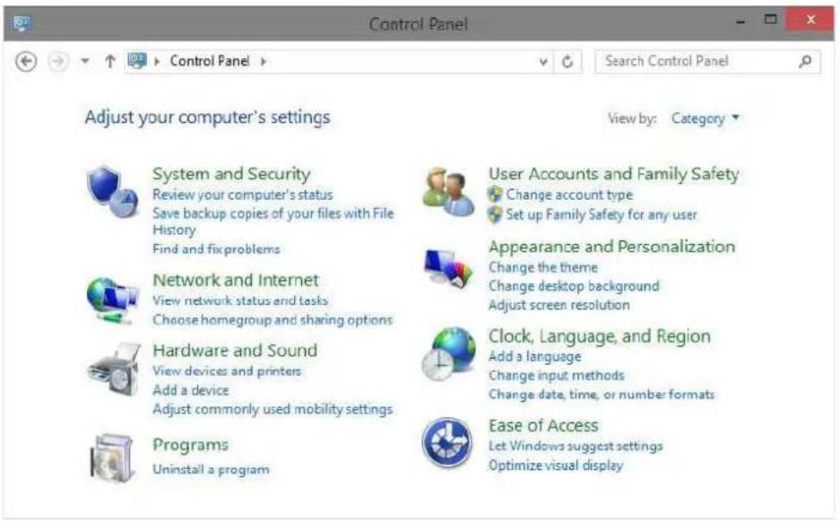
Choose "Network and Sharing Center" as shown in the first figure, detect your LAN connection, choosing the one referring to the network card that you are using to connect with AD610.
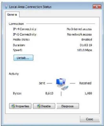
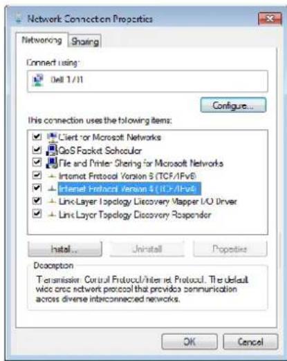
Once the correct connection is identified, click on it and it will appear the window where it is necessary to click on the "Properties" button. It will then open the window where must be selected "Internet Protocol Version 4 (TCP / IPv4)" and then click the Properties button again. See the following figures:
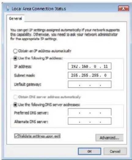
If the PC is already on subnet 192.168.0.x with a mask 255.255.255.0, ignore the following steps. Otherwise, proceed as follows. (The address of the PC configuration should not be 192.168.0.10). Remember the current TCP/IP configuration of your computer for any subsequent restore of the correct parameters. Click "Use the following IP address" and type in the appropriate field the following IP address: 192.168.0.11 (instead of "11" used in the example it is possible to enter any number between 1 and 254, but excluding the 10 which is the default address of the system to be programmed). In the "Subnet Mask" enter the netmask 255.255.255.0. Click OK to confirm the changes. The PC is now ready to configure the door phone. Remember at the end of programming to restore the network configuration of the PC to its original state if necessary.
Once the IP address of your PC is successfully configured, it is possible to reach the Web interface to configure AD610 at the address 192.168.0.10.
9.2. Access to programming
To program the device, it is sufficient to use a standard browser such as Explorer, Firefox, Chrome or others.
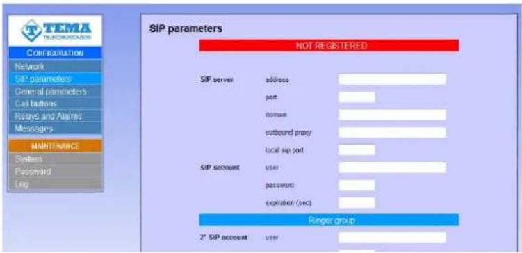
The default address of the device is 192.168.0.10 with a mask of 255.255.255.0, and the user/password with which to connect are master / master. Make sure to have access to this network segment from your computer. Once logged in, it is possible to change the administrative password for the maximum safety of your device.. The use is very simple and intuitive, it is always visible on the left the menu for selecting the functions to be programmed, while on the right is shown the configuration window that is currently active. Any change will be confirmed by pressing the "Apply" or "Save" buttons. Closing the browser or changing the page without selecting those buttons will make lost any change. Any changes do not require restarting the device (except the change of IP address, and the software update).
9.3. Network parameters
On this page it is possible to set the network parameters, such as IP address, netmask, etc.:
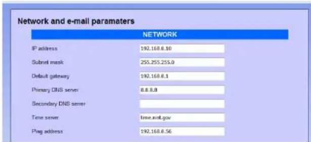
The default IP address of the device is 192.168.0.10 . Gateway and DNS are only needed if you want the device to have the ability to access the Internet (for example to get the current date / time, in the example from the site time.nist.gov).
The changes to the network settings are taken over by the device until the next reboot. Once you have completed the configuration steps so be sure to reboot the system and if necessary, change the network segment of your computer so that it can connect to the new address.
• IP address: specify the IP address you want to assign to AD610.
- Subnet mask: indicate the subnet mask to be assigned to AD610.
- Default gateway: indicate the gateway that can enable AD610 to access to internet.
• Primary and secondary DNS server: indicate the addresses of two DNS servers you want to use to resolve IP addresses.
• Time server: indicate the address of the server you want to use for time synchronization device.
- Test address (ping): if inserted, this address is used by the system to verify the correct operation of the network connection.
9.4. SIP Parameters
Once the network parameters have been set correctly, you must configure the connection with the VoIP SIP PBX:
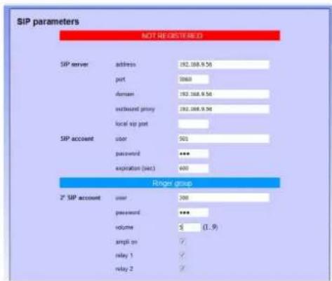
- SIP server address: specify the IP address of the SIP PBX to which AD610 should connect.
- Port: is the port number of the SIP PBX with which AD610 must operate. Generally it is the 5060, but some stations use a different port.
- Domain: enter the domain to which register the system.
- Outbound proxy: some PBXs require that the extension number to call is followed by the proxy address. In most cases this field can be left empty.
- Local SIP port generally the 5060 port is used, but it is possible to specify a different number (i.e. for particular routing tables).
- User/password: credentials for the registration of the extension (which obviously must have been already created on the PBX).
- Expiration: indicates how many seconds the device should check the correct registration of the client.
- 2 ^ND SIP account: this account is used for "Night ringer". It is possible to configure, in the PBX, a ringer group used in night mode, so if the doorphone is put in the same group, it will play the ringer message when receiving an incoming call, without answering.
• Password: the second account registration password.
• Volume: it is possible to set the volume used to reproduce the sound of Night Ringer. It is also the volume used to reproduce the prerecorded announcements.
• Amplifier: no function on AD610, active the amplifier on the Night Ringer service on AD611 / 612. - Relay 1: for the entire duration of the call it is possible to keep the relay1 activated. It can be used for example to turn on a flash, a lamp, etc.
- Relay 2: no function
9.5. General parameters
In this section it is possible to set parameters for general use, such as call duration, audio volume, tones, ringing and so on:
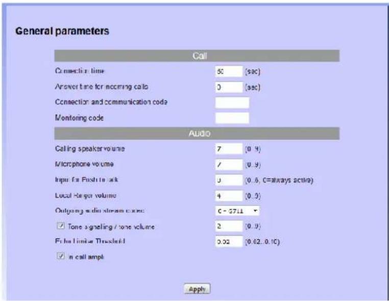
- Connection time: once in connection with the extension, the call is torn down anyway after the set time. Thirty seconds before the end of the call, the system will play a short beep to the user within the company and repeats the message every 5 seconds. At this stage it is possible to type on the phone inside the sequence "#5", which forces the connection time to be reloaded from scratch.
- Answer time for incoming calls: when the system is called, it answers after the set time. If set to 0, responds immediately, if 999 never answers.
- Connection and communication code: when the device receives an incoming call, if this field is programmed, the audio will not be connected until the user will enter the right connection code.
• Monitoring code: this feature is not present in this device, leave the field empty. - Calling speaker volume: sets the sound volume of ads. Possible values range from 0 (very weak) to 9 (very strong).
• Microphone volume: this feature is not present in this device. - Input for Push-to-talk: this feature is not present in this device.
- Ringer volume: sets the volume of the ringer played by the system for incoming calls. Possible values range from 0 (mute ringer) to 9 (very strong).
- Outgoing audio stream codec: in the audio stream mode, it is possible to choose the quality of the transmitted audio, which goes from the G711 (the lowest) to the linear 16 bit 44 kHz (the highest).
- Tone signalling/Tone volume: it is possible to give to the user signalling tones (button pressing, call in progress, end call), sets the volume of any played signaling tones. Possible values range from 0 (very low) to 9 (very strong).
- Echo limiter threshold: this feature is not present in this device.
- In call ampli: indicates whether to activate the audio amplifier during communication. No function on AD610, available on AD611/612.
9.6. Relay and alarm input settings
On this page it is possible to choose the operating mode of the internal relay1 (relay 2 is not present) and the operating mode for external inputs:
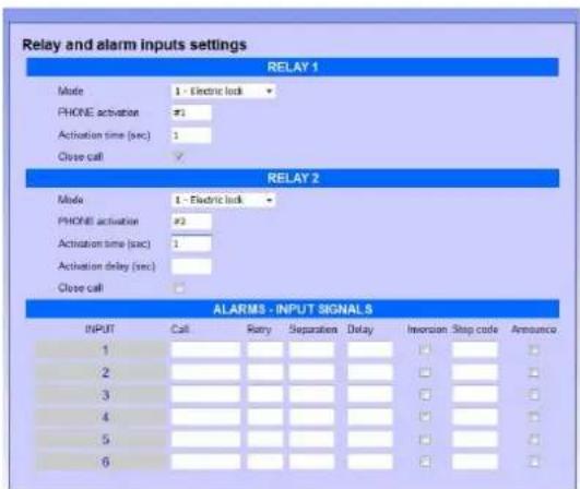
• Mode: sets the function to be associated to the relay. It is possible to choose between:
1 Electric lock: is activated only upon receiving the activation code.
2 In call: is activated when a call is in progress and until the door phone does not come back to idle
3 In call + timer: it activated when a call is in progress and for the activation time
4 Pressure button: you press any key relay is activated for the time set
- PHONE activation: relay activation code to dial from the extension of the PBX (2 characters required), the code that the operator will use to activate the relay
• Activation time: activation time of the relay - Close call: by setting this option, the call is immediately hang up when the relay is activated
- Call.: number or IP address of the phone to contact when the alarm condition is triggered.
• Attempts: number of call attempts (max 999)
• Separation: separation, in seconds, between a call attempt and the other (max 999). - Delay: it is the minimum time, in seconds, before validating the input. It could be useful, for example, to mask an open door switch. Supposing the maximum time of a pedestrian gate is 30 seconds, at the end of this time (if the switch would be still active) an alarm will be send to the reception.
- Inversion: the contact is normally open and the alarm occurs at the closing of the same. Enabling this flag it is possible to instruct the device to behave in the opposite way (the contact is normally closed and the alarm occurs at the opening).
- Stop code: code to dial on the phone calling to accept and acknowledge the alarm (max 3 digits).
- Announce: when activating this input, a prerecorded message will be played on the speaker. See messages management.
In the screenshot are represented up to 6 inputs, but only one is available on this model, other fields have no function. For each input is assigned a different message that will be played during the call. By default a neutral message is played ("Alarm 1", "Alarm 2", etc.) but the text can be customized.
9.7. Call buttons
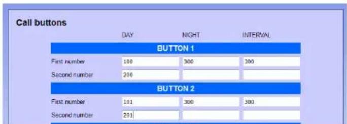
Programming fields not used by the AD610 system.
9.8. Messages management
In this window it is possible to change/listen to the messages for "Calling", "Alarms", "Announcement" and "Ringer". Memory contains a default message for each position, the user can change any of them and the messages format must be WAV PCM 8 kHz, 16 bit, mono.
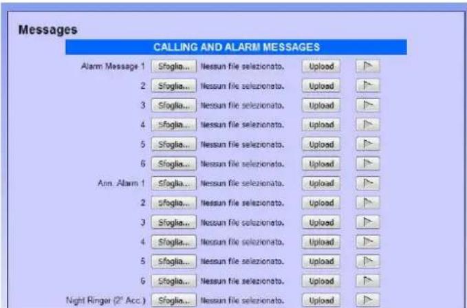
"Alarm messages", one for each input (only the number 1), are reproduced to the called telephone number configured in the alarm input: when the called answers, the message is played continuously, until the user enters the stop code or a timeout expires. "SIP Security Info Call" function. The "PA announcement" messages, even in this case one for each input, are played on local speaker when the check in the alarm programming mask is active. Messages can be played (one of the 6 available optionally) reaching system using a telephone with their activation code. Finally, the "Night ringer" is played on the local speaker when a call is received on the second SIP account, if programmed (par. 9.4).
Activation of one of the 6 "alarm announcements" from phone
It is possible to activate the playing of one of 6 messages even during communication. In the "activation code" field must be programmed the code that is wanted to be used for this function:

In the example the used code is "99". Simply, follow the announcement number after this code (from 1 to 6). When the play starts, the call is hung up (internal extension will be freed). Attention: the message could also be very long, so if you need to interrupt it for some reason, simply call the system, the message will be stopped to make room for new communications.
Multicast audio streaming
By activating this function AD610 will listen to the address / port specified, reproducing audio into a possible digital audio stream received in Multicast in analog mode. This function has a lower priority than the normal telephone operation of the system (outgoing or incoming calls will block or prevent the reproduction of the audio stream).
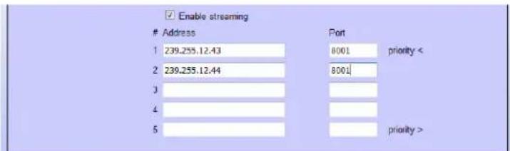
It is possible to configure up to 16 multicast addresses, each one with an higher priority than the previous. In the above example, there are two addresses. The first (.43) could be used to play music at low volume from a PC. The second (.44) could be an announcement from a special programmed phone for Multicast with an higher volume. Generally the music is always on but will stop immediately when an announcement from the phone is received.
9.9. Automatic announcements
It is possible to program the diffusion of announcements at pre-set times, which can take place on the local speaker or streamed to other devices.
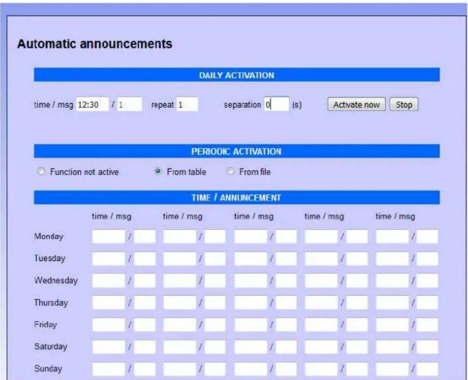
Daily activation:
it is possible to automate the diffusion of a daily announcement (which will take place at the set time) for each day. It will be reproduced for the number of repetitions, with separation between a message and the other given by the number of seconds set. It is also possible to manually activate the message (with the "Activate now" button) or stop playback (with the "Stop" button). If the manual activation mode is only used, it is not necessary to indicate the start time.
The shown message is one of the 6 alarm announcement messages that can be found in the "Message Management" section.
Periodic activation from table:
if you activate this function, it is possible to indicate in the table below, for each day of the week, up to five different times, for each of which it is possible to specify one of the six pre-recorded announcement messages.
Periodic activation from file:
it is possible to upload a text file in "csv" format (easily editable with "Excel") that contains, for each day of the year, up to 5 times in which to make the announcement diffusion. To compile the file simply download the default one already present (and empty), modify it and re-upload it (do not change the written months, are used by the device to index itself in the document):
| A | B | C | D | E | F | G | H | I | J | K | L | M | N | O | |
| 250 | 28 | ||||||||||||||
| 251 | 29 | ||||||||||||||
| 252 | 30 | ||||||||||||||
| 253 | 31 | ||||||||||||||
| 254 set | |||||||||||||||
| 255 | 1 | ||||||||||||||
| 256 | 2 | ||||||||||||||
| 257 | 3 | ||||||||||||||
| 258 | 4 | ||||||||||||||
| 259 | |||||||||||||||
In the example it was indicated that on September 7th (every year) the message 1 should be reproduced at 09.00, message 2 at 12:30 and message 3 at 17:30.
NOTE1:
the playback volume, in the case of diffusion on the local speaker, is the one set as the ringer volume in the "SIP Parameters" programming screen. In the case of streaming playback, the volume is given by the volume of the multicast channel programmed in reception.
NOTE2:
since the device does not have its own internal clock, the automatic diffusion of messages can take place only if it is synchronized with a time server (which can be one into the local network or any other on the internet, see the "Network parameters").
10. MAINTENANCE
10.1. System
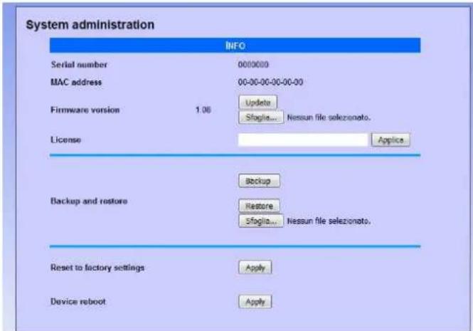
On this page it is possible to check the current firmware version, update software, and backup / restore the system configuration:
• MAC address: is the physical address assigned to the network interface.
- Firmware version: displays the currently installed version of the program. It is possible to upload a different version (possibly provided by the technical support of TEMA) using the Browse/Update. Once you've uploaded the new version, the device must be restarted.
- License: enter in this field the license key to activate any additional services (such as the use of messages over 16 seconds).
- Backup and restore: it is possible to save the current settings to restore them in case of a programming error or device replacement.
- Reset to factory settings: all settings are lost and reset to factory defaults. You are prompted to confirm the operation.
• Device reboot: reboot as if it were taken away and put back power. Useful in case you have not physically present in front of the device and it needs to restart it. You are prompted to confirm the operation.
10.2. Login credentials
By default, the user name and password for access to the configuration are master/master (lowercase). It is not possible to have more than one user (there are not hierarchical levels of programming), but it is possible to change the login credentials. The password must be entered twice for confirmation.
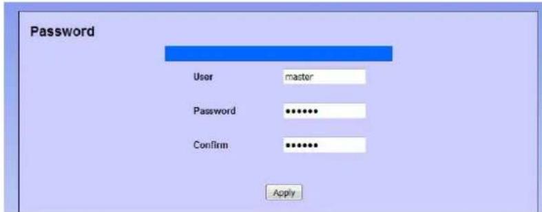

Make a note of the new credentials introduced to then re-enter the system!
10.3. Diagnostic logs
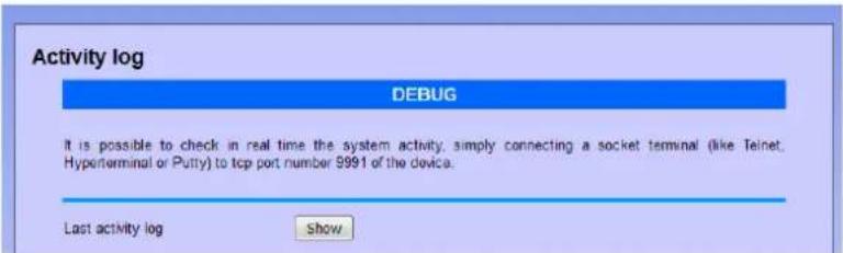
To identify small configuration problems, it is possible to activate a diagnostic summary on the activity of the two VoIP channels of the device. Simply connect via TCP port 9991 with Telnet or a terminal like Hyperterminal. It is also possible to view the history of activities for each module by clicking "Last log". The log is deleted when it exceeds the size of about 2 MB.
11. PRESENTATION AND USE OF THE "AA Video Console" SOFTWARE
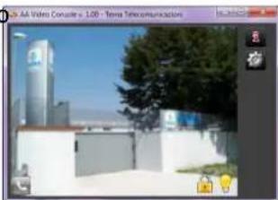
AA-Video Console is an application that comes for free together with the IP audio devices AD600 and IP Video door systems series AA-500 and AA-600, is used to monitor and operate from a single location with 16 audio devices and/or IP videophones. The software is installed on one or more PCs (with no licensing restrictions) with the operating system from Windows XP ^ or later. The program allows to see the area framed by the built-in camera in the IP Intercom devices, to communicate and remotely operate the relay of managed terminals in the network, all from the same program window. The PC where AA-Video Console is installed must have a sound card and equipped with speakers and a microphone. It is possible to display up to 16 scenes/devices simultaneously and operating with a terminal at once chosen from those in the window. To install the program identify in the supplied CD-ROM the file "AAVideoConsole/setup.exe".
natural_image
Exterior view of a modern office building (no signage)11.1. Presentation
This is the main program window. In the case of IP AD630 speakers that are not equipped with the camera, the program shows to the operator the IP speakers available to make announcements from PC. Into the network it is possible to have more than one PC running AA-Video Console program. The operator chooses the area where must perform the announcement without having to remember the device number to call (operating mode which is still available) simply by pressing on the handset symbol present in the box of the desired area.
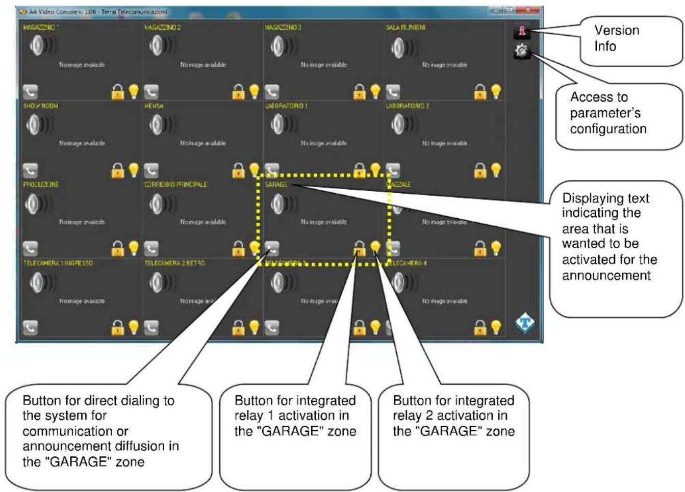
Pressing the handset icon, the program establishes connection with the related terminal and the operator will be able to spread his message by speaking into the microphone connected to the PC.
Changing area is easy, just click on the new desired icon and the connection to the previous announcement is terminated and it is established another to the other area for the new announcement.
11.2. Software configuration for SIP Server mode
It is possible that the company owns or installs between the various IP AD630 audio devices also one or more IP Video Intercoms Tema AA-500 and AA-600 series. These can have the camera that checks and shows in window live images from the framing area. Therefore the PA system can incorporate the control of corporate access points with IP video Intercoms whose video streams are displayed in the windows of the AA-Video Console program.
The audio of the conversation with the devices or the voice communication takes place as a normal VoIP communication between two SIP phones. In this case one of the interlocutors will AD630 (or any IP Videophone), the other is the PC with the "AA Video Console" program.
To make sure that the PC running this program can communicate using AD630 with a user, it is necessary to set the number assigned to "AA Video Console" for that device. By clicking on the configuration parameters button of the program, will appear the window shown below. It is possible to configure up to 16 systems. Select the System tab number to be configured in the AA-Video console and for each one will be the relevant parameters. By activating the checkmark "Active" from the second system, into the main page of the program will adapt in amplitude based on the number of active configured systems.
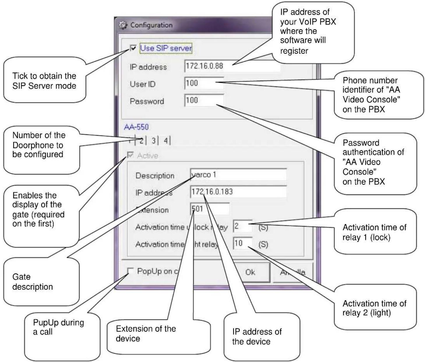
By customizing each description line for the operators will easily and immediately identify the system on the PC screen to be activated to perform the voice announcement from the PC microphone.
11.3. Software configuration for Peer-To-Peer mode
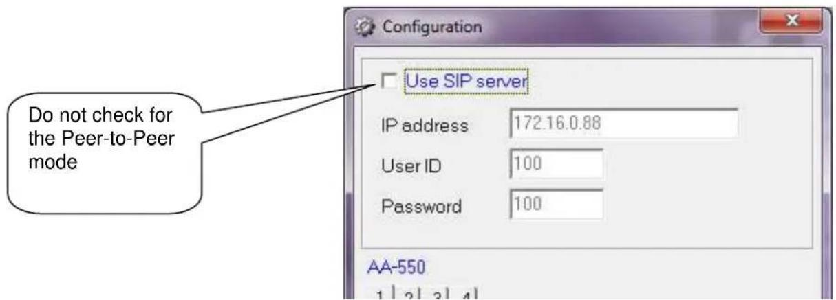
In this configuration mode, the software does not register on a PBX, but makes calls directly to the IP address of the specified device. So the video stream and the audio of the conversation with the device will take place without the intervention of the PBX (the two devices doesn't need to be registered to any existing SIP Server).
In this configuration, one of the interlocutors will be the IP audio terminal or the video intercom, the other is the PC with the "AA Video Console".
To ensure that a user who is in proximity of the terminal (set up with a call button), can "communicate" through the terminal itself with this program on the PC, it is necessary to of course set the IP address of the PC in the terminal parameters (AD630 or AA-500/600). Doing so, after pressing the button, the terminal will forward the call to the IP address of the PC where the "AA Video Console" software is installed.
12. Introduction to AA-Video Console APP version for operating systems iOS
AA-Video Console is a free app that can be installed on any Apple iPhone smartphone.
The program allows to see the area captured by the built-in camera in all the IP VoIP SIP TEMA Audio and Intercoms, to operate the device relays and to speak directly with the visitor. The application can be downloaded from the Apple AppStore, can be easily found typing AAVIDECONSOLE in the search box.
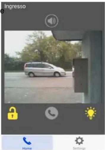
It is possible to configure up to 4 terminals and on your iPhone it will be showed a live image by the selected system camera (to switch from one system to the other just scroll on the display): the video streaming is always displayed, even without communication or calls in progress (continuous video monitor).
Offered services
- Sip calls to the network terminals, launching advertisements on IP SIP speakers
• Operation with both SIP Server and Peer-to-Peer mode - Management of the door relay or step marker light (relay 1 and relay 2) even without necessarily being in communication
- Hands-free audio
• Display of the camera image even when you are not in communication (one Doorphone at a time)
• Up to 4 Doorphones management
12.1. Downloading and installing the app
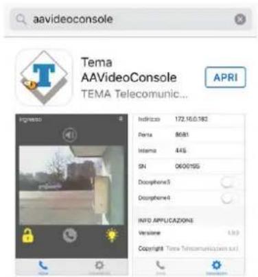
Like all the iPhone Apps, the installation can take place only through the official store. Inside the appstore, simply type AAVIDEOCONSOLE in the search box and confirm the installation:
Configuration
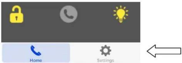
Both the general configuration and the individual Doorphone configuration is done in the "Settings" menu:
You will see the following screen:
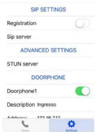
The first part, "SIP SETTINGS", allows to register your device to a PBX or a SIP provider (necessary if you want to reach the Doorphone through its extension number). Marking "Registration" you will have access to the account setup registration (user name, password, etc.). If into the network a SIP PBX is not installed and want to reach the Doorphone simply by its IP address, leave the check unmarked.
In the "ADVANCED SETTINGS" it is possible to configure any STUN Server (external to the private network) that allows the application to reach the Doorphone through a firewall.
NOTE: to access the Doorphone from outside the corporate network (ie from the Internet) it is necessary to program your router / firewall to allow incoming connections to an internal device. For this feature contact your network administrator (each router / firewall has its own programming that it is not possible to generalize in this manual).
Configuring Tema IP SIP terminals
It is possible to control with the application up to 4 systems simultaneously. Also in the settings page is the menu to configure them:
| DOORPHONE | |
| Doorphone1 | |
| Doorphone2 | |
| Doorphone3 | |
| Doorphone4 | |
Activating the slider of each Doorphone (or IP audio system), the fields to be configured will appear:
The description appears in the displayed image and is useful to identify the selected Doorphone from time to time.
In the address field you must enter the IP address of the Doorphone. It is used show the camera or to make a call in Peer-to-Peer.
The port number is used internally by the program for the communications, must be 8081.
The extension number is the number that must be dialed when from the main screen is selected the call key. Obviously it makes sense only in SIP registered to the PBX Server. In Peer-to-Peer mode this field cannot be filled.
| DOORPHONE | |
| Doorphone1 | |
| Description Ingresso | |
| Address | 172.16.7.17 |
| Port | 8081 |
| Extension | 445 |
| SN | 0628057 |
| Doorphone2 | |
| Doorphone3 | |
Finally in the field SN you must enter the serial number of the device. For safety reasons, it is needed to enable the opening keys for relay 1 and relay 2).
12.2. Using the application
Once the application is activated, it is possible to check the registration status in the "Home" screen. If you see an "R" in the upper right it means that the application is registered to the SIP PBX.
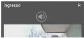
In normal operation, it is displayed the image of the first Doorphone (as mentioned above to switch from one to another simply scroll the screen). The keys below the displayed image will have impact on the selected terminal:
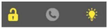
The first button activates the door relay (number 1). The center button makes the call to the Doorphone (or closes if it is in progress). The third button activates the relay normally connected to the light step marker (the number 2).
If the program is put into the background (using the "Home" or "Back" button) it is still active and ready to receive any incoming call (in which case it automatically puts itself in the foreground and is displayed the image of the terminal that has generated the call).
Exit from the App
Proceed as for any other installed iPhone APP.
13. Introduction to AA-Video Console APP version for ANDROID systems
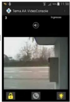
Is a free app that can be installed on any Android ^® smartphone. The program allows to see the area captured by the built-in camera in all the IP VoIP SIP TEMA Doorphones, to operate the device relays and to speak directly with the visitor. The application is on the supplied CD together with the Windows ^® version (in apk format). It is possible to configure an unlimited number of terminals and is presented on your Smartphone a live image at that time by the selected system camera (to switch from one system to just scroll on the display): the video streaming is always displayed, even without communication or calls in progress (continuous video monitor).
Offered services
Are the same as the iOS version (see above).
13.1. Downloading and installing the app
Like all the Android Apps, it is possible to install the app without passing from the store, simply by copying and installing the apk provided in the installation disk. To transfer the file to your device it is possible to follow two paths:
Method 1: send an email to the smartphone with attached aavideconsole.apk file (on the CD). Once the email is opened on your smartphone and select the attachment, the system will ask whether you want install the application (which will happen in a few seconds). Probably the operating system will alert the installation from an unknown source:
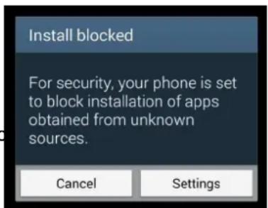
You must select the "Settings" button and allow installation:
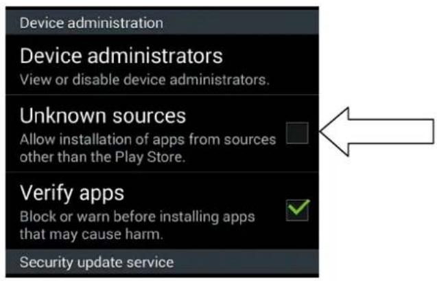
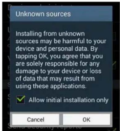
Method 2: copy aavideconsole.apk directly on the device connected to a computer via the USB cable normally supplied with the phone (from "My Computer" the phone is seen like a normal pen drive).
After copying the file you just select it on the phone and confirm the installation (in this case it will also be necessary to authorize the installation from unknown sources).
Configuration
First, from the application menu, the general configuration must be done:
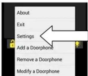
Then click "Settings":
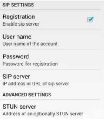
The first part, "SIP SETTINGS", allows to register your device to a PBX or a SIP provider (necessary if you want to reach the device through its extension number). Marking "Registration" you will have access to the account setup registration (user name, password, etc.).
If into the network a SIP PBX is not installed and want to reach the device simply by its IP address, leave the check unmarked.
In the "ADVANCED SETTINGS" it is possible to configure any STUN Server (external to the private network) that allows the application to reach the device through a firewall.
NOTE: to access the device from outside the corporate network (ie from the Internet) it is necessary to program your router / firewall to allow incoming connections to an internal device. For this feature contact your network administrator (each router / firewall has its own programming that it is not possible to generalize in this manual).
Adding Tema IP SIP Terminals
It is possible to add in configuration as many terminals you want. Into the main screen of course it is always presented one at a time.
To switch from one system to the other just slide your finger horizontally on the application display. By choosing "Add a Doorphone" you will see the following screen:
The description appears in the displayed image and is useful to identify selected terminal from time to time.
In the address field you must enter the IP address of the terminal. It is used to show the camera or to make a call in Peer-to-Peer.
The port number is used internally by the program for the communications. If left blank, it will be automatically filled with the default (8081).
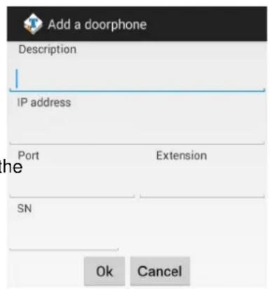
The extension number is the number that must be dialed when from the main screen is selected the call key. Obviously it makes sense only in SIP registered to the PBX Server. In Peer-to-Peer mode this field cannot be filled.
Finally in the field SN you must enter the serial number of the device. For safety reasons, it is needed to enable the opening keys for relay 1 and relay 2).
Edit / delete terminals
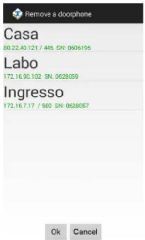
This feature of course allows to change the configuration of a terminal or to delete an inserted one. Simply select from the list the one that you want to edit or delete:
Any changes must be confirmed with the "OK" button. The button "Cancel" or "Back" does not save, useful in case of mistakes.
13.2. Using the application
Once that the application was activated, it is possible to check into the "Info" screen, in addition to the program version, the registration status:
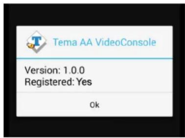
In normal operation, it is displayed the image of the first Doorphone (as mentioned above to switch from one to another simply scroll the screen). The keys below the displayed image will have impact on the selected Doorphone:

natural_image
Three gray icons on black background: lock, telephone handset, and lightbulb (no text or symbols)The first button activates the door relay (number 1). The center button makes the call to the Doorphone (or closes if it is in progress). The third button activates the relay normally connected to the light step marker (the number 2).
If the program is put into the background (using the "Home" or "Back" button) it is still active and ready to receive any incoming call (in which case it automatically puts itself in the foreground and is displayed the image of the Doorphone that has generated the call).
On the taskbar, the program icon will appear, indicating that it is running in the background:
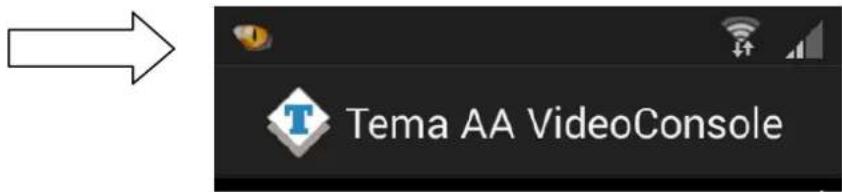
To restore the application in the foreground is therefore sufficient to select it from the toolbar:
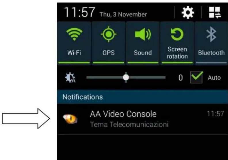
Exit from the App
To end the application, as seen, do not use the "Back" button (like most of the app). To close the program, the "Exit" button must explicitly be selected from the main menu:
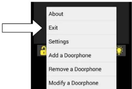
14. APPENDIXES
14.1. Appendix 1: Other examples of Multicast Audio Streaming applications
As described above, in a LAN network the Multicast term refers to the possibility to distribute informations like data, audio or video, to a group of IP terminals of the Ethernet network. For multicast are used Class D addresses that range from 224.x.x.x up to 239.x.x.x. The AD600 systems, in addition to the classic functions previously described in this manual, are able to receive audio in Multicast in the specific IP channel (up to 5 channels) and play it on your speaker. Audio can be generated by a PC software application (for example the free VLC application), from a SIP IP phone or from a TEMA intercom of AA-500 IP series.
It is in fact possible to program each button of the AA-500 IP system for immediately audio sent picked up by his microphone, the received audio stream is played without the intervention of any operator, this function is useful for playing messages and information or emergency announcements (also called "Paging" mode). Any SIP phone that has programmable function keys for Multicast calls can be used.
Audio streaming using multicast is unidirectional, in the sense that the audio stream is sent from the source (such as a phone) to the destination (AD600 Modules) but not vice versa.
The audio stream can be simultaneously sent to multiple terminals that all have the same IP Multicast address, or to distinct terminals (each has its own IP address).
The audio supported by this mode must be in G.711 format (aLaw or Law).
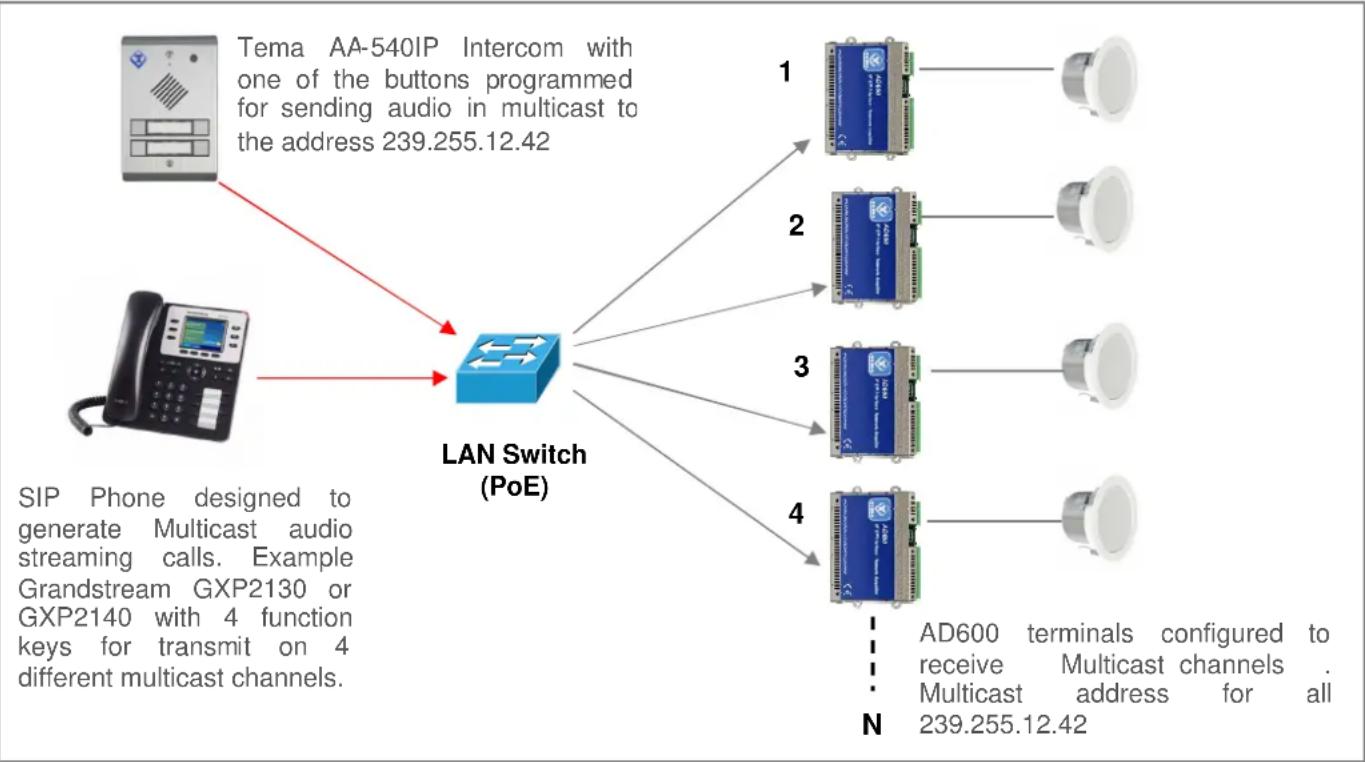
Example of general call in Multicast: The diagram below shows a system where there are 4 devices of the AD600 series connected to the network switch. From a preset telephone it is possible to make a multicast call and launch a voice announcement to the address 239.255.12.42. All the systems are configured with the same multicast address, and then all will reproduce the outgoing audio message.
This function does not affect the normal operation of the AD600 device since the multicast audio is received in a separate channel. At the end of the Multicast announcement, the normal functions are restored.
The use of a PoE (Power over Ethernet) Switch allows to feed the AD600 systems on the same network UTP cable, in this case external power supplies are not needed because the AD600 series systems are compatible with the PoE (Power over Ethernet) standard.
flowchart
graph TD
    A["Tema AA-540IP Intercom with one of the buttons programmed for sending audio in multicast to the address 239.255.12.42"] --> B["LAN Switch (PoE)"]
    C["SIP Phone designed to generate Multicast audio streaming calls. Example Grandstream GXP2130 or GXP2140 with 4 function keys for transmit on 4 different multicast channels."] --> B
    B --> D["1"]
    B --> E["2"]
    B --> F["3"]
    B --> G["4"]
    D --> H["Ad600 terminals configured to receive Multicast channels . Multicast address for all 239.255.12.42"]
    E --> I["Ad600 terminals configured to receive Multicast channels . Multicast address for all 239.255.12.42"]
    F --> J["Ad600 terminals configured to receive Multicast channels . Multicast address for all 239.255.12.42"]
    G --> K["Ad600 terminals configured to receive Multicast channels . Multicast address for all 239.255.12.42"]
Sending Multicast ads to groups (zones) of AD600 terminals
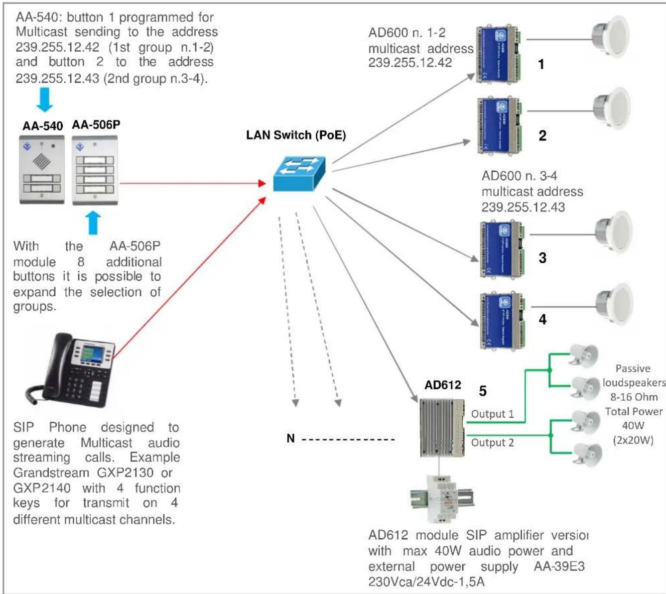
In the plant of the diagram are present 5 AD600 series modules configured into three different groups.
Group 1: AD600 N. 1-2 with IP address 239.255.12.42
Group 2: AD600 N. 3-4 with IP address 239.255.12.43
Group 3: AD612 N.5 with IP address 239.255.12.44
In SIP telephone, suitable for multicast services, are programmed 3 function keys with the IP address of the groups (zones) configured so that each function button can send a multicast announcement on associated group. While the AD600 of the groups 1-2 can drive one 2W speaker, the device N.5 AD612 model integrated a 40W audio amplifier on 2 20W each separate outputs for driving passive speakers or horns in noisy areas or where it is necessaru an high diffusion volume.
It is also possible to use the Tema AA-500 Intercom to generate calls on Multicast channels by appropriately programming the system keys: holding a key the microphone audio is sent to the programmed Multicast IP address. For further needs of groups (zones) it is possible to add a buttons expansion module in the case of AA-540 or a expansion console of the function keys (DDS) in the case of using a SIP telephone.
Each group can have an unlimited number of AD600 devices according to the sound needs in the served area. The number of groups is expandable up to 10. By request the groups can be further expanded.
The 5 multicast channels in AD63x systems have configurable priority levels, so it is possible to reserve the highest priority channel with a dedicated IP address in order to reserve it for the general call on all AD63x or to create combinations of Zones for ads areas.
flowchart
graph TD
    A["AA-540: button 1 programmed for Multicast sending to the address 239.255.12.42 (1st group n.1-2) and button 2 to the address 239.255.12.43 (2nd group n.3-4)."] --> B["AA-540"]
    B --> C["With the AA-506P module 8 additional buttons it is possible to expand the selection of groups."]
    C --> D["LAN Switch (PoE)"]
    D --> E["AD600 n. 1-2 multicast address 239.255.12.42"]
    D --> F["AD600 n. 3-4 multicast address 239.255.12.43"]
    D --> G["AD612"]
    G --> H["AD612 module SIP amplifier version with max 40W audio power and external power supply AA-39E3 230Vca/24Vdc-1.5A"]
    G --> I["Passive loudspeakers 8-16 Ohm Total Power 40W (2x20W)"]
    G --> J["Output 1"]
    G --> K["Output 2"]
    style A fill:#f9f,stroke:#333
    style B fill:#ccf,stroke:#333
    style C fill:#cfc,stroke:#333
    style D fill:#fcf,stroke:#333
    style E fill:#cff,stroke:#333
    style F fill:#ffc,stroke:#333
    style G fill:#cfc,stroke:#333
    style H fill:#fcc,stroke:#333
    style I fill:#fcf,stroke:#333
    style J fill:#cff,stroke:#333
    style K fill:#fcc,stroke:#333
14.2. Appendix 2: Use of the VLC Media Player software as a Multicast Encoder for audio files
With the free VLC software downloadable from http://www.videolan.org/vlc/index.it.html it is possible to turn your Windows PC into an Encoder generator on a multicast IP address that can play a recorded audio file In WAV format 8KHz-16 Bit mono. A file of any duration can be an announcement or a music compilation to be transmitted as a background to all AD600 listening systems on one or more multicast transmission reserved addresses. To do this, follow these steps:
- Download the VLC program and install it on your Windows PC, the folder where the VLC program is installed is located under C:/programmi (x86)/VideoLAN/
- Record a WAV 8KHz-16Bit Mono audio file and copy it into the VideoLAN folder.
- Create a file named "example.bat" as shown in the figure by entering the name of your audio file instead of the one shown in the figure (audiomulti.wav). A copy of the generic "example.bat" file that it is possible to edit is into the supplied CD.
Replace this text with the name of your .WAV audio file recorded at 8KHz-16Bit Mono
Replace this text with the desired multicast IP address, or keep the address shown and configure it on AD600 devices
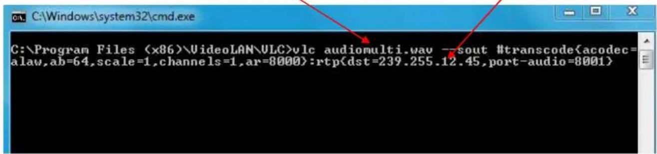
- Replace in the "example.bat" file the shown address (239.255.12.45) with the Multicast address where you want to stream audio, AD600 devices that have to play audio streaming must have set the same receive address on the programming page reserved for multicast. The address shown in the example example file "example.bat" is already a reserved multicast address and can be used in your application.
- Leave unchanged as above all the rest of the string of the file "example.bat".
- When you want to stream over the Multicast channel, double-click on the file "example.bat", the VLC program will automatically opened and the contents of your "xxx.wav" file will be transmitted to all devices AD600 that will play it on the loudspeakers.
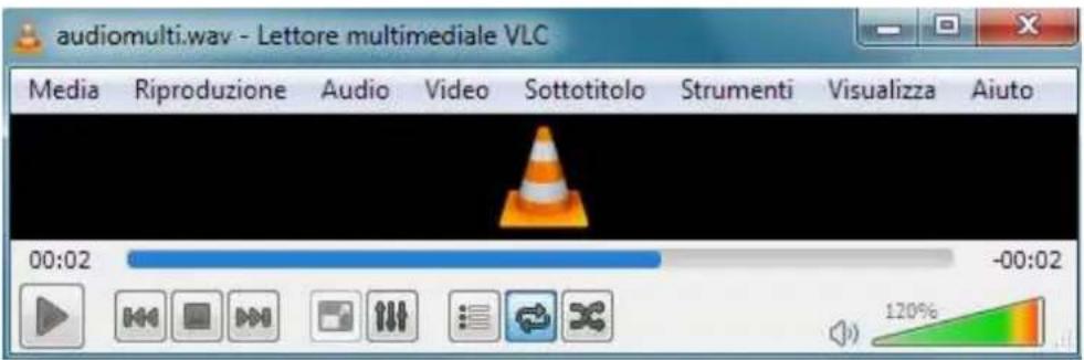
- To pause the streaming, click the Pause button VLC (appears instead of the PLAY button). To end the streaming, close the VLC program.
It is possible to create several "xxx.wav", "xxx1.wav" audio files, which can be linked to as many as "example.bat", "example1.bat" files, and then launch the announcement and/or music from time to time to stream audio to a specific multicast IP address.
For more information on the VLC program, please refer to the manufacturer program guide.
14.3. Appendix 3: Use of the AUDACITY software for audio files recording
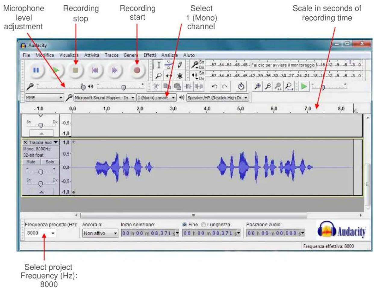
For recording your audio files, it is possible to use one of the free softwares such as AUDACITY downloadable for free from the link http://www.audacityteam.org/ remembering to record and save audio files in .WAV format at 8KHz-16Bit Mono, other audio file formats will not work with the AD600 series devices. Below there are some informations about basic operations. For more information on the AUDACITY program, please refer to the manufacturer program guide.
Proceed as follows to record a message from the built-in microphone or connected to the PC.
- Select the 8,000Hz sampling rate, click Start Recording and start talking.
- To end the recording, click on Stop recording, listen to the recorded audio, and then repeat recording if not optimal. To delete the previous recording, simply select the audio track (crawl from start to finish), press the "Delete" button and repeat the recording. With this procedure it is also possible to delete small parts of silence or sound inside the track.
- To save the recording click on "File", "Export Audio", give a name and select in the "WAV (Microsoft) 16-bit PCM format" drop-down list. The saved file is ready to be used on all devices in the AD600 series or used with the VLC program (see previous appendix) to be sent as Multicast audio streaming.
The AUDACITY software allows a large number of audio signal processing such as: amplification/reduction of audio levels, duplication of track parts, elimination of silences, insertion of DTMF tones or tones, noise reduction, etc. For optimal use please refer to the product manual.
NOTE: TEMA provides you with its own internal recording studio for the creation of professional prompts with multilingual speakers from texts on customer specifications.
14.4. Appendix 4: Cabling of a UTP RJ45 network cable according to the standard EIA568B
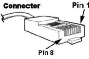 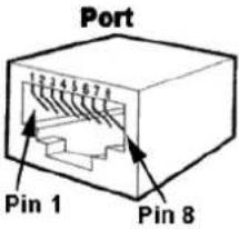 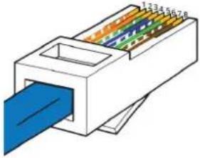  | Pin Signal Connector 1 Connector 2 | |||
| 1 TX+ | White/Orange | White/Orange | ||
| 2 | TX- | Orange | Orange | |
| 3 | RX+ | White/Green | Bianco/Green | |
| 4 | PoE- | Blue | Blue | |
| 5 | PoE- | White/Blue | White/Blue | |
| 6 | RX- | Green | Green | |
| 7 | PoE+ | White/Brown | White/Brown | |
| 8 | PoE+ | Brown | Brown | |
| NB: if the cable colors are different, the right matches must be maintained. | ||||
• Cut the sheath (about one centimeter) to discover the wires.
- To facilitate the process it is possible, by exploiting the elasticity of the sheath, to pull the wires some additional millimeter. (Hold with one hand the wires and with the other pull the smoothing sheath).
• Straighten the wires previously individually pair twisted.
• Compose the color sequence following the pattern.
• Level the length of the cables into place.
- Insert the tightened wires into RJ45 connector holding them between your fingers until they are channeled into the guides inside the connector itself.
- Push well until the wires will touch the bottom of the connector (check in transparency that all the wires are in place).
- Make sure that the sheath has penetrated into the connector for at least 8 mm so that it can also be crimped.
- Place the connector in the crimping tool and tighten all the way. Should be audible a click caused by the outer stop.
- Repeat exactly all the above steps to crimp the cable on the other side.
Notes
Notes
- AD610
- VoIP SIP Multifunction Interface for PA Amplifiers
- Audio Over IP Network Series
- "SlpComStage"
- PRODUCT MANUAL
- DECLARATION OF CONFORMITY CE
- INDEX
- PAGE
- PRESENTATION
- VoIP SIP Amplifiers-Speakers Products and Accessories of the AD600 "SipComStage" series
- AA-39DL
- AA-39D1A
- AA-39P4
- AA-39E3 /-E6V
- FEATURES
- AD610 views and dimensions
- PACKING LIST
- TECHNICAL SPECIFICATIONS
- OPERATION
- Device connection diagrams
- OPERATING MODES
- Calls to AD610
- RELAY function
- Calls generated for acquisition of external contacts for special signalings
- Multicast Audio Streaming
- Example 1
- Example 2
- COMMANDS AND CODES
- INSTALLATION OF THE DEVICE
- Mounting and system positioning
- Connection
- 4-pin removable terminal block
- RJ45 LAN port
- 9-pin removable terminal block
- Wall installation with dowels
- Installation on standard DIN rail
- Installation support on table or shelf into Rack cabinet
- PROGRAMMING
- Preparation for the system parameters programming
- The default IP address of AD610 is "192.168.0.10".
- Access to programming
- Network parameters
- SIP Parameters
- General parameters
- Relay and alarm input settings
- Call buttons
- Messages management
- Activation of one of the 6 "alarm announcements" from phone
- Multicast audio streaming
- Address
- Automatic announcements
- Daily activation:
- Periodic activation from table:
- Periodic activation from file:
- NOTE1:
- NOTE2:
- MAINTENANCE
- System
- Login credentials
- Diagnostic logs
- PRESENTATION AND USE OF THE "AA Video Console" SOFTWARE
- Presentation
- Software configuration for SIP Server mode
- Software configuration for Peer-To-Peer mode
- Introduction to AA-Video Console APP version for operating systems iOS
- Offered services
- Downloading and installing the app
- Configuration
- Configuring Tema IP SIP terminals
- Using the application
- Exit from the App
- Introduction to AA-Video Console APP version for ANDROID systems
- Downloading and installing the app
- Adding Tema IP SIP Terminals
- Edit / delete terminals
- Using the application
- APPENDIXES
- Appendix 1: Other examples of Multicast Audio Streaming applications
- Sending Multicast ads to groups (zones) of AD600 terminals
- Appendix 2: Use of the VLC Media Player software as a Multicast Encoder for audio files
- Appendix 3: Use of the AUDACITY software for audio files recording
- Appendix 4: Cabling of a UTP RJ45 network cable according to the standard EIA568B
Brand : Tema
Model : AD610
Category : Uncategorized