VTM-LCD203P - Monitor Vitek - Free user manual and instructions
Find the device manual for free VTM-LCD203P Vitek in PDF.


| Product Type | LED Monitor |
| Display Size | 20 inches |
| Resolution | 1600 x 900 |
| Brightness | 250 cd/m² |
| Contrast Ratio | 1000:1 |
| Response Time | 5 ms |
| Viewing Angle | 170° horizontal / 160° vertical |
| Connectivity | VGA, DVI-D |
| Power Consumption | 20 W typical |
| Weight | 3.5 kg |
| Dimensions (with stand) | 480 x 360 x 180 mm |
| Stand Features | Tilt adjustment |
| Wall Mount Compatible | VESA 100 x 100 mm |
| Built-in Speakers | 2 x 1 W |
| Color | Black |
| Energy Class | A |
| Package Contents | Monitor, Power Cable, VGA Cable, User Manual |
| Cleaning Instructions | Use a soft, dry cloth. Do not use liquid cleaners. |
| Safety Information | Do not expose to moisture or direct sunlight. Use only provided power adapter. |
| Spare Parts Availability | Contact Vitek customer support for power adapter or stand. |
Frequently Asked Questions - VTM-LCD203P Vitek
User questions about VTM-LCD203P Vitek
0 question about this device. Answer the ones you know or ask your own.
Ask a new question about this device
Download the instructions for your Monitor in PDF format for free! Find your manual VTM-LCD203P - Vitek and take your electronic device back in hand. On this page are published all the documents necessary for the use of your device. VTM-LCD203P by Vitek.
USER MANUAL VTM-LCD203P Vitek
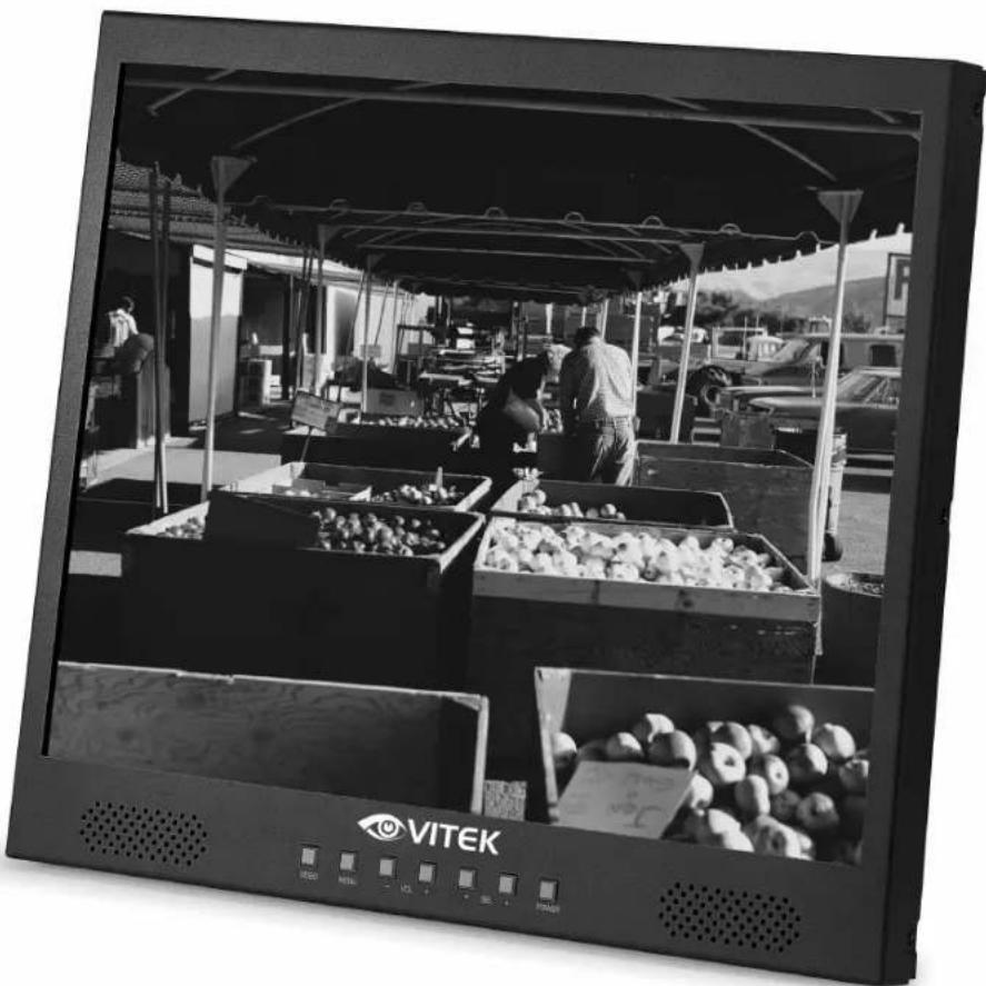
VTM-LCD203P 20.1" Professional LCD Monitor
natural_image
Black-and-white photo of a VITEK TV displaying a market stall with crates of produce under a canopy (no visible text or symbols on the main subject)• 20.1" Color TFT LCD Display
• VGA, BNC Composite, S-Video, and Component Video Inputs
• Stereo RCA & PC Audio Inputs
• Built-In Stereo Speakers
SAFETY INSTRUCTIONS



CAUTION : TO REDUCE THE RISK OF ELECTRIC SHOCK, DO NOT REMOVE COVER, NO USER-SERVICEABLE PARTS INSIDE. REFER SERVICING TO QUALIFIED SERVICE PERSONNEL.
NOTE : This equipment has been tested and found to comply with the limits for a Class B digital device, pursuant to Part 15 of the FCC Rules. These limits are designed to provide reasonable protection against harmful interference in a residential installation. This equipment generates, uses, and can radiate radio frequency energy and, if not installed and used in accordance with the instructions, may cause harmful interference with radio communications. However, there is no guarantee that interference will not occur in a particular installation. If this equipment does cause harmful interference with radio or television reception, which can be determined by turning the equipment off and on, the user should correct the interference by taking one or more of the following actions:
- Re-orient or relocate the receiving antenna.
- Increase the distance between the equipment and receiver.
- Connect the equipment to an outlet on a circuit different from that to which the receiver is connected.
- Consult the dealer or an experienced Radio/TV technician for help.
The user may find the following booklet prepared by the Federal Communications Commission helpful: HOW TO IDENTIFY AND RESOLVE RADIO-TV INTERFERENCE PROBLEMS.
This booklet is available from the US Government Printing Office, Washington, DC 20402, Stock Number 004-000-00345-4
1) Read Instructions
All the safety and operating instructions should be read before the appliance is operated.
2) Retain Instructions
The safety and operating instructions should be retained for future reference.
3) Heed Warnings
All warnings on the product and in the operating instructions should be adhered to.
4) Follow Instructions
All operating and use instructions should be followed.
5) Cleaning
Unplug this product from the wall outlet before cleaning. Do not use liquid cleaners or aerosol cleaners. Use a damp cloth for cleaning the unit.
Exception: A product that is meant for uninterrupted service and that for some specific reason, such as the possibility of the loss of an authorization code for a CATV converter, is not intended to be unplugged by the user for cleaning or any other purpose, may exclude the reference to unplugging the product in the cleaning description.
6) Attachments
Do not use attachments not recommended by the product manufacturer as they may cause hazards.
7) Water and Moisture
Do not use this product near water, for example near a bath tub, wash bowl, kitchen sink, or laundry tube in a wet basement or near a swimming pool and the like.
8) Accessories
Do not place this product on an unstable cart, stand, tripod, bracket or table. The product may fall, causing serious injury to a child or adult, and serious damage to the product. Use only with a cart, stand, tripod, bracket or table recommended by the manufacturer, or sold with the product. Any mounting of the product should follow the manufacturer's instructions, and should use a mounting accessory recommended by the manufacturer.
9) Any product and cart combination should be moved with care. Quick stops, excessive force, and uneven surfaces may cause the product and cart combination to overturn.
10) Ventilation
Openings in the cabinet are provided for ventilation and to ensure reliable operation of the product and to protect it from overheating and these openings must not be blocked or covered. The openings should never be blocked by placing the product on a bed, sofa, rug or other similar surface. This product should not be placed in a built-in installation such as a bookcase or rack unless proper ventilation is provided or the manufacturer's instructions have been adhered to.
SAFETY INSTRUCTIONS
11) Power Sources
This product should be operated only from the type of power resource indicated on the marking label. If you are not sure of the type of power supply to your home, consult your appliance dealer or local power company. For products intended to operate from battery power or other sources, refer to the operating instructions.
12) Grounding or Polarization
This product is equipped with a three-wire grounding-type plug a plug having a third (grounding) pin. This plug will only fit into a grounding-type power outlet. This is a safety feature. If you are unable to insert the plug into the outlet, contact your electrician to replace your obsolete outlet. Do not defeat the safety purpose of the grounding-type plug.
13) Power-Cord Protection
Power-supply cords should be routed so that they are not likely to be walked on or pinched by items placed upon or against them paying particular attention to cords at plugs, convenience receptacles, and the point where they exit from the product.
14) Protective Attachment Plug
The product is equipped with an attachment plug having overload protection. This is a safety feature. See instruction Manual for replacement or resetting of protective device. If replacement of the plug is required, be sure the service technician has used a replacement plug specified by the manufacturer that has the same overload protection as the original plug.
15) Outdoor Antenna Grounding
If an outside antenna or cable system is connected to the product, be sure the antenna or cable system is grounded so as to provide some protection against voltage surges and built-up static charges. Article 810 of the National Electrical Code. ANSI/NFPA 70, provides information with regard to proper grounding of the mast and supporting structure, grounding of the lead-in wire to an antenna discharge unit, size of grounding conductors, location of antenna-discharge unit, connection to grounding electrodes, and requirements for the grounding electrodes.
16) Lightning
For added protection for this product during a lightning storm, or when it is left unattended and unused for long periods of time, unplug the product from the wall outlet and disconnect the antenna or cable system. This will prevent damage to the product due to lightning and power line surges.
17) Power Lines
An outside antenna should not be located in the vicinity of overhead power lines or other electric light or power circuits, or where it can fall into such power lines or circuits. When installing an outside antenna system, extreme care should be taken to keep from touching such power lines or circuits as contact with them may be fatal.
18) Overloading
Do not overload wall outlets, extension cords, or integral convenience receptacles as this can result in a risk of fire or electric shock.
19) Object and Liquid Entry
Never push objects of any kind into this product through openings as they may touch dangerous voltage points or short out parts that could result in a fire or electric shock. Never spill liquid of any kind on the receiver.
20) Servicing
Do not attempt to service this product yourself as opening or removing covers may expose you to dangerous voltage or other hazards. Refer all servicing to qualified service personnel.
21) Damage Requiring Service
Unplug the product from the wall outlet and refer service opening to qualified service personnel under the following conditions:
a) when the power-supply cord or plug is damaged,
b) if liquid has been spilled, or objects have fallen into the product.
c) if the product has been exposed to rain or water.
d) if the product does not operate normally by following the operating instructions. Adjust only the controls that are covered by the operating instructions as an improper adjustment of other controls may result in damage and will often require extensive work by a qualified technician to restore the video product to its normal operation.
e) If the product has been dropped or damaged in any way, and
f) When the product exhibits a distinct change in performance - this indicates a need for service.
22) Replacement Parts
When replacements parts are required, be sure the service technician has used replacements parts specified by the manufacturer or have the same characteristics as the original part. Unauthorized substitutions may results in fire, electric shock or other hazards.
23) Safety Check
Upon completion of any service or repairs to this receiver, ask the service technician to perform safety checks to determine that the product is in proper operating condition.
24) Wall or Ceiling Mounting
The product should be mounted to a wall or ceiling only as recommended by the manufacturer.
25) Heat
The product should be situated away from heat sources such as radiators, heat registers, stoves, or other products (including amplifiers) that produce heat.
TABLEOFCONTENTS
Safety Instructions 2
Table of Contents 4
Parts Description
- Front Panel Controls 5
- Rear Panel Connections 6
Connecting to a Video Source 7
OSD Menus
- OSD Menu Index (Video Mode) 8
- OSD Menu Index (PC Mode) 9
- Picture Menu (Video Mode) 10
- Picture Menu (PC Mode) 11
- Sound Menu (Video & PC Mode) 12
- Geometry Menu (PC Mode) .....13
- Function Menu (PC Mode) ..... 14
VESA Wall Mount / Extension Arm Installation 15
Troubleshooting 16
Specifications 17
Warranty Information 19
FRONT PANEL CONTROLS
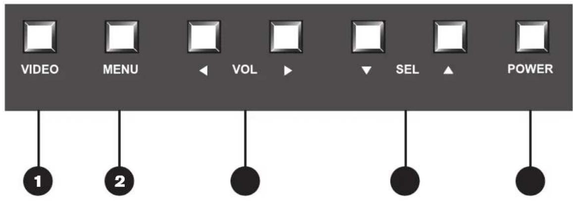
| 1 | VIDEOThe VIDEO button changes the video input source. |
| 2 | MenuThe MENU button turns the On Screen Display (OSD) on/off and is used to enter/exit sub-menus. |
| 3 | VOL (Volume)The VOL button controls the volume of the sound and is used to adjust values within the OSD menus. |
| 4 | SEL (Select)The SEL button navigates through the OSD menus. |
| 5 | POWERThe POWER button turns the monitor on and off. |
REAR PANEL CONNECTIONS
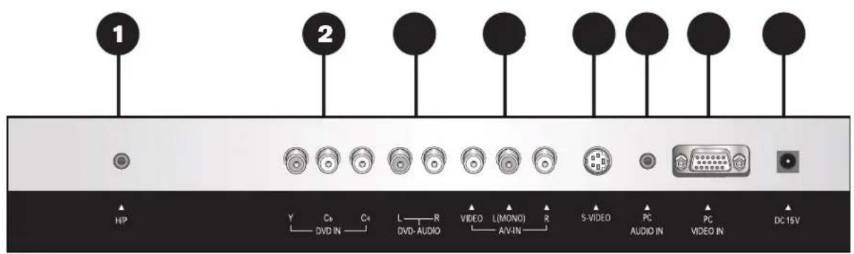
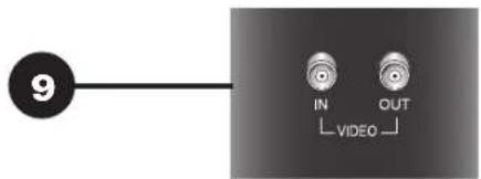
1 HEADPHONE Audio output for use with devices that utilize a 3.5mm interface including: headphones, PC speakers, and computers.
2 DVD IN Analog Y, Pb, Pr component video input.
3 DVD AUDIO Stereo RCA audio input enabled while DVD Input is enabled.
4 A/V IN RCA Video and Stereo RCA audio input. The audio input also accepts a mono signal when connected only to the Left channel. This audio input is also enabled while the S-VIDEO input is selected.
5 S-VIDEO S-Video input for use with devices that utilize a S-Video interface including: S-VHS VCRs and computers.
6 PC AUDIO IN Audio input for use with devices that utilize a 3.5mm interface including: computers and music players.
7 PC VIDEO IN Analog PC 15-pin VGA input.
8 DC 15V Connects the included 15V DC power supply.
9 VIDEO Looping BNC composite video input/output for use with devices that utilize a BNC video connection interface including: analog and digital recorders, multiplexers, quads, and switchers.
CONNECTING TO A VIDEO SOURCE
BNC VIDEO CONNECTION (#9 on Previous Page)
1) Connect a coaxial BNC cable between the BNC VIDEO IN on the monitor and the OUT terminal on the device. An additional device (monitor, recorder, ETC.) can be connected via VIDEO OUT.
2) Connect a set of RCA audio cables between the A/V-IN (L, R) on the monitor and the out terminals on the device. For non-stereo audio sources, connect a single cable from the device to the Left A/V IN Connection.
3) Use the VIDEO button on the front of the monitor to select the VIDEO source.
NOTE: When using the BNC VIDEO IN the RCA/S-Video Connections are not available.
STANDARD / S-VIDEO CONNECTION (#4 & #5 on Previous Page)
1) The A/V video connection can utilize an S-Video or Standard (RCA) video source, but not both simultaneously. Either connect a S-Video cable between the S-Video IN on the monitor and the OUT terminal on the device or connect an RCA cable between the A/V Video IN on the monitor and the OUT terminal on the device.
2) Connect a set of RCA audio cables between the A/V-IN (L, R) on the monitor and the out terminals on the device. For non-stereo audio sources, connect a single cable from the device to the Left A/V IN Connection.
3) Use the VIDEO button on the front of the monitor to select the A/V source.
NOTE: When using the RCA/S-Video Connection the BNC VIDEO IN is not available. The RCA and S-Video inputs can not be used simultaneously.
COMPONENT VIDEO CONNECTION (#2 & #3 on Previous Page)
1) Connect a set of RCA cables between the DVD IN connections on the monitor and the OUT terminals on the device.
2) Connect a set of RCA audio cables between the DVD AUDIO (L, R) on the monitor and the out terminals on the device.
3) Use the VIDEO button on the front of the monitor to select the DVD source.
D-SUB / PC CONNECTION (#6 & #7 on Previous Page)
1) Ensure that the power is turned off on both the monitor and output device (PC, DVR, ETC.)
2) Connect a 15-Pin D-SUB cable between PC VIDEO IN on the monitor and the device.
3) Connect a 3.5mm audio cable between PC AUDIO IN on the monitor and the device.
4) Use the VIDEO button on the front of the monitor to select the PC source.
OSD MENU INDEX (VIDEO MODE)
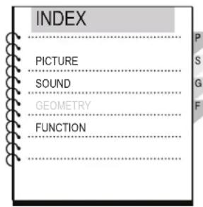
The OSD (On Screen Display) Menu can be accessed by pressing the Menu button on the front of the monitor. Below are the OSD Menus and Sub-Menus while using the Video Inputs. Menus and functions that are unavailable in Video Mode are shaded gray.
Video Mode Top Menu:
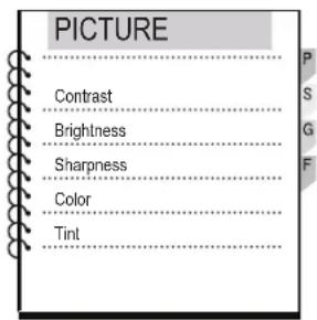
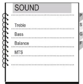
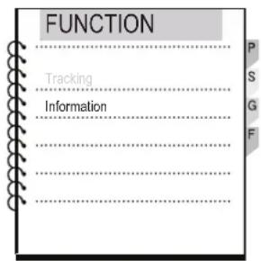
Video Mode Sub-Menus:
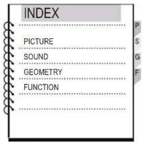
OSD MENU INDEX (PC MODE)
The OSD (On Screen Display) Menu can be accessed by pressing the Menu button on the front of the monitor. Below are the OSD Menus and Sub-Menus while using the PC Input. Menus and functions that are unavailable in PC Mode are shaded gray.
PC Mode Top Menu:
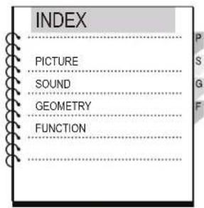
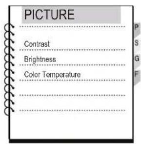
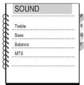
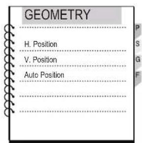
PC Mode Sub-Menus:
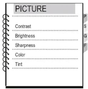
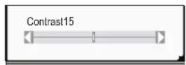
PICTURE MENU ADJUSTMENTS:
1) Press the Menu button on the front of the monitor to access the OSD Index menu.
2) Move the cursor to Picture by pressing SEL (up) or SEL (down).
3) Press VOL (up) or VOL (down) to enter the Picture Sub-Menu.
4) Press SEL (up) or SEL (down) to select one of the following options: Contrast, Brightness, Sharpness, Color, or Tint
5) Press VOL (up) or VOL (down) to display the horizontal slider.
6) Adjustments can be made by pressing the VOL (up) or VOL (down).
7) Press the MENU button to exit the menu.
PICTURE MENU (PC MODE)
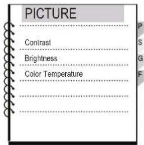
PICTURE MENU ADJUSTMENTS:
1) Press the Menu button on the front of the monitor to access the OSD Index menu.
2) Move the cursor to Picture by pressing SEL (up) or SEL (down).
3) Press VOL (up) or VOL (down) to enter the Picture Sub-Menu.
4) Press SEL (up) or SEL (down) to select one of the following options: Contrast, Brightness, or Color Temperature
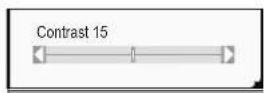
5) Press VOL (up) or VOL (down) to display the horizontal slider.
6) Adjustments can be made by pressing the VOL (up) or VOL (down).
7) Press the MENU button to exit the menu.
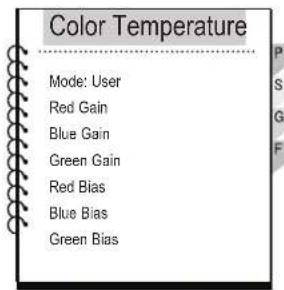
COLOR TEMPERATURE:
The Color Temperature setting offers advanced white balance adjustment:
6500K: Pushes white to the red end of the light spectrum.
STANDARD: Standard white balance.
9300K: Pushes white to the blue end of the light spectrum.
USER: Offers advanced individual Red, Green and Blue Gain & Bias adjustment.
RESET: Resets the color temperature to the factory default..
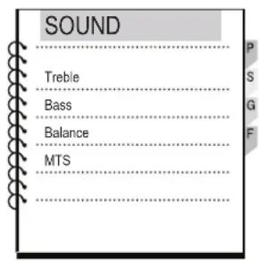
SOUND MENU ADJUSTMENTS:
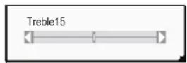
1) Press the Menu button on the front of the monitor to access the OSD Index menu.
2) Move the cursor to Sound by pressing SEL (up) or SEL (down).
3) Press VOL (up) or VOL (down) to enter the Sound Sub-Menu.
4) Press SEL (up) or SEL (down) to select one of the following options: Treble, Bass, Balance, or MTS
5) Press VOL (up) or VOL (down) to display the horizontal slider.
6) Adjustments can be made by pressing the VOL (up) or VOL (down).
7) Press the MENU button to exit the menu.
MTS:
The MTSsetting selects the audio format:
Stereo: When using a stereo audio source (Default).
Mono: When using a mono audio source.
GEOMETRY MENU (PC MODE)
GEOMETRY MENU ADJUSTMENTS:
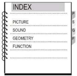
1) Press the Menu button on the front of the monitor to access the OSD Index menu.
2) Move the curser to Geometry by pressing SEL (up) or SEL (down).
3) Press VOL (up) or VOL (down) to enter the Geometry Sub-Menu.
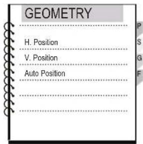
4) Press SEL (up) or SEL (down) to select one of the following options: H. Position, V. Position, or Auto Position
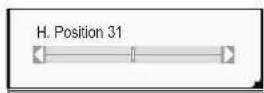
5) Press VOL (up) or VOL (down) to display the horizontal slider.
6) Adjustments can be made by pressing the VOL (up) or VOL (down).
7) Press the MENU button to exit the menu.
GEOMETRY SETTINGS:
H. Position: Adjusts the horizontal position of the screen.
V. Position: Adjusts the vertical position of the screen.
Auto Position: Automatically adjusts the horizontal and vertical position of the screen.
FUNCTION MENU (PC MODE)
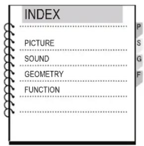
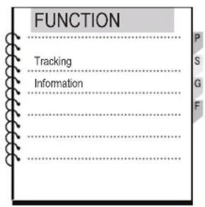
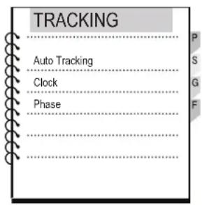
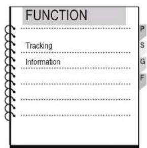
FUNCTION MENU ADJUSTMENTS:
1) Press the Menu button on the front of the monitor to access the OSD Index menu.
2) Move the cursor to Function by pressing SEL (up) or SEL (down).
3) Press VOL (up) or VOL (down) to enter the Function Sub-Menu.
4) Press SEL (up) or SEL (down) to select the Tracking option.
5) Press SEL (up) or SEL (down) to select one of the following options: Auto Tracking, Clock, or Phase
6) Press VOL (up) or VOL (down) to display the horizontal slider.
7) Adjustments can be made by pressing the VOL (up) or VOL (down).
8) Press the MENU button to exit the menu.
TRACKING ADJUSTMENTS
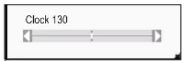
Auto Tracking: Automatically optimizes the Clock and Phase adjustments.
Clock: Adjusts the horizontal size of the screen by increasing or decreasing the amount of pixels.
Phase: Sets the focus of the screen.
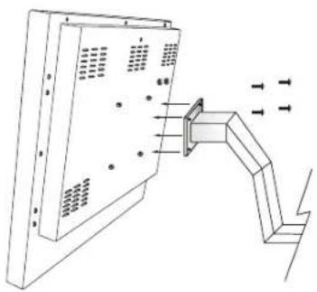
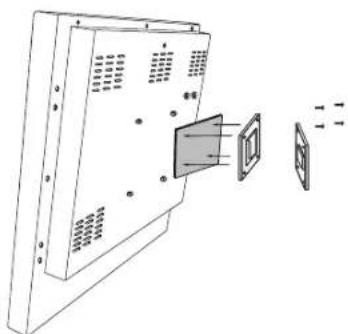
VESA WALL MOUNT / EXTENSION ARM INSTALLATION
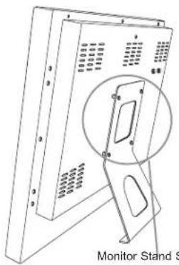
Monitor Stand Screws Extension Arm
natural_image
Diagram of a wall-mounted device with ventilation grilles and a bracket, showing no text or symbolsInstallation
natural_image
Diagram of a computer monitor with an open panel and a close-up view showing internal components (no text or symbols)Wall Mount Installation
REMOVAL / INSTALLATION:
1) Remove the four screws from the monitor stand.
2) Securely fasten the VESA wall mount or VESA extension arm to the back of the monitor.
TROUBLESHOOTING
| What you see... | Suggested Actions |
| Screen is blank and power indicator is off | ● Ensure that the power cord is firmly connected and the LCD monitor is on. |
| “CHECK CABLE OR SIGNAL” message | ● Ensure that the signal cable is firmly connected to the PC or video sources. ● Ensure that the PC or video sources are turned on. |
| “INVALID MODE” message | ● Check the maximum resolution and the frequency of the video adaptor. ● Compare these values with the data in the Display Modes Timing Chart. |
| The image is too light or too dark | ● Adjust the Brightness and Contrast. |
| Horizontal bars appear to flicker, jitter or shimmer on the image | ● Adjust the Clock function. ● Auto Tracking will clear it automatically. |
| Vertical bars appear to flicker, jitter or shimmer on the image. | ● Adjust the Phase function and then adjust the Clock function. ● Auto Tracking will clear it automatically. |
| Screen is blank and power indicator light is steady amber or blinks every 0.5 or 1 seconds | ● The monitor is using its power management system. ● Move the computer’s mouse or press a key on the keyboard |
| Image is not stable and may appear to vibrate | ● Auto tracking will clear it automatically ● Check that the display resolution and frequency from your PC or video board is an available mode for your monitor. On your computer check : Control Panel, Display, Settings |
| Image is not centered on the screen. | ● Auto Position will set the best position automatically ● Adjust the horizontal and vertical position. |
| No sound | ● Ensure that the audio cable is firmly connected to both the audio-in jack on your monitor and the audio-out jack on your sound card. |
| ● Check the volume level | |
| Sound level is too low | ● Check the volume level |
| ● If the volume is still too low after turning the control to its maximum, check the volume control on the computer sound card or software program. | |
| Sound is too high pitched or too low pitched | ● Adjust the Treble and Bass to appropriate level. |
SPECIFICATIONS
DETAILED SPECIFICATIONS
| Panel Type | 20.1" (51cm) TFT Color LCD |
| Display Area | 16.08" x 12.06" (408mm x 306mm) |
| Display Colors | 16.7 Million |
| Pixel Pitch | 0.6375mm x 0.6375mm |
| Recommended Resolution | 640 x 480 @ 85Hz |
| Contrast Ratio | 400:1 |
| Brightness | 400cd/m |
| Viewing Angle | H: 140 degrees V: 120 degrees |
| Scanning Frequency | H: 31-69kHz V: 56-85Hz |
| PC Input | 15 pin D-Sub (Analog RGB) |
| Video Inputs | BNC Composite, S-Video, and Component |
| Audio In/Out | Stereo RCA Inputs x 2 / 1 x 3.5mm Input and Output |
| Certifications | FCC |
| Power Consumption | 65 watts |
| Power Save Mode | 3 watts |
| Screen Control | OSD (On Screen Display Menu) |
| Weight | 18.04 lbs. (8.2kg) |
| Power Supply | 15 VDC |
| Dimensions (w/o Stand) | 17.34" x 14.89" x 2.375" (440mm x 378mm x 60.3mm) |
NOTES
LIMITED LIABILITY WARRANTY
VITEK LCD monitors carry a two (2) year limited warranty FOB VITEK warehouse, except for LCD Panels which carry a one (1) year warranty. VITEK warrants to the purchaser that products manufactured by VITEK are free of any rightful claim of infringement or the like, and when used in the manner intended, will be free of defects in materials and workmanship for a period of two (2) years, or as otherwise stated above, from the date of purchase.
VITEK'S obligation under this warranty shall be limited to the repair, including all necessary parts and cost of labor connected therewith, or at its option, the exchange or a credit issued towards the purchase price of any video equipment which shows evidence of a manufacturing defect within the warranty period. Replacement parts furnished in connection with this warranty shall be warranted for a period equal to the UN-expired portion of the original equipment warranty.
This warranty shall not apply to repairs or replacements necessitated by any cause beyond the control of VITEK, including but not limited to, acts of nature, improper installation, misuse, lack of proper maintenance, accident, voltage fluctuations, and unauthorized repairs or modifications. This warranty becomes VOID in the event serial numbers are altered, defaced, or removed. Shipping charges, if any, must be prepaid. A copy of the bill of sale (or invoice of purchase), together with a complete explanation of the problem must accompany all returns.
A return authorization number or "RA" number must be obtained prior to the return of any item for repair, replacement, or credit. VITEK requires that this "RA" number be printed clearly on the outside of the shipping carton to avoid refusal of said shipment. The Return Authorization number expires after 30 days. Products returned after (30) days are subject to refusal of returned merchandise.

28492 CONSTELLATION ROAD VALENCIA, CA 91355 WWW.VITEKCCTV.COM | 888-VITEK-70
- VTM-LCD203P 20.1" Professional LCD Monitor
- SAFETY INSTRUCTIONS
- CAUTION : TO REDUCE THE RISK OF ELECTRIC SHOCK, DO NOT REMOVE COVER, NO USER-SERVICEABLE PARTS INSIDE. REFER SERVICING TO QUALIFIED SERVICE PERSONNEL.
- 1) Read Instructions
- 2) Retain Instructions
- 3) Heed Warnings
- 4) Follow Instructions
- 5) Cleaning
- 6) Attachments
- 7) Water and Moisture
- 8) Accessories
- 10) Ventilation
- 11) Power Sources
- 12) Grounding or Polarization
- 13) Power-Cord Protection
- 14) Protective Attachment Plug
- 15) Outdoor Antenna Grounding
- 16) Lightning
- 17) Power Lines
- 18) Overloading
- 19) Object and Liquid Entry
- 20) Servicing
- 21) Damage Requiring Service
- 22) Replacement Parts
- 23) Safety Check
- 24) Wall or Ceiling Mounting
- 25) Heat
- TABLEOFCONTENTS
- FRONT PANEL CONTROLS
- REAR PANEL CONNECTIONS
- CONNECTING TO A VIDEO SOURCE
- BNC VIDEO CONNECTION (#9 on Previous Page)
- STANDARD / S-VIDEO CONNECTION (#4 & #5 on Previous Page)
- COMPONENT VIDEO CONNECTION (#2 & #3 on Previous Page)
- D-SUB / PC CONNECTION (#6 & #7 on Previous Page)
- OSD MENU INDEX (VIDEO MODE)
- OSD MENU INDEX (PC MODE)
- PC Mode Top Menu:
- PC Mode Sub-Menus:
- PICTURE MENU ADJUSTMENTS:
- PICTURE MENU (PC MODE)
- COLOR TEMPERATURE:
- SOUND MENU ADJUSTMENTS:
- MTS:
- GEOMETRY MENU (PC MODE)
- GEOMETRY MENU ADJUSTMENTS:
- GEOMETRY SETTINGS:
- FUNCTION MENU (PC MODE)
- FUNCTION MENU ADJUSTMENTS:
- TRACKING ADJUSTMENTS
- VESA WALL MOUNT / EXTENSION ARM INSTALLATION
- REMOVAL / INSTALLATION:
- TROUBLESHOOTING
- SPECIFICATIONS
- NOTES
- LIMITED LIABILITY WARRANTY
Brand : Vitek
Model : VTM-LCD203P
Category : Monitor