
AC3060S - Compressor AEG - Free user manual and instructions
Find the device manual for free AC3060S AEG in PDF.


| Product Type | Silent Air Compressor |
| Rated Motor Power | 2200 W |
| Rated Current | 9.5 A |
| Input Voltage | 220-240 V AC, 50 Hz |
| Air Tank Capacity | 60 L |
| Maximum Air Pressure | 10 bar (145 psi) |
| Working Pressure Range | 7-10 bar (101-145 psi) |
| Free Air Delivery | 240 L/min |
| Maximum Air Delivery | 369 L/min at 0 bar |
| Air Outlets | 2 pcs, 6.35 mm (1/4") NITTO style |
| Weight | 73 kg |
| Power Cord Length | 2 m |
| Sound Pressure Level | 71.89 dB(A) |
| Sound Power Level | 85.78 dB(A) |
| Operating Temperature | 0-45 °C |
| Air Filter Part Number | 039871001022 |
| Wheel Size | 10 inch |
| Tank Drain Valve | Yes, daily draining recommended |
| Safety Valve | Automatic pressure relief |
| Required Assembly | Front handle, feet, wheels, air filters |
| Maintenance Frequency | Check air filters monthly |
| Certifications | RCM, Indoor use only |
Frequently Asked Questions - AC3060S AEG
User questions about AC3060S AEG
0 question about this device. Answer the ones you know or ask your own.
Ask a new question about this device
Download the instructions for your Compressor in PDF format for free! Find your manual AC3060S - AEG and take your electronic device back in hand. On this page are published all the documents necessary for the use of your device. AC3060S by AEG.
USER MANUAL AC3060S AEG
Original instructions
Important!
It is essential that you read the instructions in this manual before assembling, operating and maintaining the product.
Subject to technical modifications.
Fig. 1
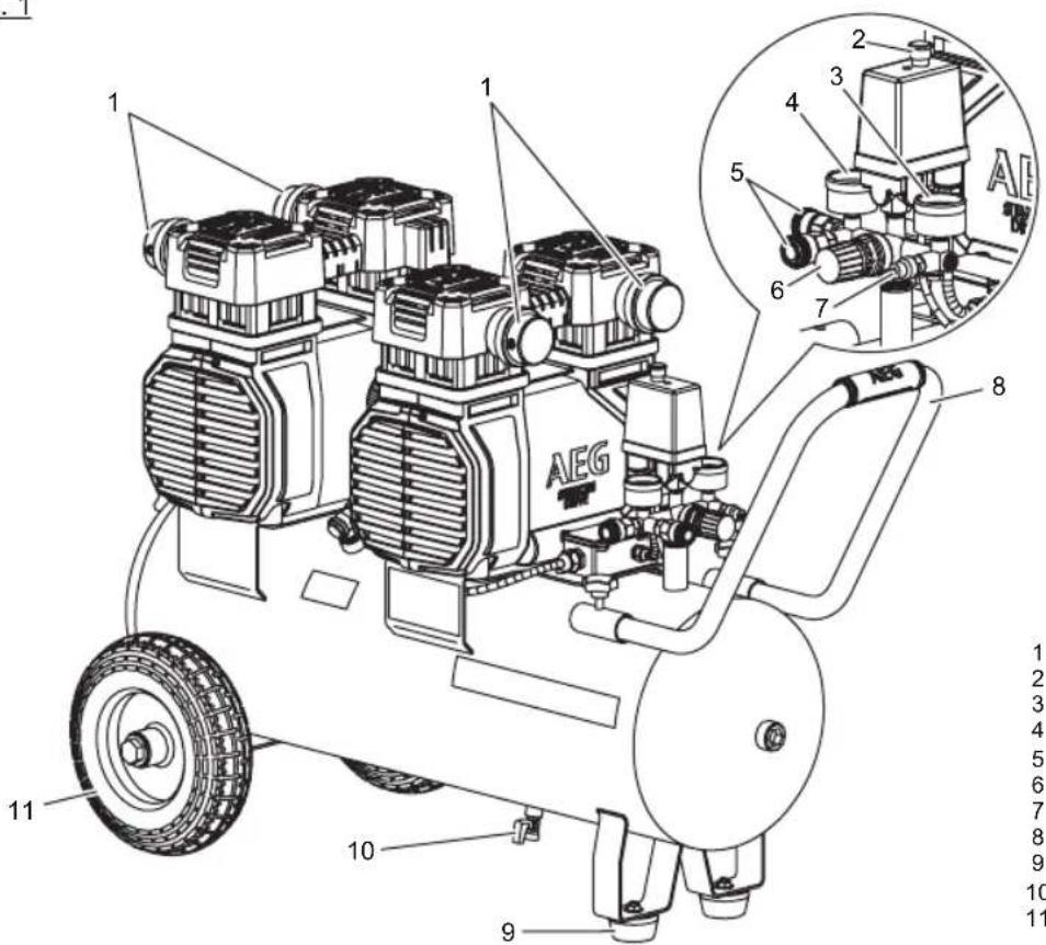
1 - Air filter assembly x4
2 - On/off switch
3 - Tank pressure gauge
4 - Regulator pressure gauge
5 - Quick connect coupler
6 - Pressure regulator knob
7 - Pressure relief valve
8 - Front handle
9 - Rubber foot x2
10 - Drain valve
11 - Wheel x2
Fig. 2
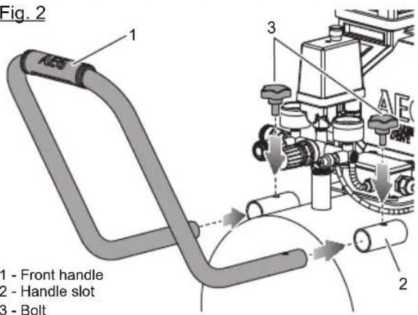
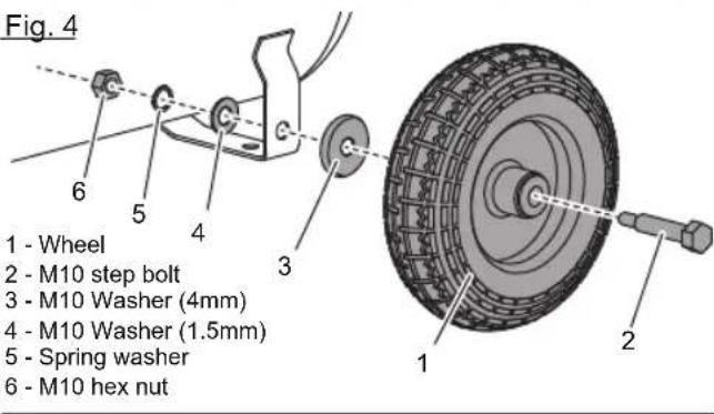
Fig. 3
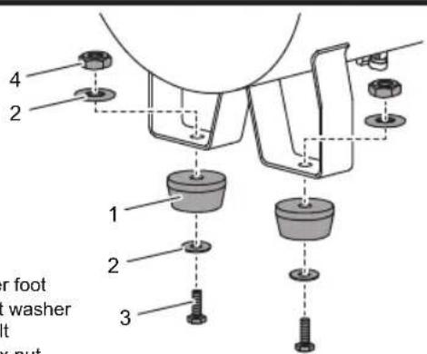
Fig. 5
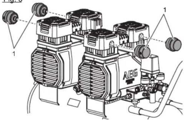
1 - Air filter assembly
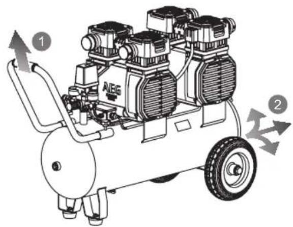
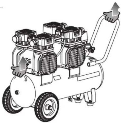
Fig. 6a Fig. 6b
natural_image
Illustration of an air compressor with four motors and a handle, showing mechanical components and directional arrows (no text or symbols)Fig. 7
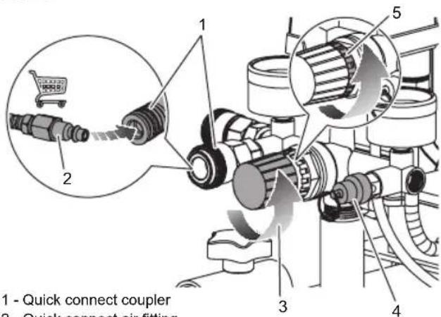
1 - Quick connect coupler
2 - Quick connect air fitting
3 - To close (counterclockwise)
4 - Pressure relief valve
5 - Pressure regulator locking ring
Fig. 8
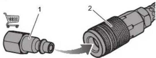
1 - Quick connect air fitting
2 - Quick coupler
Fig. 9
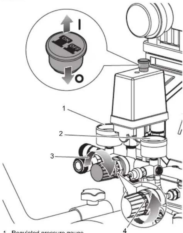
1 - Regulated pressure gauge
2 - Tank pressuse gauge
3 - To open (clockwise)
4 - Pressure regulator locking ring
Fig. 10 Fig. 11
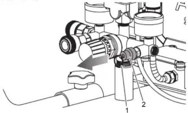
1 - Ring
2 - Pressure relief valve
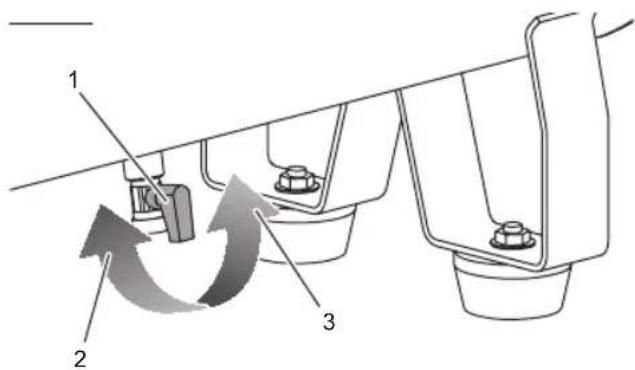
1 - Drain valve
2 - To close
3 - To open
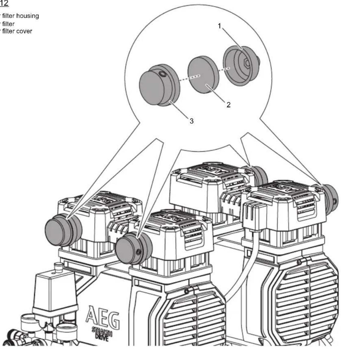
Fig. 12
1 - Air filter housing
2 - Air filter
3 - Air filter cover
TECHNICAL DATA
SILENT AIR COMPRESSOR
AC3060S
| Rated motor power 2200 W | |
| Rated current 9.5 A | |
| Air outlets 2 pcs, 6.35mm (1/4") NITTO style connector/ | |
| coupler (suitable for NITTO fitments) | |
| Quick connector fitting size 6.35 mm (1/4") BSP thread | |
| Weight 73 kg | |
| Input 220 - 240 V AC, 50 Hz | |
| Power cord length | 2 m |
| Air tank capacity | 60 L |
| Free air delivery | 240 L/min |
| Maximum air delivery | 369 L/min at 0 bar tank pressure |
| Maximum air pressure | 10 bar (145 psi) |
| Working pressure range | 7 - 10 bar (101 - 145 psi) |
| Pressure gauge | 2 pcs, 41 mm diameter |
| Maximum rotational shaft speed | 1450 min-1 |
| Short-circuit rating | 3 kA |
| Operating temperature | 0 - 45°C |
| Hazard level | D |
| Plant design registration number | V1900086 |
| Measured sound pressure level (the reference number of the noise test code: EN ISO 2151:2008) | L_pA = 71.89 dB(A), K_pA = 3 dB |
| Measured sound power level (the reference number of the noise test code: EN ISO 2151:2008) | L_wA = 85.78 dB(A), K_wA = 3 dB |
REPLACEMENT PARTS
Air filter
039871001022
WARNING!
Read all safety warnings and all instructions. Failure to follow the warnings and instructions may result in electric shock, fire and/or serious injury.
Save all warnings and instructions for future reference.
GENERAL SAFETY WARNINGS
WARNING
When using electric tools, basic safety precautions should always be followed to reduce the risk of fire, electric shock and personal injury. Read all these instructions before attempting to operate this product and save these instructions.
Read all instructions.
Know your power tool. Read the operator's manual carefully. Learn the applications and limitations as well as the specific potential hazards related to this tool.
WORK AREA SAFETY
- Keep work area clean. Cluttered areas and benches invite accidents. Do not leave tools or pieces of wood on the tool while it is in operation.
■ Do not use in dangerous environments. Do not use power tools in damp or wet locations or expose to rain. Keep the work area well lit. - Keep children and visitors away. All visitors should wear safety glasses and be kept a safe distance from work area. Do not let visitors contact tool or extension cord while operating.
■ Never use in an explosive atmosphere. Normal sparking of the motor could ignite fumes.
ELECTRICAL SAFETY
■ Guard against electrical shock by preventing body contact with grounded surfaces, e.g., pipes, radiators, ranges, refrigerator enclosures.
■ Do not abuse cord. Never carry tool by the cord or yank it to disconnect from receptacle. Keep cord from heat, oil, and sharp edges.
■ Should any electrical component of the tool fail to perform properly, shut off the power switch, remove the plug from the power source and replace before resuming operation.
■ Do not expose power tools to rain or wet conditions. Water entering a power tool will increase the risk of electric shock.
PERSONAL SAFETY
■ Stay alert and exercise control. Watch what you are doing and use common sense. Do not operate tool when you are tired. Do not rush.
■ Dress properly. Do not wear loose clothing, neckties, or jewellery that can get caught and draw you into moving parts. Rubber gloves and nonskid footwear are recommended when working outdoors. Also wear protective hair covering to contain long hair.
■ Always wear safety glasses with side shields. Everyday eyeglasses have only impact-resistant lenses; they are not safety glasses.
■ Protect your lungs. Wear a face or dust mask if the operation is dusty.
■ Protect your hearing. Wear hearing protection during extended periods of operation.
■ Do not overreach. Keep proper footing and balance at all times.
■ Remove adjusting keys and wrenches. Form habit of checking to see that keys and adjusting wrenches are removed from tool before turning it on.
AIR COMPRESSOR USE AND CARE
■ Do not exceed the pressure rating of any component in the system.
■ Protect material lines and air lines from damage or puncture. Keep hose and power cord away from sharp objects, chemical spills, oil, solvents, and wet floors.
- Check hoses for weak or worn condition before each use, making certain all connections are secure. Do not use if defect is found. Purchase a new hose or notify an authorised service centre for examination or repair.
■ Release all pressures within the system slowly. Dust and debris may be harmful.
■ Store idle air compressors out of the reach of children and other untrained persons. Air compressors are dangerous in the hands of untrained users.
■ Maintain air compressors with care. Follow maintenance instructions. Properly maintained products are easier to control.
- Check for misalignment or binding of moving parts, breakage of parts, and any other condition that may affect the product's operation. If damaged, have the air compressor serviced before using. Many accidents are caused by poorly maintained products.
- Keep the exterior of the air compressor dry, clean, and free from oil and grease. Always use a clean cloth when cleaning. Never use brake fluids, gasoline, petroleum-based products, or any strong solvents to clean the unit. Following this rule will reduce the risk of deterioration of the enclosure plastic.
SERVICE
■ When servicing use only identical replacement parts. Use of any other parts may create a hazard or cause product damage.
Save these instructions. Refer to them frequently and use them to instruct other users. If you loan someone this tool, loan them these instructions also.
AIR COMPRESSOR SAFETY WARNINGS
- Know your air compressor. Read operator's manual carefully. Learn its applications and limitations, as well as the specific potential hazards related to this product. Following this rule will reduce the risk of electric shock, fire, or serious injury.
- Drain tank of moisture after each day's use. If unit will not be used for a while, it is best to leave drain valve open until such time as it is to be used. This will allow moisture to completely drain out and help prevent corrosion on the inside of tank.
Risk of fire or explosion. Do not spray flammable liquid in a confined area. Spray area must be well ventilated. Do not smoke while spraying or spray where spark or flame is present. Keep compressors as far from the spraying area as possible, at least 10 m (33 feet) from the spraying area and all explosive vapours.
■ Risk of bursting. Do not adjust regulator to result in output pressure greater than marked maximum pressure of attachment. Do not use at pressure greater than 10 bar.
■ To reduce the risk of electric shock, do not expose to rain. Store indoors.
■ Inspect tank yearly for rust, pin holes, or other imperfections that could cause it to become unsafe.
■ Never weld or drill holes in the air tank.
■ Never use the air compressor with the guard removed.
■ Make sure the hose is free of obstructions or snags. Entangled or snarled hoses can cause loss of balance or footing and may become damaged.
■ Use the air compressor only for its intended use. Do not alter or modify the unit from the original design or function.
■ Always be aware that misuse and improper handling of this product can cause injury to yourself and others.
■ Never leave a tool unattended with the air hose attached.
■ Never point any air tool toward yourself or others.
■ Do not operate this air compressor if it does not contain a legible warning label.
■ Do not continue to use a tool or hose that leaks air or does not function properly.
■ Always disconnect the air supply and power supply before making adjustments, servicing a product, or when a product is not in use.
■ Do not attempt to pull or carry the air compressor by the hose.
- Your tool may require more air consumption than this air compressor is capable of providing.
■ Always follow all safety rules recommended by the manufacturer of your air tool, in addition to all safety rules for the air compressor. Following this rule will reduce the risk of serious personal injury.
■ Never direct a jet of compressed air toward people or animals. Take care not to blow dust and dirt towards yourself or others. Following this rule will reduce the risk of serious injury.
■ Do not use this air compressor to spray chemicals. Your lungs can be damaged by inhaling toxic fumes. A respirator may be necessary in dusty environments or when spraying paint. Do not carry while painting.
■ Inspect product cords and hoses periodically and, if damaged, have them repaired at your nearest authorised service centre. Constantly stay aware of cord location. Following this rule will reduce the risk of electric shock or fire.
■ Never use an electrical adaptor with this grounded plug.
- Check for damaged parts. Before further use of the air compressor or air tool, a guard or other part that is damaged should be carefully checked to determine that it will operate properly and perform its intended function. Check for alignment of moving parts, binding of moving parts, breakage of parts, mounting, and any other conditions that may affect its operation. A guard or other part that is damaged should be properly repaired or replaced by an authorised service centre. Following this rule will reduce the risk of serious injury.
■ Never store a tool with an air line connected. Storing the tool while connected to an air supply can result in unexpected operation, firing or movement and possible serious personal injury.
■ Protect your lungs. Wear a face or dust mask if the operation is dusty. Following this rule will reduce the risk of serious personal injury.
■ If the power supply cord is damaged, it must be replaced only by the manufacturer or by an authorised service centre to avoid risk.
■ Save these instructions. Refer to them frequently and use them to instruct others who may use this product. If you loan someone this product, loan them these instructions also.
■ The machine shall be connected to a circuit protection device (fuse or circuit breaker).
■ Connect the mains lead to a standard electrical supply which has protection devices of over current (10A, 220-240V, 50Hz).
■ Operate the machine from the front of the control panel.
■ When the machine is in operation, many parts of machine may cause a high temperature. Use necessary personal protection equipment such as gloves to avoid injuries resulting from a high temperature.
■ When using the product with an extension cord, use a 3 x 1.5mm heavy duty extension cord only.
This machine is not intended for use by persons (including children) with reduced physical, sensory or mental capabilities, or lack of experience and knowledge. Children should be supervised to ensure that they do not play with the machine.
RESIDUAL RISKS
Even when the product is used as prescribed, it is still impossible
to completely eliminate certain residual risk factors. The following hazards may arise and the operator should pay special attention to avoid the following:
■ Use the product only for its intended use. Do not alter or modify the product from the original design or function.
■ Always be aware that misuse and improper handling of the product can cause injury to yourself and others.
■ Never leave an air compressor unattended with the hose attached to a tool.
■ Do not continue to use an air compressor or hose which leaks air or does not function properly.
Risk of bursting
- Do not adjust regulator to result in output pressure greater than marked maximum pressure of attachment.
- Heat and high temperature are generated while motor and cylinder are running. Touching exposed metal can result in serious burns.
- Always keep the air compressor away from the working zones.
■ Injury casued by noise
— Wear ear protection.
- The gas from air compressor can propel dirt, chips, loose particles and small objects at high speed. This may result in objects being thrown into eyes or other possible serious injury.
- Always wear proper personal protective equipment when operating different tools.
SPECIFIED CONDITIONS OF USE
This compressor is designed to supply pressurised air only. It must not be used to compress any other gas. It is designed to operate air powered tools. The compressor should be operated indoors only.
ASSEMBLY
UNPACKING
This product requires assembly. Carefully remove the product and any accessories from the box.
WARNING
Do not use this product if any parts on the packing list are already assembled to your product when you unpack it. Parts on this list are not assembled to the product by the manufacturer and require customer installation. Use of a product that may have been improperly assembled could result in serious personal injury. Inspect the product carefully to make sure no breakage or damage occurred during shipping.
Do not discard the packing material until you have carefully inspected and satisfactorily operated the product.
WARNING
If any parts are damaged or missing do not operate this product until the parts are replaced. Use of this product with damaged or missing parts could result in serious personal injury.
WARNING
Do not attempt to modify this product or create accessories not recommended for use with this product. Any such alteration or modification is misuse and could result in a hazardous condition leading to possible serious personal injury.
WARNING
Do not connect to power supply until assembly is complete. Failure to comply could result in accidental starting and possible serious personal injury.
Packing list
— Air compressor
- Front handle
— Air filter x 4
— Wheel x 2
- Rubber foot x 2
- M10 Step bolt x 2
- M8 bolt x 2
— Front handle locking bolt x 2
- M10 hex nut x 2
- M8 hex nut x 2
- M10 x 4 mm flat washer x 2
- M10 x 1.5 mm flat washer x 2
- M8 flat washer x 4
- M10 spring washer x 2
- Operator's manual
INSTALLING FRONT HANDLE
See figure 2.
- Insert both ends of the front handle in handle slots.
- Align the holes on the front handle and handle slots. Secure both ends with locking bolts and hand tighten.
INSTALLING FEET
See figure 3.
- Place a rubber foot under the left supporting frame at the front. Align the screw holes.
- Insert an M8 bolt and M8 flat washer in the holes in the rubber foot and the supporting frame from the bottom.
- Insert an M8 flat washer at the other end.
- Secure the rubber foot with an M8 hex nut.
- Repeat the above steps to install the other foot on the right.
- Ensure the compressor is stable by gently applying lateral force on it.
INSTALLING WHEELS
See figure 4.
- Insert an M10 step bolt in the centre hole of the wheel.
- Insert the threaded section of the step bolt in the hole in the rear brace on the left. Place a 4 mm washer between the wheels and frame, and place a 1.5 mm washer on the inside of the frame.
- Insert a spring washer.
- Secure the step bolt with an M10 hex nut.
- Repeat the above steps to install the other wheel on the right.
- Ensure the compressor is stable by gently applying lateral force on it.
INSTALLING AIR FILTERS
See figure 5.
Attach one air filter to each of the cylinder covers. Screw in a clockwise direction to fasten securely.
OPERATION
DANGER
Do not disassemble check valve, tank drain valves or safety relief valve with air in tank — bleed tank.
WARNING
Always wear eye protection with side shields. Failure to do so could result in objects being thrown into your eyes resulting in possible serious injury.
WARNING
Do not attach any tools to the open end of the hose until start-up has been completed.
CAUTION
Do not use in an environment that is dusty or otherwise contaminated. Using the air compressor in this type of environment may cause damage to the unit.
TRANSPORTING THE AIR COMPRESSOR
See figure 6a.
The air compressor should be moved as instructed. This will help you avoid damaging the wheel or the air compressor by rolling it over items in its path.
Ensure the air compressor is unplugged and the power cord is secured from free movement.
To move the air compressor:
- Grasp the front handle firmly with two hands.
- Lift the air compressor toward you. Make sure the compressor is balanced on the wheels.
- Push the unit along to the desired location.
- Lower the air compressor until it sits securely on a flat surface.
To transport the air compressor up or down stairs:
See figure 6b.
- Grasp the front handle and rear handle firmly. Lift the unit into a safe and comfortable carrying position.
NOTE: Use good lifting techniques and get help if needed. - With proper footing and balance, carry the unit one step at a time.
- Use care in transporting the unit down or up stairs to avoid damage to the stairs, damage to unit and personal injury. Pay extra attention to the drain valve which is under the tank during transportation, to avoid any damage.
- Lower the air compressor until it sits securely on a flat surface.
ATTACHING/DISCONNECTING AIR HOSE
See figure 7.
NOTE: For operation using pressures above 7 bar, (102 psi) delivery hoses should be fitted with a safety cord, e.g., wire rope.
- Make sure the air compressor is off and unplugged.
- Rotate pressure regulator knob fully counterclockwise.
-
Rotate pressure regulator locking ring fully counterclockwise.
-
Confirm that the outlet pressure is at zero (0) bar.
- Attach hose with quick connect air fitting to 6.35 mm (1/4 in.) quick connect coupler (regulated pressure) on air compressor. Make sure to push the hose adapter end fully into the coupler until the sleeve springs forward to lock it in place.
To disconnect an air hose or an air tool:
- Rotate pressure regulator knob fully counterclockwise.
- Confirm that the outlet pressure is at zero (0) bar.
- When disconnecting a hose from 6.35 mm (1/4 in.) quick coupler, always firmly hold release end of hose.
- Pull back on the release sleeve on the 6.35 mm (1/4 in.) quick coupler.
- With a firm grip, pull out the quick connect air fitting that is attached to the quick coupler.
TURNING THE AIR COMPRESSOR ON/OFF
See figure 9.
- With the air compressor plugged in, pull the power switch to the ON position to power the compressor on.
- To turn the air compressor off, push the power switch to the OFF position.
NOTE: When the compressor is in the ON position, the air compressor will automatically turn on when the designated tank air pressure drops below the preset pressure limit. It will also shut off again when the desired pressure is reached.
WARNING
Never exceed the air tool's pressure rating as recommended by the manufacturer. When using this air compressor as an inflation device, always follow the maximum inflation guidelines stated by the manufacturer of the item being inflated.
WARNING
Always ensure the switch is in the OFF (O) position and the regulator pressure gauge reads zero before changing air tools or disconnecting the hose from the air outlet. Failure to do so could result in possible serious personal injury.
USING THE AIR COMPRESSOR
See figure 8 - 9.
- Ensure power switch is in the OFF (O) position and air compressor is unplugged.
- If not already installed, attach hose to compressor as previously instructed.
- Attach 6.35 mm (1/4 in.) quick connect air fitting to accessory or tool you intend to use.
- Insert the other end of the quick connect air fitting to the quick coupler (regulated pressure) on the open end of hose.
- Connect the power cord to the power supply.
- Turn the switch ON (1).
- Rotate pressure regulator knob to desired line pressure. Turning the knob clockwise increases air pressure at the outlet; turning counterclockwise reduces air pressure at the outlet.
- Rotate pressure regulator locking ring fully counterclockwise to lock the air pressure.
- Following all safety precautions in this manual and the manufacturer's instructions in the air tool manual, you may now proceed to use your air-powered tool.
WARNING
Air powered tools may require more air consumption than this air compressor is capable of providing. Check the tool manual to avoid damage to the tool or risk of personal injury.
- Control the amount of air flow with the pressure regulator knob. Turning the knob fully counterclockwise will completely stop the flow of air.
NOTE: Always use the minimum amount of pressure necessary for your application. Using a higher pressure than needed will drain air from the tank more rapidly and cause the unit to cycle on more frequently. - When finished, always drain the tank and unplug the unit. Never leave the unit plugged in and/or running unattended.
- It is recommended to use a residual current device with a rated residual current of 30 mA or less.
CHECKING THE PRESSURE RELIEF VALVE
See figure 10.
WARNING
Do not attempt to tamper with the safety valve. Anything loosened from this device could fly up and hit you. Failure to heed this warning could result in death or serious personal injury.
The pressure relief valve will automatically release air if the air tank pressure exceeds the preset maximum. The valve should be checked before each day of use by pulling the ring by hand.
- Turn the air compressor on and allow the tank to fill. The compressor will shut off when the pressure reaches the preset maximum.
- Turn the air compressor off.
- Pull the ring on the safety valve to release air for three to five seconds. Air should rapidly escape. Release the ring and the air should stop.
- The ring pin may need to be pushed back into position to stop the flow of air at high pressure.
WARNING
If air leaks after the ring has been released, or if the valve is stuck and cannot be actuated by the ring, do not use the air compressor until the safety valve has been replaced. Use of the air compressor in this condition could result in serious personal injury.
DRAINING THE TANK
See figure 11.
To prevent tank corrosion and keep moisture out of the air used, the air tank of the compressor should be drained daily.
To drain:
- Turn the air compressor off.
- Pull the ring on the pressure relief valve to release until pressure gauge reads less than 1.4 bar.
- Release the ring.
- Turn the drain valve counterclockwise to open and drain the moisture.
NOTE: Condensate is a polluting material and should be disposed of in compliance with local regulations.
- If drain valve is clogged, release all air pressure. Remove and clean the valve, then reinstall.
DANGER
Unplug the air compressor and release all air from the tank before servicing. Failure to depressurise tank before attempting to remove valve may cause serious personal injury.
- Turn the drain valve clockwise until tightly closed.
STORAGE
- Push the power switch to the OFF position to turn off the compressor.
- Unplug the compressor.
- Run the air tool to relieve the air pressure in the hose, then remove the air hose and the tool, or release the air by the pressure relief valve.
- Drain water from the tank as instructed in Draining the Tank section. Leave the valve open until the next usage.
- Store the air compressor in its normal operating position in a dry and protected area.
WARNING
Water will condense in the air compressor tank when the compressor is in operation. Water left in the tank can cause the tank to weaken and corrode, increasing the risk of tank rupture.
WARNING
Always disconnect the air hose from tools whenever not in use or while servicing. During maintenance, a tool connected to air hose may operate accidentally, causing serious personal injury!
WARNING
Failure to unplug the air compressor before storage may result in the compressor running continuously, causing overheating, damage to the compressor, and possibly a fire.
MAINTENANCE
WARNING
When servicing use only original replacement parts. Use of any other parts may create a hazard or cause product damage.
WARNING
Always wear eye protection with side shields. Failure to do so could result in objects being thrown into your eyes resulting in possible serious injury.
WARNING
Always release all pressure, disconnect from power supply, and allow unit to cool before cleaning or making repairs on the air compressor.
GENERAL MAINTENANCE
Avoid using solvents when cleaning plastic parts. Most plastics are susceptible to damage from various types of commercial solvents and may be damaged by their use. Use clean cloths to remove dirt, dust, oil, grease, etc.
Do not modify this product in any way or use accessories not approved by the manufacturer. Your safety and that of others may be compromised.
Disconnect the power supply before making adjustments or when doing any maintenance on the machine.
WARNING
Do not at any time let brake fluids, gasoline, petroleum-based products, penetrating oils, etc., come in contact with plastic parts. Chemicals can damage, weaken or destroy plastic which may result in serious personal injury.
REPLACING AIR FILTERS
See figure 12.
Follow the instructions below to replace the air filters:
Normal environment
Check and clean the filters once a month. Replace damaged or heavily clogged filters.
Heavy-dust environment
Check and clean the filters once a week. Replace damaged or heavily clogged filters.
To replace an air filter:
-
Remove the air filter by turning counterclockwise.
-
Attach a new air filter and rotate clockwise to secure.
WARNING
For greater safety and reliability, all repairs should be performed by an authorised AEG service centre.
Use only AEG accessories and spare parts. Should components need to be replaced which have not been described, please contact one of our AEG service agents (see our list of guarantee/service addresses). If needed, an exploded view of the product can be ordered. Please state the Article No. as well as the machine type printed on the label and order the drawing at your local service agents or directly at:
Techtronic Industries Australia Pty Ltd
PO Box 1065
Mount Waverley VIC 3149
Tel. no. 1300 234 797
Australia
Techtronic Industries N.Z. Limited
70 Business Parade South
Highbrook
Auckland 2013
Tel no. 0800 234 797
New Zealand
SYMBOLS

Safety alert

Please read the instructions carefully before starting the machine.

Always wear goggles when using the machine.

Wear ear protectors.

Regulatory Compliance Mark (RCM). Product meets applicable regulatory requirements.

Indoor use

Wet condition alert. Do not expose to rain. Store indoors.

Risk of breathing. Air obtained directly from the air compressor should never be used to supply air for human consumption.

Risk of bursting. Do not adjust regulator to result in output pressure greater than marked maximum pressure of attachment. Do not use at pressure greater than 10 bar.

Hot surface: To reduce the risk of injury or damage, avoid contact with any surface.

This compressor may start without warning.

Risk of fire or explosion. Spray area must be well ventilated. Do not smoke while spraying or spray where spark or flame is present. Keep compressors as far from the spraying area as possible. Keep compressor, at least 10 m from the spraying area and all explosive vapours.

Caution, risk of electric shock

Do not dispose of electric tools together with household waste material. Electric tools and electronic equipment that have reached the end of their life must be collected separately and returned to an environmentally compatible recycling facility.
TROUBLESHOOTING
| PROBLEM POSSIBLE CAUSE | SOLUTION | |
| Compressor will not run Loss of power or overheating Check for proper use of extension cord | ||
| No electrical power Check to be sure unit is plugged in | ||
| Blown shop/house fuse Replace shop/house blown fuse | ||
| Shop/house breaker open Reset shop, house breaker, determining why problem happened | ||
| Current limiting protector open Reset motor overload to restart after motor has cooled. | ||
| Bad pressure switch Replace pressure switch | ||
| Tank is full of air Compressor will turn on when tank pressure drops to cut-in pressure | ||
| Motor hums but cannot run or runs slowly | Low voltage Check with voltmeter | |
| Wrong gauge wire or length of extension cord | Check for proper gauge wire and cord length | |
| Shorted or open motor winding Take compressor to service centre | ||
| Defective check valve or unloader Take compressor to service centre | ||
| Current limiting protector cuts out repeatedly | Low voltage Check with voltmeter | |
| Lack of proper ventilation/room temperature too high | Move compressor to well-ventilated area | |
| Wrong gauge wire or length of extension cord | Check for proper gauge wire and cord length | |
| Air tank pressure drops when compressor shuts off | Loose connections (fittings, tubing, etc.) | Check all connections with soap and water solution and tighten |
| Loose drain valve Tighten drain valve | ||
| Check valve leaking Take compressor to service centre | DANGERDo not disassemble check valve, tank drain valve or pressure relief valve with air in tank — bleed tank. | |
| Excessive moisture in discharge air | Excessive water in air tank | Drain tank |
| High humidity | Move to area of less humidity; use air line filter | |
| Compressor runs continuously | Defective pressure switch | Take compressor to service centre |
| Excessive air usage | Take compressor to service centre | |
| Decrease air usage; compressor not large enough for tool's requirement | ||
| Piston rings are worn | Replace piston rings; air inlet filter is blocked, call customer service for assistance | |
| Air output lower than normal | Broken inlet valves | Take compressor to service centre |
| Connections leaking | Tighten connections | |
PARTS LIST
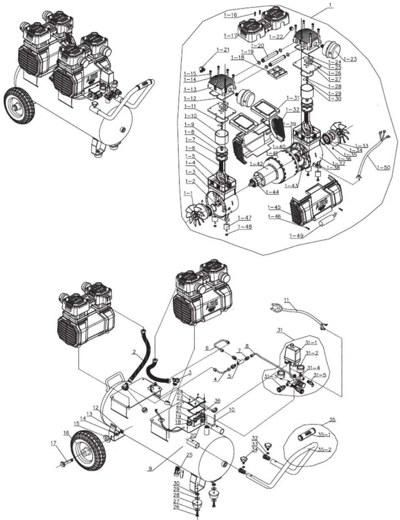
| No. | Description No. | Description No. | Description | ||||
| 1 | Motor and pump assembly 1-31 Cover 13 | Spring - Dia. 10 | |||||
| 1-1 | Fan 1-32 Cover A 14 | Washer - Dia. 10 | |||||
| 1-2 | Nut-M5 | 1-33 | Shaft seal | 15 | Washer - Dia. 45" Dia. 10"4 | ||
| 1-3 | Left crankcase | 1-34 | Bearing 6908 | 16 | Wheel - 10" | ||
| 1-4 | Adjusting washer | 1-35 | Bolt - M8*10 | 17 | Bolt - M10 | ||
| 1-5 | Bolt - M6*18 | 1-36 | Washer | 18 | Safety carriage - PG9 | ||
| 1-6 | Connecting rod | 1-37 | Right crankcase | 19 | Bolt - M4*10 | ||
| 1-7 | Piston cup | 1-38 | Protection ring | 20 | Safety carriage - PG11 | ||
| 1-8 | Binder plate | 1-39 | Bolt | 21 | Box | ||
| 1-9 | Bolt - M6*16 | 1-40 | Spring | 22 | Obturaling ring | ||
| 1-10 | Cylinder | 1-41 | Stator | 23 | Cover | ||
| 1-11 | Oblurating ring | 1-42 | Rotator | 24 | Bolt - M3*10 | ||
| 1-12 | Obturatoring ring | 1-43 | Washer - Dia. 10 | 25 | Drain cock | ||
| 1-13 | Cylinder head | 1-44 | Bearing 6204 | 26 | Bolt - M8*25 | ||
| 1-14 | Bolt- M6*70 | 1-45 | Cover B | 27 | Washer | ||
| 1-15 | Spring - Dia. 6 | 1-46 | Bolt M5*25 | 28 | Cushion foot | ||
| 1-16 | Boll - M4×16 | 1-47 | Vibration column- M8 | 29 | Washer | ||
| 1-17 | Head cover | 1-48 | Nut- M8 | 30 | Nut | ||
| 1-18 | Fixed block | 1-49 | Capacitor -35uf | 31 | Switch assembly | ||
| 1-19 | Oblurating ring | 1-50 | Motor electrical wire | 31-1 | Pressure switch | ||
| 1-20 | Connecting pipe | 2 | Pipe | 31-2 | Pressure gauge | ||
| 1-21 | Elbow | 3 | Check valve | 31-3 | Quick valve | ||
| 1-22 | Bolt-G1/2 | 4 | Unloading pipe | 31-4 | Support | ||
| 1-23 | Air filter | 5 | Tee joints | 31-5 | Safety valve | ||
| 1-24 | Bolt - M4*8 | 6 | Unloading pipe | 32 | Nut - M8 | ||
| 1-25 | Limit block | 7 | Connector | 33 | Block up | ||
| 1-26 | Valve | 8 | Unloading pipe | 34 | Bolt -M8 | ||
| 1-27 | Valve plate | 9 | Tank - 60 | 35 | Handle assembly | ||
| 1-28 | Valve | 10 | Electrical wire | 35-1 | Handle cover - Dia. 25 | ||
| 1-29 | Washer | 11 | Plug- 1.52*2.2m | 35-2 | Handle - Dia. 25 | ||
| 1-30 | Bolt | 12 | Nut - M10 | 36 | Close end wire connector |
CIRCUIT DIAGRAM
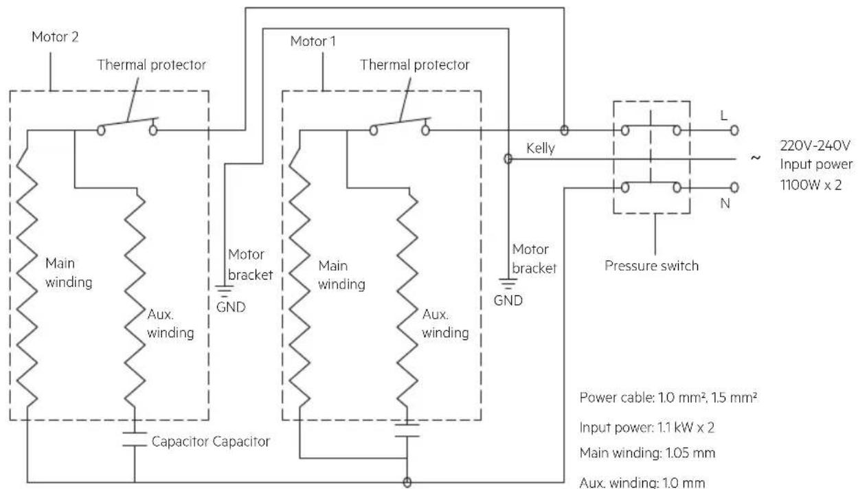
Power cable: 1.0 mm², 1.5 mm²
Input power: 1.1 kW x 2
Main winding: 1.05 mm
Aux. winding: 1.0 mm
Working capacitor: 450V/35uf
NITTO is a registered trademark owned by Nitto Kohki Co., Ltd
AEG
www.aegpowertools.com.au
www.aegpowertools.co.nz
Techtronic Industries Australia Pty Ltd
31 Gilby Road, Mount Waverley
VIC, 3149, Australia
Techtronic Industries N.Z. Limited
Unit C, 70 Business Parade South
Highbrook, Auckland 2013, New Zealand
20190326v1b
AEG is a registered trademark used under
license from AB Electrolux (publ).
- Important!
- REPLACEMENT PARTS
- WARNING!
- GENERAL SAFETY WARNINGS
- WARNING
- Read all instructions.
- WORK AREA SAFETY
- ELECTRICAL SAFETY
- PERSONAL SAFETY
- AIR COMPRESSOR USE AND CARE
- SERVICE
- Save these instructions. Refer to them frequently and use them to instruct other users. If you loan someone this tool, loan them these instructions also.
- AIR COMPRESSOR SAFETY WARNINGS
- RESIDUAL RISKS
- SPECIFIED CONDITIONS OF USE
- ASSEMBLY
- UNPACKING
- Packing list
- INSTALLING FRONT HANDLE
- See figure 2.
- INSTALLING FEET
- See figure 3.
- INSTALLING WHEELS
- See figure 4.
- INSTALLING AIR FILTERS
- See figure 5.
- OPERATION
- DANGER
- CAUTION
- TRANSPORTING THE AIR COMPRESSOR
- To move the air compressor:
- To transport the air compressor up or down stairs:
- ATTACHING/DISCONNECTING AIR HOSE
- To disconnect an air hose or an air tool:
- TURNING THE AIR COMPRESSOR ON/OFF
- USING THE AIR COMPRESSOR
- CHECKING THE PRESSURE RELIEF VALVE
- DRAINING THE TANK
- To drain:
- STORAGE
- MAINTENANCE
- GENERAL MAINTENANCE
- REPLACING AIR FILTERS
- Normal environment
- Heavy-dust environment
- To replace an air filter:
- Techtronic Industries Australia Pty Ltd
- Techtronic Industries N.Z. Limited
- SYMBOLS
- CIRCUIT DIAGRAM
- AEG
Brand : AEG
Model : AC3060S
Category : Compressor