
27DR-5 - Wall socket Karlik - Free user manual and instructions
Find the device manual for free 27DR-5 Karlik in PDF.


| Product Type | Wall Socket |
| Brand | Karlik |
| Model | 27DR-5 |
| Dimensions (H x W x D) | 80mm x 80mm x 45mm |
| Weight | 0.1 kg |
| Material | Thermoplastic, Brass contacts |
| Color | White |
| Rated Voltage | 250V AC |
| Rated Current | 16A |
| Frequency | 50/60 Hz |
| Number of Sockets | 2 |
| Grounding | Yes, with grounding pin |
| Child Protection | Shutters |
| Installation | Flush or surface mounting |
| Ingress Protection | IP20 |
| Operating Temperature | -5°C to 40°C |
| Certification | CE, RoHS |
| Cleaning | Wipe with dry cloth |
| Warranty | 2 years |
Frequently Asked Questions - 27DR-5 Karlik
User questions about 27DR-5 Karlik
0 question about this device. Answer the ones you know or ask your own.
Ask a new question about this device
Download the instructions for your Wall socket in PDF format for free! Find your manual 27DR-5 - Karlik and take your electronic device back in hand. On this page are published all the documents necessary for the use of your device. 27DR-5 by Karlik.
USER MANUAL 27DR-5 Karlik
ASSEMBLY MANUAL OF RTV AND RTV-SAT OUTLET SOCKETS
- Prepare end of the antenna cable for installation, i.e. strip the wire of the coaxial cable by cutting at the same height the external insulation, over-wrap and the centre of the cable. (picture no. 1)
- Unscrew the clamping bolt in the antenna outlet socket (picture no. 2).
- Insert the antenna cable so as blade of the socket enters between the over-wrap and the external insulation. Check if the wires of the cable are inserted into the input clamp in a correct way (picture no. 4).
- Tighten the clamping bolt in the antenna outlet socket (picture no. 5).
- For pass-through sockets - procedure for socket output is the same as for socket input.
- Insert the socket into the φ 60mm installation box and according to the type of box assembly the socket with either the spikes or the fastening screws.
- Place the frame with the cap on the main body of the outlet socket..

PICTURE NO.1

PICTURE NO.2
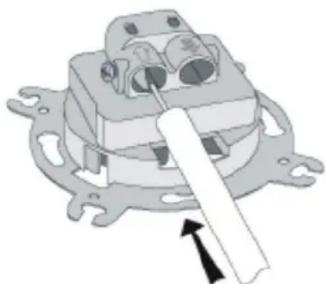
PICTURE NO.3

PICTURE NO.4

PICTURE NO.5
NOTE!
Assembly shall be held by a suitably qualified person with deactivated voltage and shall meet the national safety standards.


Brand : Karlik
Model : 27DR-5
Category : Wall socket