
RE-350 - Video projector CANON - Free user manual and instructions
Find the device manual for free RE-350 CANON in PDF.


User questions about RE-350 CANON
0 question about this device. Answer the ones you know or ask your own.
Ask a new question about this device
Download the instructions for your Video projector in PDF format for free! Find your manual RE-350 - CANON and take your electronic device back in hand. On this page are published all the documents necessary for the use of your device. RE-350 by CANON.
USER MANUAL RE-350 CANON
natural_image
Line drawing of a desktop computer with an overhead projector and monitor (no text or symbols)Please read this instruction manual carefully before operation. Store this manual in a readily accessible location for future reference.
Thank you for purchasing the Canon Video Visualizer RE-350.
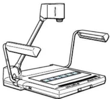
The RE-350 is a user-friendly portable image input device with a built-in video camera and a 12 x zoom lens. It projects images of flat documents, three-dimensional objects, film, etc., onto a video monitor. Here are the main features:
- Quality images can be immediately projected by the auto focus, auto white balance, and auto iris (automatic exposure) functions.
- This device has abundant video inputs and outputs, including VIDEO IN/OUT, S-VIDEO IN/OUT, RGB OUT, and external synchronization input.
- Simply by pressing a button, you can convert from negative to positive, or switch from color to black and white.
- Stereo sound is available.
- This device has a backlight that can easily project film and other transparencies.
- Functions of the RE-350 can be controlled via RS-232C connection.
To use this product correctly, please read this Instruction Manual carefully before operation.
Confirm that the package contains the following items:
- Canon Video Visualizer RE-350
- Power cord (6.6 ft/2 m) x 1
- Unit cover
- Instruction Manual
- Warranty Card
IMPORTANT WARNINGS
Following signs are shown on the product.
CAUTION
RISK OF ELECTRIC SHOCK DO NOT OPEN

The lightning flash with arrowhead symbol, within an equilateral triangle, is intended to alert the user to the presence of uninsulated “dangerous voltage” within the product’s enclosure that may be of sufficient magnitude to constitute a risk of electric shock to persons.
CAUTION: TO REDUCE THE RISK OF ELECTRIC SHOCK, DO NOT REMOVE COVER (OR BACK). NO USER-SERVICEABLE PARTS INSIDE. REFER SERVICING TO QUALIFIED SERVICE PERSONNEL.

The exclamation point, within an equilateral triangle, is intended to alert the user to the presence of important operating and maintenance (servicing) instructions in the literature accompanying the appliance.
- This Instruction Manual may not be copied, in whole or part, without prior consent of Canon.
- The content of this manual is subject to change without notice.
© Copyright 1996 CANON INC.
ALL RIGHTS RESERVED
WARNING: TO REDUCE THE RISK OF ELECTRIC SHOCK,

DO NOT EXPOSE THIS PRODUCT TO RAIN OR MOISTURE.
WARNING: TO REDUCE THE RISK OF ELECTRIC SHOCK

AND TO REDUCE ANNOYING INTERFERENCE, USE THE RECOMMENDED ACCESSORIES ONLY.
FCC NOTICE
Note: This equipment has been tested and found to comply with the limits for a Class B digital device, pursuant to Part 15 of the FCC Rules. These limits are designed to provide reasonable protection against harmful interference in a residential installation. This equipment generates, uses and can radiate radio frequency energy and, if not installed and used in accordance with the instructions, may cause harmful interference to radio communications. However, there is no guarantee that interference will not occur in a particular installation. If this equipment does cause harmful interference to radio or television reception, which can be determined by turning the equipment off and on, the user is encouraged to try to correct the interference by one or more of the following measures:
- Reorient or relocate the receiving antenna.
- Increase the separation between the equipment and receiver.
- Connect the equipment into an outlet on a circuit different from that to which the receiver is connected.
- Consult the dealer or an experienced radio/TV technician for help.
Do not make any changes or modifications to the equipment unless otherwise specified in the manual. If such changes or modifications are made, you could be required to stop operation of the equipment.
This digital apparatus does not exceed the Class B limits for radio noise emissions from a digital apparatus as set out in the interference-causing equipment standard entitled “Digital Apparatus”, ICES-003 of the Bureau of Industry and Science Canada.
The serial number of this product can be found on the back of the unit.
No other unit has the same serial number. You should record the number and other vital information here and retain this book as a permanent record of your purchase to aid identification in case of theft.
Date of Purchase
Dealer Purchased From
Dealer Address
Dealer Phone No.
Model No. RE-350
Serial No.
In these safety instructions the word “product” refers to the Canon Video Visualizer RE-350 and all its accessories.
- Read Instructions—All the safety and operating instructions should be read before the product is operated.
- Retain Instructions—The safety and operating instructions should be retained for future reference.
- Heed Warnings—All warnings on the product and in the operating instructions should be adhered to.
- Follow Instructions—All operating and maintenance instructions should be followed.
- Cleaning—Unplug this product from the wall outlet before cleaning.
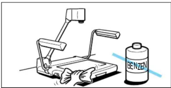
Wipe the product with a clean soft cloth. If necessary, put the cloth in diluted neutral detergent and wring it out well, before wiping the product. Finally, clean the product with a clean dry cloth. Do not use benzene, thinner or other volatile liquids or pesticides as they may damage the product's finish. When using chemically-treated cleaning cloths, observe their precautions accordingly.
natural_image
Illustration of a hand washing a water dispenser with a Benzen brand bottle nearby (no text or symbols on the diagram itself)- Accessories—Do not use non Canon approved accessories as they may be hazardous. Always use the specified connection cables and be sure to connect devices correctly.
- Water and Moisture—Hazard of electric shock—Do not use this product near water or in rainy/moist situations. Do not put a heater near this product.

natural_image
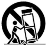
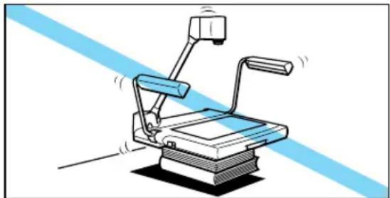
Line drawing of a mechanical device with lever and handle, no text or symbols present- Placing or Moving—Do not place this product on an unstable cart, stand, tripod, bracket or table. The
product may fall, causing serious injury to a child or adult and serious damage to the product. A product and cart combination should be
moved with care. Quick stops, excessive force, and uneven surfaces may cause the product and cart combination to overturn.
natural_image
Illustration of a mechanical device with lever and base, no text or symbols present- Power Sources—This product should be operated only from the type of power source indicated on the marking label. If you are not sure of the type of power supply in your home, consult your product dealer or local power company.
- Grounding—This product is equipped with a 3-pronged grounding plug (the plug has a third grounding pin).
The 3-pronged grounding plug will fit into a grounding type power outlet. This is a safety feature. If you are unable to insert the plug into the outlet, contact your electrician to replace your obsolete outlet. Do not defeat the safety purpose of the grounding-type plug.
- Power-Cord Protection—Power cords should be routed so that they are not likely to be walked on or pinched by items placed upon or against them. Pay particular attention to plugs, and the point from which the cords exit the product.
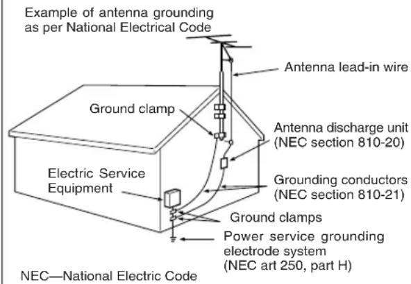
- Outdoor Antenna Grounding—If an outside antenna is connected to the product, be sure the antenna is grounded so as to provide some protection against voltage surges and built-up static charges. Section 810 of the National Electrical Code, ANSI/NFPA No. 70—1984, provides information with respect to proper grounding of the mast and supporting structure, grounding of the lead-in wire to an antenna discharge unit, size of grounding conductors, location of antenna discharge unit, connection to grounding electrodes, and requirements for the grounding electrode. See figure 1.
Fig. 1
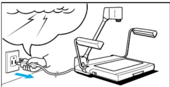
- Lightning—For added protection of this product during a lightning storm, or when it is left unattended and unused for long periods of time, disconnect it from the wall outlet. This will prevent damage to the product due to lightning and power-line surges.
natural_image
Illustration of a hand using a power outlet to connect to a device with a lightning bolt, no text or symbols present.- Power Lines—An outside antenna system should not be located in the vicinity of overhead power lines or other electric light or power circuits, or where it can fall into such power lines or circuits. When installing an outside antenna system, extreme care should be taken to keep from touching such power lines or circuits as contact with them might be fatal.
- Overloading—Do not overload wall outlets and extension cords as this can result in a risk of fire or electric shock.
- Objects and Liquid Entry—Never push objects of any kind into this product through openings as they may touch dangerous voltage points or short out parts that could result in a fire or electric shock. Be careful not to spill liquid of any kind onto the product.
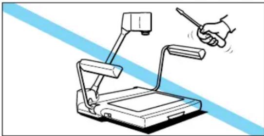
- Servicing—Do not attempt to service this product yourself as opening or removing covers may expose you to dangerous voltage or other hazards. Refer all servicing to qualified service personnel.
natural_image
Illustration of a handheld electronic device with lever mechanism and hand gesture (no text or symbols)- Damage Requiring Service—Disconnect the product from the wall outlet and refer servicing to qualified service personnel under the following conditions:
a. When the power-supply cord or plug is damaged.
b. If any liquid has been spilled onto, or objects have fallen into the product.
c. If the product has been exposed to rain or water.
d. If the product does not operate normally even if you follow the operating instructions, adjust only those controls that are covered by the operation instructions. Improper adjustment of other controls may result in damage and will often require extensive work by a qualified technician to restore the product to its normal operation.
e. If the product has been dropped or the cabinet has been damaged.
f. When the product exhibits a distinct change in performance. This indicates a need for service.
-
Replacement Parts—When replacement parts are required, be sure the service technician has used replacement parts that are specified by Canon or that have the same characteristics as the original part. Unauthorized substitutions may result in fire, electric shock or other hazards.
-
Safety Check—Upon completion of any service or repairs to this product, ask the service technician to perform safety checks to determine that the product is in safe operating order.

IMPORTANT SAFETY INSTRUCTIONS...... 3
- NOMENCLATURE AND FUNCTIONS 6
- ASSEMBLING, STORING AND CONNECTION ... 9
- OPERATION 12
Manual Focusing....13
Film Projection....13
Readjusting the White Balance 14
Converting from Negative to Positive....14
Projecting Black-and-White Documents....15
Adjusting Brightness and Picture Quality......15
- SYSTEM CONSTRUCTION 16
Outputting to a RGB Monitor 16
To Control by a Computer 16
Changing to Pictures via External Input Equipment.....17
Using a Microphone....17
Recording by VCR 18
Using External Synchronization....19
Functions Controlled by a Computer....20
- TROUBLESHOOTING 21
- SPECIFICATIONS 22
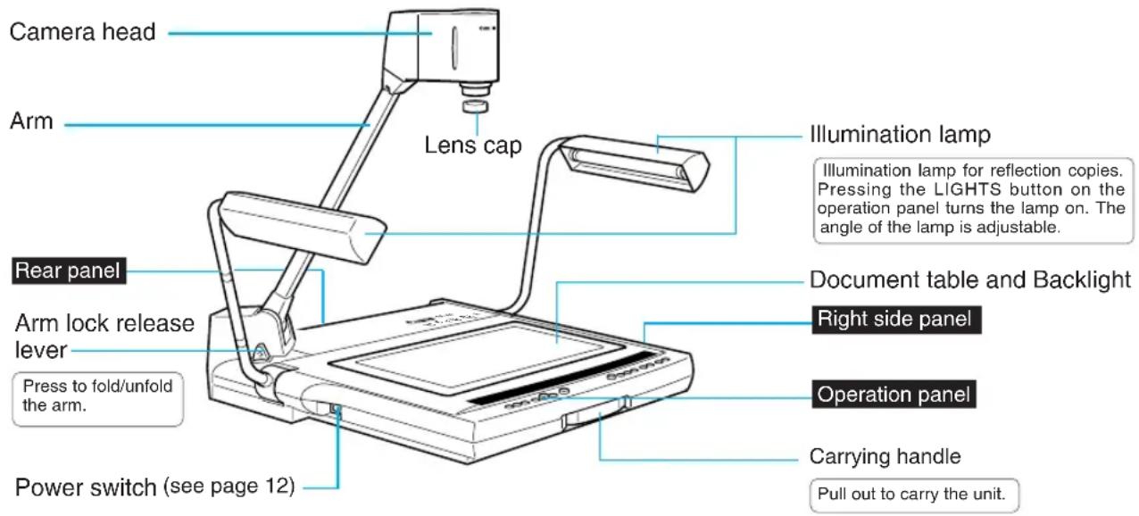
1 NOMENCLATURE AND FUNCTIONS
NOTICE

After turning the power OFF, wait at least 5 seconds before turning the power ON again. Turning the power ON too soon may cause a malfunction.

The illumination lamps do not light up immediately after the LIGHTS button is pressed. To protect the lamps, the system preheats for 3 seconds, then turns the lamps on.
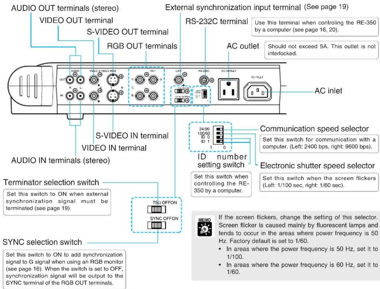
Rear Panel
See page 16 for system construction.
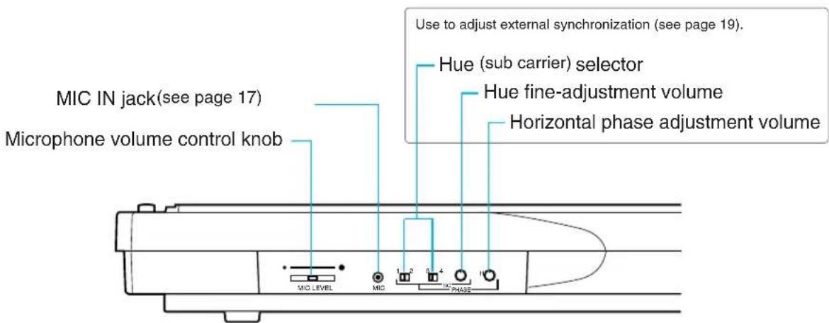
Right Side Panel
Operation Panel
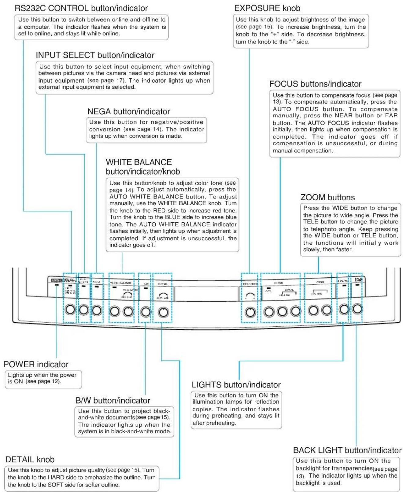

The illumination lamps and the backlight cannot be used at the same time.
2 ASSEMBLING, STORING AND CONNECTION
Assembling
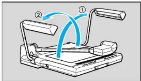
1 Unfold and raise the pair of illumination lamps.
Raise the right-hand illumination lamp first, then the left-hand illumination lamp (①→②).
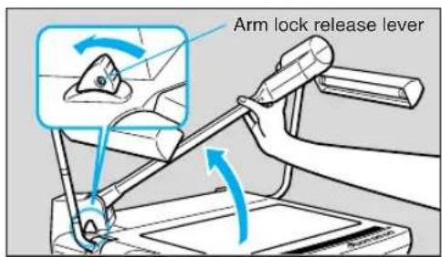
2 Press the arm lock release lever, and raise the arm until it stops.
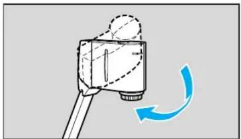
3 Direct the camera head towards the document table.
natural_image
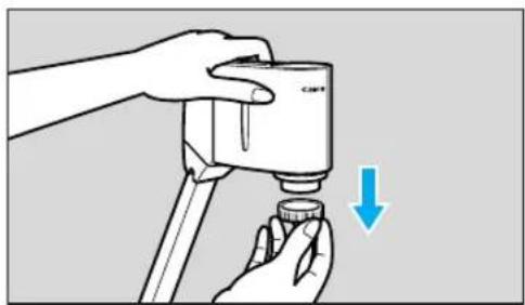
Diagram of a camera mounted on a tripod with a blue curved arrow indicating rotation (no text or symbols)4 Remove the lens cap.
Keep the lens cap in a safe place.
natural_image
Illustration of a hand using a CAFM device to press down a small cylindrical component, with a blue arrow indicating downward motion (no text or symbols present)Storing
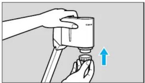
1 Put the lens cap to the lens.

Be sure to turn the power OFF before storing the unit.
natural_image
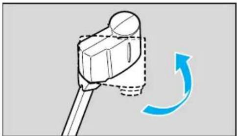
Illustration of a hand using a handheld device to press or install a small component, with an upward arrow indicating motion (no text or symbols present)2 Direct the camera head sideways until it stops.
natural_image
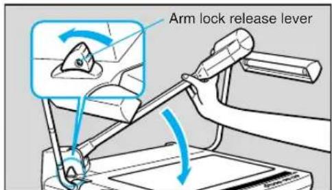
Diagram of a mechanical component with a blue curved arrow indicating rotation (no text or symbols)3 Hold the arm with your right hand and press the arm lock release lever, then pull the arm down to the document table very carefully.

Be sure to hold the arm with your right hand, then press the arm lock release lever.
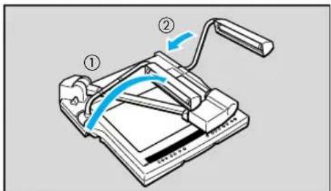
4 Fold the pair of illumination lamps very carefully.
Fold the left-hand illumination lamp first, then the right-hand illumination lamp (①→②).

Do not touch the fluorescent lamps after the illumination lamps are turned off, as they may still be hot.
natural_image
Illustration of a computer monitor mounted on a cabinet (no text or symbols visible)
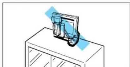
Put the supplied unit cover on the RE-350 when the unit is not in use. The unit cover has a pocket to store cords.

Place the unit horizontally when storing it. If the unit is stored vertically, it may fall down and cause injury or malfunction. When carrying the unit, turn the power OFF, disconnect the cords, fold the arm and the illumination lamps, and pull out the carrying handle.
Connection
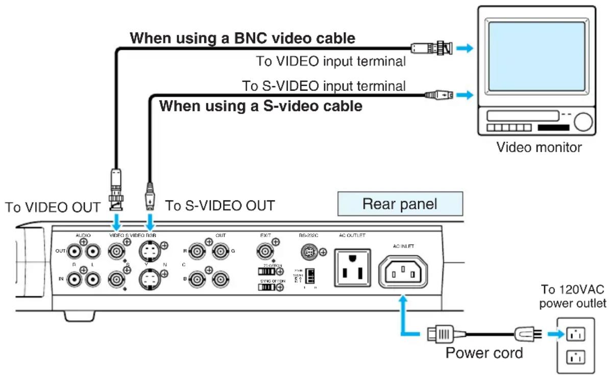
To connect the RE-350 to a monitor, use a commercially available BNC video cable. To use a video monitor with the S-VIDEO terminal, use a commercially available S-video cable. Using S-video enhances picture quality. Use the power cord included with the RE-350.
flowchart
graph TD
    A["When using a BNC video cable"] -->|To VIDEO input terminal| B["Video monitor"]
    C["When using a S-video cable"] -->|To S-VIDEO input terminal| B
    D["Power cord"] --> E["To 120VAC power outlet"]
    F["To VIDEO OUT"] --> G["Back panel"]
    H["Power cord"] --> I["Power cord"]
    J["Audio"] --> K["OUT"]
    L["VIDEO S VIDEO RGB"] --> M["R"]
    N["V"] --> O["N"]
    P["C"] --> Q["B"]
    R["OUT"] --> S["G"]
    T["EXIT"] --> U["RS-25C"]
    V["AC OUTLET"] --> W["AC INLET"]
    X["STNG OUTON"] --> Y["STNG OUT"]
    Z["Power cord"] --> AA["Power cord"]

To protect the RE-350 as well as other equipment in use, make sure all the equipment (if any) is OFF before connecting cables. Always hold onto the plug section whenever connecting/disconnecting the cables.

- See page 16 for connecting equipment. For details of operation, refer to the instruction manual of the equipment to be used.
- If your computer has AV compatibility, you can input images to the computer by connecting your computer to the RE-350 with video cables. If your computer is not AV compatible, a video capture board is necessary.
■ Installation Site and Environment
- Connect the RE-350 to a correct electronic source.
Source voltage: 120VAC ± 10%
Source frequency: 60 Hz
- Install the RE-350 in a proper environment.
Temperature: 41^ F – 95^ F ( 5^ C – 35^ C)
Humidity: 85% max (without condensation)
1
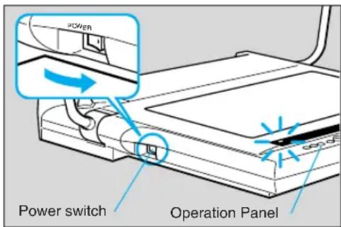
Turn the power ON.
When the power of the RE-350 is turned ON, the POWER indicator on the operation panel lights up.

- White balance will be automatically adjusted when the power is turned ON. The AUTO WHITE BALANCE indicator flashes initially, then lights up when adjustment is completed. If adjustment is unsuccessful, the indicator goes off (see page 14). Focus can also be automatically compensated.
- White balance will be automatically readjusted if the illumination lamps or backlight are turned on.
2
Turn ON the power source of the other equipment to be used.
Either the power of the RE-350 or other equipment may be turned on first.
3
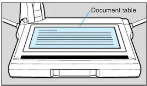
Put the document at the center of the document table.
If no image is displayed, check to see that the lens cap has been removed.

To appropriately adjust the white balance, turn ON the power of the RE-350 before putting the document on the table.
4
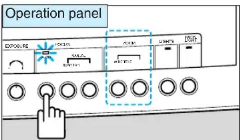
Press the AUTO FOCUS button to focus.
The AUTO FOCUS indicator flashes initially, then lights up when adjustment is completed. If adjustment is unsuccessful, the indicator goes off (see page 13).
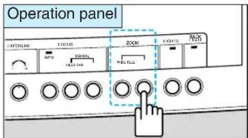
After placing the document, press the ZOOM buttons (WIDE button or TELE button) to adjust the image to the desired size. Whenever the image cannot be focused properly, press the AUTO FOCUS button.
5
When operation is completed, turn the power OFF.
The POWER indicator goes off. The illumination lamps or backlight will go off (if they are on). Also turn OFF the power of other equipment.

After turning the power OFF, wait at least 5 seconds before turning the power ON again. Turning the power ON too soon may cause a malfunction.
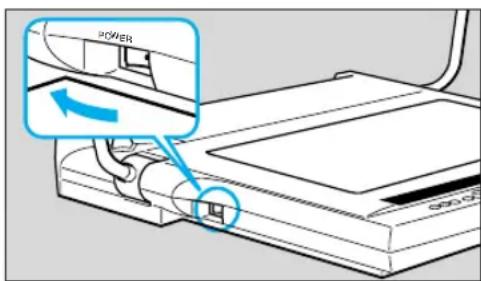

The power of the RE-350 should be turned OFF when the unit is not used. Disconnect the power cord if the unit will not be used for extended periods.
Manual Focusing
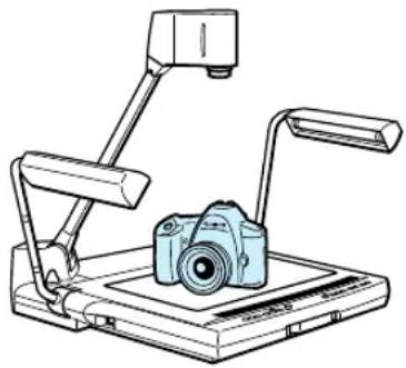
When trying to focus correctly or focusing on a particular point of three-dimensional objects, you can achieve focusing by pressing the manual focusing buttons. The manual focusing is valid up to approx. 2^-9/16 inch (65mm) above the document table.
natural_image
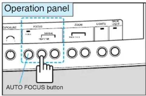
Line drawing of a desktop computer with an open camera and two articulated arms (no text or symbols)Press the manual focusing buttons (NEAR and FAR buttons) when focusing the lens manually. During manual focus mode, the AUTO FOCUS indicator turns off.
To return to auto focus mode, press the AUTO FOCUS button.
■ Undesirable objects for focusing
Although the auto focus function of the RE-350 is very accurate, objects such as those listed below may present some difficulties. If the system cannot focus automatically, the AUTO FOCUS indicator goes off. If this happens, focus the lens manually using the NEAR button or the FAR button.
- Objects with a low reflection factor (such as a dark cloth, hair, etc.)
- Intangible objects (such as candle light, smoke, etc.)
- Objects having a glossy surface (telephone receiver, glassware, etc.)
- Objects viewed through glass.
Film Projection
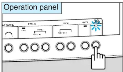
Use the backlight to project transparencies, such as OHP films, photographic negative and positive films and 35mm slides.
natural_image
Line drawing of a desktop computer with an overhead screen and stand (no text or symbols)Press the BACK LIGHT button to project transparencies. The BACK LIGHT indicator lights up and the document table glows. If the illumination lamps have been lighted, they will go off.
Pressing the BACK LIGHT button again, turns the backlight off.

- Project the film to full monitor size by using the zoom button. If light from the backlight appears in the monitor, the picture itself will not appear very sharp.
- If color tone seems unnatural, press the AUTO WHITE BALANCE button.
- If the auto focus function does not operate accurately with film, focus the lens manually.
- The illumination lamps and the backlight cannot be used at the same time.
Readjusting the White Balance
Readjust the white balance after changing the illumination, or when the color tone seems unnatural. Adjustment to a desired color tone can be made manually.
- To readjust the white balance, complete the following steps:
① Put some white paper on the document table.
② Project the white paper to full monitor size by pressing the ZOOM buttons (WIDE button or TELE button).
③ Press the AUTO WHITE BALANCE button.
- To adjust to the desired color tones, adjust manually by using the WHITE BALANCE knob. Turning the knob towards the RED side increases the red tones. Turning the knob to the BLUE side increases the blue tones.
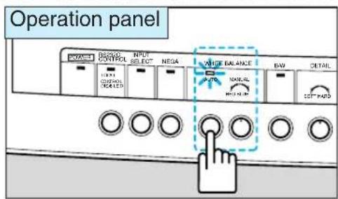

- When the AUTO WHITE BALANCE button is pressed, the AUTO WHITE BALANCE indicator flashes, then lights up when adjustment is completed. However, automatic adjustment may not be done, depending on the types of objects or light source. If adjustment is unsuccessful, the indicator goes off. If this happens, readjust according to method 1. mentioned above.
- Do not move the object while the AUTO WHITE BALANCE indicator is flashing otherwise adjustment will not be done correctly.
- Color tone changes are based on the position of the knob when the AUTO WHITE BALANCE button is pressed. For example, to emphasize the red tones, turn the knob towards the BLUE side, press the AUTO WHITE BALANCE button, then turn the knob towards the RED side.
Converting from Negative to Positive
1 Adjust projected image to full monitor size using the WIDE and TELE buttons.
2 Press the NEGA button for conversion.
During the conversion, the NEGA indicator will light. To return to normal mode, press the NEGA button again.

If color tones seem unnatural, press the AUTO WHITE BALANCE button, or adjust the white balance manually.
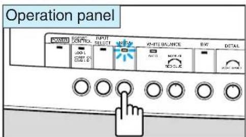

- By pushing the NEGA button, you can convert from black to white or vice versa. Also, if the image is already in color, you can convert from primary colors to complementary colors.
- Negative/positive conversion is only possible with pictures via the camera head.
Projecting Black-and-White Documents
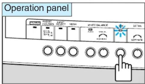
To project clearer black-and-white documents, press the B/W button. This setting also allows color documents to be displayed in black-and-white. Switching between color and black-and-white modes is possible only when projecting pictures via the camera head. Therefore, color pictures via external input equipment cannot be switched to black-and-white (see page 17). And also, color pictures of a RGB monitor cannot be switched to black-and-white.
To project black-and-white documents, press the B/W button. During black-and-white mode, the B/W indicator will light.
To return to normal mode, press the B/W button again.
Adjusting Brightness and Picture Quality
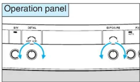
The brightness of the picture can be controlled by the EXPOSURE knob. When the document is dark, has low contrast, or is small and dim against brighter background, use the EXPOSURE knob to make the image clearer.
To adjust brightness, use the EXPOSURE knob. Turn the knob towards the “+” side to brighten the picture. Turn the knob toward the “-” side to darken the picture.
Use the DETAIL knob to adjust picture quality. Turn the knob toward the HARD side to emphasize the outline of an object. Turn the knob towards the SOFT side for a softer outline.
■ Character size when projecting a 13" x 10" size document
To fully display on the monitor a 13" x 10" size document with clear characters, refer to the samples shown below for size and thickness. The character samples are in actual scale (equivalent to 20 point photoset letters, and when outputting from the S-VIDEO OUT).
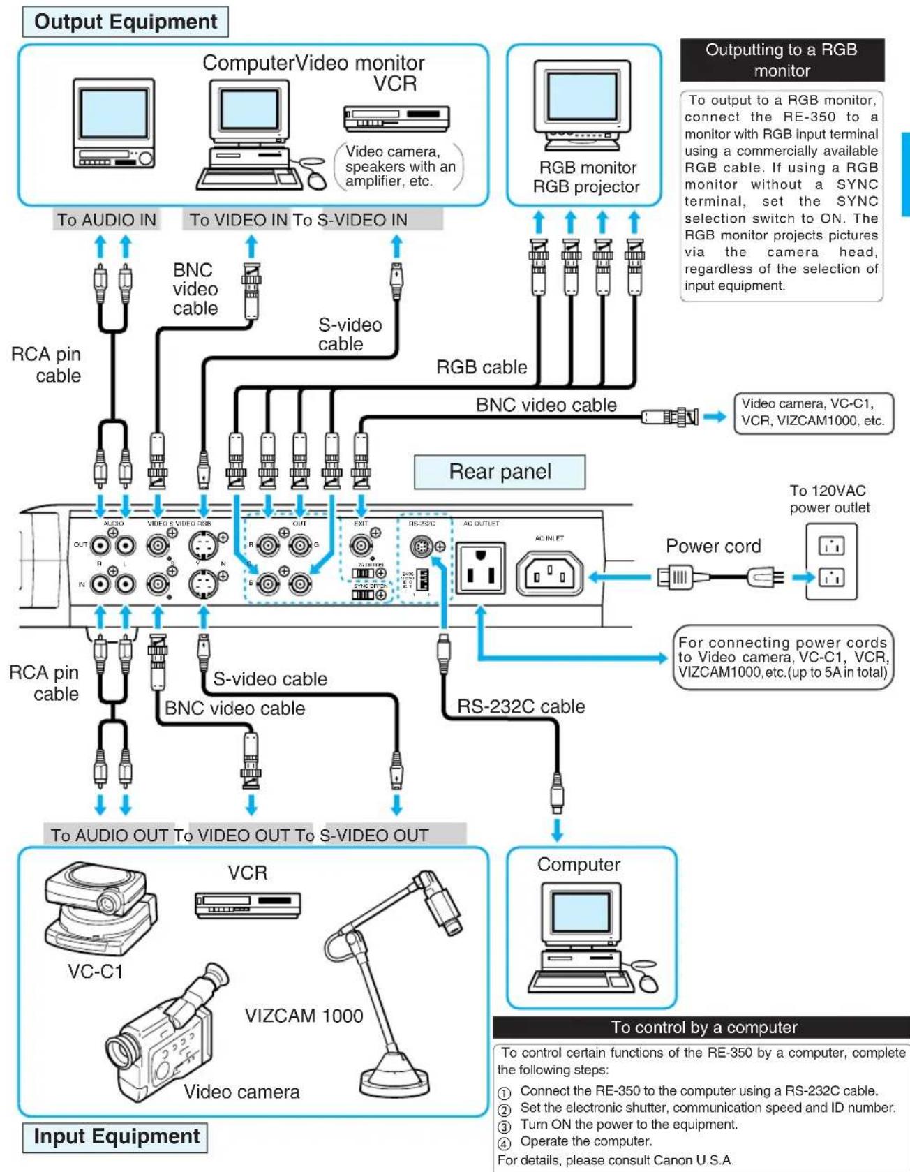
The RE-350 has abundant video input and output terminals. The equipment shown below can be connected to these terminals. Use the specified power cord. For other cords, use commercially available cables. For details of operation, refer to the instruction manual of the equipment to be used.
flowchart
graph TD
    A["Input Equipment"] --> B["Computer"]
    A --> C["VCR"]
    A --> D["VC-C1"]
    A --> E["VIZCAM 1000"]
    A --> F["Video camera"]
    A --> G["To audio OUT To video OUT To S-VIDEO OUT"]
    B --> H["Computer"]
    C --> I["VR/VR/VR/VR/VR/VR/VR/VR/VR/VR/VR/VR/VR/VR/VR/VR/VR/VR/VR/VR/VR/VR/VR/VR/VR/VR/VR/VR/VR/VR/VR/VR/VR/VR/VR/VR/VR/VR/VR/VR/VR/VR/VR/VR/VR/VR/VR/VR/VR/VR/VR"]
    D --> J["VR/C1"]
    D --> K["VR/C2"]
    D --> L["VR/C3"]
    D --> M["VR/C4"]
    D --> N["VR/C5"]
    D --> O["VR/C6"]
    D --> P["VR/C7"]
    D --> Q["VR/C8"]
    D --> R["VR/C9"]
    D --> S["VR/C10"]
    D --> T["VR/C11"]
    D --> U["VR/C12"]
    D --> V["VR/C13"]
    D --> W["VR/C14"]
    D --> X["VR/C15"]
    D --> Y["VR/C16"]
    D --> Z["VR/C17"]
    D --> AA["VR/C18"]
    D --> AB["VR/C19"]
    D --> AC["VR/C20"]
    D --> AD["VR/C21"]
    D --> AE["VR/C22"]
    D --> AF["VR/C23"]
    D --> AG["VR/C24"]
    D --> AH["VR/C25"]
    D --> AI["VR/C26"]
    D --> AJ["VR/C27"]
    D --> AK["VR/C28"]
    D --> AL["VR/C29"]
    D --> AM["VR/C30"]
    D --> AN["VR/C31"]
    D --> AO["VR/C32"]
    D --> AP["VR/C33"]
    D --> AQ["VR/C34"]
    D --> AR["VR/C35"]
    D --> AS["VR/C36"]
    D --> AT["VR/C37"]
    D --> AU["VR/C38"]
    D --> AV["VR/C39"]
    D --> AW["VR/C40"]
    D --> AX["VR/C41"]
    D --> AY["VR/C42"]
    D --> AZ["VR/C43"]
    D --> BA["VR/C44"]
    D --> BB["VR/C45"]
    D --> BC["VR/C46"]
    D --> BD["VR/C47"]
    D --> BE["VR/C48"]
    D --> BF["VR/C49"]
    D --> BG["VR/C50"]
    D --> BH["VR/C51"]
    D --> BI["VR/C52"]
    D --> BJ["VR/C53"]
    D --> BK["VR/C54"]
    D --> BL["VR/C55"]
    D --> BM["VR/C56"]
    D --> BN["VR/C57"]
    D --> BO["VR/C58"]
    D --> BP["VR/C59"]
    D --> BQ["VR/C60"]
    D --> BR["VR/C61"]
    D --> BS["VR/C62"]
    D --> BT["VR/C63"]
    D --> BU["VR/C64"]
    D --> BV["VR/C65"]
    D --> BW["VR/C66"]
    D --> BX["VR/C67"]
    D --> BY["VR/C68"]
    D --> BZ["VR/C69"]
    D --> CA["VR/C70"]
    D --> CB["VR/C71"]
    D --> CC["VR/C72"]
    D --> CD["VR/C73"]
    D --> CE["VR/C74"]
    D --> CF["VR/C75"]
    D --> CG["VR/C76"]
    D --> CH["VR/C77"]
    D --> CI["VR/C78"]
    D --> CJ["VR/C79"]
    D --> CK["VR/C80"]
    D --> CL["VR/C81"]
    D --> CM["VR/C82"]
    D --> CN["VR/C83"]
    D --> CO["VR/C84"]
    D --> CP["VR/C85"]
    D --> CQ["VR/C86"]
    D --> CR["VR/C87"]
    D --> CS["VR/C88"]
    D --> CT["VR/C89"]
    D --> CU["VR/C90"]
    D --> CV["VR/C91"]
    D --> CW["VR/C92"]
    D --> CX["VR/C93"]
    D --> CY["VR/C94"]
    D --> CZ["VR/C95"]
    D --> DA["VR/C96"]
    D --> DB["VR/C97"]
    D --> DC["VR/C98"]
    D --> DD["VR/C99"]
Changing to Pictures via External Input Equipment
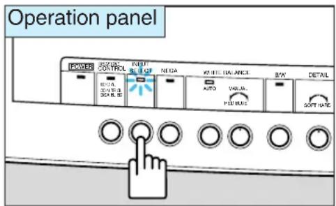
By connecting external input equipment, such as a VCR, video camera, etc, to the VIDEO IN or S-VIDEO IN terminals of the RE-350, you can project pictures via this equipment on the monitor. Pictures via the camera head and external input equipment can be changed alternately each time you press the INPUT SELECT button.
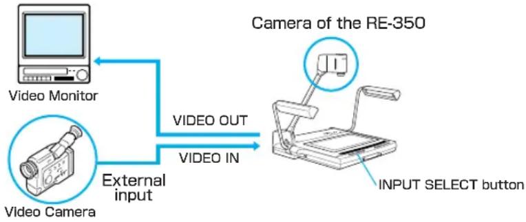
flowchart
graph LR
    A["Video Monitor"] -->|External input| B["Video Camera"]
    B -->|VIDEO OUT| C["Camera of the RE-350"]
    B -->|VIDEO IN| C
    C -->|INPUT SELECT button| D["Device with lever"]
To change to pictures via external input equipment, press the INPUT SELECT button.
The INPUT SELECT indicator lights up and then,
- Pictures via the equipment connected to the VIDEO IN terminal will be output to the VIDEO OUT terminal.
- Pictures via the equipment connected to the S-VIDEO IN terminal will be output to the S-VIDEO OUT terminal.
- Sound from the equipment connected to the AUDIO IN terminal will be output to the AUDIO OUT terminal.
To change to pictures via the camera head, press the INPUT SELECT button again.

- Regardless of the selection of input equipment, the RGB monitor projects pictures via the camera head.
- Negative/Positive conversion and Color/Black-and-White switching will not function with pictures via external input equipment.
- If a microphone is connected, sound from the microphone will also be output to the AUDIO OUT terminal.
Using a Microphone
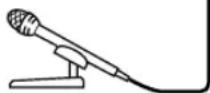
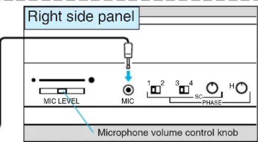
If you connect a microphone to the MIC IN terminal of the RE-350 and connect a monitor with speakers, sound can be output. Regardless of the selection of input equipment, sound from the microphone will be output to both R and L AUDIO OUT terminals in monaural mode. For operation details, refer to the instruction manual of the equipment to be used.
Use the microphone volume control knob to adjust the volume.
Sound from the microphone can be recorded together with pictures if outputting to a VCR.
Recording by VCR
When you connect a VCR to the output terminal of the RE-350, use a commercially available BNC video cable and RCA pin cable. If you connect a microphone, you can record audio together with pictures via the camera head onto a video tape. For details of operation, refer to the instruction manual for the equipment to be used.
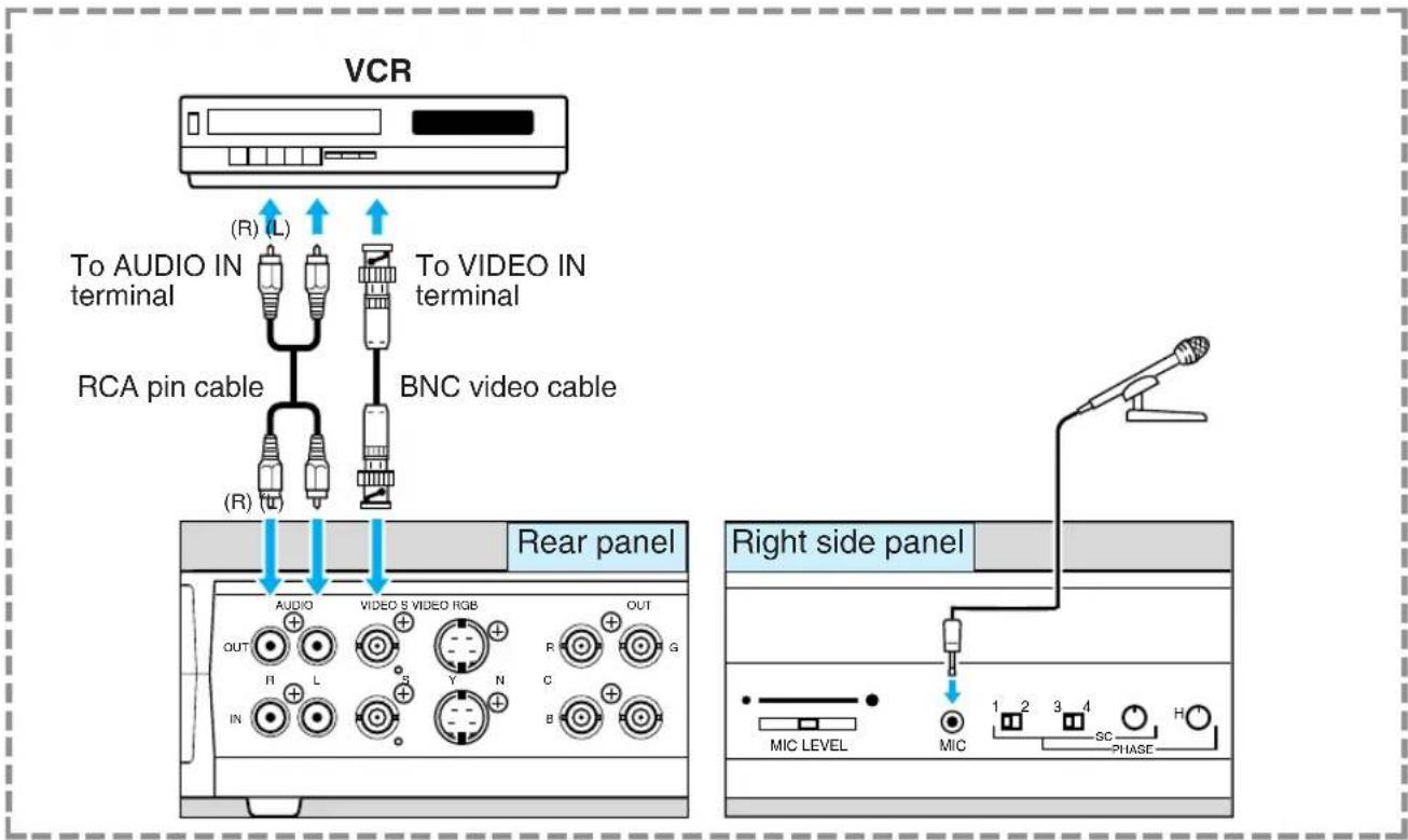


When you use a VCR with an S-video outlet, use S-video cables to connect to the S-video outlet. This will enable you to project a high quality image.
Using External Synchronization
The following illustration shows an example of connecting a camera for a video conferencing system to the RE-350. The picture will not flicker when the INPUT SELECT button is pressed to change from video captured by the camera of the RE-350 to that from external input and vice versa.
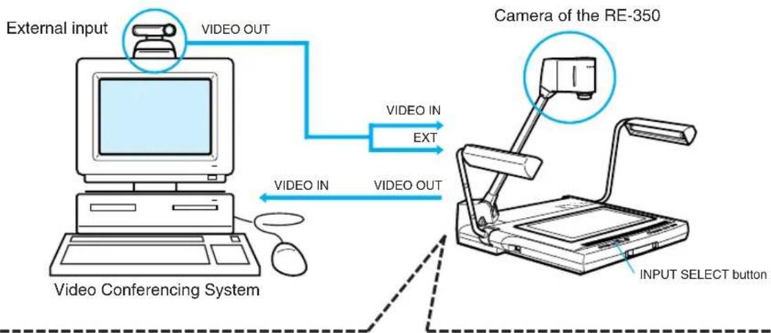
flowchart
graph TD
    A["External input"] -->|VIDEO OUT| B["Video Conferencing System"]
    B -->|VIDEO IN| C["Camera of the RE-350"]
    C -->|VIDEO OUT| D["Video Select button"]
    style A fill:#f9f,stroke:#333
    style B fill:#ccf,stroke:#333
    style C fill:#cfc,stroke:#333
    style D fill:#fcc,stroke:#333
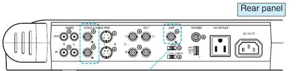
If the RE-350 is the terminating equipment in your system using multiple external synchronization input equipment, set this switch to ON.

External synchronization can be used for compositing images from multiple visualizers or video cameras on a single monitor, as well as for color measurements using a computer. For mobe information, please contact your dealer.
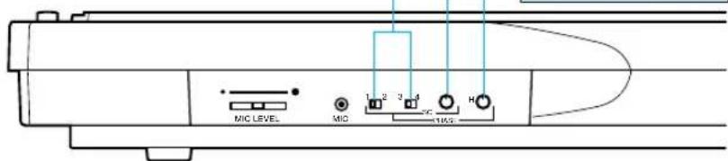
Switches for adjusting horizontal phase and hue.
Hue selector
Set the selector according to the hue of the reference signal so that the image hue matches the document hue.
| Phase | Swich position | |||
| 0° | 1 | 2 | 3 | |
| 90° | 1 | 2 | 3 | |
| 180° | 1 | 2 | 3 | |
| 270° | 1 | 2 | 3 | |
Hue fine-adjustment volume
Use this volume for fine-adjustment after changing the hue with the hue selector.
Horizontal phase adjust volume
Use this volume to align the horizontal phase when mixing pictures.
Right side panel
Functions Controlled by a Computer
The following functions can be controlled by a computer. For more information, please contact Canon U.S.A.
| Category | Abbreviation | Meaning | |
| Camera control system | Zoom lens control | WIDE: standardWIDE: fine-adjustmentTELE: standardTELE: fine-adjustmentZOOM: stopZOOM: positioningZOOM: output positionZOOM AF WIDE: standardZOOM AF TELE: standard | The zoom lens starts moving towards the wide-angle side at a standard speed.The zoom lens moves towards the wide-angle side at a slow speed.The zoom lens moves towards the telephoto side at a standard speed.The zoom lens moves toward the telephoto angle side at a slow speed.The zoom lens stops.The zoom lens moves to a specified position.Outputs the current position of the zoom lens.Perform the AUTO FOCUS function as soon as the zoom lens stop moving.Perform the AUTO FOCUS function as soon as the zoom lens stop moving. |
| Focus control OP | AFNEAR: standardNEAR: fine-adjustmentFAR: standardFAR: fine-adjustmentFOCUS: stop | Performs one-push autofocus.The focus lens starts moving towards the NEAR side at a standard speed.The focus lens moves toward the NEAR side at a slow speed.The focus lens starts moving towards the FAR side at a standard speed.The focus lens moves toward the FAR side at a slow speed.The focus lens stops. | |
| White balance setting | OP AWBWB: adjustment | Performs one-push auto white balance.Adjusts color tone. | |
| Exposure compensation | EXP: compensation Compensates exposure. | ||
| Outline adjustment | DETAIL: adjustment Adjusts picture quality of video signal. | ||
| Negative/positive conversion | POSI (normal mode)NEGA (conversed mode) | Outputs video signal in normal mode.Outputs video signal in conversed mode. | |
| Color/black and white switching | COLORB/W | Outputs video signal in color.Outputs video signal in black and white. | |
| System control | Input signal selection | CAMERAEXTERNAL | Selects the internal camera as input signal.Selects external video signal as input signal. |
| Illumination control | LIGHTS: ONLIGHTS: OFFBACKLIGHT: ONBACKLIGHT: OFF | Turns the illumination lamps on.Turns the illumination lamps off.Turns the backlight on.Turns the backlight off. | |
| LED control Operate LED: NORMALED in normal mode.LED: ONLED: OFFLED: BLINK | Turns a specified LED on forcibly.Turns a specified LED off forcibly.Blinks a specified LED forcibly. | ||
| Communication control | OFFLINESILENCENOTIFICATION | Sets the RE-350 to offline mode.Sets the RE-350 to silence mode.Sets the RE-350 to notification mode. | |
| Output information | STATUS: cameraSTATUS: switchSTATUS volumeDATA: machine nameDATA: ROM version | Outputs the status of the RE-350.Outputs the status of each switch.Outputs the position of each volume.Outputs identification data of device name.Outputs identification data of version. | |
To utilize the computer control features of the RE-350 a program developers kit is available from Canon U.S.A. The developers kit provides a guide for computer software programmers to create customized software to control camera functions.
5 TROUBLESHOOTING
If the RE-350 does not function properly, check the following points before contacting your dealer.
| Problem | Possible cause | Reference page |
| No image appears on the monitor | The lens cap has not been removed. 9The power of the RE-350 or other equipment has not been 12 turned ON.Connection may be incorrect. 16The input source is not selected correctly. 17 | |
| The picture cannot be focused correctly | The document may be too dark or glowing. 13Strong light may be reflected on the screen. 13The object has low contrast. 13Focusing has been set in manual mode. | 13 |
| Pictures appear reddish/bluish | The white balance has not been adjusted. 14The color tone of the video monitor is not correct. — | |
| Pictures are too bright/dark | Exposure of the RE-350 or monitor has not been adjusted 15 correctly.The object is not illuminated properly. — | |
| Pictures appear with flicker | The electronic shutter speed selector has been set 7 incorrectly. | |
| The input source cannot be changed | The power of the RE-350 or other equipment has not been 12 turned ON.Connection may be incorrect. 16 | |
| Pictures do not change to black and white | Pictures via external input equipment have been projected. 17 | |
| The illumination lamps do not light up immediately when the LIGHTS button is pressed | To protect the lamps, the system preheats for 3 seconds, then the lamps light up. During preheating, the LIGHT indicator flashes. This is not a malfunction. — | |
| The RE-350 cannot be controlled by a computer | The power of the RE-350 or other equipment has not been 12 turned ON.Connection may be incorrect. 16Incorrect operation may be the cause. — |
If the problem cannot be solved after checking the above points, contact your dealer.

The fluorescent illumination lamps and backlight are consumables. Replace with a new lamp if a lamp starts flickering or becomes dark. For details of replacement, consult your dealer.
| Video signal | Conforms to NTSC color format |
| Pickup element | 1/3-inch CCD |
| Total number of pixels | 410,000 pixels |
| Synchronization | Internal/external |
| Horizontal resolution | 450 TV lines |
| Vertical resolution | 350 TV lines |
| S/N ratio | 46 dB |
| Lens | f=5.4 mm - 64.8 mm, F1.8 - 2.8 (8-group, 10-element) |
| Ranges | 12^-51/_64 " x 9^-29/_64 " to 1^-5/_16 " x ^63/_64 " (325 x 240mm to 33.5 x 25mm) |
| Zoom | 12 x power zoom, 2-step speed |
| Focusing | One-push auto/manual |
| Iris adjustment | Auto/manual (fine-adjustable ±2 EV) |
| White balance | Auto/one-push-auto/manual |
| Illumination lamp | 6 W fluorescent lamp x 2, high-frequency lighting, angle-adjustable |
| Backlight | 6 W fluorescent lamp x 2, high-frequency lighting |
| Input sources | Internal camera/external input equipment |
| External synchronization | Input conditions: Composite video VBS (75 ~Ω imbalance)SYNC: 0.3 ±0.1 V, burst: 0.3 ±0.1 VFrequency range: H: 15.73426 kHz ±0.35 HzSC: 3.579545 MHz ±80 HzHorizontal phase adjustment: Manual (0 μs to 2 μ)Hue (sub carrier) adjustment: Manual ( 0^ to 360^ ) |
| Electronic shutter | DIP switch, 1/60 and 1/100 sec. |
| Communication speed | DIP switch, 2400 and 9600 bps. |
| Other functions | Negative/Positive conversion, Color/Black-and-White switching, Microphone mixing |
| Input/output terminals | VIDEO IN: BNC connector x 1, input impedance: 75 ΩVIDEO OUT: BNC connector x 1, output impedance: 75 ΩS-VIDEO IN: 4-pin mini-DIN x 1, input impedance: 75 ΩS-VIDEO OUT: 4-pin mini-DIN x 1, output impedance: 75 ΩRGB OUT: BNC connector x 4, output impedance: 75 ΩExternal synchronization input: BNC connector x 1, input impedance: 75 Ω/high impedanceAUDIO IN: RCA pin jack x 2 (stereo)AUDIO OUT: RCA pin jack x 2 (stereo)MIC IN mini-jack x 4, input impedance: 450 – 1,200 Ω, -68 dBRS-232C serial interface x 1AC input: 120 VAC, 60HzAC outlet: 120 VAC, 5A max., 60Hz, not interlocked |
| Power source | 120 VAC ±10%, 60Hz |
| Power consumption | Approx. 33 W |
| Dimensions | Operating position: 28^-2/_5 "(W) x 20^-3/_5 "(D) x 21^-4/_5 "(H)722(W) x 524.8(D) x 556(H)mmFolded position: 19- ^1/_8 "(W) x 20^-3/_5 "(D) x 7^-1/_5 "(H)486(W) x 524.8(D) x 183(H)mm |
| Weight | Approx. 22 lbs (10 kg) |
| Operating environment | Temperature: 41°F-95°F (+5°C - +35°C)Relative humidity: 20% - 85% (no condensation) |
- Weight and dimensions are approximate.
- Errors and omissions excepted.
- Specifications and design of the product are subject to change without notice.
-
Canon is a registered trademark of Canon Inc.
-
Weight and dimensions are approximate.
- Errors and omissions excepted.
- Specifications and design of the product are subject to change without notice.
- Canon is a registered trademark of Canon Inc.
- Confirm that the package contains the following items:
- IMPORTANT WARNINGS
- CAUTION
- FCC NOTICE
- IMPORTANT SAFETY INSTRUCTIONS...... 3
- NOMENCLATURE AND FUNCTIONS
- Rear Panel
- Right Side Panel
- Operation Panel
- ASSEMBLING, STORING AND CONNECTION
- Assembling
- Unfold and raise the pair of illumination lamps.
- Press the arm lock release lever, and raise the arm until it stops.
- Direct the camera head towards the document table.
- Remove the lens cap.
- Storing
- Put the lens cap to the lens.
- Direct the camera head sideways until it stops.
- Hold the arm with your right hand and press the arm lock release lever, then pull the arm down to the document table very carefully.
- Fold the pair of illumination lamps very carefully.
- Connection
- ■ Installation Site and Environment
- 1
- Turn the power ON.
- 2
- Turn ON the power source of the other equipment to be used.
- 3
- Put the document at the center of the document table.
- 4
- Press the AUTO FOCUS button to focus.
- 5
- When operation is completed, turn the power OFF.
- Manual Focusing
- ■ Undesirable objects for focusing
- Film Projection
- Readjusting the White Balance
- Converting from Negative to Positive
- Projecting Black-and-White Documents
- Adjusting Brightness and Picture Quality
- ■ Character size when projecting a 13" x 10" size document
- Changing to Pictures via External Input Equipment
- Using a Microphone
- Recording by VCR
- Using External Synchronization
- Switches for adjusting horizontal phase and hue.
- Hue selector
- Hue fine-adjustment volume
- Horizontal phase adjust volume
- Functions Controlled by a Computer
- TROUBLESHOOTING
Brand : CANON
Model : RE-350
Category : Video projector