
CNRFGWA-418 - Récepteur radio sans fil Crestron - Free user manual and instructions
Find the device manual for free CNRFGWA-418 Crestron in PDF.


| Product Type | Wireless RF Gateway |
| Model Number | CNRFGWA-418 |
| Brand | Crestron |
| Dimensions | 5.0 x 4.0 x 1.5 inches (127 x 102 x 38 mm) |
| Weight | 0.5 lbs (0.23 kg) |
| Power Supply | Power over Ethernet (PoE) IEEE 802.3af or external 24V DC |
| Frequency Band | 2.4 GHz |
| Wireless Range | Up to 150 ft (45 m) indoors |
| Supported Protocols | Cresnet, Crestron RF, Zigbee (optional) |
| Maximum Devices | Up to 100 wireless devices |
| Security | AES-128 encryption |
| LED Indicators | Power, Link, Activity |
| Mounting | DIN rail or surface mount |
| Operating Temperature | 32° to 104°F (0° to 40°C) |
| Maintenance | Keep clean and dry; no lubrication required |
| Repairability | Not user-serviceable; contact Crestron for service |
Frequently Asked Questions - CNRFGWA-418 Crestron
User questions about CNRFGWA-418 Crestron
0 question about this device. Answer the ones you know or ask your own.
Ask a new question about this device
Download the instructions for your Récepteur radio sans fil in PDF format for free! Find your manual CNRFGWA-418 - Crestron and take your electronic device back in hand. On this page are published all the documents necessary for the use of your device. CNRFGWA-418 by Crestron.
USER MANUAL CNRFGWA-418 Crestron
Wireless RF Receiver
Operations Guide
This document was prepared and written by the Technical Documentation department at:

CRESTRON
Crestron Electronics, Inc.
15 Volvo Drive
Rockleigh, NJ 07647
1-888-CRESTRON
Contents
Wireless RF Receiver: CNRFGWA 1
Introduction ...... 1
Functions and Features....1
Specifications 2
Physical Description....2
Industry Compliance 4
Setup 5
Network Wiring....5
Identity Code....5
Hardware Hookup 6
Programming Software....6
Earliest Version Software Requirements for the PC 7
Programming with SIMPL Windows 7
Uploading 7
Communication Settings 8
Uploading a SIMPL Windows Program....10
Problem Solving 11
Troubleshooting....11
Further Inquiries....12
Future Updates 12
Appendix: Optimum RF Reception Guidelines....13
Minimize Interference 13
Gateway Placement....13
Antenna Orientation 13
Return and Warranty Policies....15
Merchandise Returns / Repair Service 15
CRESTRON Limited Warranty....15
Wireless RF Receiver: CNRFGWA
Introduction
Functions and Features
The CNRFGWA wireless one-way radio frequency (RF) gateway/receiver (gateway) is designed to operate in a Crestron ® 2-Series or CNX control system. The gateway is available in two versions: one operates at 433.92 MHz; the other, CNRFGWA-418, operates at 418 MHz. Except for operating frequency, the units are functionally identical.
The gateway receives RF signals from one or more wireless one-way touchpanels such as the ST-1550, ST-1550C, ST-1700C, and MT-500C (418 MHz only), and wireless remotes such as the CNWM, CNRFT-32A and 48A, and CNRFHT-15A and 30A.
The CNRFGWA gateway translates the received signals into commands for transmission over the Crestron network (Cresnet ® ). Up to 15 touchpanels or 240 wireless remotes (or some combination of the two) can communicate with one gateway. If more touchpanels or remotes are needed, more gateways (up to 252) may be added to the system. However, when multiple gateways are used, the units must be located at least 50 feet from each other.
Functional Summary
• One-way RF receiver/gateway
- Crystal locked tuning for reliable reception. Two frequencies available:
- 433.92 MHz
- 418 MHz
• Reception range up to 300 feet
- Up to 15 wireless touchpanels and/or 240 wireless remotes can communicate with one gateway
Specifications
The table below is a summary of specifications for the CNRFGWA.
Specifications of the CNRFGWA
| SPECIFICATION | DETAILS |
| Power Requirements 3 Watts (0.125A @ 24VDC) | |
| Communications One-way high frequency RF (433.92 or 418 MHz) | |
| Operating Range Up to 300 feet | 1 |
| Default Net ID 24 | |
| Control System Update Files2,3,4 | |
| 2-Series Control System | Version C2-2.000.CUZ or later |
| CEN/CN-TVAV | Version 5.10.13V.UPZ or later |
| CNMSX-AV/PRO | Version 5.01.35X.UPZ or later |
| CNRACKX/-DP | Version 5.01.35W.UPZ or later |
| ST-CP | Version 4.02.04S.UPZ or later |
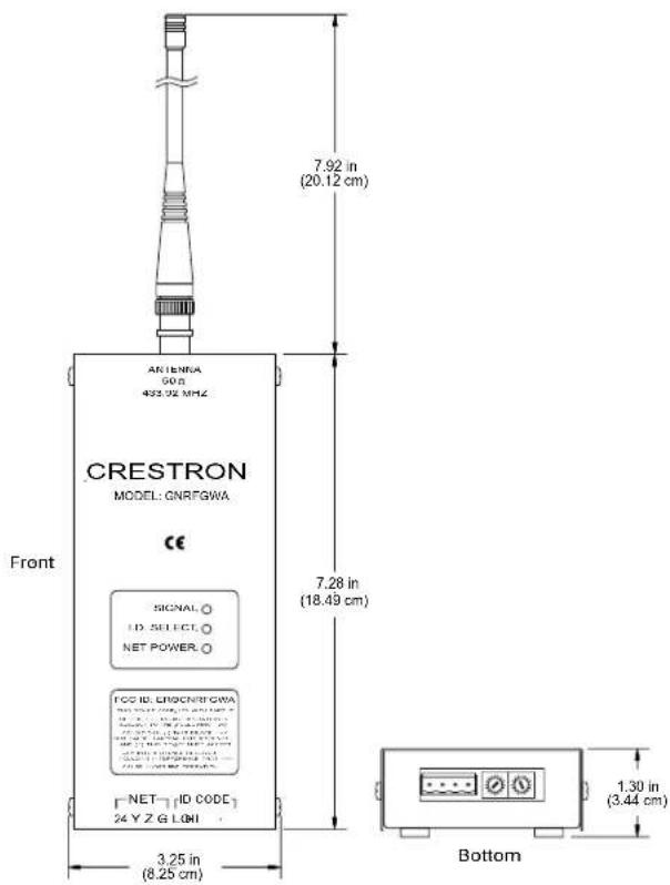
| Dimensions Width: 3.25 in (8.25 cm) | |
| Height: 7.28 in (18.49 cm) | |
| Depth: 1.3 in (3.44 cm) | |
| Antenna length: 7.92 in (20.12 cm) | |
| Weight 1.1 lb (0.5 kg) | |
1 The location of the CNRFGWA and the orientation of the antenna are important factors in the RF performance. With the unit located outside of any metal enclosures, the antenna is adjusted to achieve the best range. The range is dependent on its placement and the building in which it is used. The construction of the building, obstructions, and RF interference from other devices are factors determining the effective range of the unit.
2 The latest versions can be obtained from the Downloads | Software Updates section of the Crestron website (www.crestron.com). Refer to NOTE after last footnote.
3 Crestron 2-Series control systems include the AV2, AV2 with Card Cage, CP2, CP2E, PAC2, MC2W, MC2E, MP2, MP2E, PRO2, and RACK2.
4 Filenames for CNX and ST-CP update files have a UPZ extension. Files on the website may be .zip or self-extracting .exc files containing the .cuz or .upz file. To avoid program problems, make sure you are using the update file with the correct suffix letter (e.g., S, V, W, X).
NOTE: Crestron software and any files on the website are for Authorized Crestron dealers and Crestron Authorized Independent Programmers (CAIP) only. New users may be required to register to obtain access to certain areas of the site (including the FTP site).
Physical Description
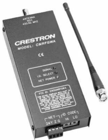
The CNRFGWA, shown on the next page, is housed in a black enclosure with labeling on the front panel. Three light-emitting diodes (LEDs) on the front of the unit indicate the unit's operating status. The RF antenna is attached via the BNC connector on the top of the unit; a four-pin connector is provided on the bottom panel for connection to other Cresnet devices. Two miniature rotary switches on the bottom panel are used to set the unit's network ID. Four rubber feet on the back of the unit prevent slippage when the unit is placed in its usual operating position.
Physical View of CNRFGWA Detail Views of CNRFGWA
CNRFGWA Port and Controls
The bottom panel of the CNRFGWA contains a Cresnet port and two miniature rotary switches. (Labeling for the connector and switches is on the front face of the unit.) Refer to the diagram on the previous page and descriptions that follow.
NET (FOUR-WIRE CRESNET)
This 4-pin connector is used to connect the CNRFGWA to other four-wire devices in the Cresnet system.
ID CODE (HI LO SWITCHES)
These two rotary switches are used to set the unit's network identity code. Refer to "Identity Code" on page 5 for details.
CNRFGWA Indicators
Three LEDs located on the front panel of the CNRFGWA indicate the unit's status. Refer to the descriptions on the next page.
SIGNAL
This red LED illuminates when the CNRFGWA receives a valid signal from a wireless touchpanel or remote.
I.D. SELECT
This red LED illuminates when communication with the Cresnet system and the CNRFGWA is established (the unit is polled on the network). Illumination indicates that the SIMPL Windows program currently loaded has a network device defined at the same Net ID code as the CNRFGWA.
NET POWER
This green LED illuminates when Cresnet power is supplied to the CNRFGWA.
Industry Compliance
As of the date of manufacture, this unit has been tested and found to comply with specifications for CE marking and standards per EMC and Radio Communications Compliance Labeling (N11785).


NOTE: This device complies with part 15 of the FCC rules. Operation is subject to the following two conditions: (1) this device may not cause harmful interference, and (2) this device must accept any interference received, including interference that may cause undesired operation.
NOTE: This equipment has been tested and found to comply with the limits for a Class B digital device, pursuant to part 15 of the FCC Rules. These limits are designed to provide reasonable protection against harmful interference in a residential installation. The equipment generates, uses and can radiate radio frequency energy and, if not installed and used in accordance with the instructions, may cause harmful interference to radio communications. However, there is no guarantee that interference will not occur in a particular installation. If this equipment does cause harmful interference to radio or television reception, which can be determined by turning the equipment off and on, the user is encouraged to try to correct the interference by one or more of the following measures:
■ Reorient or relocate the receiving antenna.
■ Increase the separation between the equipment and transceiver.
■ Connect the equipment into an outlet on a circuit different from that to which the transceiver is connected.
■ Consult the dealer or an experienced radio/TV technician for help.
Setup
Network Wiring
CAUTION: Use only Crestron power supplies for Crestron equipment. Failure to do so could cause equipment damage or void the Crestron warranty.
NOTE: When installing network wiring, refer to the latest revision of the wiring diagram(s) appropriate for your specific system configuration, available from the Downloads | Product Manuals | Wiring Diagrams section of the Crestron website (www.crestron.com).
When calculating the wire gauge for a network run, the length of the run and the power factor (power usage in watts) of each network unit must be taken into consideration. If multiple network units are to be daisy-chained, the power factors of each unit must be added to determine the power factor of the entire chain. The length of the run in feet and the power factor of the run (in watts) should then be used in the following resistance equation.
R lt; 4 0 , 0 0 0L × PF
Where: amp; R = Resistance (refer to table below). amp; L = Length of run (or chain) in feet. amp; PF = Power factor of entire run (or chain).
The required wire gauge should be chosen such that the resistance value is less than the value calculated in the resistance equation. Refer to the table after this paragraph.
Wire Gauge Values
| RESISTANCE (R) WIRE GAUGE | |
| 4 | 16 |
| 6 | 18 |
| 10 | 20 |
| 15 | 22 |
| 13 | Doubled CAT5 |
| 8.7 | Tripled CAT5 |
NOTE: All network wiring must consist of two twisted-pairs. One twisted pair is the +24V conductor and the GND conductor; the other twisted pair is the Y conductor and the Z conductor.
NOTE: When daisy-chaining Cresnet units, strip the ends of the wires carefully to avoid nicking the conductors. Twist together the ends of the wires that share a pin on the network connector, and tin the twisted connection. Apply solder only to the ends of the twisted wires. Avoid tinning too far up the wires or the end becomes brittle. Insert the tinned connection into the Cresnet connector and tighten the retaining screw. Repeat the procedure for the other three network conductors.
Identity Code
Every piece of equipment and user interface within the network requires a unique identity code (Net ID). These codes are two-digit hexadecimal numbers from 03 to
For a definition of Viewport, refer to the Note on page 8
FE. The Net ID of each unit must match an ID code specified in the SIMPL Windows program.
The Net ID of the CNRFGWA is factory set to 24. The Net IDs of multiple CNRFGWAs in the same system must all be unique. To set or change the Net ID of the CNRFGWA, make sure power to the unit is disconnected and complete the following steps.
- Locate the two rotary switches on the bottom of the unit. The left switch (HI) represents the most significant digit of the Net ID; the right switch (LO) represents the least significant digit of the Net ID. Each 16-position switch can be set to a value between 0 and F.
- Use a small screwdriver to rotate the arrow in the center of the two rotary switches. Set the arrow of the left switch to the Net ID's most significant digit (default is 2); set the arrow of the right switch to the Net IDs least significant digit (default is 4).
- Connect the CNRFGWA to the Cresnet system (verify that the software is running) and open the Crestron Viewport. Either launch the stand-alone version of Viewport, or start SIMPL Windows or VT Pro-e, and from the menu bar, select Tools | Viewport.
- From the Viewport menu, select Functions | Set Network ID. The software checks the baud rate and then opens the "Set Network ID" window.
- In the "Set Network ID" window, select the CNRFGWA from the Current Network Devices text window, and verify the Net ID code.
- In the "Set Network ID" window, click Close.
NOTE: The Net ID code may also be verified by selecting Diagnostic | Report Network Devices in the Viewport.
- Attach each CNRFGWA to be added to the Cresnet system individually and repeat this procedure as needed.
Hardware Hookup
Hookup of the CNRFGWA consists of connecting it to the Cresnet system via the network port on the bottom panel.
NOTE: Refer to "Network Wiring" on page 5 when making connections to the port labeled NET.
Programming Software
NOTE: Have a question or comment about Crestron software?
Answers to frequently asked questions (FAQs) can be viewed in the Online Help section of the Crestron website (www.crestron.com). To post your own question or view questions you have submitted to Crestron's True Blue Support, log in at http://www.crestron.com/accounts/login.asp. First-time users will need to establish a user account.
Earliest Version Software Requirements for the PC
NOTE: Crestron recommends that you use the latest software to take advantage of the most recently released features. The latest software is available from the Downloads | Software Updates section of the Crestron website (www.crestron.com).
The following are the earliest useable software version requirements for the PC:
- SIMPL Windows, any version. Requires SIMPL+ Cross Compiler version 1.1.
- Crestron Database version 16.0.0 or later. Required for SIMPL Windows.
- Crestron Viewport version 3.35 or later
Programming with SIMPL Windows
The CNRFGWA gateway provides one-way wireless RF communication between a Crestron wireless touchpanel or wireless remote device and a Crestron 2-Series or CNX control system.
Although the device itself is not programmable, you can create a program that includes a CNRFGWA using the Crestron programming tool SIMPL Windows.
SIMPL (Symbol Intensive Master Programming Language) is an easy-to-use programming language that is completely integrated and compatible with all Crestron system hardware. The objects that are used in SIMPL are called symbols. SIMPL Windows offers drag and drop functionality in a familiar Windows ® environment.
SIMPL Windows is Crestron's software for programming Crestron control systems. It provides a well-designed graphical environment with a number of workspaces (i.e., windows) in which a programmer can select, configure, program, test, and monitor a Crestron control system.
To create a program with a CNRFGWA, consult the operations and installation guide for any of the one-way wireless RF touchpanels or remote devices. The latest versions of these guides can be obtained from the Downloads | Product Manuals section of the Crestron website (www.crestron.com).
Example Program
The CNRFGWA is used with Crestron's wireless one-way RF remote devices and touchpanels such as the ST-1550C. An example program for the ST-1550C that includes the CNRFGWA is available from the Crestron FTP site (ftp.crestron.com/Examples). Search for ST-1550C_SIMPL_Windows_example_file.smw.
Uploading
Assuming a PC is properly connected to the entire system, Crestron programming software allows the programmer to upload programs and projects after their development to the system and network devices. However, there are times when the files for the program and projects are compiled and not uploaded. Instead, compiled files may be distributed from programmers to installers, from Crestron to dealers, etc. Even firmware upgrades are available from the Crestron website as new features are developed after product releases. In those instances, one has the option to upload via the programming software or to upload and upgrade via the Crestron Viewport.
NOTE: The Crestron Viewport is available as a pull-down command from SIMPL Windows and VT Pro-e (Tools | Viewport) or as a standalone utility. The Viewport utility accomplishes multiple system tasks, primarily via an RS-232 or TCP/IP connection between the control system and a PC. It is used to observe system processes, upload new operating systems and firmware, change system and network parameters, and communicate with network device consoles and touchpanels, among many other tasks. Viewport can also function as a terminal emulator for generic file transfer. All of these functions are accessed through the commands and options in the Viewport menus. Therefore, for its effectiveness as a support and diagnostic tool, the Crestron Viewport may be preferred over development tools when uploading programs and projects.
NOTE: Firmware for the CNRFGWA is not upgradable in the field.
Before attempting to upload, it is necessary to establish communications.
Communication Settings
NOTE: For laptops and other PCs without a built-in RS-232 port, Crestron recommends the use of PCMCIA cards, rather than USB-to-serial adapters. If a USB-to-serial adapter must be used, Crestron has tested the following devices with good results:
Belkin (large model) F5U103
I/O
Gear
GUC232A
Keyspan
USA-19QW
Other models, even from the same manufacturer, may not yield the same results.
The procedure in this section provides details for RS-232 communication between the PC and the control system. If TCP/IP communication is preferred, consult the latest version of the Crestron e-Control Reference Guide (Doc. 6052) or the respective Operations Guide for the control system. These documents are available from the Downloads | Product Manuals section of the Crestron website (www.crestron.com). Refer to the figure below for a typical connection diagram when uploading files.
Note: Use a standard DB9 male to female "straight-through" cable.
Typical Connection Diagram when Establishing Communication

CONTROL SYSTEM
- Open the Crestron Viewport.
Either launch the stand-alone version of Viewport, or start SIMPL
Windows and from the menu bar, select Tools | Viewport.
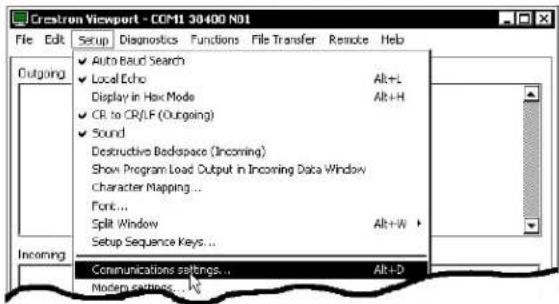
- Refer to the figure after this step. From the Viewport menu, select Setup | Communications settings (alternatively, press Alt+D) to open the "Port Settings" window.
Setup | Communications Settings Command
- Select RS-232 as the connection type. Verify that an available COM port (COM 1 is shown below) is selected, Verify that the baud rate is set to 38400 (PRO 2 default), the parity is None, the data bits is Eight, the stop bits is One, XON/XOFF is not selected, and RTS/CTS is selected. Click the OK button to save the settings and close the window.
"Port Settings" Window

NOTE: The parameters shown in the illustration above are the port settings for a 2-Series control system. Consult the Operations Guide for the control system being used for exact parameter selection.
- To verify communication, select Diagnostics | Establish Communications (Find Rack). This should display a window that gives the COM port and baud rate. If communication cannot be established, refer to the “Troubleshooting Communications” section in the respective Operations Guide for the control system.
A control system source file has the extension .smw. A compiled SIMPL Windows file has the extension .spz for a 2-Series control system, .bin for CNX generation, and .csz for CNX generation with SIMPL+.
Uploading a SIMPL Windows Program
The SIMPL Windows file can be uploaded to the control system using SIMPL Windows or via the Crestron Viewport.
Upload via SIMPL Windows
- Start SIMPL Windows.
- Select File | Open to view the "Open" window, navigate to the SIMPL Window file (.smw), and click Open.
- Select Project | Transfer Program.
Upload via Crestron Viewport
- Verify that the procedure for "Communication Settings" that begins on page 8 has been performed.
- As shown below, select File Transfer | Send Program (Alternatively, press Alt+P) from the Viewport menu.
File transfer | Send Program Command

- The "Send Program" window appears as shown after this step. Click Browse, locate the completed file (.spz for PRO2) and click Open. This displays the program's header information and enables one or both of the What to Send check boxes. If the program does not contain any SIMPL+ modules, only the SIMPL Program check box is enabled. If it does contain SIMPL+ modules, then the SIMPL+ Program(s) check box will also be enabled. Select one or both check boxes and then click Send Program to begin the transfer.
NOTE: Refer to the respective Operations Guide for control system details about the other fields in the "Send Program" window.
"Send Program" Window
![Send Program Current Program: **Unknown** System Name: division_of_contning_education Compiled On: 10.00/2002.9:25 AM Compiler Revision: 2.00.17 New Program: C:\backup\crnfgwa.spz Browse: What to Send: ✓ SIMPL Program □ SIMPL+Program[s] Transfer To: ● Internal Flash ○ Compact Flash Send Program Make Permanent Check Program □ Retrieve Program from Control System before overwriting Close Clear History](/content/2026/05/991420/images/5e238d5bf6ad001e49516d9fc86fa6753a3a5411155ccd609b90ea55d0d6332f.jpg)
- To verify that the program has been transferred successfully, select Diagnostics | Report Program Information. This should display a window that provides details about the current program loaded into the control system.
Problem Solving
Troubleshooting
The table below provides corrective action for possible trouble situations. If further assistance is required, please contact a Crestron customer service representative.
CNRFGWA Troubleshooting
| TROUBLE | POSSIBLE CAUSE(S) | CORRECTIVE ACTION |
| NET POWER LED does not illuminate. | Incorrect power supply. Use a Crestron power supply with sufficient power for the network. | |
| CNRFGWA is not receiving power. | Verify that network power is supplied to the unit. | |
| SIGNAL LED does not illuminate when wireless transmitter sends an RF signal. | There is no battery in the transmitter or the battery is dead. | Verify that a charged battery is in the transmitter and SIGNAL LED illuminates. |
| Hand-held transmitter is in sleep mode. | Press and hold any button on the transmitter until unit transmits. Verify SIGNAL LED illuminates | |
| I.D. SELECT LED does not illuminate. | CNRFGWA Net ID is not set to match the Net ID of the SIMPL program. | Open Viewport and press F4 to poll the network. Verify that the Net ID for the CNRFGWA is properly set to match the SIMPL program. |
| Net ID setting changes after CNRFGWA powered up. | Power down the CNRFGWA, then power up to reset the Net ID. | |
| CNRFGWA does not report Net ID when polling the network through Viewport. Other devices are reported. | Network wiring incorrect. | Check network cabling for solid connections and correct pinouts. |
| Unit is damaged. Contact | Customer Service. Refer to "Further Inquiries" in this guide. | |
| I.D. SELECT LED is on, but unit does not provide control. | Unit is not communicating on the network. | Check network cabling for solid connections and correct pinouts. |
| CNRFGWA Net ID not unique. Two or more units share same Net ID. | Verify that each Net ID is used only once. | |
| Intermittent response from CNRFGWA during transmission. | Refer to causes when LEDs do not illuminate. | Refer to corrective action when LEDs do not illuminate |
| CNRFGWA is in vicinity of metal. | Verify that large amount of metal is not in vicinity of transmission. | |
| Transmitter is near maximum range. | Move closer or add another CNRFGWA to increase coverage. | |
Further Inquiries
If, after reviewing this Operations Guide, you cannot locate specific information or have questions, please take advantage of Crestron's award winning customer service team by calling:
- In the US and Canada, call Crestron's corporate headquarters at 1-888-CRESTRON [1-888-273-7876].
• In Europe, call Crestron International at +32-15-50-99-50.
• In Asia, call Crestron Asia at +852-2341-2016.
• In Latin America, call Crestron Latin America at +5255-5093-2160. - In Australia and New Zealand, call Crestron Pacific at +613-9480-2999.
You can also log onto the online help section of the Crestron website (www.crestron.com) to ask questions about Crestron products. First-time users will need to establish a user account to fully benefit from all available features.
Future Updates
As Crestron improves functions, adds new features, and extends the capabilities of the CNRFGWA, additional information and programming examples may be made available as manual updates. These updates are solely electronic and serve as intermediary supplements prior to the release of a complete technical documentation revision.
Check the Crestron website (www.crestron.com) periodically for manual update availability and its relevance. Updates are available from the Download | Product Manuals section and are identified as an “Addendum” in the Download column.
Appendix: Optimum RF Reception Guidelines
Many factors can affect the reliability of RF communication between an RF touchpanel or remote device and an RF gateway. While an effort has been made to determine operating specifications, some specifications are not constant. RF Communication can be limited by several factors including but not limited to EMI (electromagnetic interference), intervening objects, antenna orientation, and receiver placement. To obtain maximum reliability and performance, some basic rules for installing RF receivers are listed below.
Minimize Interference
RF reception range can be hindered by spurious EMI noise that may interfere with or mask the desired frequency thereby reducing useable range. EMI is generated by any electrical device at various RF noise levels depending on the device. Sources of EMI include computers, video equipment, digital processors, lighting dimmers, lighting ballasts, motors or any large AC source. Every effort should be made to separate any RF transmitter/receiver from these sources of RF noise including Audio Visual equipment in racks. If a gateway must be installed in an equipment rack, make sure you have ample separation between the equipment and the gateway.
Gateway Placement
Optimum reception for any RF gateway is obtained by installing the gateway in an open area or shelf with a clear line of sight (no obstructions between gateway and touchpanel or wireless remote). Crestron recommends placing the gateway at least five to six feet high for best results. Avoid placing gateways or touchpanels/remotes at a low height or on the ground. Placing RF equipment near metal objects, walls, corners or metal enclosures will compromise RF propagation and reception. Try to avoid installing gateways in equipment racks, service rooms or electrical closets. For best results, Crestron recommends that the gateway be placed in the same room that the touchpanel or remote is located.
Antenna Orientation
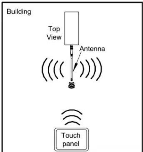
The antenna orientation of the Crestron gateway has considerable effect on range and reliability. Optimum performance is obtained by setting the gateway horizontally (antenna parallel to the ground) at right angles to the touchpanel. When absolutely necessary, two alternate orientations are possible—each will be less effective than the horizontal orientation:
■ Point the antenna vertically
- Point the antenna toward the wireless touchpanel/remote.
Never point the antenna downward. This will decrease range and reliability. Refer to illustrations on the next page for examples of the different antenna orientations.
NOTE: RF propagation is best from the sides of the antenna.
Horizontal Orientation

Vertical Orientation

Horizontal, Toward Touchpanel
Return and Warranty Policies
Merchandise Returns / Repair Service
-
No merchandise may be returned for credit, exchange, or service without prior authorization from CRESTRON. To obtain warranty service for CRESTRON products, contact the factory and request an RMA (Return Merchandise Authorization) number. Enclose a note specifying the nature of the problem, name and phone number of contact person, RMA number, and return address.
-
Products may be returned for credit, exchange, or service with a CRESTRON Return Merchandise Authorization (RMA) number. Authorized returns must be shipped freight prepaid to CRESTRON, 6 Volvo Drive, Rockleigh N.J., or its authorized subsidiaries, with RMA number clearly marked on the outside of all cartons. Shipments arriving freight collect or without an RMA number shall be subject to refusal. CRESTRON reserves the right in its sole and absolute discretion to charge a 15% restocking fee, plus shipping costs, on any products returned with an RMA.
-
Return freight charges following repair of items under warranty shall be paid by CRESTRON, shipping by standard ground carrier. In the event repairs are found to be non-warranty, return freight costs shall be paid by the purchaser.
CRESTRON Limited Warranty
CRESTRON ELECTRONICS, Inc. warrants its products to be free from manufacturing defects in materials and workmanship under normal use for a period of three (3) years from the date of purchase from CRESTRON, with the following exceptions: disk drives and any other moving or rotating mechanical parts, pan/tilt heads and power supplies are covered for a period of one (1) year; touchscreen display and overlay components are covered for 90 days; batteries and incandescent lamps are not covered.
This warranty extends to products purchased directly from CRESTRON or an authorized CRESTRON dealer. Purchasers should inquire of the dealer regarding the nature and extent of the dealer's warranty, if any.
CRESTRON shall not be liable to honor the terms of this warranty if the product has been used in any application other than that for which it was intended, or if it has been subjected to misuse, accidental damage, modification, or improper installation procedures. Furthermore, this warranty does not cover any product that has had the serial number altered, defaced, or removed.
This warranty shall be the sole and exclusive remedy to the original purchaser. In no event shall CRESTRON be liable for incidental or consequential damages of any kind (property or economic damages inclusive) arising from the sale or use of this equipment. CRESTRON is not liable for any claim made by a third party or made by the purchaser for a third party.
CRESTRON shall, at its option, repair or replace any product found defective, without charge for parts or labor. Repaired or replaced equipment and parts supplied under this warranty shall be covered only by the unexpired portion of the warranty.
Except as expressly set forth in this warranty, CRESTRON makes no other warranties, expressed or implied, nor authorizes any other party to offer any warranty, including any implied warranties of merchantability or fitness for a particular purpose. Any implied warranties that may be imposed by law are limited to the terms of this limited warranty. This warranty statement suprecedes all previous warranties.
Trademark Information
All brand names, product names, and trademarks are the sole property of their respective owners. Windows is a registered trademark of Microsoft Corporation. Windows95/98/Me/XP and WindowsNT/2000 are trademarks of Microsoft Corporation.

CRESTRON
Crestron Electronics, Inc. Operations Guide - DOC. 8086A
15 Volvo Drive Rockleigh, NJ 07647 10.03
Tel: 888.CRESTRON
Fax: 201.767.7576 Specifications subject to
www.crestron.com change without notice.
- Wireless RF Receiver
- Operations Guide
- CRESTRON
- Contents
- Wireless RF Receiver: CNRFGWA 1
- Wireless RF Receiver: CNRFGWA
- Introduction
- Functions and Features
- Functional Summary
- Specifications
- Physical Description
- CNRFGWA Port and Controls
- NET (FOUR-WIRE CRESNET)
- ID CODE (HI LO SWITCHES)
- CNRFGWA Indicators
- SIGNAL
- I.D. SELECT
- NET POWER
- Industry Compliance
- Setup
- Network Wiring
- Identity Code
- Hardware Hookup
- Programming Software
- Earliest Version Software Requirements for the PC
- Programming with SIMPL Windows
- Uploading
- Communication Settings
- Uploading a SIMPL Windows Program
- Upload via SIMPL Windows
- Upload via Crestron Viewport
- Problem Solving
- Troubleshooting
- Further Inquiries
- Future Updates
- Appendix: Optimum RF Reception Guidelines
- Minimize Interference
- Gateway Placement
- Antenna Orientation
- Return and Warranty Policies
- Merchandise Returns / Repair Service
- CRESTRON Limited Warranty
- Trademark Information
Brand : Crestron
Model : CNRFGWA-418
Category : Récepteur radio sans fil