
ARC-1203-2I - Controller Areca - Free user manual and instructions
Find the device manual for free ARC-1203-2I Areca in PDF.


| Product Type | Internal SAS/SATA RAID Controller |
| Brand | Areca |
| Model | ARC-1203-2I |
| Interface | PCI Express 2.0 x8 |
| Supported Devices | SAS and SATA hard drives and SSDs |
| Number of Internal Ports | 2 (mini-SAS, 8 total drives via expanders) |
| RAID Levels | 0, 1, 10, 3, 5, 6, 30, 50, 60, Single Disk, JBOD |
| Cache Memory | 512 MB DDR2-800 with ECC protection |
| Data Transfer Rate | Up to 3 Gbps per port (SAS 3.0) |
| Form Factor | Low-profile MD2 (6.6 x 2.5 inches) |
| Weight | Approximately 200 g |
| Power Consumption | Typical 15 W |
| Key Features | Hardware RAID, online capacity expansion, RAID level migration, hot-swap support, S.M.A.R.T. monitoring, web-based management |
| Operating Systems Supported | Windows, Linux, FreeBSD, VMware, macOS |
| Cache Backup | Optional battery backup unit (BBU) or flash backup module |
| Cooling | Passive heatsink (requires active airflow in chassis) |
| Management | Web GUI, SNMP, CLI, and LCD module (optional) |
| Maintenance | Firmware updates via web interface; clean with dry cloth |
| Safety | CE, FCC, RoHS compliant; standard precautions for ESD |
| Warranty | 3 years limited hardware warranty |
Frequently Asked Questions - ARC-1203-2I Areca
User questions about ARC-1203-2I Areca
0 question about this device. Answer the ones you know or ask your own.
Ask a new question about this device
Download the instructions for your Controller in PDF format for free! Find your manual ARC-1203-2I - Areca and take your electronic device back in hand. On this page are published all the documents necessary for the use of your device. ARC-1203-2I by Areca.
USER MANUAL ARC-1203-2I Areca
(PCIe 2.0 to 6Gb/s SATA RAID Controllers)
Copyright and Trademarks
The information regarding products in this manual is subject to change without prior notice and does not represent a commitment on the part of the vendor, who assumes no liability or responsibility for any errors that may appear in this manual. All brands and trademarks are the properties of their respective owners. This manual contains materials protected under International Copyright Conventions. All rights reserved. No part of this manual may be reproduced in any form or by any means, electronic or mechanical, including photocopying, without the written permission of the manufacturer and the author.
FCC Statement
This equipment has been tested and found to comply with the limits for a Class B digital device, pursuant to part 15 of the FCC Rules. These limits are designed to provide reasonable protection against interference in a residential installation. This equipment generates, uses, and can radiate radio frequency energy and, if not installed and used in accordance with the instructions, may cause harmful interference to radio communications. However, there is no guarantee that interference will not occur in a particular installation.
Manufacturer's Declaration for CE Certification
We confirm ARC-1203-2I has been tested and found compliant with the requirements in the council directive relating to the EMC Directive 2004/108/EC. Regarding to the electromagnetic compatibility, the following standards were applied:
EN 55022: 2006, Class B
EN 61000-3-2: 2006
EN 61000-3-3: 1995+A1: 2001+A2: 2005
EN 55024:1998+A1:2001=A2:2003
IEC61000-4-2: 2001
IEC61000-4-3: 2006
IEC61000-4-4: 2004
IEC61000-4-5: 2005
IEC61000-4-6: 2006
IEC61000-4-8: 2001
IEC61000-4-11: 2004
Contents
1. Introduction......10
1.1 Overview ...... 10
1.2 Features 12
2. Hardware Installation .... 14
2.1 Before You First Installing.... 14
2.2 Board Layout....14
2.3 Installation....18
2.4 Summary of the installation....26
3. McBIOS RAID Manager 29
3.1 Starting the McBIOS RAID Manager....29
3.2 McBIOS RAID manager 30
3.3 Configuring Raid Sets and Volume Sets 31
3.4 Designating Drives as Hot Spares 31
3.5 Using Quick Volume /Raid Setup Configuration 32
3.6 Using Raid Set/Volume Set Function Method 33
3.7 Main Menu 35
3.7.1 Quick Volume/Raid Setup 36
3.7.2 Raid Set Function 40
3.7.2.1 Create Raid Set 41
3.7.2.2 Delete Raid Set 42
3.7.2.3 Expand Raid Set 43
3.7.2.4 Offline Raid Set 44
3.7.2.5 Activate Incomplete Raid Set....45
3.7.2.6 Create Hot Spare 46
3.7.2.7 Delete Hot Spare 46
3.7.2.8 Rescue Raid Set 47
3.7.2.9 Raid Set Information 48
3.7.3 Volume Set Function 48
3.7.3.1 Create Volume Set (0/1)......49
• Volume Name 51
- Raid Level 52
- Capacity 52
- Stripe Size .... 54
- SCSI ID 55
• SCSI LUN....55
- Cache Mode .... 56
- Write Protect .... 56
- Tag Queuing 57
3.7.3.2 Delete Volume Set 57
3.7.3.3 Modify Volume Set....58
3.7.3.3.1 Volume Growth....58
3.7.3.3.2 Volume Set Migration 59
3.7.3.4 Check Volume Set....60
3.7.3.5 Stop Volume Set Check 60
3.7.3.6 Display Volume Set Info. 60
3.7.4 Physical Drives....61
3.7.4.1 View Drive Information 61
3.7.4.2 Create Pass-Through Disk 62
3.7.4.3 Modify Pass-Through Disk 63
3.7.4.4 Delete Pass-Through Disk 63
3.7.4.5 Set Disk To Be Failed 64
3.7.4.6 Activate Failed Disk....64
3.7.4.7 Identify Selected Drive 65
3.7.4.8 Identify Enclosure....65
3.7.5 Raid System Function 66
3.7.5.1 Mute The Alert Beeper....66
3.7.5.2 Alert Beeper Setting....67
3.7.5.3 Change Password 67
3.7.5.4 JBOD/RAID Function 68
3.7.5.5 Background Task Priority 68
3.7.5.6 SATA NCQ Support....69
3.7.5.7 HDD Read Ahead Cache....70
3.7.5.8 Volume Data Read Ahead....70
3.7.5.9 Empty HDD Slot LED 71
3.7.5.10 Auto Activate Raid Set 72
3.7.5.11 Disk Write Cache Mode 72
3.7.5.12 Write Same Support....73
3.7.5.13 Capacity Truncation....73
3.7.6 More System Functions 74
3.7.6.1 Smart Option For HDD.... 75
3.7.6.2 Smart Polling Interval.... 75
3.7.6.3 Hot Plugged Disk For Rebuilding 76
3.7.7 HDD Power Management 77
3.7.7.1 Stagger Power On....78
3.7.7.2 Time To Hdd Low Power Idle 79
3.7.7.3 Time To Low RPM Mode 79
3.7.7.4 Time To Spin Down Idle Hdd 80
3.7.8 Alert By Mail Config 80
3.7.9 View System Events 81
3.7.10 Clear Events Buffer 81
3.7.11 Hardware Monitor....82
3.7.12 System Information 82
4. Driver Installation....83
4.1 Creating the Driver Disk....83
4.2 Driver Installation for Windows 84
4.2.1 Installing Windows on a RAID Volume 84
4.2.2 Installing Controller on an Existing Windows 86
4.2.3 Uninstall controller from Windows....87
4.3 Driver Installation for Linux 88
4.4 Driver Installation for FreeBSD....88
4.5 Driver Installation for Solaris 89
4.6 Driver Installation for Mac X 89
4.6.1 Installation Procedures....90
4.6.2 Making Volume Sets Available to Mac OS X 92
5. ArcHTTP Proxy Server Installation 94
5.1 For Windows.... 95
5.2 For Linux 96
5.3 For FreeBSD 98
5.4 For Solaris 10 98
5.5 For Mac OS X....99
5.6 ArcHTTP Configuration 99
6. Web Browser-based Configuration 104
6.1 Start-up McRAID Storage Manager 104
- Start-up from Windows/Mac Local Administration ...... 105
- Start-up from Local Administration 105
6.2 McRAID Storage Manager....106
6.3 Main Menu 107
6.4 Quick Function....107
6.5 Raid Set Functions 108
6.5.1 Create Raid Set 108
6.5.2 Delete Raid Set 109
6.5.3 Expand Raid Set.... 109
6.5.4 Offline Raid Set 110
6.5.5 Rename Raid Set.... 111
6.5.6 Activate Incomplete Raid Set 111
6.5.7 Create Hot Spare 112
6.5.8 Delete Hot Spare.... 113
6.5.9 Rescue Raid Set 113
6.6 Volume Set Functions 114
6.6.1 Create Volume Set (0/1) 114
6.6.2 Delete Volume Set.... 117
6.6.3 Modify Volume Set.... 118
6.6.3.1 Volume Growth 118
6.6.3.2 Volume Set Migration 119
6.6.4 Check Volume Set 120
6.6.5 Stop Volume Set Check 120
6.7 Physical Drive 121
6.7.1 Create Pass-Through Disk.... 121
6.7.2 Modify Pass-Through Disk 121
6.7.3 Delete Pass-Through Disk 122
6.7.4 Clone Disk....123
6.7.4.1 Clone And Replace 124
6.7.4.2 Clone Only 124
6.7.5 Abort Cloning.... 124
6.7.6 Set Disk To Be Failed 124
6.7.7 Activate Failed Disk 125
6.7.8 Identify Enclosure 125
6.7.9 Identify Drive 126
6.8 System Controls 127
6.8.1 System Config 127
- System Beeper Setting 127
- JBOD/RAID Configuration 127
• SATA NCQ Support 128
- HDD Read Ahead Cache 128
• Volume Data Read Ahead 128
• Empty HDD Slot LED 128
- Max Command Length 128
• Auto Activate Incomplete Raid 129
- Disk Write Cache Mode 129
- Write Same For Initialization....129
- Hot Plugged Disk For Rebuilding 129
- Disk Capacity Truncation Mode....130
- Smart Option For HDD 130
- Smart Polling Interval 131
6.8.2 Advanced Configuration....131
- TLER Setting 131
- Timeout Setting 132
• Number of Retries 132
- Buffer Threshold 132
- Amount of Read Ahead 132
• Number of AV Stream....133
- Optimize AV Recording....133
- Read Performance Margin....134
- Write Performance Margin .... 134
- Read And Discard Parity Data 134
- BIOS Selection.... 134
6.8.3 HDD Power Management....135
- Stagger Power On Control 135
- Time To Hdd Low Power Idle 136
- Time To Spin Down Idle HDD 136
- SATA Power Up In Standby 136
6.8.4 View Events/Mute Beeper 136
6.8.5 Generate Test Event 137
6.8.6 Clear Events Buffer.... 137
6.8.7 Modify Password 138
6.8.8 Update Firmware 139
6.9 Information....139
6.9.1 Raid Set Hierarchy....139
6.9.2 System Information 140
6.9.3 Hardware Monitor.... 140
Appendix A 141
Upgrading Flash ROM Update Process.... 141
A-1 Overview 141
A-2 Upgrading Firmware Through McRAID Storage Manager ... 142
A-3 Upgrading Firmware Through nflash DOS Utility 143
A-4 Upgrading Firmware Through CLI 144
Appendix B 145
Battery Backup Module (ARC-6120BA-T121-12G)....145
Appendix C 149
SNMP Operation & Installation 149
C-1 Overview 149
C-2 SNMP Definition.... 149
C-3 SNMP Installation 150
C-3-1 Using ArcHTTP.... 151
C-3-2 Using In-band PCIe + SNMP extension agent Installation 152
C-3-3 SNMP Extension Agent Installation 153
C-3-3-1 Windows.... 154
C-3-3-2 Linux 157
C-3-3-3 FreeBSD 157
Appendix D....159
Appendix E 163
RAID Concept 163
RAID Set 163
Volume Set.... 163
Ease of Use Features.... 164
- Foreground Availability/Background Initialization .... 164
• Online Array Roaming 164
• Online Capacity Expansion.... 164
• Online RAID Level and Stripe Size Migration ..... 166
• Online Volume Expansion 167
High Availability 167
- Global/Local Hot Spares 167
• Hot-Swap Disk Drive Support.... 168
• Auto Declare Hot-Spare 168 - Auto Rebuilding 169
- Adjustable Rebuild Priority....169
High Reliability 170
- Hard Drive Failure Prediction....170
• Auto Reassign Sector 170
Data Protection 171
- Battery Backup 171
- Recovery ROM 172
Appendix F 173
Understanding RAID 173
RAID 0....173
RAID 1....174
JBOD 175
Single Disk (Pass-Through Disk) 175
Summary of RAID Levels 175
1. Introduction
This section presents a brief overview of the 6Gb/s SATA RAID controller, ARC-1203-2I. (PCIe 2.0 to 6Gb/s SATA RAID controller)
1.1 Overview
The Areca ARC-1203-2I SATA RAID host adapter is a PCIe 2.0 x1 bus to 6Gb/s SATA disk array host adapter. It provides two SATA III ports on a single controller. It is used the same RAID kernel of its field-proven 6Gb/s, and 12Gb/s SAS RAID controller and uses the same drivers and management tools to help keep implementation and maintenance costs low. When properly configured, the SATA RAID adapter can provide a high degree of performance and fault tolerance with data mirroring for maximum protection. The ARC-1203-2I is the industry's most compelling 2-port 6Gb/s SATA RAID solution which economically delivers fullfeatured true hardware RAID to desktop and workstations as well as entry-level servers.
Unparalleled Performance
The SATA RAID controllers raise the standard to higher performance levels with several enhancements including high-performance 1066MHz storage processor, a new DDR3-1066 memory architecture, and 6Gb/s SATA III ports in a high performance PCIe 2.0 x1 bus interconnection. The ARC-1203-2I default supports on-board 512MB DDR3-1066 SDRAM memory. The test result is against overall performance compared to other standard SATA host adapter.
Unsurpassed Data Availability
With Areca entry-level RAID controllers incorporate onboard storage processors to deliver true hardware RAID. Hardware RAID cards have their own local RAID processor onboard, plus dedicated onboard cache for full hardware offloading of RAID-processing functions. The ability of hardware RAID controllers to rebuild an array in the event of a drive failure is superior to what software RAID controllers offer.
The ARC-1203-2I RAID adapters can provide RAID levels 0, 1, Single Disk and JBOD RAID for maximum configuration flexibility. Its high data availability and protection derives from Areca Technology's advanced features: Online RAID Capacity Expansion, Array Roaming, Online RAID Level / Stripe Size Migration, Global Online Spare, Automatic Drive Failure Detection, Automatic Failed Drive Rebuilding, Disk Hot-Swap, Online Background Rebuilding, Instant Availability/Background Initialization and Auto Reassign Sector.
During the adapter firmware upgrade flash process, it is possible for a problem to occur resulting in corruption of the controller firmware. With our redundant flash image feature the adapter will revert back to the last known version of firmware and continue operating. This reduces the risk of system failure due to firmware crash. The optional battery backup module provides power to the cache if it contains data not yet written to the drives when power is lost.
Maximum Interoperability
The Areca ARC-1203-2I is a half length low profile SATA III RAID controller. It supports broad operating system including Windows 10/8/Server 2012(R2)/7/2008(R2)/Vista/Server 2003/XP, RedHat Linux, SuSE Linux, FreeBSD, Solaris, Mac OS and more, along with key system monitor-ing features such as SMTP, and SNMP function.
Easy RAID Management
The BIOS contains an embedded McBIOS RAID manager that can access via hot key at BIOS boot-up screen. This pre-boot RAID manager can use to simplify the setup and management of RAID adapter. The adapter firmware also contains and browser-based McRAID storage manager that can access through the ArcHTTP Proxy Server. The McRAID manager allows local and remote to create and modify RAID set, volume set, and monitor RAID status from standard web browser. API software components and CLI also support for the RAID manager. The Single Admin Portal (ArcSAP) quick manager can support one application to scan multiple RAID units in the local and remote for easy installation, configuration and operation.
1.2 Features
Controller Architecture
- ARM_based 1066MHz storage I/O processor
- 512MB on-board DDR3-1066 SDRAM with ECC protection
- PCIe 2.0 x1 bus
- Support up to 2 x 6Gb/s SATA HDDs/SSD
- Write-through or write-back cache support
- Multi-adapter support for large storage requirements
• BIOS boot support for greater fault tolerance - BIOS PnP (plug and play) and BBS (BIOS boot specification) support
- NVRAM for RAID event & transaction log
- Boot support for the uEFI host BIOS
- Redundant flash image for controller availability
- RoHS compliant
- Battery backup module (BBM) ready (optional)
- Disk activity/fault LED on bracket
RAID Features
- RAID level 0, 1, Single Disk and JBOD
- Configurable stripe size up to 1024KB
- Multiple RAID selection
• Online array roaming
• Online RAID level/stripe size migration - Online capacity expansion and RAID level migration simultaneously
- Instant availability and background initialization
• Automatic drive insertion/removal detection and rebuilding - Greater than 2TB capacity per disk drive support
- SED (self-encrypting drives) function support
- Support intelligent power management to save energy and extend service life
- Support for native 4K and 512 byte sector SATA devices
- Support HDD firmware update
Monitors/Notification
- System status indication through global HDD activity/fault connector, individual fault connector, LCD/serial bus connector and alarm buzzer
- SMTP support for email notification
• SNMP support for remote manager
RAID Management
- Field-upgradeable firmware in flash ROM
In-Band Manager
- Hot key "boot-up" McBIOS RAID manager via M/B BIOS
- Web browser-based McRAID storage manager via ArcHTTP proxy server for all operating systems
- Support Command Line Interface (CLI)
- API library for customer to write monitor utility
- Single Admin Portal (SAP) monitor utility
Out-of-Band Manager
- Push Button and LCD display panel (optional)
Operating System
• Windows 10/8/2012/7/2008/Vista/XP/2003
- Linux
- FreeBSD
- VMware
- Solaris 10/11 x86/x86_64
• Mac OS X 10.5 / macOS 10.12 or higher
| 6Gb/s SATA RAID controllers | |
| Model name ARC-1203-2i | |
| I/O Processor ARM_based 1066MHz storage I/O processor | |
| Form Factor (H x L) Low Profile: 64.4 x 134 mm | |
| Host Bus Type PCIe 2.0 x1 bus | |
| Driver Connector 2 x SATA III | |
| Drive Support Up to 2 x 6Gb/s SATA HDDs/SSD | |
| RAID Level 0,1, Single Disk and JBOD | |
| On-Board Cache 512MB on-board DDR3-1066 SDRAM with ECC protection | |
| Management Port In-Band: PCIe / Out-of-Band: Push Button and LCD |
Note:
Low-profile bracket has included on the low profile board shipping package.
2. Hardware Installation
This section describes the procedures for installing the 6Gb/s SATA RAID controllers.
2.1 Before You First Installing
Thanks for purchasing the 6Gb/s SATA RAID controller as your RAID data storage subsystem. This user manual gives simple step-by-step instructions for installing and configuring the 6Gb/s SATA RAID controller. To ensure personal safety and to protect your equipment and data, reading the following information package list carefully before you begin installing.
Package Contents
If your package is missing any of the items listed below, contact your local dealers before you install. (Disk drives and disk mounting brackets are not included)
- 1 x ARC-1203-2I RAID controller in an ESD-protective bag
- 1 x Installation CD – containing driver, relative software, an electronic version of this manual and other related manual
- 2 x SATA interface cables
- 1 x Quick start guide
- 1 x Low-profile bracket
2.2 Board Layout
The RAID controllers can support a family SATA interface included 2 internal ports with 6Gb/s capability. This section provides the board layout and connector/jumper for the 6Gb/s SATA RAID controller.

| Connector Type Description | ||
| 1. (J1) Battery | Backup Module Connector 14-pin wafer connector | |
| 2. (J2) Global | Fault/Activity LED Header 4-pin header | |
| 3. (J3) Individual | dual Fault/Activity LED Header 4-pin header | |
| 4. (J4) I | 2C/LCD Connector 7-pin header | |
| 5. (J5) Manufacture | Purpose Port 14-pin header | |
| 6. (SCN1) SATA | Port 1 (CH2) SATA III | |
| 7. (SCN2) SATA | Port 0 (CH1) SATA III | |
| 8. (D3) Fault | Activity LED (for CH1) Bi-color DIP | |
| 9. (D4) Fault | Activity LED (for CH2) Bi-color DIP | |
Table 2-1, ARC-1203-2i connectors
Tools Required
An ESD grounding strap or mat is required. Also required are standard hand tools to open your system's case.
System Requirement
The 6Gb/s SATA RAID controller can be installed in an universal PCIe slot and requires a motherboard that:
ARC-1203-2i 6Gb/s SATA RAID controller requires:
- Comply with the PCIe 2.0 x1 lanes
- Backward-compatible with PCIe 1.0
The SATA RAID controller may be connected to up to 2 cables. Optional cables are required to connect any drive activity LEDs and fault LEDs on the enclosure to the SATA RAID controller.
Installation Tools
The following items may be needed to assist with installing the 6Gb/s SATA RAID controller into an available PCIe expansion slot.
- Small screwdriver
- Host system hardware manuals and manuals for the disk or enclosure being installed.
Personal Safety Instructions
Use the following safety instructions to help you protect your computer system from potential damage and to ensure your own personal safety.
- Always wear a grounding strap or work on an ESD-protective mat.
- Before opening the system cover, turn off power switches and unplug the power cords. Do not reconnect the power cords until you have replaced the covers.
Electrostatic Discharge
Static electricity can cause serious damage to the electronic components on this 6Gb/s SATA RAID controller. To avoid damage caused by electrostatic discharge, observe the following precautions:
- Do not remove the 6Gb/s SATA RAID controller from its anti-static packaging until you are ready to install it into a computer case.
- Handle the 6Gb/s SATA RAID controller by its edges or by the metal mounting brackets at its each end.
- Before you handle the 6Gb/s SATA RAID controller in any way, touch a grounded, anti-static surface, such as an unpainted portion of the system chassis, for a few seconds to discharge any built-up static electricity.
Warning:
High voltages may be found inside computer equipment. Before installing any of the hardware in this package or removing the protective covers of any computer equipment, turn off power switches and disconnect power cords. Do not reconnect the power cords until you have replaced the covers.
2.3 Installation
Use the following instructions below to install a PCIe 2.0 6Gb/s SATA RAID controller.
Step 1. Unpack
Unpack and remove the PCIe 2.0 6Gb/s SATA RAID controller from the package. Inspect it carefully, if anything is missing or damaged, contact your local dealer.
Step 2. Power PC/Server Off
Turn off computer and remove the AC power cord. Remove the system's cover. For the instructions, please see the computer system documentation.
Step 3. Install the PCIe 6Gb/s SATA RAID Cards
To install the 6Gb/s SATA RAID controller, remove the mounting screw and existing bracket from the rear panel behind the selected PCIe 2.0 slot. Align the gold-fingered edge on the card with the selected PCIe 2.0 slot. Press down gently but firmly to ensure that the card is properly seated in the slot, as shown on Figure 2-2. Then, screw the bracket into the computer chassis.
Figure 2-2, Insert into a PCIe slot

Step 4. Mount the Drives
You can connect the SATA drives to the controller through direct cable. In the direct connection, SATA drives are directly connected to 6Gb/s SATA RAID controller port with SATA cables. The 6Gb/s SATA RAID controller can support up to 2 ports. Remove the front bezel from the computer chassis and install the cages or SATA drives in the computer chassis. Loading drives to the drive tray if cages are installed. Be sure that the power is connected to the individual drives.
Step 5. Connect the SATA Cable
ARC-1203-2I controller has two SATA internal connectors. If you have not yet connected your SATA cables, use the cables included with your kit to connect the controller to the SATA hard drives. The cable connectors are all identical, so it does not matter which end you connect to your controller, SATA hard drive, or cage back-plane SATA connector.
Figure 2-3, SATA Cable

Note:
The SATA cable connectors must match your HDD cage. For example: Channel 1 of RAID controller connects to channel 1 of HDD cage, channel 2 of RAID controller connects to channel 2 of HDD cage, and follow this rule.
Step 6. Install the LED Cable (Optional)
The 6Gb/s SATA controller provides LED cable header to support the fault/activity status. The global indicator connector is used by the server/desktop system global indicator LED.
The following electronics schematic is the 6Gb/s SATA RAID controller logical of fault/activity header. The signal from EPLD CTL output pin is cathode (-) side.
The following diagrams and descriptions describe each type of connector.

Note:
A cable for the global indicator comes with your computer system. Cables for the individual drive LEDs may come with a drive cage, or you may need to purchase them.
A: Individual Fault LED and Global Activity/Fault Indicator Connector
The 6Gb/s SATA RAID controller provides the connector for fault/activity LED. Connect the cables for the fault/activity LEDs and the respective connector on the 6Gb/s SATA RAID controller.
The following table is the fault/activity LED signal behavior.
| LED Normal Status Problem Indication | ||
| HDD (Activity) LED | When the activity (HDD) LED is illuminated, there is I/O activity on that disk drive. When the activity LED is dark, there is no activity on that disk drive. | N/A |
| Fault LED When the fault LED is solid illuminated, there is no disk present and When the fault LED is off, that disk is present and status is normal.When the "Identify Drive" is selected, the selected drive fault LED will blank. | When the fault LED is slow blinking (2 times/sec), that indicate disk drive has failed and should be hot-swapped immediately.When the activity (HDD) LED is illuminated and fault LED is fast blinking (10 times/sec) that indicate there is rebuilding activity on the disk drive. | |
If the system will use only a single global indicator, attach the LED to the two pins of the global activity/fault connector. The global fault pin pair connector is the overall activity/fault signal.
![graph TD A["Global Fault/Activity LED Connector"] --> B["14"] A --> C["1"] D["Individual Fault/Activity LED Connector"] --> E["2"] D --> F["3"] D --> G["4"] D --> H["2"] D --> I["4"] D --> J["3"] K["LCD/I²C Module Connector"] --> L["2"] K --> M["3"] N["Global Activity LED"] --> O["Cathode Side Anode…](/content/2026/05/990737/images/3d2fe930469e47bdc16dc178684a327d47935eee9a2e7414ede11930e2bfd23b.jpg)
Figure 2-4, ARC-1203-2i individual Fault/Activity LED for each channel drive and global indicator connector for computer case.
B: Areca Serial Bus Connector
The following picture and table is the serial bus signal name description for the LCD/I²C Module Connector (J4).
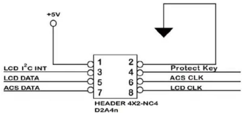
| PIN Description PIN Description | |||
| 1 Power (+5V) 2 GND | |||
| 3 LCD | Module Interrupt 4 Protect Key | ||
| 5 LCD | Module Serial Data 6 Fault/Activity Clock | ||
| 7 Fault/Activity Serial Data 8 LCD Module | |||
You can use one optional LCD front panel and keypad function to simply create the RAID volume. The LCD status panel also informs you the disk array's current operating status at a glance. The LCD configuration is described in a separate manual: RAID Card_LCD manual. The LCD housed in a 5½-inch half-height or 3.5-inch canister.

Figure 2-5, Connect to LCD Status Panel
Step 7. Adding a Battery Backup Module (Optional)
Please refer to Appendix B Battery Backup Module (ARC-6120BA-T121) for installing the BBM in your 6Gb/s SATA RAID controller.
Step 8. Re-check Fault LED Cable Connections (Optional)
Be sure that the proper failed drive channel information is displayed by the fault LEDs. An improper connection will tell the user to “Hot Swap” the wrong drive. This can result in removing the wrong disk (one that is functioning properly) from the controller. This can result in failure and loss of system data.
Step 9. Power up the System
Throughly check the installation, reinstall the computer cover, and reconnect the power cord cables. Turn on the power switch at the rear of the computer (if equipped) and then press the power button at the front of the host computer.
Step 10. Install the Controller Driver
For a new system:
- Driver installation usually takes places as part of operating system installation. Please refer to Chapter 4 "Diver Installation" for the detailed installation procedure.
For an existing system:
- To install the controller driver into the existing operating system. For the detailed installation procedure, please refer to the Chapter 4, "Driver Installation".
Step 11. Install ArcHTTP Proxy Server
The ARC-1203-2I firmware has embedded the web-browser McRAID storage manager. ArcHTTP proxy server will launch the web-browser McRAID storage manager. It provides all of the creation, management and monitor ARC-1203-2I RAID controller status. Please refer to the Chapter 5 for the detail "ArcHTTP Proxy Server Installation". For SNMP agent function, please see the "SNMP Operation & Installation" section in the Appendix C of the user manual.
Step 12. Configure Volume Set
With Areca series RAID cards, there are 4 methods to manage your ARC-1203-2I RAID controller. It can be configured by using the LCD with keypad, McBIOS RAID manager (terminal emulation) or McRAID storage manager (via ArcHTTP proxy utility).
- Method 1: Internal PCIe Connection (McBIOS RAID Manager) The ARC-1203-2I RAID controller can be configured via a BIOS start up McBIOS manager. The McBIOS RAID manager is firmware-based and is used to configure RAID sets and volume sets. Because the utility resides in the ARC-1203-2I RAID controller firmware, operation is independent of any operating systems on your computer. For additional information on using the BIOS on-screen to configure the RAID subsystem see the Chapter 3 of "BIOS Configuration" of the user manual.
- Method 2: Internal PCIe Connection (McRAID Storage Manager) You're now ready to use the McRAID storage manager to set up RAID volumes. Your ARC-1203-2I RAID controller can be configured by using McRAID storage manager (launched by ArcHTTP proxy server). ARC-1203-2I RAID controller has embedded the TCP/IP & web browser-based RAID manager in the firmware. User can use the standard web browsers to manage the RAID controller using ArcHTTP proxy server installed. For additional information on using the McRAID storage manager to configure the RAID controller see the Chapter 6 of "Web Browser-Based Configuration" of the user manual.
- Method 3: Front LCD Panel with Keypad (Optional) You can use LCD front panel and keypad function to simply create the RAID volume. The LCD status panel also informs you of the disk array's current operating status at a glance. For additional information on using the LCD to configure the RAID controller see the ARC1000_LCD manual on the shipping CD. The LCD provides a system of screens with areas for information, status indication, or menus. The LCD screen displays up to two lines at a time of menu items or other information.
Step 13. Format, Partition and Mount the ARC-1203-2I RAID Controller Volumes
After the volume set is ready for system accesses, it needs to be partitioned, formatted, and mounted by the operating system.
There are various steps, depending on what operating system you are using (Windows, Linux, FreeBSD or Mac, etc.). Detailed steps for each operating system are provided on their disk utility. After that, the ARC-1203-2I RAID controller can be fully used.
Step 14. Determining the Boot Sequences
The ARC-1203-2I RAID controller is a bootable device. You can use it as primary boot drive or secondary storage drive. If your system already contains a bootable device with an installed operating system, you can set up your system to boot a second operating system from the new ARC-1203-2I RAID controller volume.
For PC system:
To add a second bootable controller, you may need to enter setup of motherboard BIOS and change the device boot sequence so that the new ARC-1203-2I RAID controller volume heads the list. If the system BIOS setup does not allow this change, your system may be not configurable to allow the new ARC-1203-2I RAID controller volume to act as a second boot device.
For Apple Mac Pro system:
Areca controller has supported the EFI BIOS on the PCIe 2.0 6Gb/s SATA RAID controller. You have other alternatively to add volumes on the Intel-based Mac bootable device listing. You can follow the following procedures to add 6Gb/s SATA RAID controller on the Mac bootable device listing.
- Set the BIOS selection in System Controls: Advance Configuration to "EFI" option for Intel-based MacPro boot.
- Download OS X Mavericks and DiskMaker X. Follow the DiskMaker X to make a bootable OS X Mavericks USB install drive.
-
Restart your Mac and after you hear the chime sound, press the Option (Alt) key until you see the option to choose the flash drive to boot from.
-
Follow the on-screen prompts to complete Areca Volume Upgrade and Clean Install of OS X Mavericks. Power up the Intel-based Mac and Areca volume will be added in the bootable device automatically.
2.4 Summary of the installation
The flow chart below describes the installation procedures for 6Gb/s SATA RAID controllers.
![graph TD A["Chapter 2\nInsatall Controllers"] --> B["Chapter 3\nCreate Bootable or Data RAID Volume Using McBIOS RAID Manager"] B --> C["Chapter 4\nInstall OS/Device Driver on Bootable RAID Volume Set or Install Device Driver on Existing OS"] C --> D["Chapter 5\nInstall ArcHttp Proxy Server"] D -->…](/content/2026/05/990737/images/db40f88e85d2fc521bb14ea21723140918507129c7f9cd9241d9c95bb1d6114f.jpg)
These procedures includes hardware installation, the creation and configuration of a RAID volume through the McBIOS/McRAID manager, OS installation and installation of 6Gb/s SATA RAID controller software.
The software components configure and monitor the 6Gb/s SATA RAID controllers as following table.
| Configuration Utility Operating System Supported | |
| McBIOS RAID Manager OS-Independent | |
| McRAID Storage Manager (Via ArcHTTP proxy server) | Windows 10/8/2012/7/2008/Vista/XP/2003, Linux, FreeBSD, Solaris and Mac |
| SAP Monitor (Single Admin Portal to scan for multiple RAID units in the network, via ArcHTTP proxy server) | Windows 10/8/2012/7/2008/Vista/XP/2003 |
| SNMP Manager Console Integration Windows 10/8/2012/7/2008/Vista/XP/2003, Linux and FreeBSD | |
McRAID Storage Manager
Before launching the firmware-embedded web browser, McRAID storage manager through the PCIe bus, you need first to install the ArcHTTP proxy server on your server system. If you need additional information about installation and start-up of this function, see the McRAID Storage Manager section in Chapter 6 of the user manual.
ArcHTTP Proxy Server
ArcHTTP has to be installed for GUI RAID console (MRAID storage manager) to run. It is used to launch the web browser McRAID storage manager. It also runs as a service or daemon in the background that allows capturing of events for mail and SNMP traps notification. If you need additional information about installation and start-up of this function, see the ArcHTTP Proxy Server Installation section in Chapter 5 of the user manual.
CLI Utility
CLI (Command Line Interface) lets you set up and manage RAID controller through a command line interface. CLI performs many tasks at the command line. You can download CLI manual from Areca website or software CD
SNMP Manager Console Integration
There are two ways to transport SNMP data on the ARC-1203-2I RAID controller: in-band PCIe host bus interface or out-of-band built-in LAN interface. Enter the "SNMP Tarp IP Address" option on the firmware-embedded SNMP configuration function for user to select the SNMP data agent-side communication from the out-of-band built-in LAN interface. To use in-band PCIe host bus interface, keep blank on the "SNMP Tarp IP Address" options.
- In-Band-Using PCIe Host Bus Interface
In-band interface refers to management of the SNMP data of 6Gb/s SATA controllers from a PCIe host bus. In-band interface is simpler than out-of-band interface for it requires less hardware in its configuration. Since the 6Gb/s SATA RAID controller is already installed in the host system, no extra connection is necessary.
Just load the necessary in-band Areca SNMP extension agent for the controllers. Before launching the SNMP agent in the sever, you need first to enable the firmware-embedded SNMP community configuration and install Areca SNMP extension agent in your server system. If you need additional information about installation and start-up the function, see the SNMP Operation & Installation section in the Appendix C of the user manual.
Single Admin Portal (ArcSAP) Monitor
This utility can scan for multiple RAID units in the local and remote systems and provide an effective mechanism to configure and monitor your RAID units. For additional information, see the utility manual (ArcSAP) in the packaged CD or download it from the web site http://www.areca.com.tw
3. McBIOS RAID Manager
The system mainboard BIOS automatically configures the following 6Gb/s SATA RAID controller parameters at power-up:
- I/O Port Address
- Interrupt Channel (IRQ)
- Controller ROM Base Address
Use McBIOS RAID manager to further configure the 6Gb/s SATA RAID controller to suit your server hardware and operating system.
3.1 Starting the McBIOS RAID Manager
This section explains how to use the McBIOS RAID manager to configure your RAID system. The McBIOS RAID manager is designed to be user-friendly. It is a menu-driven program, residing in the firmware, which allows you to scroll through various menus and sub-menus and select among the predetermined configuration options.
When starting a system with a 6Gb/s SATA RAID controller installed, it will display the following message on the monitor during the start-up sequence (after the system BIOS startup screen but before the operating system boots):
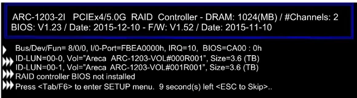
The McBIOS RAID manager message remains on your screen for about nine seconds, giving you time to start the configuration menu by pressing Tab or F6. If you do not wish to enter configuration menu, press ESC to skip configuration immediately. When activated, the McBIOS RAID manager window appears showing a selection dialog box listing the 6Gb/s SATA RAID controllers that are installed in the system. The legend at the bottom of the screen shows you what keys are enabled for the windows.
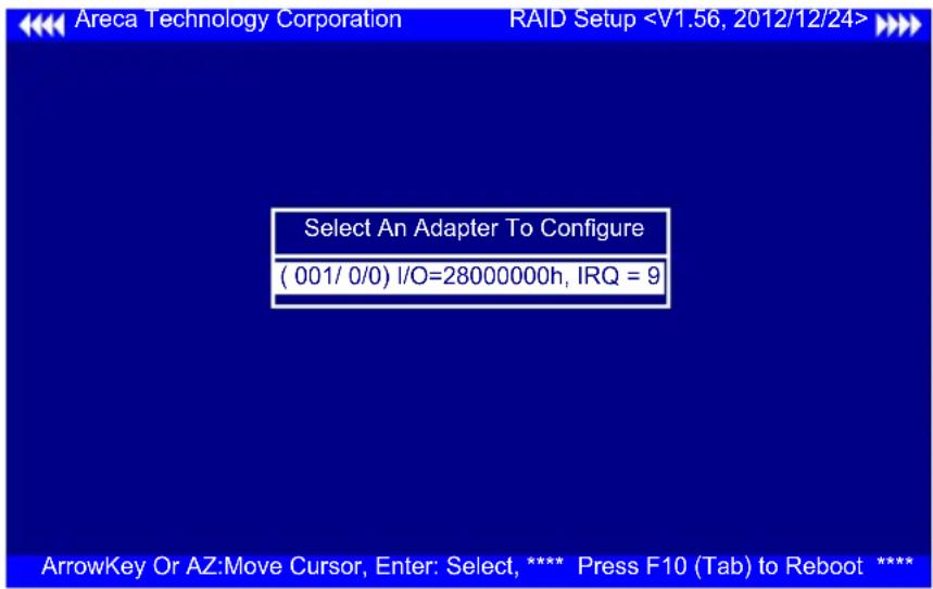
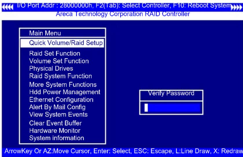
Use the Up and Down arrow keys to select the controller you want to configure. While the desired controller is highlighted, press the Enter key to enter the main menu of the McBIOS RAID manager.

3.2 McBIOS RAID manager
The McBIOS RAID manager is firmware-based and is used to configure RAID sets and volume sets. Because the utility resides in the 6Gb/s SATA RAID controller firmware, operation is independent of any operating systems on your computer. This utility can be used to:
- Create RAID sets,
-
Expand RAID sets,
-
Add physical drives,
- Define volume sets,
- Modify volume sets,
- Modify RAID level/stripe size,
- Define pass-through disk drives,
- Modify system functions and
- Designate drives as hot spares.
3.3 Configuring Raid Sets and Volume Sets
You can configure RAID sets and volume sets with McBIOS RAID manager automatically. Using "Quick Volume/Raid Setup" or manually using "Raid Set/Volume Set Function". Each configuration method requires a different level of user input. The general flow of operations for RAID set and volume set configuration is:
| Step Action | |
| 1 Designate hot spares/pass-through drives (optional). | |
| 2 Choose a configuration method. | |
| 3 Create RAID sets using the available physical drives. | |
| 4 Define volume sets using the space available in the RAID set. | |
| 5 Initialize the volume sets and use volume sets (as logical drives) in the host OS. |
3.4 Designating Drives as Hot Spares
Any unused disk drive that is not part of a RAID set can be designated as a hot spare. The "Quick Volume/Raid Setup" configuration will add the spare disk drive and automatically display the appropriate RAID level from which the user can select. For the "Raid Set Function" configuration option, the user can use the "Create Hot Spare" option to define the hot spare disk drive.
When a hot spare disk drive is being created using the "Create Hot Spare" option (in the "Raid Set Function"), all unused physical devices connected to the current controller appear:
Choose the target disk by selecting the appropriate check box. Press Enter key to select a disk drive, and press Yes in the "Create Hot Spare" to designate it as a hot spare.
3.5 Using Quick Volume /Raid Setup Configuration
"Quick Volume / Raid Setup configuration" collects all available drives and includes them in a RAID set. The RAID set you created is associated with exactly one volume set. You will only be able to modify the default RAID level, stripe size and capacity of the new volume set. Designating drives as hot spares is also possible in the "Raid Level" selection option. The volume set default settings will be:
| Parameter Setting | |
| Volume Name ARC-1203-VOL#00 | |
| SCSI Channel/SCSI ID/SCSI LUN 0/0/0 | |
| Cache Mode Write-Back | |
| Tag Queuing Yes |
The default setting values can be changed after configuration is completed. Follow the steps below to create arrays using the "Raid Set / Volume Set" method:
| Step Action | |
| 1 Choose "Quick Volume /Raid Setup" from the main menu. The available RAID levels with hot spare for the current volume set drive are displayed. | |
| 2 It is recommended that you use drives of the same capacity in a specific array. If you use drives with different capacities in an array, all drives in the RAID set will be set to the capacity of the smallest drive in the RAID set.The numbers of physical drives in a specific array determines which RAID levels that can be implemented in the array.RAID 0 requires 1 or more physical drives.RAID 1 requires at least 2 physical drives.Highlight the desired RAID level for the volume set and press the Enter key to confirm. | |
| 3 The capacity for the current volume set is entered after highlighting the desired RAID level and pressing the Enter key.The capacity for the current volume set is displayed. Use the UP and DOWN arrow keys to set the capacity of the volume set and press the Enter key to confirm. The available stripe sizes for the current volume set are then displayed. | |
| 4 | Use the UP and DOWN arrow keys to select the current volume set stripe size and press the Enter key to confirm. This parameter specifies the size of the stripes written to each disk in a RAID 0 or 1 volume set. You can set the stripe size to 4KB, 8KB, 16KB, 32KB, 64KB, 128KB, 256KB, 512KB, or 1024KB. A larger stripe size provides better read performance, especially when the computer preforms mostly sequential reads. However, if the computer preforms random read requests more often, choose a smaller stripe size. |
| 5 When you are finished defining the volume set, press the Yes key to confirm the “Quick Volume And Raid Set Setup” function. | |
| 6 | Foreground (Fast Completion) Press Enter key to define fast initialization or selected the Background (Instant Available) or No Init (To Rescue Volume). In the “Background Initialization”, the initialization proceeds as a background task, the volume set is fully accessible for system reads and writes. The operating system can instantly access to the newly created arrays without requiring a reboot and waiting the initialization complete. In “Foreground Initialization”, the initialization proceeds must be completed before the volume set ready for system accesses. In “No Init”, there is no initialization on this volume. |
| 7 Initialize the volume set you have just configured | |
| 8 If you need to add additional volume set, using main menu “Create Volume Set” function. | |
3.6 Using Raid Set/Volume Set Function Method
In "Raid Set Function", you can use the "Create Raid Set" function to generate a new RAID set. In "Volume Set Function", you can use the "Create Volume Set" function to generate an associated volume set and configuration parameters.
If the current controller has unused physical devices connected, you can choose the "Create Hot Spare" option in the "Raid Set Function" to define a global hot spare. Select this method to configure new RAID sets and volume sets. The "Raid Set/Volume Set Function" configuration option allows you to associate volume sets with partial and full RAID sets.
| Step | Action |
| 1 To | setup the hot spare (option), choose "Raid Set Function" from the main menu. Select the "Create Hot Spare" and press theEnterkey to define the hot spare. |
| 2 Choose "Raid Set Function" from the main menu. Select "Create Raid Set" and press theEnterkey. | |
| 3 The | "Select a Drive For Raid Set" window is displayed showing the SATA drives connected to the 6Gb/s SATA RAID controller. |
| 4 | Press theUPandDOWNarrow keys to select specific physical drives.Press theEnterkey to associate the selected physical drive with the current RAID set.It is recommended that you use drives of the same capacity in a specific array. If you use drives with different capacities in an array, all drives in the RAID set will be set to the capacity of the smallest drive in the RAID set.The numbers of physical drives in a specific array determines which RAID levels that can be implemented in the array.RAID 0 requires 1 or more physical drives.RAID 1 requires at least 2 physical drives. |
| 5 After | adding the desired physical drives to the current RAID set, press theEnterto confirm the "Create Raid Set" function. |
| 6 | An "Edit The Raid Set Name" dialog box appears. Enter 1 to 15 alphanumeric characters to define a unique identifier for this new RAID set. The default RAID set name will always appear as Raid Set. #. PressEnterkeyto finish the name editing. |
| 7 Press | theEnterkey when you are finished creating the current RAID set. To continue defining another RAID set, repeat step 3. To begin volume set configuration, go to step 8. |
| 8 Choose | the "Volume Set Function" from the main menu. Select "Create Volume Set" and press theEnterkey. |
| 9 Choose | a RAID set from the "Create Volume From Raid Set" window.Press theYeskey to confirm the selection. |
| 10 | Choosing Foreground (Fast Completion) PressEnterkey to define fast initialization or selected the Background (Instant Available) or No Init (To Rescue Volume). In the "Background Initialization", the initialization proceeds as a background task, the volume set is fully accessible for system reads and writes. The operating system can instantly access to the newly created arrays without requiring a reboot and waiting the initialization complete. In "Foreground Initialization", the initialization proceeds must be completed before the volume set ready for system accesses. In "No Init", there is no initialization on this volume. |
| 11 If | space remains in the RAID set, the next volume set can be configured.Repeat steps 8 to 10 to configure another volume set. |
3.7 Main Menu
The main menu shows all functions that are available for executing actions, which is accomplished by clicking on the appropriate link.

Note:
The manufacture default password is set to 0000; this password can be modified by selecting "Change Password" in the "Raid System Function" section.
| Option Description | |
| Quick Volume/Raid Setup Create a default configuration based on the number of physical disk installed | |
| Raid Set Function Create a customized RAID set | |
| Volume Set Function Create a customized volume set | |
| Physical Drives View individual disk information | |
| Raid System Function Setup the RAID system configuration | |
| Hdd Power Management Manage HDD power based on usage patterns | |
| View System Events Record all system events in the buffer | |
| Clear Event Buffer Clear all information in the event buffer | |
| Hardware Monitor Show the hardware system environment status | |
| System Information View the controller system information |
This password option allows user to set or clear the RAID controller's password protection feature. Once the password has been set, the user can only monitor and configure the RAID controller by providing the correct password. The password is used to protect the RAID controller from unauthorized entry. The controller will prompt for the password only when entering the main menu from the initial screen. The RAID controller will automatically return to the initial screen when it does not receive any command in five minutes.
3.7.1 Quick Volume/Raid Setup
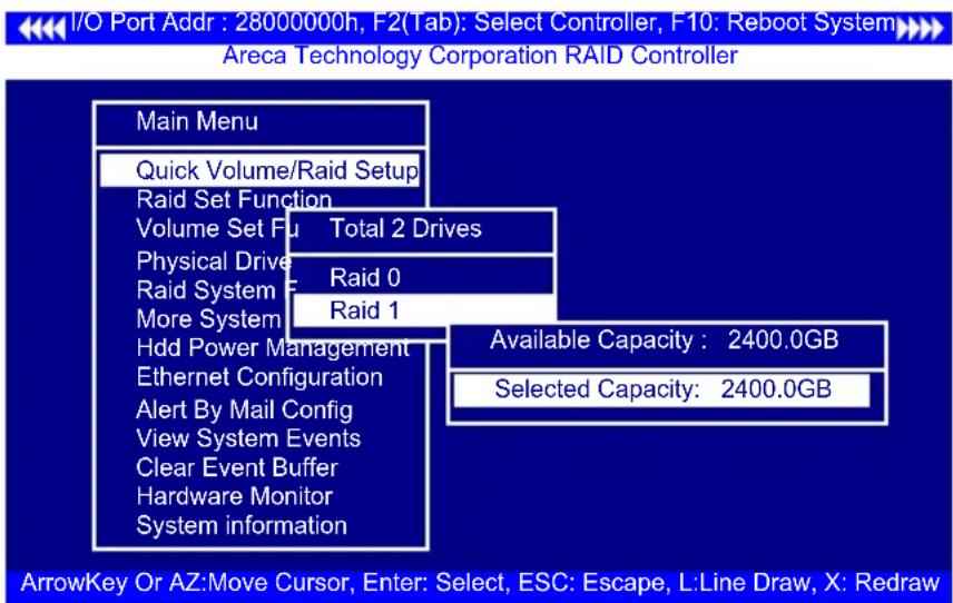
"Quick Volume/Raid Setup" is the fastest way to prepare a RAID set and volume set. It requires only a few keystrokes to complete. Although disk drives of different capacity may be used in the RAID set, it will use the capacity of the smallest disk drive as the capacity of all disk drives in the RAID set. The "Quick Volume/Raid Setup" option creates a RAID set with the following properties:
- All of the physical drives are contained in one RAID set.
- The RAID level, hot spare, capacity, and stripe size options are selected during the configuration process.
- When a single volume set is created, it can consume all or a portion of the available disk capacity in this RAID set.
- If you need to add an additional volume set, use the main menu "Create Volume Set" function.
The total number of physical drives in a specific RAID set determine the RAID levels that can be implemented within the RAID set. Select "Quick Volume/Raid Setup" from the main menu; all possible RAID level will be displayed on the screen.

If volume capacity will exceed 2TB, controller will show the "Greater Two TB Volume Support" sub-menu.

• No
It keeps the volume size with max. 2TB limitation.
- Use 64bit LBA
This option use 16 bytes CDB instead of 10 bytes. The maximum volume capacity up to 512TB. For any hard disk drives working in the 4K native mode in the Raid set, the volume set directly sets and exposes 4KB sector size to the operating system. This option works on different OS which supports 16 bytes CDB. Such as:
Windows 2003 with SP1 or later
Linux kernel 2.6.x or later
- Use 4K Block
This option uses 16 bytes CDB and changes the sector size from default 512 bytes to 4k bytes. Windows XP only supports maximum volume capacity is up to 16TB.
A single volume set is created and consumes all or a portion of the disk capacity available in this RAID set. Define the capacity of volume set in the "Available Capacity" popup. The default value for the volume set, which is 100% of the available capacity, is displayed in the selected capacity. Use the UP and DOWN arrow key to set capacity of the volume set and press Enter key to accept this value. If the volume set uses only part of the RAID set capacity, you can use the "Create Volume Set" option in the main menu to define additional volume sets.
Stripe Size This parameter sets the size of the stripe written to each disk in a RAID 0 or 1 logical drive. You can set the stripe size to 4KB, 8KB, 16KB, 32KB, 64KB, 128KB, 256KB, 512KB, or 1024KB.
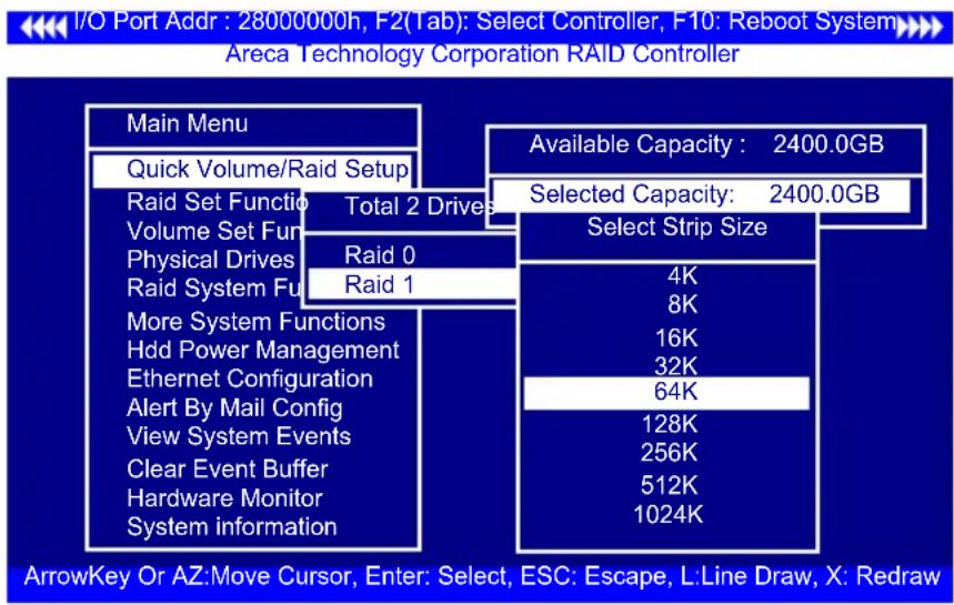
A larger stripe size produces better-read performance, especially if your computer does mostly sequential reads. However, if you are sure that your computer performs random reads more often, select a smaller stripe size.
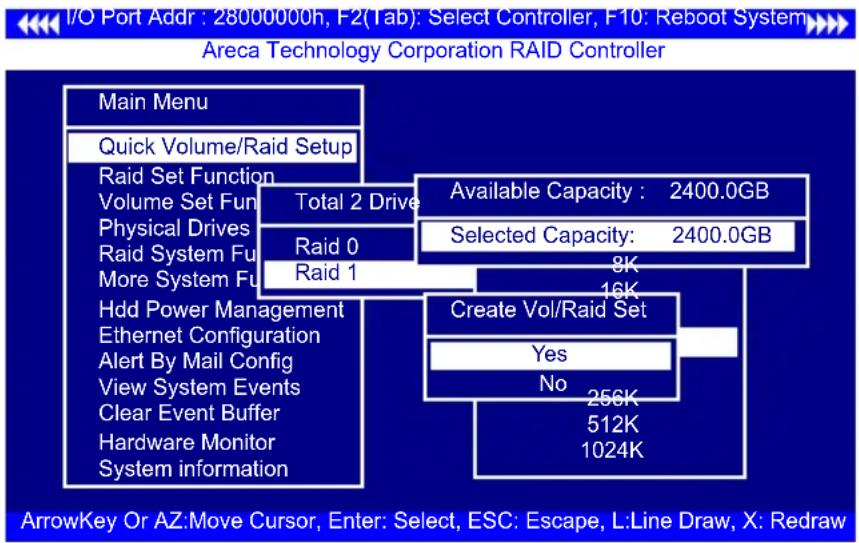
Press Yes key in the "Create Vol/Raid Set" dialog box, the RAID set and volume set will start to initialize it.
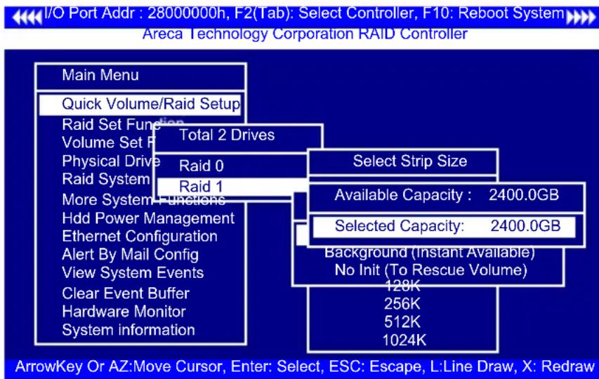
Select "Foreground (Faster Completion)" or "Background (Instant Available)" for initialization and "No Init (To Rescue Volume)" for recovering the missing RAID set configuration.
3.7.2 Raid Set Function
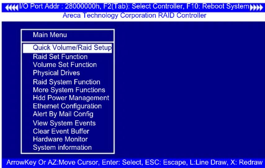
Manual configuration gives complete control of the RAID set setting, but it will take longer to configure than "Quick Volume/Raid Setup" configuration. Select "Raid Set Function" to manually configure the RAID set for the first time or delete existing RAID sets and reconfigure the RAID set.
3.7.2.1 Create Raid Set
The following summaries are the RAID set features for the 6Gb/s SATA RAID controller. Up to 2 disk drives can be included in a single RAID set.
To define a RAID set, follow the procedures below:
(1). Select "Raid Set Function" from the main menu.
(2). Select "Create Raid Set" from the "Raid Set Function" dialog box.
(3). A "Select IDE Drive For Raid Set" window is displayed showing the SATA drives connected to the current controller. Press the UP and DOWN arrow keys to select specific physical drives. Press the Enter key to associate the selected physical drive with the current RAID set. Repeat this step; the user can add as many disk drives as are available to a single RAID set. When finished selecting SATA drives for RAID set, press Esc key. A "Create Raid Set Confirmation" screen will appear, select the Yes option to confirm it.

(4). An "Edit The Raid Set Name" dialog box appears. Enter 1 to 15 alphanumeric characters to define an unique identifier for the RAID set. The default RAID set name will always appear as Raid Set #.
(5). Repeat steps (3) to define another RAID sets.

3.7.2.2 Delete Raid Set
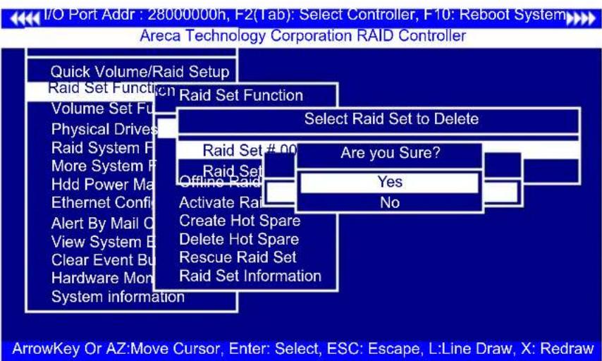
To completely erase and reconfigure a RAID set, you must first delete it and re-create the RAID set. To delete a RAID set, select the RAID set number that you want to delete in the "Select Raid Set To Delete" screen. Then "Delete Raid Set" dialog box will appear, press the Yes to delete it. Warning, data on RAID set will be lost if this option is used.
3.7.2.3 Expand Raid Set
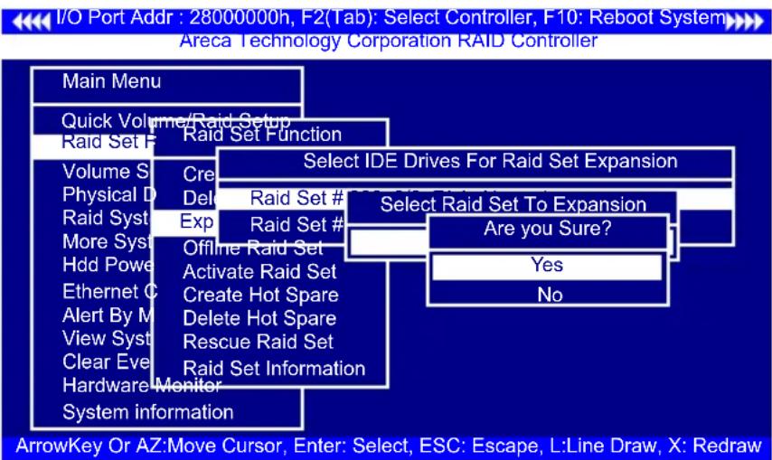
Instead of deleting a RAID set and recreating it with additional disk drives, the "Expand Raid Set" function allows the users to add disk drives to the RAID sets that have already been created.
To expand a RAID set:
- Select the "Expand Raid Set" option. If there is an available disk, then the "Select SATA Drives For Raid Set Expansion" screen appears.
- Select the target RAID set by clicking on the appropriate radius button. Select the target disk by clicking on the appropriate check box.
- Press the Yes key to start the expansion on the RAID set.
The new additional capacity can be utilized by one or more volume sets. The volume sets associated with this RAID set appear for you to have chance to modify RAID level or stripe size. Follow the instruction presented in the "Modify Volume Set" to modify the volume sets; operation system specific utilities may be required to expand operating system partitions.
Caution:
RAID set expansion is a quite critical process, we strongly recommend customer backup data before expand. Unexpected accident may cause serious data corruption.
Note:
Once the "Expand Raid Set" process has started, user can not stop it. The process must be completed.
- Migrating
Migration occurs when a disk is added to a RAID set. Migrating state is displayed in the RAID state area of "The Raid Set Information" screen when a disk is being added to a RAID set. Migrating state is also displayed in the associated volume state area of the "Volume Set Information" which belongs this RAID set.

3.7.2.4 Offline Raid Set
This function is for customer being able to unmount and re-mount a multi-disk volume. All Hdds of the selected RAID set will be put into offline state and spun down and fault LED will be in fast blinking mode.
I/O Port Addr : 28000000h, F2(Tab): Select Controller, F10: Reboot System Areca Technology Corporation RAID Controller
![graph TD A["Main Menu"] --> B["Quick Volume/Raid Setup"] B --> C["Raid Set Function"] C --> D["Volume Set Function"] D --> E["Physical Drives"] E --> F["Raid System Function"] F --> G["More System Function"] G --> H["Hdd Power Management"] H --> I["Ethernet Configuration"] I --> J["Alert By Mail Con…](/content/2026/05/990737/images/2d6bc7bc3299fc566bdc65b1b3f784d3cdb18759685f4ac04be227cade20bcf0.jpg)
3.7.2.5 Activate Incomplete Raid Set
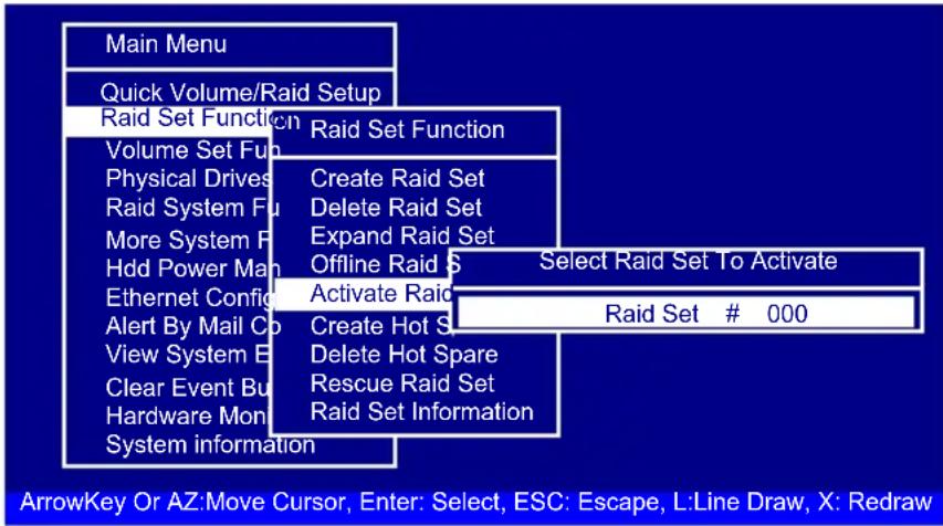
The following screen is used to activate the RAID set after one of its disk drive was removed in the power off state.
When one of the disk drives is removed in power off state, the RAID set state will change to "Incomplete State". If user wants to continue to work while the 6Gb/s SATA RAID controller is powered on, the user can use the "Activate Incomplete Raid Set" option to active the RAID set. After user selects this function, the RAID state will change to "Degraded Mode" and start to work.
I/O Port Addr : 28000000h, F2(Tab): Select Controller, F10: Reboot System Areca Technology Corporation RAID Controller
3.7.2.6 Create Hot Spare
When you choose the "Create Hot Spare" option in the "Raid Set Function", all unused physical devices connected to the current controller will result in the screen.
Select the target disk by clicking on the appropriate check box. Press the Enter key to select a disk drive and press Yes in the "Create Hot Spare" to designate it as a hot spare.
The “Create Hot Spare” gives you the ability to define a global or dedicated hot spare. Unlike “Global Hot Spare” which can be used with any RAID sets, “Dedicated Hot Spare” can only be used with a specific RAID set or Enclosure. Under “Global For SSD or HDD” option, SSD hot spare is used to rebuild failed SSD and HDD hot spare for rebuild failed HDD. When a disk drive fails in the RAID set or enclosure with a dedicated hot spare is pre-set, data on the disk drive is rebuild automatically on the dedicated hot spare disk.

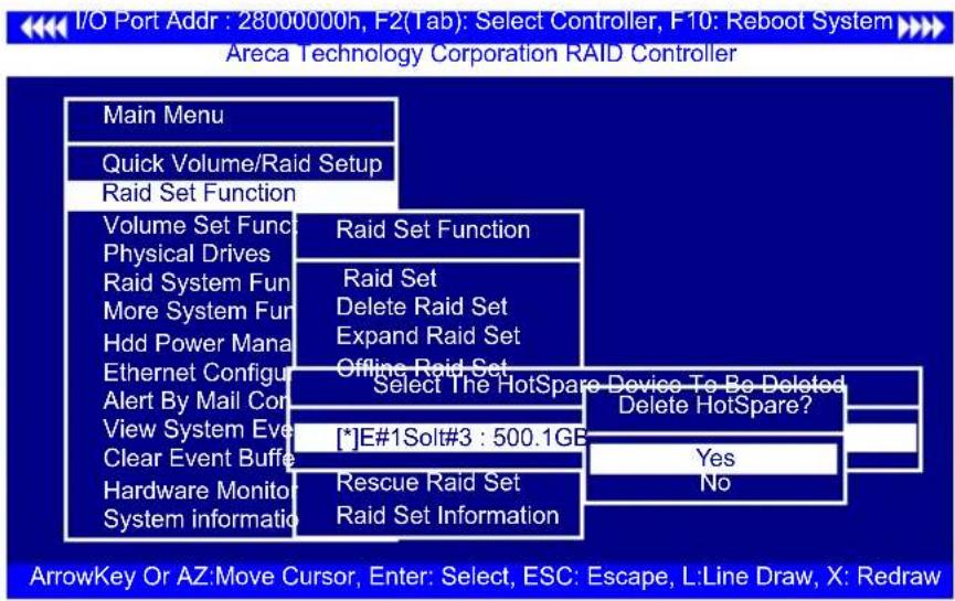
3.7.2.7 Delete Hot Spare
Select the target hot spare disk to delete by clicking on the appropriate check box.
Press the Enter key to select a hot spare disk drive, and press Yes in the "Delete Hot Spare" screen to delete the hot spare.
3.7.2.8 Rescue Raid Set
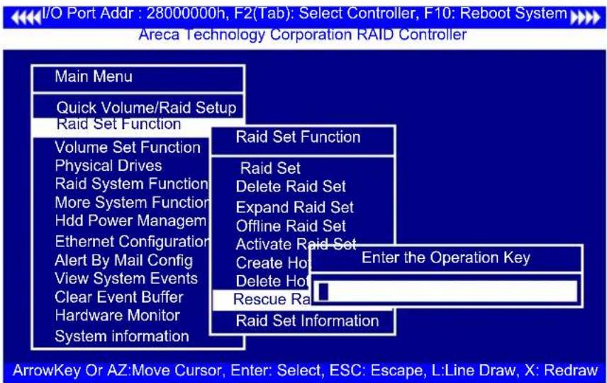
When the system is powered off in the RAID set update/creation period, it possibly could disappear due to this abnormal condition. The “RESCUE” function can recover the missing RAID set information. The RAID controller uses the time as the RAID set signature. The RAID set may have different time after the RAID set is recovered. The “SIGANT” function can regenerate the signature for the RAID set.
Caution:
Please contact us to make sure if you need to use rescue function. Improperly usage may cause configuration corruption.
Once can manually fail a drive, which is useful in kill-off slow speed disk. There is nothing physically wrong with the disk. A manually failed the drive can be rebuilt by the hot spare and brought back on-line.
3.7.2.9 Raid Set Information
To display RAID set information, move the cursor bar to the desired RAID set number, then press the Enter key. The "Raid Set Information" will appear. You can only view information for the RAID set in this screen.

3.7.3 Volume Set Function
A volume set is seen by the host system as a single logical device; it is organized in a RAID level within the controller utilizing one or more physical disks. RAID level refers to the level of data performance and protection of a volume set. A volume set can consume all of the capacity or a portion of the available disk capacity of a RAID set. Multiple volume sets can exist on a RAID set. If multiple volume sets reside on a specified RAID set, all volume sets will reside on all physical disks in the RAID set. Thus each volume set on the RAID set will have its data spread evenly across all the disks in the RAID set rather than one volume set using some of the available disks and another volume set using other disks.
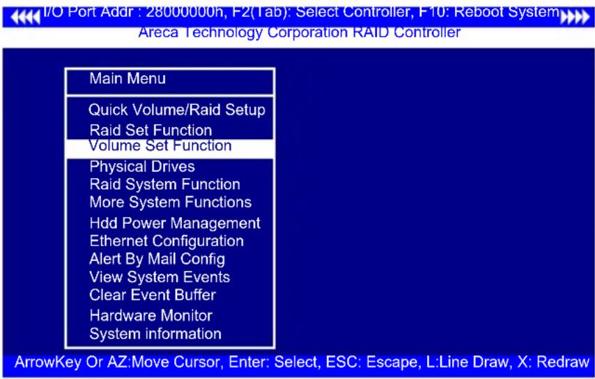
The following summaries are the volume set features for the 6Gb/s SATA RAID controller.
- Volume sets of different RAID levels may coexist on the same RAID set and up to 128 volume sets per controller.
- Up to 128 volume sets can be created in a RAID set.
- The maximum addressable size of a single volume set is not limited to 2TB, because the controller is capable of 64-bit LBA mode. However the operating system itself may not be capable of addressing more than 2TB.
3.7.3.1 Create Volume Set (0/1)
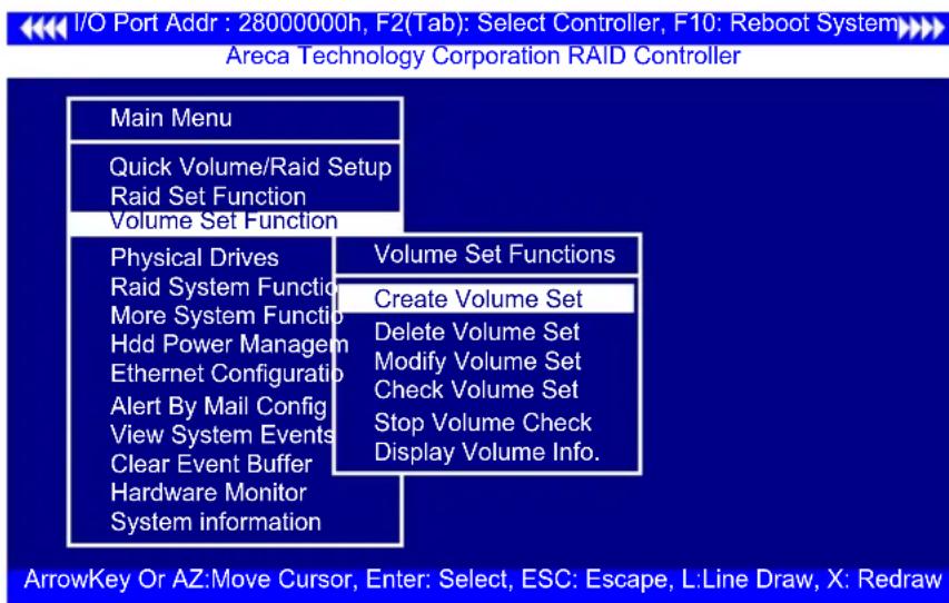
To create a volume set, following the steps:
- Select the "Volume Set Function" from the main menu.
- Choose the "Create Volume Set" from "Volume Set Functions" dialog box screen.
-
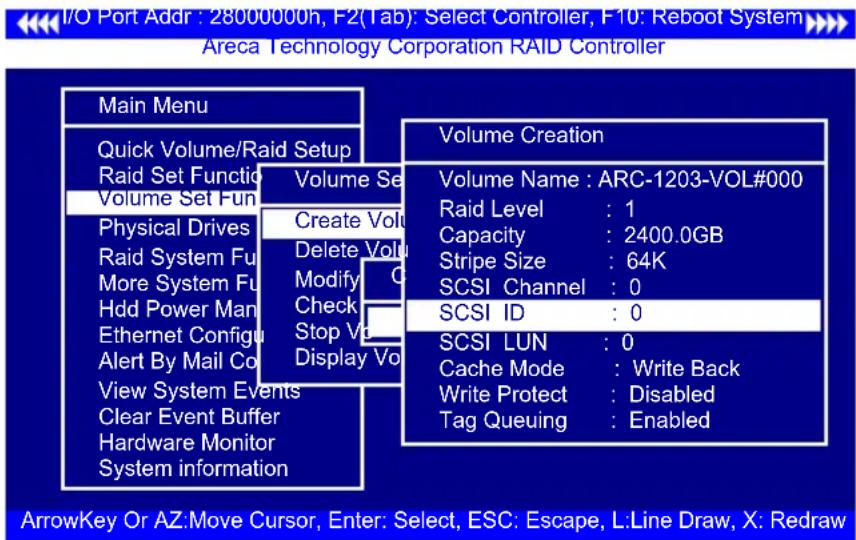
The "Create Volume From Raid Set" appears. This screen displays the existing arranged RAID sets. Select the RAID set number and press the Enter key. The "Volume Creation" dialog is displayed in the screen.
-
The new create volume set attribute allows user to select the Volume Name, Raid level, Capacity, Strip Size, SCSI Channel/SCSI ID/SCSI Lun, Cache Mode, and Tagged Command Queuing.

-
After completed the modification of the volume set, press the Esc key to confirm it. An "Initialization Mode" screen appears.
-
Select "Foreground (Faster Completion)" for faster initialization of the selected volume set.
- Select "Background (Instant Available)" for normal initialization of the selected volume set.
- Select "No Init (To Rescue Volume)" for no initialization of the selected volume.

- Repeat steps 3 to 5 to create additional volume sets.
- The initialization percentage of volume set will be displayed at the button line.
Note:
Controller starts to initialize the volume in two conditions
- Stay in controller bios manager or
- Boot into OS and the controller driver loaded.
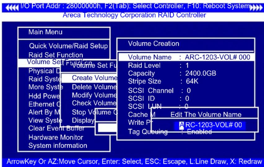
• Volume Name
The default volume name will always appear as ARC-1203-VOL #. You can rename the volume set providing it does not exceed the 15 characters limit.
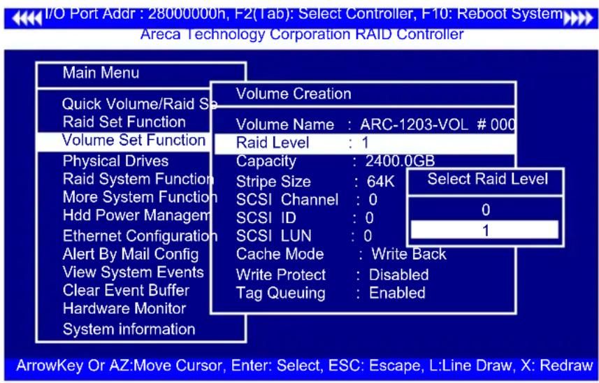
- Raid Level
Set the "Raid Level" for the volume set. Highlight "Raid Level" and press the Enter key. The available RAID levels for the current volume set are displayed. Select a RAID level and press the Enter key to confirm.
- Capacity
The maximum available volume size is the default value for the first setting. Enter the appropriate volume size to fit your application. The capacity value can be increased or decreased by the UP and DOWN arrow keys. The capacity of each volume set must be less than or equal to the total capacity of the RAID set on which it resides.

If volume capacity will exceed 2TB, controller will show the "Greater Two TB Volume Support" sub-menu.

- No
When this option is enabled, it keeps the volume size with max. 2TB limitation. For any hard disk drives working in the 4K native mode in the Raid set, the volume set directly sets and exposes 4KB sector size to the operating system.
- Use 64bit LBA
This option use 16 bytes CDB instead of 10 bytes. The maximum volume capacity up to 512TB. For any hard disk drives working in the 4K native mode in the Raid set, the volume set directly sets and exposes 4KB sector size to the operating system. This option works on different OS which supports 16 bytes CDB. Such as:
Windows 2003 with SP1 or later
Linux kernel 2.6.x or later
- Use 4K Block
This option uses 16 bytes CDB and changes the sector size from default 512 bytes to 4k bytes. Windows XP only supports maximum volume capacity is up to 16TB.
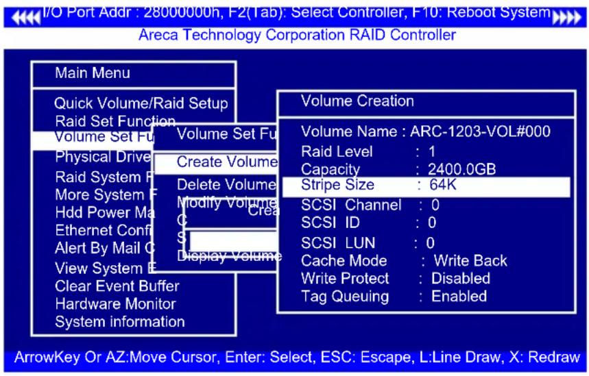
- Stripe Size
This parameter sets the size of segment written to each disk in a RAID 0 or 1 logical drive. You can set the stripe size to 4KB, 8KB, 16KB, 32KB, 64KB, 128KB, 256KB, 512KB, or 1024KB.
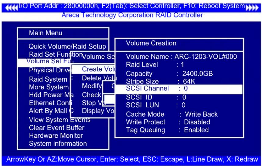
The 6Gb/s SATA RAID controller function simulates an external SCSI RAID controller. The host bus represents the SCSI channel. Choose the "SCSI Channel". A "Select SCSI Channel" dialog box appears; select the channel number and press the Enter key to confirm it.
• SCSI ID
Each device attached to the 6Gb/s SATA RAID controller, as well as the 6Gb/s SATA RAID controller itself, must be assigned an unique SCSI ID number. A SCSI channel can connect up to 15 devices. It is necessary to assign a SCSI ID to each device from a list of available SCSI IDs.
- SCSI LUN
Each SCSI ID can support up to 8 LUNs. Most 6Gb/s SATA controllers treat each LUN as if it were a SATA disk.

- Cache Mode
User can set the cache mode to either "Write Through" or "Write Back".

- Write Protect
When "Write Protect" is enabled on the "Create Volume Set", host commands fail if they are issued to a volume in that RAID controller and attempt to modify a volume's data or attributes. "Write Protection" is used primarily for customer-initiated disaster recovery testing.

- Tag Queuing
This option, when enabled, can enhance overall system performance under multi-tasking operating systems. The Command Tag (Drive Channel) function controls the SATA command tag queuing support for each drive channel. This function should normally remain be enabled. Disabled this function only when using older drives that do not support command tag queuing.

3.7.3.2 Delete Volume Set
To delete volume set from a RAID set, move the cursor bar to the "Volume Set Functions" menu and select the "Delete Volume Set" item, then press the Enter key. The "Volume Set Functions" menu will show all Raid Set # items. Move the cursor bar to a RAID set number, then press the Enter key to show all volume sets within that RAID set. Move the cursor to the volume set number that is to be deleted and press the Enter key to delete it.

3.7.3.3 Modify Volume Set
Use this option to modify volume set configuration. To modify volume set values from RAID set system function, move the cursor bar to the "Modify Volume Set" item, then press the Enter key. The "Volume Set Functions" menu will show all RAID set items. Move the cursor bar to a RAID set number item, then press the Enter key to show all volume set items. Select the volume set from the list to be changed, press the Enter key to modify it.
As shown, volume information can be modified at this screen. Choose this option to display the properties of the selected volume set. But user can only modify the last volume set capacity.

3.7.3.3.1 Volume Growth
Use "Expand Raid Set" function to add disk to a RAID set. The additional capacity can be used to enlarge the last volume set size or to create another volume set. The "Modify Volume Set" function can support the "Volume Modification" function. To expand the last volume set capacity, move the cursor bar to the "Capacity" item and entry the capacity size. When finished the above action, press the ESC key and select the Yes option to complete the action. The last volume set starts to expand its capacity.
To expand an existing volume noticed:
- Only the last volume can expand capacity.
- When expand volume capacity, you can't modify stripe size or modify RAID revel simultaneously.
- You can expand volume capacity, but can't reduce volume capacity size.
- After volume expansion, the volume capacity can not be decreased.
For greater 2TB expansion:
- If your system installed in the volume, don't expand the volume capacity greater 2TB; except your OS and RAID controller can support boot up from a greater 2TB capacity device.
- Expand over 2TB used 64bit LBA mode. Please make sure your OS supports 64bit LBA before expand it.
3.7.3.3.2 Volume Set Migration
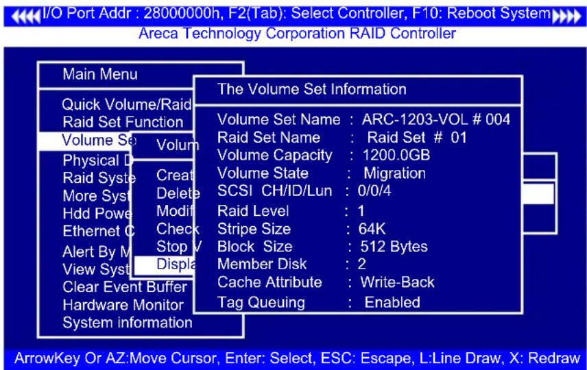
Migrating occurs when a volume set is migrating from one RAID level to another, when a volume set strip size changes, or when a disk is added to a RAID set. Migration state is displayed in the volume state area of the "Volume Set Information" screen.
Note:
Power failure may damage the migration data. Please back-up the RAID data before you start the migration function.
3.7.3.4 Check Volume Set
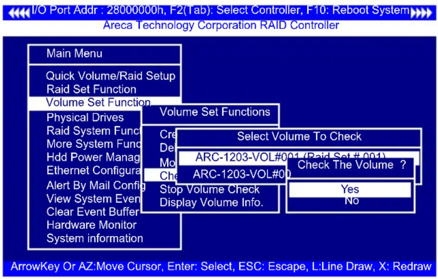
Use this option to verify the correctness of the redundant data in a volume set. For example, in a system with a dedicated parity disk drive, a volume set check entails computing the parity of the data disk drives and comparing those results to the contents of the dedicated parity disk drive. To check volume set, move the cursor bar to the "Check Volume Set" item, then press the Enter key. The "Volume Set Functions" menu will show all RAID set number items. Move the cursor bar to a RAID set number item and then press the Enter key to show all volume set items. Select the volume set to be checked from the list and press Enter key to select it. After completed the selection, the confirmation screen appears, press Yes to start the check.
3.7.3.5 Stop Volume Set Check
Use this option to stop all of the "Check Volume Set" operations.
3.7.3.6 Display Volume Set Info.
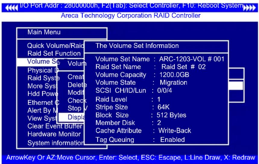
To display volume set information, move the cursor bar to the desired volume set number and then press the Enter key. The "Volume Set Information" screen will be shown. You can only view the information of this volume set in this screen, but can not modify it.
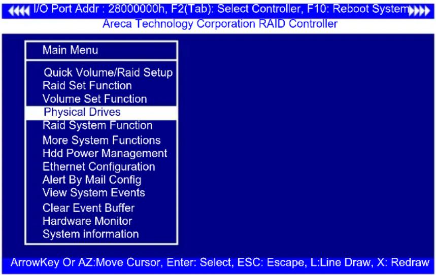
3.7.4 Physical Drives
Choose this option from the main menu to select a physical disk and perform the operations listed above. Move the cursor bar to an item, then press Enter key to select the desired function.
3.7.4.1 View Drive Information
When you choose this option, the physical disks connected to the 6Gb/s SATA RAID controller are listed. Move the cursor to the desired drive and press Enter key to view drive information.

3.7.4.2 Create Pass-Through Disk
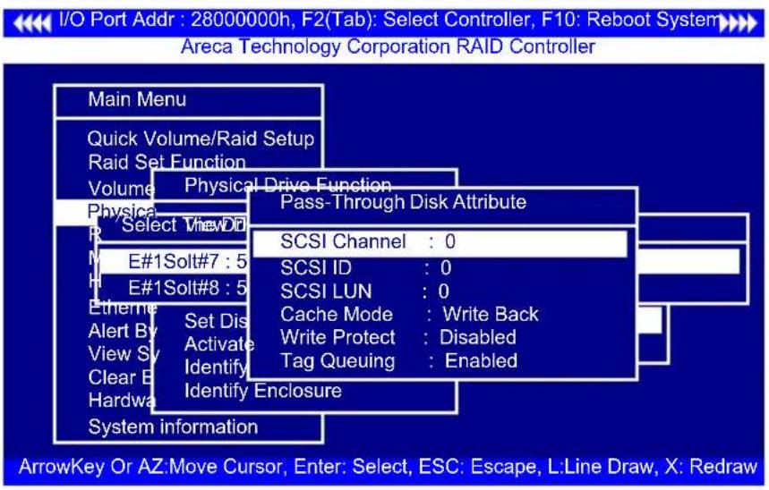
A pass-through disk is not controlled by the 6Gb/s SATA RAID controller firmware and thus cannot be a part of a volume set. The disk is available directly to the operating system as an individual disk. It is typically used on a system where the operating system is on a disk not controlled by the 6Gb/s SATA RAID controller firmware. The SCSI Channel/SCSI ID/SCSI LUN, Cache Mode, Write Protect and Tag Queuing must be specified to create a pass-through disk.
3.7.4.3 Modify Pass-Through Disk
Use this option to modify "Pass-Through Disk Attributes". To select and modify a pass-through disk from the pool of pass-through disks, move the "Modify Pass-Through Drive" option and then press the Enter key. The "Physical Drive Function" menu will show all pass-through drive number options. Move the cursor bar to the desired number and then press the Enter key to show all pass-through disk attributes. Select the parameter from the list to be changed and then press the Enter key to modify it.
3.7.4.4 Delete Pass-Through Disk
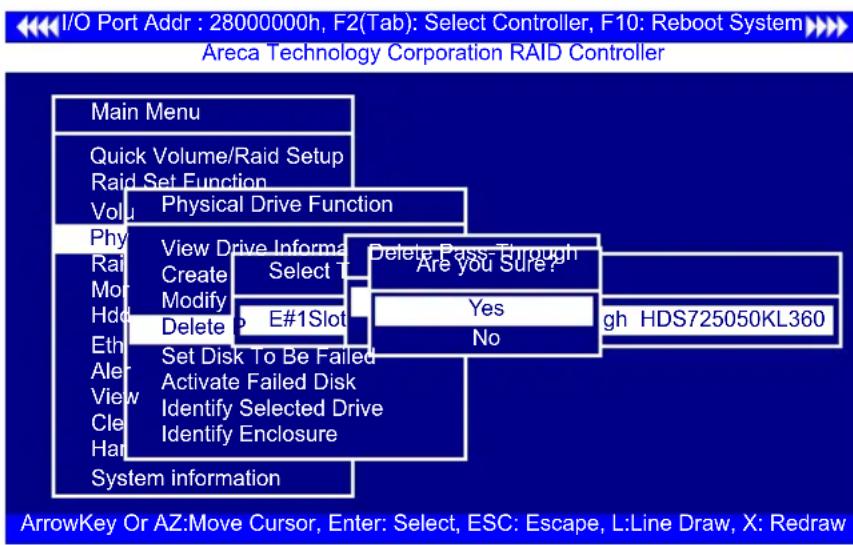
To delete a pass-through drive from the pass-through drive pool, move the cursor bar to the "Delete Pass-Through Drive" item, then press the Enter key. The "Delete Pass-Through confirmation" screen will appear; select Yes to delete it.
3.7.4.5 Set Disk To Be Failed
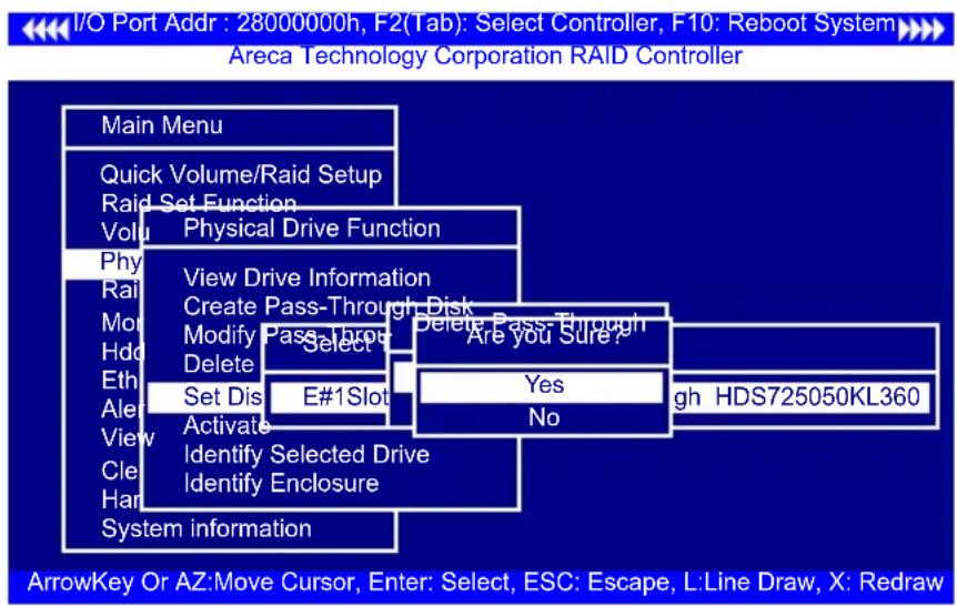
It sets a normal working disk as "failed" so that users can test some of the features and functions.
3.7.4.6 Activate Failed Disk
It forces the current “failed” disk in the system to be back on-line. “Activate Failed Disk” function has no effect on the removed disks, because a “removed” disk does not give the controller a chance to mark it as “failure”.

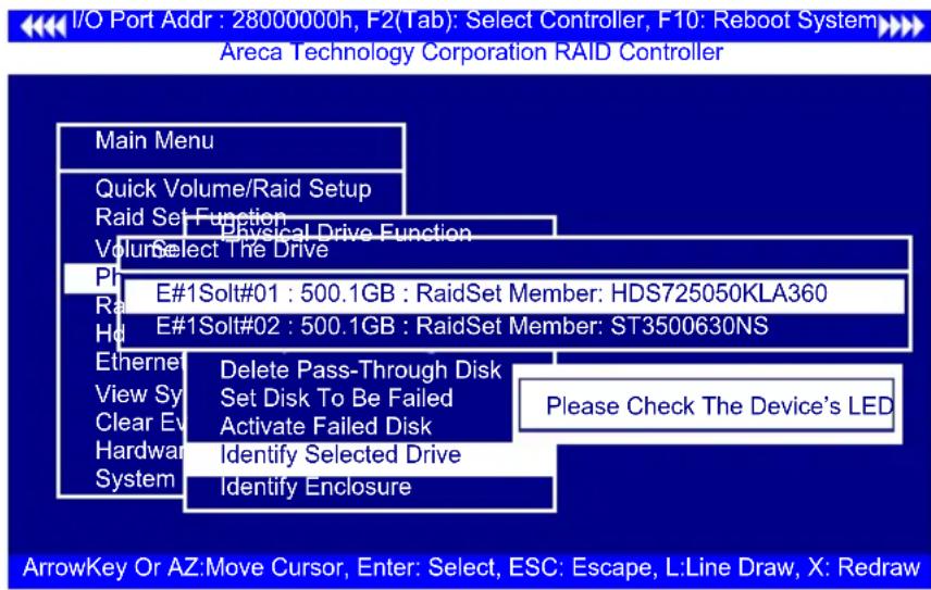
3.7.4.7 Identify Selected Drive
To prevent removing the wrong drive, the selected disk fault LED indicator will light for physically locating the selected disk when the "Identify Selected Device" is selected.
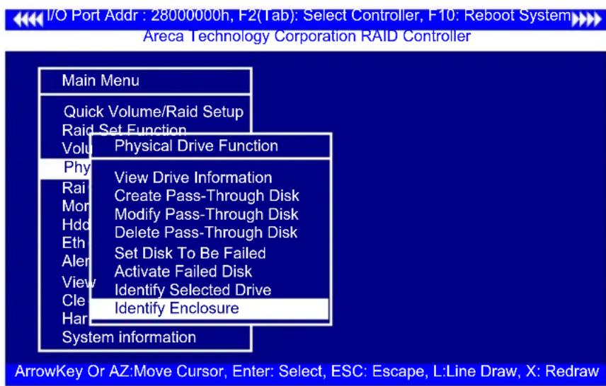
3.7.4.8 Identify Enclosure
To prevent removing the wrong enclosure, the selected Areca expander enclosure all disks fault LED indicator will light for physically locating the selected enclosure when the "Identify Enclosure" is selected. This function will also light the enclosure LED indicator, if it is existed.
3.7.5 Raid System Function
To set the "Raid System Function", move the cursor bar to the main menu and select the "Raid System Function" item and then press Enter key. The "Raid System Function" menu will show multiple items. Move the cursor bar to an item, then press Enter key to select the desired function.

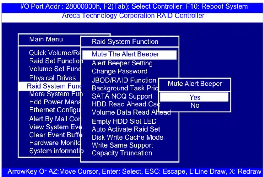
3.7.5.1 Mute The Alert Beeper
The "Mute The Alert Beeper" function item is used to control the SATA RAID controller beeper. Select Yes and press the Enter key in the dialog box to turn the beeper off temporarily. The beeper will still activate on the next event.
3.7.5.2 Alert Beeper Setting
The "Alert Beeper Setting" function item is used to "Disabled" or "Enabled" the SATA RAID controller alarm tone generator. Select "Disabled" and press the Enter key in the dialog box to turn the beeper off.

3.7.5.3 Change Password
The manufacture default password is set to 0000.
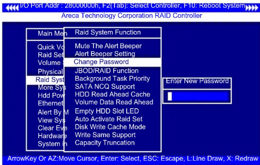
The password option allows user to set or clear the password protection feature. Once the password has been set, the user can monitor and configure the controller only by providing the correct password. This feature is used to protect the internal RAID system from unauthorized access. The controller will check the password only when entering the main menu from the initial screen. The system will automatically go back to the initial screen if it does not receive any command in 5 minutes.
To set or change the password, move the cursor to "Raid System Function" screen, press the "Change Password" item. The "Enter New Password" screen will appear. Do not use spaces when you enter the password. If spaces are used, it will lock out the user. To disable the password, only press Enter key in both the "Enter New Password" and "Re-Enter New Password" column. The existing password will be cleared. No password checking will occur when entering the main menu.
3.7.5.4 JBOD/RAID Function
JBOD is an acronym for "Just a Bunch Of Disk". A group of hard disks in a RAID box are not set up as any type of RAID configuration. All drives are available to the operating system as an individual disk. JBOD does not provide data redundancy. User needs to delete the RAID set, when you want to change the option from the RAID to the JBOD function.

3.7.5.5 Background Task Priority
The “Background Task Priority” is a relative indication of how much time the controller devotes to a rebuild operation. The 6Gb/s SATA RAID controller allows the user to choose the rebuild priority (UltraLow, Low, Normal, High) to balance volume set access and rebuild tasks appropriately.
I/O Port Addr : 28000000h, F2(Tab): Select Controller, F10: Reboot System Areca Technology Corporation RAID Controller
| Main Menu | Raid System Function | |
| Quick Volume/Ra | Mute The Alert Beeper | |
| Raid Set Function | Alert Beeper Setting | |
| Volume Set Func | Change Password | |
| Physical Drives | JBOD/RAID Function | |
| Raid System Func | Background Task Priority | |
| More System Fun | SATA NCQ Support | Background Task Priority |
| Hdd Power Mana | HDD Read Ahead C | |
| Ethernet Configur | Volume Data Read | UltraLow(5%) |
| Alert By Mail Con | Empty HDD Slot LE | Low(20%) |
| View System Eve | Auto Activate Raid S | Medium(50%) |
| Clear Event Buffer | Disk Write Cache M | High(80%) |
| Hardware Monito | Write Same Support | |
| System information | Capacity Truncation |
ArrowKey Or AZ:Move Cursor, Enter: Select, ESC: Escape, L:Line Draw, X: Redraw
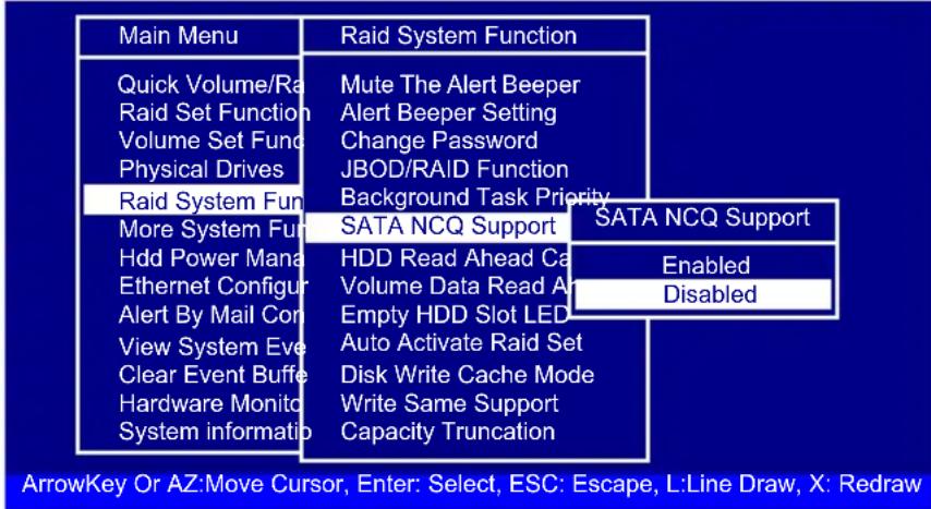
3.7.5.6 SATA NCQ Support
RAID controller supports both SATA and SATA disk drives. The SATA NCQ allows multiple commands to be outstanding within a drive at the same time. Drives that support NCQ have an internal queue where outstanding commands can be dynamically rescheduled or re-ordered, along with the necessary tracking mechanisms for outstanding and completed portions of the workload. The 6Gb/s SATA RAID controller allows the user to select the SATA NCQ support: "Enabled" or "Disabled".
I/O Port Addr : 28000000h, F2(Tab): Select Controller, F10: Reboot System Areca Technology Corporation RAID Controller
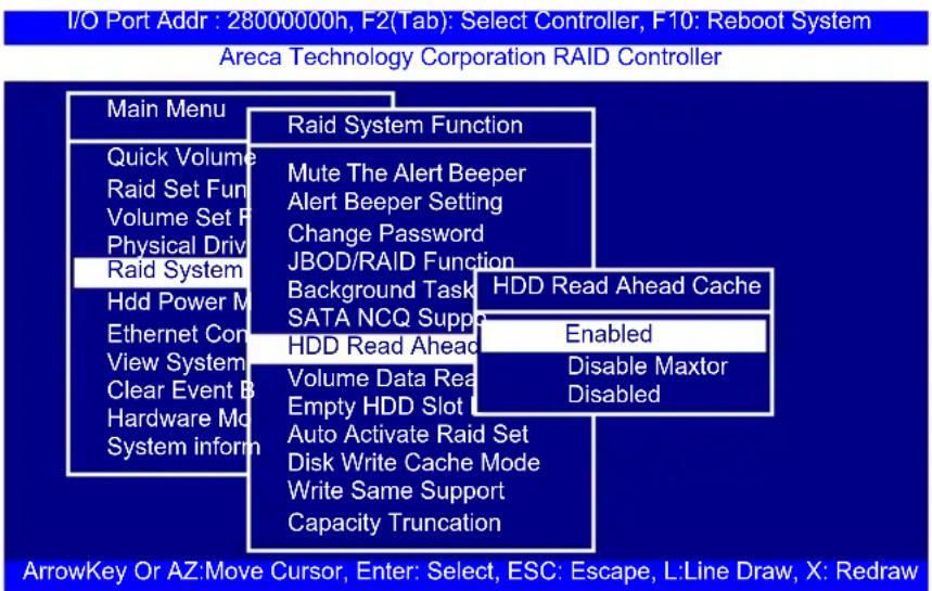
3.7.5.7 HDD Read Ahead Cache
Allow Read Ahead (Default: Enabled)—When "Enabled", the drive's read ahead cache algorithm is used, providing maximum performance under most circumstances.
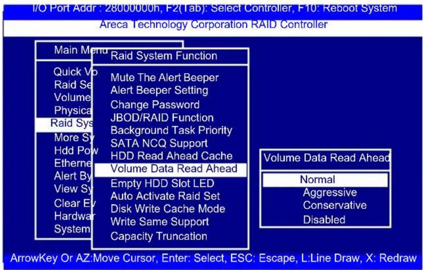
3.7.5.8 Volume Data Read Ahead
The volume read data ahead parameter specifies the controller firmware algorithms which process the read ahead data blocks from the disk. The "Volume Data Read Ahead" parameter is normal by default. To modify the value, you must set it from the "Raid System Function" using the 'Volume Data Read Ahead' option. The default "Normal" option satisfies the performance requirements for a typical volume. The "Disabled" value implies no read ahead. The most efficient value for the controllers depends on your application. The "Aggressive" value is optimal for sequential access but it degrades random access.
3.7.5.9 Empty HDD Slot LED
The firmware has added the "Empty HDD Slot LED" option to setup the fault LED light "ON" or "OFF" when there is no HDD installed. When each slot has a power LED for the HDD installed identify, user can set this option to "OFF". Choose option "ON", the 6Gb/s SATA RAID controller will light the fault LED; if no HDD installed.

3.7.5.10 Auto Activate Raid Set
When some of the disk drives are removed in power off state or boot up stage, the RAID set state will change to "Incomplete State". But if a user wants to automatically continue to work while the 6Gb/s SATA RAID controller is powered on, then user can set the "Auto Activate Raid Set" option to "Enabled". The RAID state will change to "Degraded Mode" while it powers on.
I/O Port Addr : 28000000h, F2(Tab): Select Controller, F10: Reboot System
Areca Technology Corporation RAID Controller
| Main Menu | Raid System Function | |
| Quick Volume | Mute The Alert Beeper | |
| Raid Set Fun | Alert Beeper Setting | |
| Volume Set F | Change Password | |
| Physical Driv | JBOD/RAID Function | |
| Raid System | Background Task Priority | |
| More System | SATA NCQ Support | |
| Hdd Power M | HDD Read A | Auto Activate Raid When Power on |
| Ethernet Cor | Volume Data | |
| Alert By Mail | Empty HDD | Disabled |
| View System | Auto Activate | Enabled |
| Clear Event B | Disk Write Cache Mode | |
| Hardware Mo | Write Same Support | |
| System inform | Capacity Truncation |
ArrowKey Or AZ:Move Cursor, Enter: Select, ESC: Escape, L:Line Draw, X: Redraw
3.7.5.11 Disk Write Cache Mode
User can set the "Disk Write Cache Mode" to Auto, Enabled, or Disabled. "Enabled" increases speed, "Disabled" increases reliability.
I/O Port Addr : 28000000h, F2(Tab): Select Controller, F10: Reboot System
Areca Technology Corporation RAID Controller
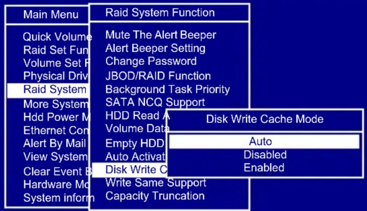
ArrowKey Or AZ:Move Cursor, Enter: Select, ESC: Escape, L:Line Draw, X: Redraw
3.7.5.12 Write Same Support
Drives that support the Write Same feature (SCT) can write to multiple drive sectors at once, improving initialization time. To take advantage of this feature, all the drives in the unit must support Write Same. User can set the "Enabled" or "Disabled" for the controller initialization.

3.7.5.13 Capacity Truncation
The 6Gb/s SATA RAID controller uses drive truncation so that drives from different vendors are more likely to be usable as spares for one another. Drive truncation slightly decreases the usable capacity of a drive that is used in redundant units. The controller provides three truncation modes in the system configuration: Multiples Of 10G, Multiples Of 1G and Disabled.
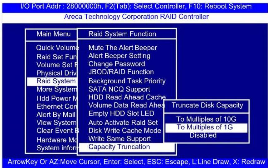
Multiples Of 10G: If you have 120 GB drives from different vendors; chances are that the capacity varies slightly. For example, one drive might be 123.5 GB, and the other 120 GB. "Multiples Of 10G" truncates the number under tens. This makes the same capacity for both of these drives so that one could replace the other.
Multiples Of 1G: If you have 123 GB drives from different vendors; chances are that the capacity varies slightly. For example, one drive might be 123.5 GB, and the other 123.4 GB. "Multiples Of 1G" truncates the fractional part. This makes the same capacity for both of these drives so that one could replace the other.
Disabled: It does not truncate the capacity.
3.7.6 More System Functions
To set the "More System Functions", move the cursor bar to the main menu and select the "More System Functions" item and then press Enter key. The "More System Functions" menu will show multiple items. Move the cursor bar to an item, then press Enter key to select the desired function.
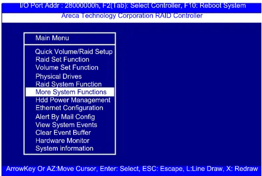
3.7.6.1 Smart Option For HDD
This option is used to increase the reliability of SSDs/HDDs by automatically copying data from a drive with potential to fail to a designated hot spare or newly inserted drive. The options are: "Failed The Drive", "Failed The Drive If Hot Sapre Exist", and "Alert Only". The default is "Alert Only".
"Failed The Drive"- controllers kill off the SMART fail drive immediately.
"Failed The Drive If Hot Sapre Exist" – controllers kill off the SMAT fail disk if hot sapre dive is existed.
"Alert Only" – it will trigger alert when there happens a SMART fail drive.

3.7.6.2 Smart Polling Interval
Besides the scheduled volume check, user can define the Smart Pulling Interval to pull the SMART status of each disk. The default is "on demand".
User can schedule every certain period of time interval to pull the SMART status of each disk. When SMART pulling is executed, disk activity will be temporally halted until the SMART parameter reading is finished. That is why you don't want to set the Interval too frequent. What to use is up to the users to decide based on their applications and experiment results.
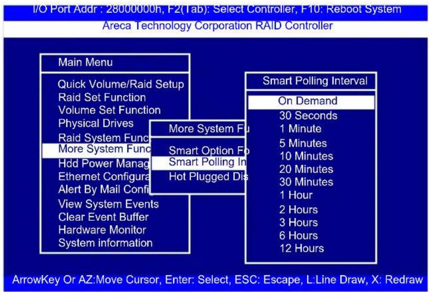
3.7.6.3 Hot Plugged Disk For Rebuilding
It defines if the RAID array volume should start rebuilding or not when detects a disk is inserted/re-inserted during online. The options are: "Blank Disk Only", "Always", and "Disable". The default is "Blank Disk Only".
"Blank Disk Only"-it will trigger the rebuilding if and only if the inserted disk has not been in the RAID array before, which has no RAID signature on it. So when a previously removed disk is self re-inserted, it won't trigger the degraded RAID array to rebuild, and so that the administrator has a chance to identify this mis-behaving disk and replaces it.
"Always" – it is what it was before. Whenever a disk is inserted/re-inserted whether new or previously existed, it always trigger a rebuilding for the Degraded RAID set/Volume.
"Disable" – it will not trigger rebuilding regardless what sort of disk plugging in. When "Disable" and/or "Blank Disk Only" is selected, the re-inserted/previously removed disk will be identified as a disk in a separate RAID set with duplicated RAIDset# and with all the rest of RAID members missing.

3.7.7 HDD Power Management
The 6Gb/s SATA RAID controller has automated the ability to manage HDD power based on usage patterns. The "HDD Power Management" allows you to choose a "Stagger Power On", "Low Power Idle", "Low RPM" and completely "Spins Down HDD". It is designed to reduce power consumption and heat generation on idle drives.
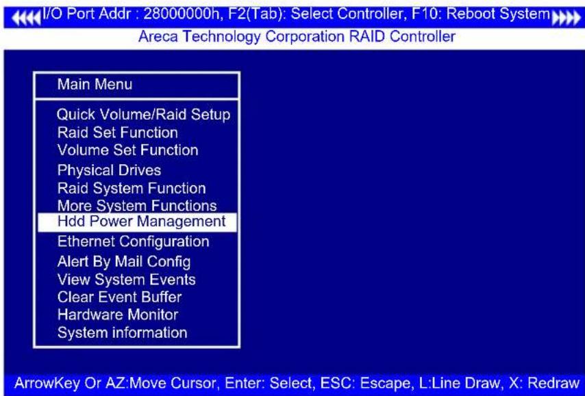
3.7.7.1 Stagger Power On
In a PC system with only one or two drives, the power can supply enough power to spin up both drives simultaneously. But in systems with more than two drives, the startup current from spinning up the drives all at once can overload the power supply, causing damage to the power supply, disk drives and other system components. This damage can be avoided by allowing the host to stagger spin-up of the drives. The SATA drives have supported the staggered spin-up capabilities to boost reliability. The staggered drive spin-up is a very useful feature for managing multiple disk drives in a storage subsystem. It gives the host the ability to spin up the disk drives sequentially or in groups, allowing the drives to come ready at the optimum time without straining the system power supply. The staggered drive spin-up in a multiple drive environment also avoids the extra cost of a power supply designed to meet short-term startup power demand as well as steady state conditions.
The 6Gb/s SATA RAID controller has included the option for customer to select the disk drives sequentially staggered power up value. The values can be selected from 0.4s to 6s per step which powers up one group of drives.

3.7.7.2 Time To Hdd Low Power Idle
This option delivers lower power consumption by automatically unloading recording heads during the setting idle time. The values can be selected "Disabled" or within the range 2 to 7 minutes.
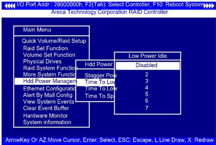
3.7.7.3 Time To Low RPM Mode
This function can automatically spin disks at lower RPM if there have not been used during the setting idle time. The values can be selected “Disabled” or within the range 10 to 60 minutes.

3.7.7.4 Time To Spin Down Idle Hdd
This function can automatically spin down the drive if it hasn't been accessed for a certain amount of time. This value is used by the drive to determine how long to wait (with no disk activity, before turning off the spindle motor to save power). The values can be selected "Disabled" or within the range 1 to 60 minutes.

3.7.8 Alert By Mail Config
To configure the 6Gb/s SATA RAID controller e-mail function, move the cursor bar to the main menu and click on the "Alert By Mail Config" link. The "Alert By Mail Config" menu will show all items. Move the cursor bar to the "Alert By Mail Config" item, then select the desired function.
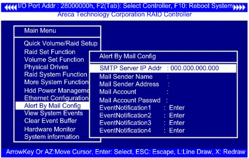
3.7.9 View System Events
To view the 6Gb/s SATA RAID controller's system events information, move the cursor bar to the main menu and select the "View System Events" link, then press the Enter key. The 6Gb/s SATA RAID controller's events screen appear.
Choose this option to view the system events information: Timer, Device, Event type, Elapsed Time, and Errors. The SATA RAID controller does not have a build-in real time clock. The time information is the relative time from the 6Gb/s SATA RAID controller powered on.
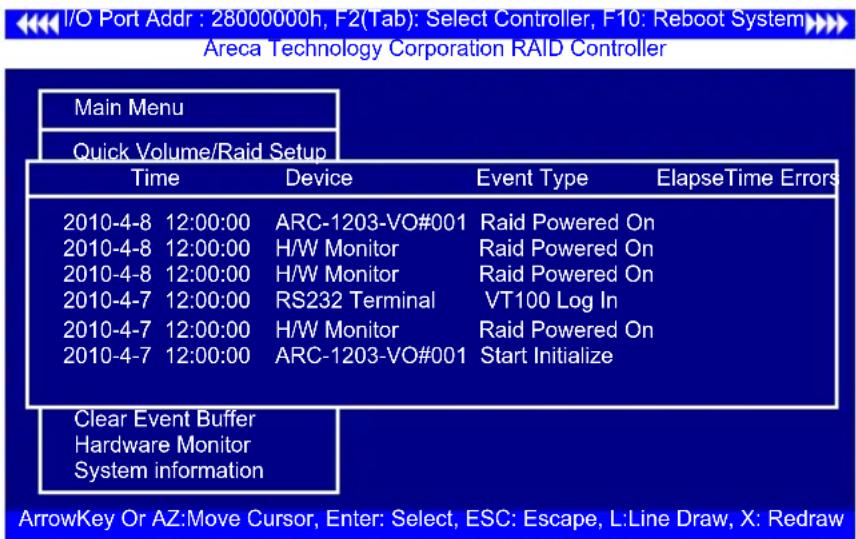
3.7.10 Clear Events Buffer
Use this feature to clear the entire events buffer.

3.7.11 Hardware Monitor
To view the RAID controller's hardware monitor information, move the cursor bar to the main menu and click the "Hardware Monitor" link. The "Controller H/W Monitor" screen appears. The "Controller H/W Monitor" provides the CPU temperature, controller temperature and voltage of the 6Gb/s SATA RAID controller.

3.7.12 System Information
Choose this option to display controller name, firmware version, BOOT ROM version, SATA firmware version, serial number, main processor, CPU instruction cache and data cache size, system memory, and current IP address. To check the system information, move the cursor bar to "System Information" item, then press Enter key. All relevant controller information will be displayed.
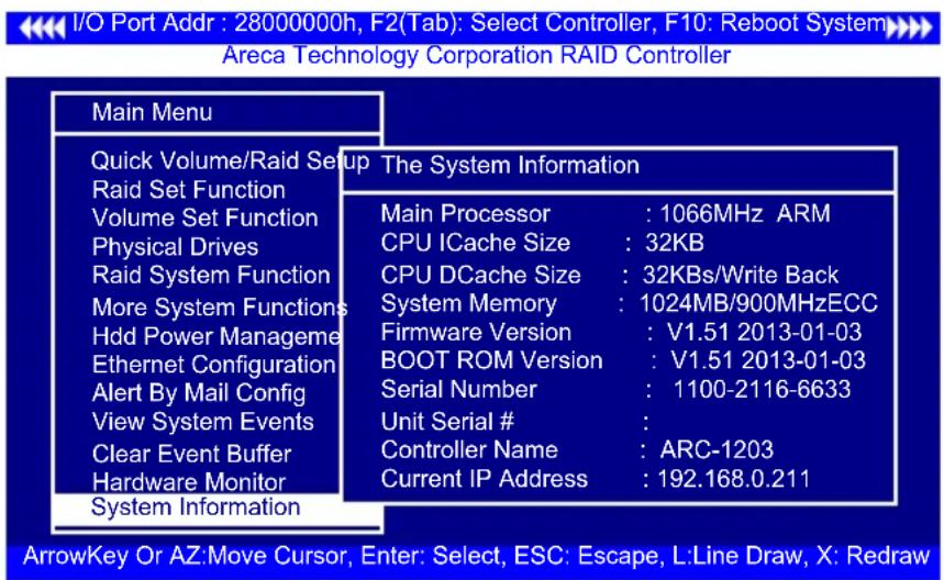
4. Driver Installation
This chapter describes how to install the SATA RAID controller driver to your operating system. The installation procedures use the following terminology:
Installing operating system on SATA controller's volume
If you have a new drive configuration without an operating system and want to install operating system on a disk drive managed by the SATA RAID controller. The driver installation is a part of the operating system installation.
Installing SATA RAID controller into an existing operating system
The computer has an existing operating system installed and the SATA RAID controller is being installed as a secondary controller.
Have all required system hardware and software components on hand before proceeding with the setup and installation. Materials required:
- Microsoft Windows, Linux, FreeBSD, Solaris and Mac OS X/macOS installation CD
- SATA RAID controller software CD
- SATA RAID controller
4.1 Creating the Driver Disk
The software CD disc shipped with the 6Gb/s RAID controller is included driver files for Windows, Linux, FreeBSD, Solaris and Mac OS X/macOS.
If you do not have the software CD disc with the package, contact your local dealers or you can also download the latest version drivers from Areca web site at http://www.areca.com.tw
These driver files are intended for use with new operating system installations. You can copy the driver file to USB device and installed from it. Determine the correct kernel version and identify
which files contain drivers for that kernel, and a screen with several choices will be displayed.
The driver disk is ready now. Proceed the following installation with the instructions for your operating system.
4.2 Driver Installation for Windows
The SATA RAID controller can be used with Microsoft Windows 10/8/Server 2012/7/2008/Vista/XP/2003 with StorPort Drivers.
4.2.1 Installing Windows on a RAID Volume
For completed details on installing Windows, see the Windows User's Manual. The following procedures detail installing the SATA RAID controller driver while installing Windows 10/8/Server 2012/7/2008/Vista/XP/2003. Have your bootable Microsoft Windows CD and follow the required procedure below to install SATA RAID controller:
- Make sure you follow the instructions in Chapter 2 "Hardware Installation" to install the controller and connect the disk drives or enclosure.
- Start the system and then press Tab or F6 to access the Mc BIOS RAID manager. Use the McBIOS RAID manager to create the RAID set and volume set to which you will install Windows. For details, see Chapter 3 "McBIOS RAID manager". Once a volume set is created and configured, continue with next step to install the operating system.
- Insert the Windows setup CD and reboot the system to begin the Windows installation.
- Follow the on-screen instructions to begin the Windows installation.
-
When prompted to specify a location for Windows, select "Load Driver".
-
Insert the USB driver disk or floppy drive, browse to the driver location, then click "OK".
- Window will check the floppy; select the correct card and CPU type for your hardware from the listing and press "Next" to install it.
- Click on "Next" again to accept the default partition configuration, or refer to your Windows documentation to configure partitions manually.
- From this point on, simply follow the Microsoft Windows installation procedure. Follow the on-screen instructions, responding as needed, to complete the installation.
- After the installation is completed, reboot the system to load the new driver/operating system.
- See Chapter 5 in this manual to customize your RAID volume sets using McRAID storage manager.
After you finish creating additional volume, the following steps show how to make any new volumes or independent disks accessible to Windows.
(a). Click "Start" = => right-click "Computer" and select "Manage".
(b). Click "Disk Management" in the left pane.
(c). Scroll down to the bottom of the middle pane. Windows will display a list of new drives attached to your system with a label such as "Disk 1" or "Disk 2", etc.
(d). Right-click on the drive you want to partition and then again to format it
(e). Once it's formatted, Windows automatically assigns the next available drive letter to it and then it will appear in Windows Explorer.
4.2.2 Installing Controller on an Existing Windows
In this scenario, you are installing the controller in an existing Windows system. To install the driver:
- Follow the instructions in Chapter 2, the Hardware Installation Chapter, to install the controller and connect the disk drives or enclosure.
- Start the system and then press Tab or F6 to enter the controller McBIOS RAID manager. Use the configuration utility to create the RAID set and volume set. For details, see Chapter 3, McBIOS RAID Manager. Once a volume set is created and configured, continue with installation of the driver.
- Re-Boot Windows and the OS will recognize the SATA RAID controller and launch the "Found New Hardware Wizard", this guides you in installing the SATA RAID driver.
- The Windows will pop-up and provide a choice of how to proceed. so that you can choose a specific driver.
- When the next screen queries the user about utilizing the currently installed driver, click on the "Have Disk" button.
- Insert the SATA RAID controller driver media to locate the correct path. Click on the "Next" button.
- Windows automatically copies the appropriate driver files and rebuilds its driver database.
- The summary screen appears; click on the "close" button.
- Restart the computer to load the new drivers.
- See Chapter 5 in this manual for information on customizing your RAID volumes using McRAID storage manager.
After you finish creating additional volume, the following steps show how to make any new volumes or independent disks acces-
sible to Windows.
(a). Click "Start" = => right-click "Computer" and select "Manage".
(b). Click "Disk Management" in the left pane.
(c). Scroll down to the bottom of the middle pane. Windows will display a list of new drives attached to your your system with a label such as "Disk 1" or "Disk 2", etc.
(d). Right-click on the drive you want to partition and then again to format it
(e). Once it's formatted, Windows automatically assigns the next available drive letter to it and then it will appear in Windows Explorer.
4.2.3 Uninstall controller from Windows
To remove the SATA RAID controller driver from the Windows system, follow the instructions below.
- Ensure that you have closed all applications and are logged in with administrative rights.
- Open "Control Panel" and start the "Add/Remove Program" icon and uninstall and software for the SATA RAID controller.
- Go to "Control Panel" and select "System". Select the "Hardware" tab and then click the "Device Manager" button. In device manager, expand the "SCSI and RAID Controllers" section. Right click on the SATA RAID controller and select "Uninstall".
- Click Yes to confirm removing the SATA RAID driver. The prompt to restart the system will then be displayed.
4.3 Driver Installation for Linux
This chapter describes how to install the SATA RAID controller driver to Red Hat Linux, SuSE and other versions of Linux. Before installing the SATA RAID driver to the Linux, complete the following actions:
- Install and configure the controller and hard disk drives according to the instructions in Chapter 2 Hardware Installation.
- Start the system and then press Tab or F6 to enter the McBIOS RAID manager configuration utility. Using the McBIOS RAID manager to create the RAID set and volume set. For details, see Chapter 3, McBIOS RAID Manager.
If you are using a Linux distribution for which there is not a compiled driver available from Areca, you can copy the source from the SAS software CD or download the source from the Areca website and compile a new driver.
Compiled and tested drivers for Red Hat and SuSE Linux are included on the shipped CD. You can download updated versions of compiled and tested drivers for RedHat or SuSE Linux from the Areca web site at http://www.areca.com.tw. Included in these downloads is the Linux driver source, which can be used to compile the updated version driver for RedHat, SuSE and other versions of Linux. Please refer to the "readme.txt" file on the included SATA RAID controller CD or website to make driver diskette and install driver to the system.
4.4 Driver Installation for FreeBSD
This chapter describes how to install the SATA RAID controller driver to FreeBSD. Before installing the SATA RAID driver to FreeBSD, complete following actions:
- Install and configure the controller and hard disk drives according to the instructions in Chapter 2, Hardware Installation.
- Start the system and then press Tab or F6 to enter the McBIOS RAID Manager configuration utility. Use the McBIOS RAID man-
ager to create the RAID set and volume set. For details, see Chapter 3, McBIOS RAID Manager.
The supplied software CD that came with the SATA RAID controller includes compiled and tested drivers for FreeBSD 7.x (7.2 and onwards), 8.x (8.0 and onwards) and 9.x (9.0 and onwards). To check if a more current version driver is available, please see the Areca web site at http://www.areca.com.tw.
Please refer to the "readme.txt" file on the SATA RAID controller software CD or website to make driver diskette and install driver to the system.
4.5 Driver Installation for Solaris
This chapter describes how to install the SATA RAID controller driver to Solaris. Before installing the SATA RAID driver to Solaris, complete following actions:
- Install and configure the controller and hard disk drives according to the instructions in Chapter 2, Hardware Installation.
- Start the system and then press Tab or F6 to enter the McBIOS RAID Manager configuration utility. Use the McBIOS RAID manager to create the RAID set and volume set. For details, see Chapter 3, McBIOS RAID Manager.
The supplied software CD that came with the SATA RAID controller includes compiled and tested drivers for Solaris 10/11 x86/x86_64. Please refer to the "readme.txt" file on the software CD or website: http://www.areca.com.tw to make driver diskette and install driver to the system.
4.6 Driver Installation for Mac X
After hardware installation, the SATA disk drives connected to the SATA RAID controller must be configured and the volume set units initialized by the controller before they are ready to use by the system.
4.6.1 Installation Procedures
This section describes detailed instructions for installing the Areca Mac driver & utility for the 6Gb/s SATA RAID controller on your Intel_based Mac Pro. You must have administrative level permissions to install Mac driver & utility. You can use the MRAID installer to install Mac driver & utility (MRAID) at once or "Custom" to install special components.
To follow the process to install driver & utility on Intel-based Mac as below:
- Insert the Areca Software CD that came with your Areca SATA RAID controller.
- Double-click on the "install_mraid.zip" file that resides at
\packages\MacOS to add the installer on the Finder. - Launch the installer by double-clicking the install_mraid on the Finder.
- Follow the installer on-screen steps, responding as needed, to complete the Areca driver and MRAID (ArcHTTP and CLI utility) installation.
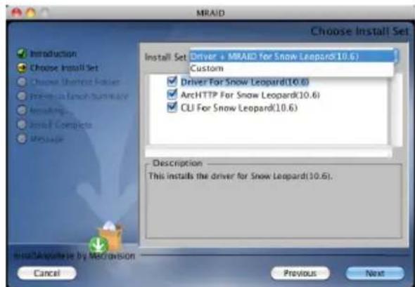
- Driver is required for the operating system to be able to interact with the Areca RAID controller.
Important:
Be sure to update the ArcMSR.kext driver shipping with Mac OS X to V1.3.7 or later from the software CD or from the Areca website.
- ArcHTTP has to be installed for GUI RAID console (MRAID storage manager) to run. It also runs as a service or daemon in the background that allows capturing of events for mail and SNMP traps notification. Refer to the section 5.6 ArcHTTP Configuration, for details about the mail and SNMP traps configuration.
- Command Line Interface (CLI) lets you set up and manage RAID controller through a command line interface. CLI performs many tasks at the command line. You can download CLI manual from Areca website or software CD
-
A reboot is required to complete the installation (This will start the ArcHTTP so RAID Console can be used).
-
Normally ArcHTTP64 and CLI are installed at the same time on SATA RAID controller. Once ArcHTTP and CLI have been installed, the ArcHTTP background task automatically starts each time when you start your computer.
There is one "MRAID" icon showing on your desktop. Double-click on the "MRAID" icon to locate your ArcHTTP utility and CLI program file folder.

When you double-click on the "ArcHTTP64", it shows all RAID storages available on the system and create an individual RAID storage icon located on left column of the "ArcHTTP Configurations" screen.

Locate "ARC-1203 Web Management" and launch the selected McRAID storage manager. Enter RAID storage default User Name "admin" and the Password "0000" when the login page prompted for it. After logging in, the McRAID storage manager process starts.
If there is any RAID adapter missed on the system start-up, you can use the "Rescan Device" function. See chapter 5 in this manual for information on customizing your RAID volumes using McRAID storage manager.
4.6.2 Making Volume Sets Available to Mac OS X
When you create a volume through McRAID storage manager, the Mac OS X recognizes that a new disk is avail, and displays a message asking what you next want to do. If the message does not show up, start the "Disk Utility" manually from the "Finder", use the "Go" menu and open the "Utilities" folder. Double-click on the "Disk Utility" program. Follow the on-screen prompts to create a volume set and to assign a disk drive letter.
To initialize and partition your unit
-
When the Disk Utility window opens, find and select the desired drive in the sidebar that represents your RAID storage and click on the "Partition" button.
-
In the Partition Layout column, click on the "Current" to show the drop-down menu and select the number of partitions that you want your RAID storage to have. Each partition will appear as a separate drive on your computer.
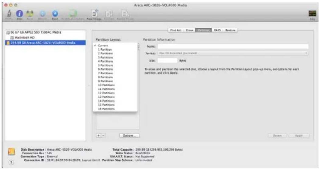
- Specify your Partition Information, Option setting and click on the "Apply" button.

If you're not sure which format to use, choose Mac OS X Extended (Journaled).
- When a message asks you to confirm you want to partition the disk, click on the "Partition" button. This may take a couple of minutes, depending on the size of the drives in your RAID storage. When the partitioning is complete, icons for each new partition show up on your desktop. They are now ready to use.
5. ArcHTTP Proxy Server Installation
Overview
After hardware installation, the SATA disk drives connected to the SATA RAID controller must be configured and the volume set units initialized before they are ready to use.
The user interface for these tasks can be accessed through the built-in configuration that resides in the controller's firmware. It provides complete control and management of the controller and disk arrays, eliminating the need for additional hardware or software.
In addition, a software utility to configure the SATA RAID controller is provided on the software CD delivered with SATA RAID controller. This software CD contains the software utility that can monitor, test, and support the SATA RAID controller. The software utility and McRAID storage manager can configure and monitor the SATA RAID controller via ArcHTTP proxy server interface. The following table outlines their functions:
| Configuration Utility Operating System Supported | |
| McBIOS RAID Manager OS-Independent | |
| McRAID Storage Manager(Via ArcHTTP proxy server) | Windows, Linux, FreeBSD, Solaris and Mac OS X |
| SAP Monitor (Single Admin Portal to scan for multiple RAID units in the network, Via ArcHTTP proxy server) | Windows |
The HTTP management software (ArcHTTP) runs as a service or daemon, and have it automatically start the proxy for all controllers found. This way the controller can be managed remotely without having to sign in the server. The HTTP management software (ArcHTTP) also has integrated the email notification and SNMP extension agent. The email notification can be configured in local or remote standard web browser.
5.1 For Windows
You must have administrative level permissions to install SATA RAID software. This procedure assumes that the SATA RAID hardware and Windows are installed and operational in your system.
Screen captures in this section are taken from a Windows XP installation. If you are running another version of Windows, your installation screen may look different, but the ArcHTTP proxy server installation is essentially the same.
-
Insert the RAID controller software CD in the CD-ROM drive.
-
Run the install.exe file that resides at:
\PACKAGES\Windows\http directory on the CD-ROM. -
The screen shows ArcHTTP installation introduction.
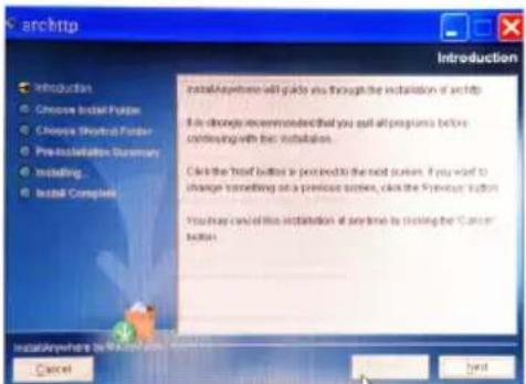
Follow the on-screen prompts to complete ArcHTTP proxy server software installation. A program bar appears that measures the progress of the ArcHTTP proxy server setup. When this screen completes, you have completed the ArcHTTP proxy server software setup.
- After a successful installation, press "Done" to quit the install-er.

There "Areca RAID Controller" icon bar window start appearing in the taskbar, double-click to launch the ArcHTTP Configuration screen. Or click on the "Start" button in the Windows task bar and then click on the "Program", select the "McRAID" and run "ArcHTTP proxy server". The ArcHTTP Configurations dialog box appears.

It shows all RAID adapters available on the system and creates an individual adapter icon located on left column of the "ArcHTTP Configurations" screen. This adapter icon is for user to launch the selected RAID adapter web browser RAID manager.
-
See the next chapter detailing the McRAID Storage Manager to customize your RAID volume set.
-
If you need to configure the "System Function" of ArcHTTP, please refer to section 5.6 ArcHTTP Configuration.
5.2 For Linux
You should have administrative level permissions to install SATA RAID software. This procedure assumes that the SATA RAID hardware and Linux are installed and operational in your system.
The following installation procedure explains how to install the SATA RAID software for Linux. The ArcHTTP proxy server is provided on the software CD delivered with SATA RAID controller card or download from the www.areca.com.tw. The firmware embedded McRAID storage manager can configure and monitor the SATA RAID controller via ArcHTTP proxy server.
- Login as root. Copy the ArcHTTP file to a local directory.
(a). Insert the SATA RAID controller CD in the CD-ROM drive.
(b). Copy
(c). Download from the www.areca.com.tw or from the email attachment.
- You must have administrative level permissions to install SATA RAID controller ArcHTTP proxy server software. This procedure assumes that the SATA RAID hardware and driver are installed and operational in your system.
The following details are the installation procedure of the SATA RAID controller for Linux ArcHTTP proxy server software.
(a). Run the ArcHTTP proxy server by using the following command:
Usage: ./archttp32 (TCP_PORT) or ./archttp64 (TCP_PORT). It depends on your OS version.
Parameters: TCP_PORT value= 1\~65535 (If TCP_PORT assigned, ArcHTTP will start from this port. Otherwise, it will use the setting in the archttpsrv.conf or default 81). This is the port address assigning for the ArcHTTP configuration (Cfg Assistant). Such as: archttp64 1553
(b). ArcHTTP server console started, Controller card detected then ArcHTTP proxy server screen appears.
Copyright (c) 2004 Areca, Inc. All Rights Reserved.
Areca HTTP proxy server V2.4.0 for Areca RAID controllers.
Controller(s) list
Cfg Assistant : Listen to port[1553].
Controller1 : Listen to port[1554].
Binding IP:[0.0.0.0]
Note: IP[0.0.0.0] stands for any ip bound to this host.
# # # # # # # # # # # # # # # # # # # # # # # # # # # # #
Press CTRL-C to exit program!!
# # # # # # # # # # # # # # # # # # # # # # # # # # # #
Controller [1] Http: New client [9] accepted
Controller [1] Http: New Recv 243 bytes
Controller [1] Http: Send [174] bytes back to the client
(c). If you need the "Cfg Assistant", please refer to section 5.6 ArcHTTP Configuration.
(d). For detailing about McRAID storage manager to customize your RAID volume set is discussed in Chapter 6.
For Mozilla user:
Because our management need Java support, so user may need upgrade to version 1.6 or later.
5.3 For FreeBSD
You must have administrative level permissions to install SATA RAID software. This procedure assumes that the SATA RAID hardware and FreeBSD are installed and operational in your system. The following installation procedure explains how to install the SATA RAID software for FreeBSD.
- Insert the SATA RAID controller software CD in the CD-ROM drive.
- Login as root. Copy
\PACKAGES\FreeBSD\http ArcHTTP file to a local directory. The next steps are same as Linux. Please see section 5.2 For Linux.
5.4 For Solaris 10
You must have administrative level permissions to install SATA RAID software. This procedure assumes that the SATA RAID hardware and Solaris are installed and operational in your system. The following installation procedure explains how to install the SATA RAID software for Solaris.
- Insert the SATA RAID controller software CD in the CD-ROM drive.
- Login as root. Copy
\PACKAGES\Solaris=http ArcHTTP file to a local directory. The next steps are same as Linux. Please see section 5.2 For Linux.
5.5 For Mac OS X
The firmware embedded McRAID storage manager can configure and monitor the SATA RAID controller via ArcHTTP proxy server. The ArcHTTP proxy server for Mac OS X has combined with the CLI and driver on the install_mraid installer, please refer to Chapter 4.6 Driver Installation for Mac OS X.
5.6 ArcHTTP Configuration
The ArcHTTP proxy server will automatically assign one additional port for setup its configuration. If you want to change the "archttpsrv.conf" setting up of ArcHTTP proxy server configuration, for example: General Configuration, Mail Configuration, and SNMP Configuration, please start Web Browser http:\localhost: Cfg Assistant. Such as http:\localhost: 81. The port number for the first controller McRAID storage manager is ArcHTTP proxy server configuration port number plus 1.

- General Configuration:
Binding IP: Restrict ArcHTTP proxy server to bind only single interface (If more than one physical network in the server).
HTTP Port#: Value 1\~65535.
Display HTTP Connection Information To Console: Select "Yes" to show Http send bytes and receive bytes information in the console.
Scanning PCI Device: Select "Yes" for ARC-1XXX series controller.
Scanning RS-232 Device: No.
Scanning Inband Device: No.
- Mail (alert by Mail) Configuration:
Many users require that email notifications be sent to the appropriate administrators when an alert is detected. To set up your mail servers, click on the "Mail Configuration" link. The "SMTP Server Configurations" allows you to define settings for your mail server. This setup screen is shown as below:

The following article describes a best practice methodology for setting this up in the "SMTP Server Configurations".
1. SMTP Server Configuration:
SMTP Server IP Address: Enter IP address of the SMTP server to configure your mail program correctly.
Ex: 192.168.0.2.
2. Mail Address Configurations:
Sender Name: This is the sender name that the e-mail alerts will appear to be coming from.
Ex: RaidController_1.
Mail address: This is the mail address that the e-mail alerts will appear to be coming from, but don't type IP to replace domain name.
Ex: RaidController_1@areca.com.tw.
Account: Enter the valid account if your SMTP mail server requires authentication.
Password: Enter the valid password if your SMTP mail server requires authentication.
3. Event Notification Configurations:
This step involves setting up of notification rules. Notification rules instruct ArcHTTP on the notifications that should be sent when certain types of alerts are detected.
MailTo Name: Enter the alert receiver name that will be shown in the outgoing mail.
Mail Address: Enter the receiver's e-mail address. This is the address you want the e-mail alerts sent to.
Ex: admin@areca.com.tw.
According to your requirement, set the corresponding event level:
Disable Event Notification: No event notification will be sent. Urgent Error Notification: Send only urgent events.
Serious Error Notification: Send urgent and serious events.
Warning Error Notification: Send urgent, serious and warning events.
Information Notification: Send all events.
Notification For No Event: Notify user if no event occurs within 24 hours.
• SNMP Traps Configuration:
This section discusses how to enable the SNMP traps on your RAID storage, and how to control the sending of SNMP traps from the ArcHTTP. To send the SNMP traps to client SNMP manager such as Net-SNMP manager using the IP address assigned to the operating system, you can simply use the SNMP function on the ArcHTTP. The ArcHTTP only provides one direction to send the trap to the SNMP manager without needing to install the SNMP extension agent on the host. If SNMP manager requests to query the SNMP information from RAID storage, please refer the Appendix D "SNMP Operation & Installation".
To set up SNMP traps sending function, click on the "SNMP Configuration" link. SNMP Traps Configurations are set up on this page. This setup screen is shown as below:
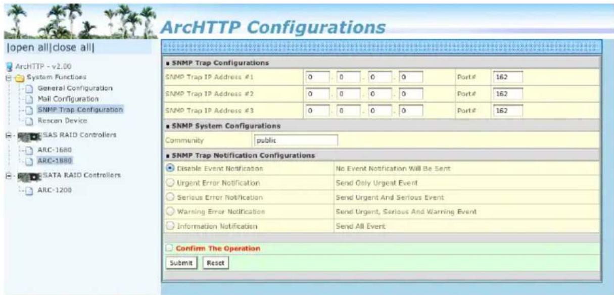
The following article describes a best practice methodology for setting this up in the "SNMP Traps Configurations".
1. SNMP Trap Configurations
Enter the SNMP trap IP address.
2. SNMP System Configurations
Community name acts as a password to screen accesses to the SNMP agent of a particular network device. Type the community names of the SNMP agent in this field. Most network devices use "public" as default of their community names. This value is case-sensitive.
3. SNMP Trap Notification Configurations
Event Notification Table refers to Appendix E. Before the client side SNMP manager application accepts the RAID storage traps, it is necessary to integrate the MIB into the management application's database of events and status indicator codes. Ensure the compilation process successfully integrates the contents of the areca_sata.mib file into the traps database. Please refer to Appendix D of "SNMP Operation & Installation". The MIBs file resides at:
Note:
After you confirm and submit configurations, you can use "Generate Test Event" feature to make sure these settings are correct.
- Rescan Device Configuration:
The ArcHTTP scans the RAID controllers on the system and creates an individual RAID controller icon located on left column of the "ArcHTTP Configurations" screen. If any RAID controller is missed at system start-up, then you can use the "Rescan Device" function to rescan the targets to allow a missed RAID storage to be added.

• Collect Support Data:
The "Collect Support Data" option on the ArcHTTP is used to download all controller's information (system information, configuration, disk information and event log) to a supported file (file name:ctlrxx-xxxxx.log). It will be automatically started when ERROR or SERIOUS event has occurred.
![ArcHTTP Configurations [open all|close all] Arch-HTTP - v2.2.0 System Functions General Configuration Mail Configuration SNMP Trap Configuration Rescan Device Collect Support Data SAS RAID Controllers ARC-1880 SATA RAID Controllers Do You Want To Collect Support Data? Confirm The Operation Submit Re…](/content/2026/05/990737/images/8cd4c74e68536bfd39879667e82c98beed7119f81fc86c552b3da12cfe816e32.jpg)
6. Web Browser-based Configuration
Before using the firmware-based browser McRAID storage manager, do the initial setup and installation of this product. If you need to boot up the operating system from a RAID volume set, you must first create a RAID volume by using McBIOS RAID manager. Please refer to section 3.3 Using Quick Volume /Raid Setup Configuration for information on creating this initial volume set.
The McRAID storage manager is firmware-based utility, which is accessible via the web browser installed on your operating system. The web browser-based McRAID storage manager is a HTML-based application, which utilizes the browser (IE, Chrome and Mozilla etc.) installed on your monitor station.
It can be accessed through the in-band PCIe bus. ArcHTTP is used to launch the in-band web browser-based McRAID storage manager. Use the McRAID storage manager to:
- Create RAID set
- Expand RAID set
- Define volume set
- Add physical drive
- Modify volume set
- Modify RAID level/stripe size
- Define pass-through disk drives
- Modify system function
- Update firmware
- Designate drives as hot spares
6.1 Start-up McRAID Storage Manager
With McRAID storage manager, you can:
- Locally manage a system containing a supported RAID storage that has Windows or Mac OS X, ArcHTTP and a supported browser.
- Remote and managed systems must have a TCP/IP connection.
- Start-up from Windows/Mac Local Administration
Once ArcHTTP and CLI have been installed, the ArcHTTP - back ground task automatically starts each time when you start your computer. There is one MARID icon showing on your "Desktop" or "Start" menu. This icon is for you to start up the ArcHTTP (launch the McRAID storage manager) and CLI utility. When you click on the ArcHTTP from MRAID icon, it shows all RAID controllers available on the host system and create an individual RAID controller icon located on left column of the "ArcHTTP Configurations" screen. This RAID controller icon is for user to launch the selected RAID controller web browser McRAID storage manager.
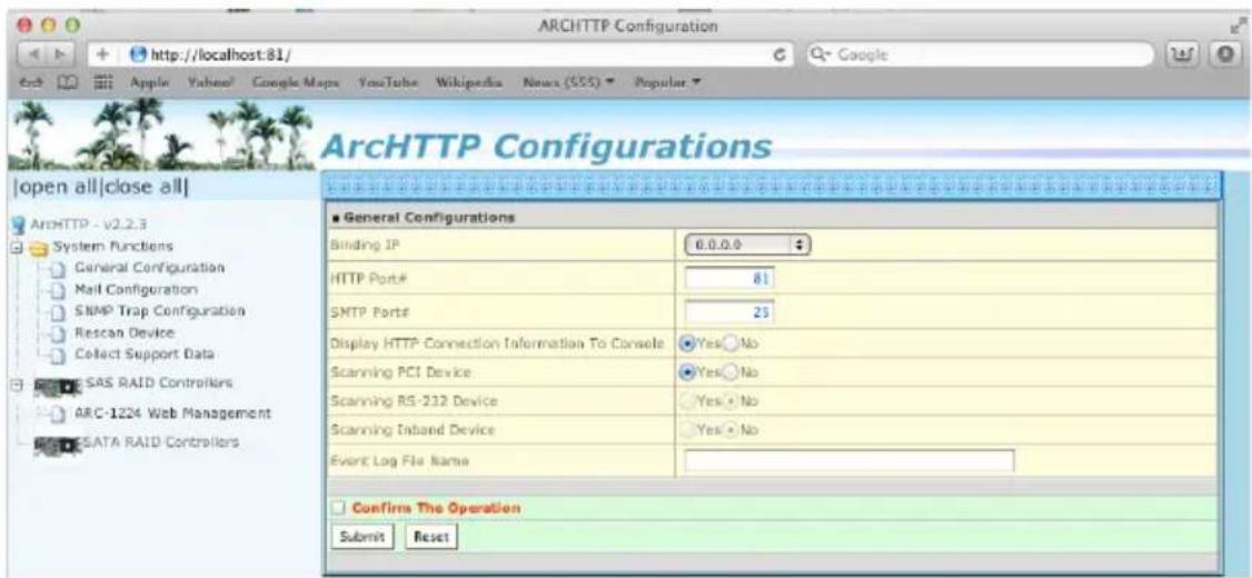
The "Enter Network Password" dialog screen appears, type the User Name and Password. The RAID controller default User Name is "admin" and the Password is "0000". After entering the user name and password, press Enter key to access the McRAID storage manager.
- Start-up from Local Administration
To configure the internal SATA RAID controller. You need to know its IP address. You can find the IP address assigned by the ArcHTTP proxy server installation: Binding IP:[X.X.X.X] and controller listen port.
- You can click on the individual adapter icon located on left column of the "ArcHTTP Configurations" screen or Launch
your McRAID storage manager by entering http://[Computer IP Address]:[Port Number] in the web browser.
- When connection is established, the "System Login" screen appears. The SATA RAID controller default user name is "admin" and the password is "0000".
6.2 McRAID Storage Manager
The following login screen is displayed in the browser. This screen displays the initial start-up configuration.

The RaidSet Hierarchy displays the "Raid Set List", "Volume Set List", and "Physical Disk List". The RAID set information, volume set information, and drive information can also be viewed by clicking on the "RAID Set Hierarchy" on the main menu screen.
- To display RAID set information, move the mouse cursor to the desired RAID set number, then click on it. The RAID set information will be displayed.
- To display volume set information, move the mouse cursor to the desired volume set number, then click on it. The volume set information will be displayed.
- To display drive information, move the mouse cursor to the desired physical drive number, then click on it. The drive information will be displayed.
6.3 Main Menu
The main menu shows all available functions, accessible by clicking on the appropriate link.
| Individual Category Description | |
| Quick Function Create a default configuration, which is based on the number of physical disks installed; it can modify the volume set Capacity, Raid Level, and Stripe Size. | |
| Raid Set Functions Create a customized RAID set. | |
| Volume Set Functions Create customized volume sets and modify the existed volume sets parameter. | |
| Physical Drives Create pass through disks and modify the existing pass through drives parameters. Also provides the function to identify disk drives (blinking fault LED). | |
| System Controls Setting the RAID system configuration. | |
| Information Viewing the controller information. The Raid Set Hierarchy can be viewed through the “Raid Set Hierarchy” item. |
6.4 Quick Function
![Areca Technology Corporation [open all|close all] Raid System Console Quick Function Quick Create RAID Set Functions Volume Set Functions Security Functions Physical Drives System Controls Information ■ Quick Create Raid/Volume Set Total Number Of Docks 2 Select Raid Level Raid 0 Maximum Capacity Al…](/content/2026/05/990737/images/3955e5c47c5c2efe67b05debd28244d0d9d3ccf5d7789cb9710d563f985816c7.jpg)
The number of physical drives in the 6Gb/s SATA RAID controller determines the Raid Levels that can be implemented with the RAID set. You can create a RAID set associated with exactly one volume set. The user can change the Raid Level, Capacity, Initialization Mode and Stripe Size. A hot spare option is also created, depending on the exist configuration. Click the "Confirm The Operation" check box and click on the "Submit" button in the "Quick Create" screen, the RAID set and volume set will start to initialize.
Note:
In "Quick Create", your volume set is automatically configured based on the number of disks in your system. Use the "Raid Set Functions" and "Volume Set Functions" if you prefer to customize your volume set.
6.5 Raid Set Functions
Use the "Raid Set Function" and "Volume Set Function" if you prefer to customize your volume set. Manual configuration can provide full control of the RAID set settings, but it will take longer to complete than the "Quick Volume/Raid Setup" configuration. Select the "Raid Set Function" to manually configure the RAID set for the first time or delete and reconfigure existing RAID sets. (A RAID set is a group of disks containing one or more volume sets.)
6.5.1 Create Raid Set
To create a RAID set, click on the "Create Raid Set" link. A "Select The Drive For RAID Set" screen is displayed showing the drive(s) connected to the current controller and enclosures. Click on the selected physical drives within the current RAID set. Enter 1 to 15 alphanumeric characters to define a unique identifier for a RAID set. The default RAID set name will always appear as "Raid Set #". Click the "Confirm The Operation" check box and click on the "Submit" button on the screen; the RAID set will start to initialize. If you have available disk member, you can repeat above procedures to define another RAID sets.
![Areca Technology Corporation [open all [close all]] Raid System Console Quick Function RAID Set Functions Create RAID Set Delete RAID Set Expand RAID Set Offline RAID Set Rename RAID Set Activate Incomplete RAID Set Create Hot Spare Delete Hot Spare Rescue RAID Set Volume Set Functions Security Func…](/content/2026/05/990737/images/58e59c5a3f12980ef0e01498ce9722f8595de7f9c01b2b433949a9e098e320d2.jpg)
128 volumes is the default mode for SATA RAID controller, the 16 volumes mode is used for support roaming this raidset to 3Gb/s SATA RAID controllers. The 3Gb/s SATA RAID controller is designed to support up to 16 volumes only. You have to use "Max 16 volumes" on the raidset mode if you plan to roam this raidset between 6Gb/s SATA RAID controller and 3Gb/s SATA RAID controller.
6.5.2 Delete Raid Set
To delete a RAID set, click on the "Deleted Raid Set" link. A "Select The RAID Set To Delete" screen is displayed showing all exist RAID sets in the current controller. Click the RAID set number which you want to delete in the select column on the delete screen. Then, click the "Confirm The Operation" check box and click on the "Submit" button in the screen to delete it. The volume sets included in the "Delete RAID Set". It will be deleted by this action.

6.5.3 Expand Raid Set
Instead of deleting a RAID set and recreating it with additional disk drives, the "Expand Raid Set" function allows the users to add disk drives to the RAID set that have already been created.
To expand a RAID set:
Select the "Expand Raid Set" option. If there is an available disk, then the "Select SATA Drives For Raid Set Expansion" screen appears.
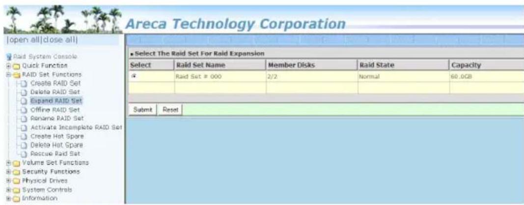
Select the target RAID set by clicking on the appropriate radio button. Select the target disk by clicking on the appropriate check box. Click on the "Submit" button to start the expansion on the RAID set. The new additional capacity can be utilized by one or more volume sets. The volume sets associated with this RAID set appear for you to have chance to modify RAID level or stripe size. Follow the instruction presented in the "Modify Volume Set" to modify the volume sets; operation system specific utilities may be required to expand operating system partitions.
Note:
- Once the "Expand Raid Set" process has started, user can not stop it. The process must be completed.
- If a disk drive fails during RAID set expansion and a hot spare is available, an auto rebuild operation will occur after the RAID set expansion completes.
- RAID set expansion is a quite critical process, we strongly recommend customer backup data before expand. Unexpected accident may cause serious data corruption.
6.5.4 Offline Raid Set
This function is for customer being able to unmount and remount a multi-disk volume. All Hdds of the selected RAID set will be put into offline state, spun down and fault LED in fast blinking mode. User can remove those Hdds and insert new Hdds on those empty slots without needing power down the controller.

6.5.5 Rename Raid Set
The default RAID set name will always appear as "Raid Set #" when it is first created by the controller. The "Rename Raid Set" function is for customer to rename the default RAID set name. To rename a RAID set from a group of RAID sets:
(1). Click on the "Rename Raid Set" link.
(2). Click the RAID set check box from the list that you wish to rename. Click the "Submit" button. The following screen appears. Use this option to rename the RAID set name.
![Areca Technology Corporation [open all|close all] Raid System Console Quick Function RAID Set Functions Create RAID Set Delete RAID Set Expand RAID Set Offline RAID Set Rename RAID Set Activate Incomplete RAID Set Create Hot Spare Delete Hot Spare Rescue Raid Set Volume Set Functions Security Functi…](/content/2026/05/990737/images/d05b00d659fba51121f3b3327c70ccdfd82812f3bd7a2096cbbb344477e09df4.jpg)
6.5.6 Activate Incomplete Raid Set
If one of the disk drives is removed in power off state, the RAID set state will change to "Incomplete State". If the user wants to continue to operate the controller without power-off the 6Gb/s SATA RAID controller, the user can use the "Activate Incomplete Raid Set" option to active the RAID set. After the user completes this function, the Raid State will change to "Degraded Mode" and start to work.
To activate the incomplete the RAID set, click on the "Activate Raid Set" link. A "Select The RAID SET To Activate" screen is
displayed showing all RAID sets existing on the current controller. Click the RAID set number to activate in the select column.
Click on the "Submit" button on the screen to activate the RAID set that had a disk removed (or failed) in the power off state.
The 6Gb/s SATA RAID controller will continue to work in degraded mode.
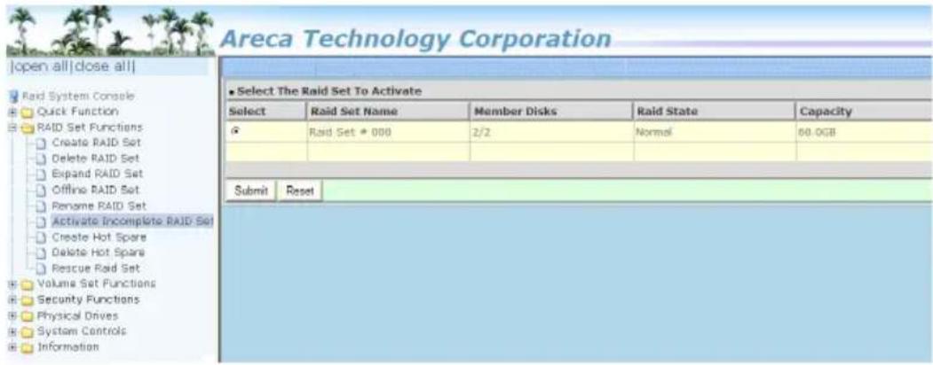
6.5.7 Create Hot Spare
When you choose the "Create Hot Spare" option in the "Raid Set Function", all unused physical devices connected to the current controller appear. Select the target disk by clicking on the appropriate check box. Click the "Confirm The Operation" check box and click the "Submit" button in the screen to create the hot spares. The "Create Hot Spare" gives you the ability to define a global or dedicated hot spare. Unlike "Global Hot Spare" which can be used with any RAID sets, "Dedicated Hot Spare" can only be used with a specific RAID set or Enclosure. Under "Global For SSD or HDD" option, SSD hot spare is used to rebuild failed SSD and HDD hot spare for rebuild failed HDD. When a disk drive fails in the RAID set or enclosure with a dedicated hot spare is pre-set, data on the disk drive is rebuild automatically on the dedicated hot spare disk.
![Areca Technology Corporation [open all|close all] Raid System Console Quick Function RAID Set Functions Create RAID Set Delete RAID Set Expand RAID Set Offline RAID Set Rename RAID Set Activate Incomplete RAID Set Create Hot Spare Delete Hot Spare Rescue Raid Set Volume Set Functions Security Functi…](/content/2026/05/990737/images/81c20e28aeaf740360dfbead896e87833712d8a47685221b1f8a1b2500242760.jpg)
6.5.8 Delete Hot Spare
Select the target hot spare disk to delete by clicking on the appropriate check box. Click the "Confirm The Operation" check box and click the "Submit" button on the screen to delete the hot spares.
![Areca Technology Corporation [open all|close all] Raid System Console Quick Function RAID Set Functions Create RAID Set Delete RAID Set Expand RAID Set Offline RAID Set Rename RAID Set Activate Incomplete RAID Set Create Hot Spare Delete Hot Spare Rescue Raid Set Volume Set Functions Security Functi…](/content/2026/05/990737/images/149d25d1b1f8e23428f0ad6e1260f9377dbfecbfd2505c5992684c3aa46809a3.jpg)
6.5.9 Rescue Raid Set
When the system is powered off in the RAID set update/creation period, the configuration possibly could disappear due to this abnormal condition. The "RESCUE" function can recover the missing RAID set information. The RAID controller uses the time as the RAID set signature. The RAID set may have different time after the RAID set is recovered. The "SIGANT" function can regenerate the signature for the RAID set.
![Areca Technology Corporation [open all|close all] Rad System Console Quick Function RAID Set Functions Create RAID Set Delete RAID Set Expand RAID Set Offline RAID Set Rename RAID Set Activate Incomplete RAID Set Create Hot Spare Delete Hot Spare Rescue Raid Set Volume Set Functions Security Functio…](/content/2026/05/990737/images/5c01f5c41cef5aa472bdfdac6436e0251f3be2a57afb13fef830f65f1cbec16b.jpg)
Caution:
Please contact us to make sure if you need to use rescue function. Improperly usage may cause configuration corruption.
6.6 Volume Set Functions
A volume set is seen by the host system as a single logical device. It is organized in a RAID level with one or more physical disks. RAID level refers to the level of data performance and protection of a volume set. A volume set capacity can consume all or a portion of the disk capacity available in a RAID set. Multiple volume sets can exist on a group of disks in a RAID set. Additional volume sets created in a specified RAID set will reside on all the physical disks in the RAID set. Thus each volume set on the RAID set will have its data spread evenly across all the disks in the RAID set.
The following summaries are the volume set features for the 6Gb/s SATA RAID controller.
- Volume sets of different RAID levels may coexist on the same RAID set and up to 128 volume sets per controller.
- Up to 128 volume sets can be created in a RAID set.
- The maximum addressable size of a single volume set is not limited to 2TB, because the controller is capable of 64-bit LBA mode. However the operating system itself may not be capable of addressing more than 2TB.
6.6.1 Create Volume Set (0/1)
To create volume set from RAID set system, move the cursor bar to the main menu and click on the "Create Volume Set" link. The "Select The Raid Set To Create On It" screen will show all RAID set number. Tick on a RAID set number that you want to create and then click on the "Submit" button.
The new create volume set attribute allows user to select the Volume Name, RAID Level, Capacity, Greater Two TB Volume Support, Initialization Mode, Strip Size, Cache Mode, Tagged Command Queuing, and SCSI Channel/SCSI ID/SCSI LUN.
![Areca Technology Corporation [open all|close all] Field System Outcode Quick Function RAID Set Function Volume Set Functions Create Volume Set Delete NAV30/30/00 Modify Volume Set Check Volume Set Schedule Volume Check Stop Volume Check Security Function Physical Drives System Controls Information E…](/content/2026/05/990737/images/0e4b023c91441c8821ab2ea2337cb28080c6a565854be80a54f8b996da93a828.jpg)
- Volume Name
The default volume name will always appear as "ARC-1203-VOL". You can rename the volume set providing it does not exceed the 15 characters limit.
• Volume Raid Level
Set the Raid Level for the volume set. Highlight the desired RAID level from the available RAID levels option.
- Capacity
The maximum volume size is the default initial setting. Enter the appropriate volume size to fit your application.
- Greater Two TB Volume Support
If volume capacity will exceed 2TB, controller will show the "Greater Two TB Volume Support" sub-menu. Greater Two TB Volume Support option: "No", "64bit LBA" and "4K Block".
- No
When this option is enabled, it keeps the volume size with max. 2TB limitation. For any hard disk drives working in the 4K native mode in the Raid set, the volume set directly sets and exposes 4KB sector size to the operating system.
- 64bit LBA
This option uses 16 bytes CDB instead of 10 bytes. The maximum volume capacity up to 512TB. For any hard disk drives working in the 4K native mode in the Raid set, the volume set directly sets and exposes 4KB sector size to the operating system.
This option works on different OS which supports 16 bytes CDB.
- 4K Block
This option uses 16 bytes CDB and changes the sector size from default 512 bytes to 4k bytes. Windows XP only supports maximum volume capacity is up to 16TB.
- Initialization Mode
This option is used to define "Background Initialization", "Foreground Initialization" or "No Init (To Rescue Volume)". When "Background Initialization", the initialization proceeds as a background task, the volume set is fully accessible for system reads and writes. The operating system can instantly access to the newly created arrays without requiring a reboot and waiting the initialization complete. When "Foreground Initialization", the initialization proceeds must be completed before the volume set ready for system accesses. There is no initialization happened when you select "No Init" option. "No Init" is for customer to rescue volume without losing data in the disk.
Note:
Controller starts to initialize the volume in two conditions
- Stay in controller bios manager or
- Boot into OS and the controller driver loaded.
- Stripe Size
This parameter sets the size of the stripe written to each disk in a RAID 0 or 1 logical drive. You can set the stripe size to 4KB, 8KB, 16KB, 32KB, 64KB, 128KB, 256KB, 512KB, or 1024KB. A larger stripe size produces better read performance, especially if your computer does mostly sequential reads. However, if you are sure that your computer does random reads more often, select a smaller stripe size.
- Cache Mode
The 6Gb/s SATA RAID controller supports "Write Through" and "Write Back" cache.
• Volume Write Protection
When "Volume Write Protection" is enabled on the "Modify Volume Set", host commands fail if they are issued to a volume in that RAID controller and attempt to modify a volume's data or attributes. Volume Write Protection is used primarily for customer-initiated disaster recovery testing.
- Tagged Command Queuing
The “Enabled” option is useful for enhancing overall system performance under multi-tasking operating systems. The Command Tag (Drive Channel) function controls the SATA command tag queuing support for each drive channel. This function should normally remain “Enabled”. “Disabled” this function only when using SATA drives that do not support command tag queuing.
• SCSI Channel/SCSI ID/SCSI Lun
SCSI Channel: The 6Gb/s SATA RAID controller function is simulated as an external SCSI RAID controller. The host bus is represented as a SCSI channel. Choose the SCSI Channel.
SCSI ID: Each SCSI device attached to the SCSI card, as well as the card itself, must be assigned an unique SCSI ID number. A SCSI channel can connect up to 15 devices. The 6Gb/s SATA RAID controller is a large SCSI device. Assign an ID from a list of SCSI IDs.
SCSI LUN: Each SCSI ID can support up to 8 LUNs. Most 6Gb/s SATA controllers treat each LUN like a SATA disk.
6.6.2 Delete Volume Set
To delete a volume from RAID set, move the cursor bar to the main menu and click on the "Delete Volume Set" link. The "Select The Raid Set To Delete" screen will show all RAID set numbers. Click a RAID set number and the "Confirm The Operation" check box and then click the "Submit" button to show all volume set items in the selected RAID set. Click a volume set number and the "Confirm The Operation" check box and then click the "Submit" button to delete the volume set.
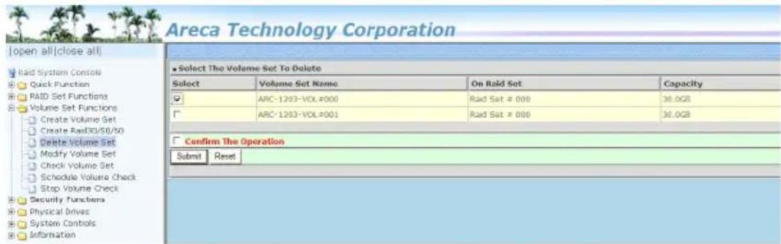
6.6.3 Modify Volume Set
To modify a volume set from a RAID set:
- Click on the "Modify Volume Set" link.
- Click the volume set check box from the list that you wish to modify. Click the "Submit" button. The following screen appears.

Use this option to modify the volume set configuration. To modify volume set attributes, move the cursor bar to the volume set attribute menu and click it. The "Enter The Volume Attribute" screen appears. Move the cursor to an attribute item and then click the attribute to modify the value. After you complete the modification, click the "Confirm The Operation" check box and click the "Submit" button to complete the action. The user can only modify the last volume set capacity.
6.6.3.1 Volume Growth
Use "Expand RAID Set" function to add disk to a RAID set. The additional capacity can be used to enlarge the last volume set size or to create another volume set. The "Modify Volume Set" function can support the "Volume Modification" function. To expand the last volume set capacity, move the cursor bar to
the "Capacity" item and entry the capacity size. When finished the above action, click on the "Sumbit" button to complete the action. The last volume set starts to expand its capacity.
To expand an existing volume noticed:
- Only the last volume can expand capacity.
- When expand volume capacity, you can't modify stripe size or modify RAID level simultaneously.
- You can expand volume capacity, but can't reduce volume capacity size.
- After volume expansion, the volume capacity can't be decreased.
For greater 2TB expansion:
- If your system installed in the volume, don't expand the volume capacity greater 2TB; except your OS and RAID controller can support boot up from a greater 2TB capacity device.
- Expand over 2TB used LBA64 mode. Please make sure your OS supports LBA64 before expand it.
6.6.3.2 Volume Set Migration
Migrating occurs when a volume set is migrating from one RAID level to another, when a volume set strip size changes, or when a disk is added to a RAID set. Migration state is displayed in the volume state area of the "Volume Set Information" screen.

Note:
Power failure may damage the migration data. Please backup the RAID data before you start the migration function.
6.6.4 Check Volume Set
To check a volume set from a RAID set:
- Click on the "Check Volume Set" link.
- Click on the volume set from the list that you wish to check.
Click on "Confirm The Operation" and click on the "Submit" button. Use this option to verify the correctness of the redundant data in a volume set. For example, in a system with dedicated parity, volume set check means computing the parity of the data disk drives and comparing the results to the contents of the dedicated parity disk drive. The checking percentage can also be viewed by clicking on "RAID Set Hierarchy" in the main menu.
6.6.5 Stop Volume Set Check
Use this option to stop the "Check Volume Set" function.
![Areca Technology Corporation [open all]close all] Rad System Console Quick Function RAID Set Functions Volume Set Functions Create Volume Set Create Paid30/50/60 Delete Volume Set Modify Volume Set Check Volume Set Schedule Volume Check Stop Volume Check Security Functions Physical Drives System Con…](/content/2026/05/990737/images/7722a8863148d369ef045e6f1d83406d4f97b7e143abc0a8cc601b380a9fb9a9.jpg)
6.7 Physical Drive
Choose this option to select a physical disk from the main menu and then perform the operations listed below.
6.7.1 Create Pass-Through Disk
To create pass-through disk, move the mouse cursor to the main menu and click on the "Create Pass-Through" link. The relative setting function screen appears. A pass-through disk is not controlled by the 6Gb/s SATA RAID controller firmware; it can't be a part of a volume set. The disk is available to the operating system as an individual disk. It is typically used on a system where the operating system is on a disk not controlled by the RAID firmware. The user can also select the Volume Cache Mode, Write Protection, Tagged Command Queuing, and SCSI channel/SCSI_ID/SCSI_LUN for this pass-through disk.

6.7.2 Modify Pass-Through Disk
Use this option to modify the pass-through disk attribute. The user can modify the Cache Mode, Tagged Command Queuing, and SCSI Channel/ID/LUN on an existing pass-through disk.
To modify the pass-through drive attribute from the pass-through drive pool, move the mouse cursor bar and click on the "Modify Pass-Through" link. The "Select The Pass Through Disk For Modi-
fication" screen appears mark the check box for the pass-through disk from the pass-through drive pool and click on the "Submit" button to select drive. When the "Enter Pass-Through Disk Attribute" screen appears, modify the drive attribute values, as you want. After you complete the selection, mark the check box for "Confirm The Operation" and click on the "Submit" button to complete the selection action.

6.7.3 Delete Pass-Through Disk
To delete a pass-through drive from the pass-through drive pool, move the mouse cursor bar to the main menus and click the "Delete Pass Through" link. After you complete the selection, mark the check box for "Confirm The Operation" and click the "Submit" button to complete the delete action.
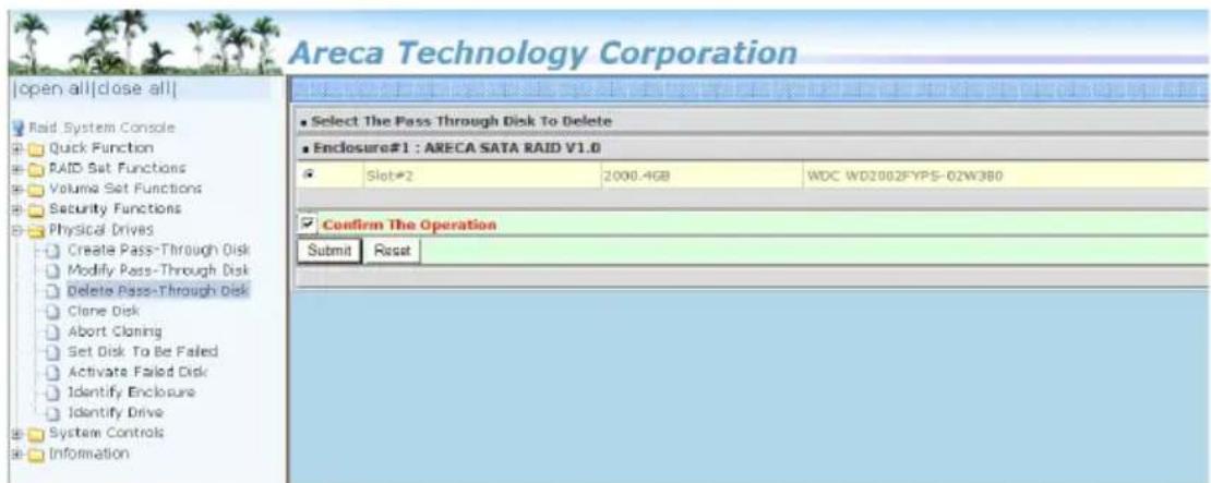
6.7.4 Clone Disk
Instead of deleting a RAID set and recreating it with larger disk drives, the "Clone Disk" function allows the users to replace larger disk drives to the RAID set that have already been created. Click the "Clone Disk" option on the "Physical Drives" link to enable the clone function. If there is an available disk, then the "Select The Drives For Cloning" screen appears. There are two "Clone Disk" function options: "Clone And Replace" and "Clone Only."
![Areca Technology Corporation [open all]close oil] Card System Console Quick Function RAID Sat Functions Volume Set Functions Security Functions Physical Drives Create Pass-Through Disk Modify Pass-Through Disk Delete Pass-Through Disk Clone Type: ABOUT Cloning Set Disk To Be Failed Activate Failed D…](/content/2026/05/990737/images/cf2c2c13f6693032560a3a6c46923ec9ccb342d09a84b0cb5171e9dee3adc4a1.jpg)
Clone Disk Procedure
- Select one of the members as the "Clone Source" (status indicated as Raid Set #) by clicking on the appropriate check box.
- Select a "Clone Target" (status indicated as Free or Hot Spare) by clicking on the appropriate check box.
- If you have available disk member, you can repeat above procedures to define another clone pair.
- Select Clone Type.
The pair number for both the “Clone Source” and the “Clone Target” will be indicated in the screen. Click the “Confirm The Operation” check box and click on the “Submit” button on the screen; the controller will automatically start the cloning process using the existing “stand-by” (Free or Hot Spare drive) to clone the source drive (the Raid Set member drive). The cloning process percentage will be indicated in the “Volume State” area of the “Volume Set Information” screen. Completion of the Clone function process will be indicated by a notification message on the event log.
6.7.4.1 Clone And Replace
You can enlarge your logical drives by copying and replacing all member drives with drives of higher capacity. The existing data in the logical drives is copied onto the new drives, and then the original members are marked as "Offlined".
6.7.4.2 Clone Only
The stand-by disk will clone the logical drives without substituting it. The status of the stand-by drive will be marked as "Off-lined" after the cloning process. The source drive will remain a member of the logical drive.
6.7.5 Abort Cloning
Use this function to stop the ongoing clone disk action.
6.7.6 Set Disk To Be Failed
It sets a normal working disk as "failed" so that users can test some of the features and functions.
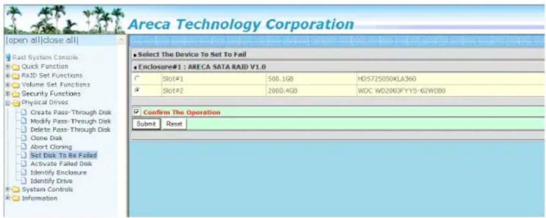
6.7.7 Activate Failed Disk
It forces the current "failed" disk in the system to be back online. "Activate Failed Disk" function has no effect on the removed disks, because a "removed" disk does not give the controller a chance to mark it as "failure".
Followings are considered as "Removed-Disk":
- Manually removed by user
- Losing PHY connection due to bad connector, cable, backplane
- Losing PHY connection due to disk fail
Basically, in the eyes of the controller, the disk suddenly disappears due to whatever reason.
![Areca Technology Corporation [open all|close all] Raid System Console Quick Function RAID Set Functions Volume Set Functions Security Functions Physical Drives Create Pass-Through Disk Modify Pass-Through Disk Delete Pass-Through Disk Clone Disk Abort Cloning Set Disk To Be Failed Activate Failed Di…](/content/2026/05/990737/images/203c74773375455796a463de586fd0ce83467aaa501999a2d536dbd78115113d.jpg)
6.7.8 Identify Enclosure
To prevent removing the wrong enclosure, the selected Areca expander enclosure all disks fault LED indicator will light for physically locating the selected enclosure when the "Identify Enclosure" is selected. This function will also light the enclosure LED indicator, if it is existed.
![Areca Technology Corporation [open all|close all] Rack System Console Quick Function RAID Set Functions Volume Set Functions Security Functions Physical Drives Create Pass- Through Disk Modify Pass- Through Disk Delete Pass- Through Disk Clone Disk Abort Cloning Set Disk To Be Failed Activate Failed…](/content/2026/05/990737/images/e01c67ae80c6b24b4a3bf2fc02fd5bacac41f8a3c669787a213113bab2b43ca0.jpg)
6.7.9 Identify Drive
To prevent removing the wrong drive, the selected disk fault LED indicator will light for physically locating the selected disk when the "Identify Selected Device" is selected.

6.8 System Controls
6.8.1 System Config
To set the RAID system function, move the cursor to the main menu and click the "System Controls" link. The "Raid System Function" menu will show all items, and then select the desired function.

• System Beeper Setting
The "System Beeper Setting" function is used to "Disabled" or "Enabled" the 6Gb/s SATA RAID controller alarm tone generator.
• Background Task Priority
The "Background Task Priority" is a relative indication of how much time the controller devotes to a rebuild operation. The 6Gb/s SATA RAID controller allows the user to choose the rebuild priority (UltraLow, Low, Medium and High) to balance volume set access and rebuild tasks appropriately. For high array performance, specify a "Low" value.
• JBOD/RAID Configuration
JBOD is an acronym for "Just a Bunch Of Disk". A group of hard disks in a RAID box are not set up as any type of RAID configuration. All drives are available to the operating system as an individual disk. JBOD does not provide data redundancy.
User needs to delete the RAID set, when you want to change the option from the RAID to the JBOD function.
- SATA NCQ Support
The controller supports both SATA and SATA disk drives. The SATA NCQ allows multiple commands to be outstanding within a drive at the same time. Drives that support NCQ have an internal queue where outstanding commands can be dynamically rescheduled or re-ordered, along with the necessary tracking mechanisms for outstanding and completed portions of the workload. The 6Gb/s SATA RAID controller allows the user to select the SATA NCQ support: "Enabled" or "Disabled".
- HDD Read Ahead Cache
Allow Read Ahead (Default: Enabled)—When Enabled, the drive's read ahead cache algorithm is used, providing maximum performance under most circumstances.
• Volume Data Read Ahead
The volume read data ahead parameter specifies the controller firmware algorithms which process the Read Ahead data blocks from the disk. The read ahead parameter is normal by default. To modify the value, you must set it from the command line using the Read Ahead option. The normal option satisfies the performance requirements for a typical volume. The disabled value implies no read ahead. The most efficient value for the controllers depends on your application. Aggressive read ahead is optimal for sequential access but it degrades random access.
• Empty HDD Slot LED
The firmware has added the "Empty HDD Slot LED" option to setup the fault LED light "ON "or "OFF" when there is no HDD installed. When each slot has a power LED for the HDD installed identify, user can set this option to "OFF". Choose option "ON", the 6Gb/s SATA RAID controller will light the fault LED; if no HDD installed.
• Max Command Length
Max Command Length is used to set a "best" IO size for the RAID controller.
• Auto Activate Incomplete Raid
When some of the disk drives are removed in power off state or boot up stage, the RAID set state will change to "Incomplete State". But if a user wants to automatically continue to work while the 6Gb/s SATA RAID controller is powered on, the user can set the "Auto Activate Incomplete Raid" option to enable. The RAID state will change to "Degraded Mode" while it powers on.
- Disk Write Cache Mode
User can set the "Disk Write Cache Mode" to Auto, Enabled, or Disabled. "Enabled" increases speed, "Disabled" increases reliability.
- Write Same For Initialization
Drives that support the Write Same feature (SCT) can write to multiple drive sectors at once, improving initialization time. To take advantage of this feature, all the drives in the unit must support Write Same. User can set the “Enabled” or “Disabled” for the controller initialization.
• Hot Plugged Disk For Rebuilding
It defines if the RAID array volume should start rebuilding or not when detects a disk is inserted/re-inserted during online. The options are: "Blank Disk Only", "Always", and "Disable". The default is "Blank Disk Only".
"Blank Disk Only" - it will trigger the rebuilding if and only if the inserted disk has not been in the RAID array before, which has no RAID signature on it. So when a previously removed disk is self re-inserted, it won't trigger the degraded RAID array to rebuild, and so that the administrator has a chance to identify this miss-behaving disk and replace it.
"Always" – it is what it was before. Whenever a disk is inserted/re-inserted whether new or previously existed, it always triggers a rebuilding for the Degraded RAID set/Volume.
"Disable" – it will not trigger rebuilding regardless what sort of disk plugging in. When "Disable" and/or "Blank Disk Only" is selected, the re-inserted/previously removed disk will be iden-
tified as a disk in a separate RAID set with duplicated RAID-set# and with all the rest of RAID members missing.
- Disk Capacity Truncation Mode
Areca RAID controller uses drive truncation so that drives from differing vendors are more likely to be able to be used as spares for each other. Drive truncation slightly decreases the usable capacity of a drive that is used in redundant units. The controller provides three truncation modes in the system configuration: "Multiples Of 10G", "Multiples Of 1G", and "Disabled".
Multiples Of 10G: If you have 120 GB drives from different vendors; chances are that the capacity varies slightly. For example, one drive might be 123.5 GB, and the other 120 GB. Multiples Of 10G truncates the number under tens. This makes same capacity for both of these drives so that one could replace the other.
Multiples Of 1G: If you have 123 GB drives from different vendors; chances are that the capacity varies slightly. For example, one drive might be 123.5 GB, and the other 123.4 GB. Multiples Of 1G truncates the fractional part. This makes capacity for both of these drives so that one could replace the other.
Disabled: It does not truncate the capacity.
- Smart Option For HDD
This option is used to increase the reliability of SSDs/HDDs by automatically copying data from a drive with potential to fail to a designated hot spare or newly inserted drive. The options are: "Failed The Drive", "Failed The Drive If Hot Sapre Exist", and "Alert Only". The default is "Alert Only"
"Failed The Drive" – controllers kill off the SMART fail drive immediately.
"Failed The Drive If Hot Sapre Exist" – controllers kill off the SMART fail disk if hot sapre dive is existed.
"Alert" – it will trigger alert when there happens a SMART fail drive.
• Smart Polling Interval
Besides the scheduled volume check, user can define the Smart Pulling Interval to pull the SMART status of each disk. The default is "on demand". User can schedule every certain period of time interval to pull the SMART status of each disk. When SMART pulling is executed, disk activity will be temporally halted until the SMART parameter reading is finished. That is why you don't want to set the "Smart Polling Interval" too frequent. What to use is up to the users to decide based on their applications and experimental results.
6.8.2 Advanced Configuration
To set the RAID system function, move the cursor to the main menu and click the "Advanced Configuration" link. The "Advanced Configuration" menu will show all items, and then select the desired function.
![Areca Technology Corporation [open all|close all] Rad System Console Quick Function RAID Set Functions Volume Set Functions Security Functions Physical Drives System Controls System Configuration Advanced Configuration Hold Power Management Ethernet Configuration Alert By Mail Configuration SNMP Con…](/content/2026/05/990737/images/6acbd211fc19e25fe97fb969ac11470e6a8a6f904d17461c7520498fb3450039.jpg)
- TLER Setting
TLER (time-limited error recovery) functions provide support for WD Caviar RE (RAID) series disks. This is a new option from WD to support RAID features that were traditionally missing from standard desktop drives. TLER is a method of signaling the system RAID controller in the event that an error recovery process is taking longer than time-out specifications allow. This prevents the RAID controller from dropping the drive from the array during this period. Default value is manufacture setting. You can select between 5, 6 and 7 second. This feature is used to setup the HDD internal timeout value.
- Timeout Setting
Disk time-out is a registry setting that defines the time that RAID controller will wait for a hard disk to respond to a command. You can modify the retry value by entering a new value in the edit box beside this button and then selecting the button. Normally you should not need to modify this value. Default value is 8 seconds: You can select between 3\~8 second.
• Number of Retries
This setting determines the number of access that will be attempted before the current command from the RAID controller to the disk drive is aborted. You can modify the retry value by entering a new value in the edit box beside this button and then selecting the button. Normally you should not need to modify this value. There are two selections, either 2 retry or 3 retry.
- Buffer Threshold
This new feature there are 3 options; 25%, 50%, 75%. The percentage represents how much data should be kept in resident cache memory (how full cache should get) before controller starts to flush data onto the hard drives. If the buffer is set for 25%, then all 25% will be cached and is used for writing data. The remaining cache memory will be used for reading and other system overhead. Write buffer threshold for 5% is added for video recording. This option will push data to disk early.
This feature gives controller extra buffer time in case of slow response from the hard drives within a given time. Consequently, this can prevent a pause in data flow and there will be continued data access and stream. This feature is very useful for the video streaming applications where there is high demand for constant non-stop data flow with no interruption due to lower performance of specific hardware.
- Amount of Read Ahead
Read-Ahead data is buffered in the RAID controller cache, however, thereby cutting down on the amount of I/O traffic to the disk. The Amount of Read Ahead defines how many data of reading at a time, making more efficient use of the RAID
subsystem. This makes it possible to locate and re-issue the data without repetitive hard parsing activities.
The Amount of Read Ahead parameter is used to allocate an amount of memory in the cache memory the frequently executed queries and return the result set back to the host without real disk read execution. Default value is Auto: Controller will base on the HDD number to set the Amount of Read Ahead value. You can select between 512KB \~ 16MB.
• Number of AV Stream
RAID controllers are required to have not only the function of processing ordinary data but also the function of dealing with AV (audio/video) stream data needing real-time processing. Since the bus cycle used in RAID controller was designed to transfer the computer data exactly, it was unsuitable for the transfer of AV stream needing great band widths. They are required to do some setting for the handshaking during the processing of stream data. This setting is an object of transferring stream data efficiently on an existing RAID controller. Normally you should not need to modify this value. Default value is 6. You can select between 6\~256.
To decide how to set AV stream play out parameter, you need to check the Number of Stream, Amount of Read Ahead, and Total Cache Memory during runtime. You can try to adjust the three numbers to get the best performance as your requirement. Number of AV Stream shows the number of stream added to the system, Amount of Read Ahead shows the Amount of Read Ahead data taken from the cache without real disk execution, and total cache memory shows the total available memory being installed in the RAID controller.
- Optimize AV Recording
AV recording option is for video recording (no time limit), but if used in normal operation, performance may be degraded. This new feature there are 4 options; Disabled, Mode1, Mode2 and Mode 3. Default value is Disabled. Our controller cache uses LRU method; there have no special memory capacity reserved for read or write. The Mode 1, 2 and 3 are used to define the command sorting method. The default sorting method
is helpful for normal applications, but not useful for AV applications, so we have defined three different sorting methods for these special applications. To decide how to optimize AV stream recording parameter, you need to adjust the Optimize AV Recording, and Write Buffer Threshold during runtime.
- Read Performance Margin
The "Read Performance Margin" is for controller to reserve n% read margin during AV stream recording. It is designed to eliminate the frame drop and ensure to provide the smooth and stable performance on the application.
- Write Performance Margin
The "Write Performance Margin" is for controller to reserve n% write margin AV stream recording. It is designed to eliminate the frame drop and ensure to provide the smooth and stable performance on the application.
- Read And Discard Parity Data
This function is used to determine if parity data is to be read and discarded. It is designed to eliminate the frame drop and ensure to provide the smooth and stable performance on the application.
- BIOS Selection
It combines the "Legacy BIOS" and "UEFI BIOS" and "EFI BIOS" into a single BIOS, and provide BIOS option in the GUI. In the old days, Areca provided separate BIOS files for each, and need to manually flesh it in. Now fleshing BIOS for different BIOS type is no longer needed, just make the BIOS selection in System Controls: Advance Configuration: BIOS Option
BIOS Option
Legacy: for motherboards that are using regular BIOS boot.
UEFI: for motherboards (especially Intel's motherboards) using UEFI boot
EFI: for Intel based MacPro boot
Disable: disable controller BIOS at POST (set to 0xFF)
==> If BIOS is to be disabled --> All data are 0xFF
6.8.3 HDD Power Management
The 6Gb/s SATA RAID controller has automated the ability to manage HDD power based on usage patterns. The "HDD Power Management" allows you to choose a "Stagger Power On Control", "Low Power Idle", "Low RPM" and completely "Spins Down Idle HDD". It is designed to reduce power consumption and heat generation on idle drives.
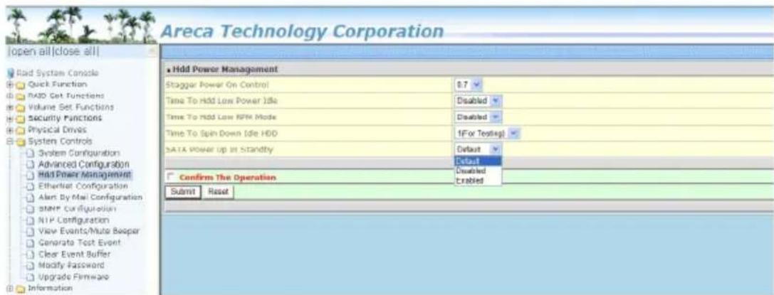
- Stagger Power On Control
In a PC system with only one or two drives, the power can supply enough power to spin up both drives simultaneously. But in systems with more than two drives, the startup current from spinning up the drives all at once can overload the power supply, causing damage to the power supply, disk drives and other system components. This damage can be avoided by allowing the host to stagger the spin-up of the drives. The SATA drives have supported the staggered spin-up capabilities to boost reliability. The staggered drive spin-up is a very useful feature for managing multiple disk drives in a storage sub-system. It gives the host the ability to spin up the disk drives sequentially or in groups, allowing the drives to come ready at the optimum time without straining the system power supply. The staggered drive spin-up in a multiple drive environment also avoids the extra cost of a power supply designed to meet short-term startup power demand as well as steady state conditions.
The 6Gb/s SATA RAID controller has included the option for customer to select the disk drives sequentially staggered power up value. The values can be selected from 0.4 to 6 seconds per step which powers up one drive.
• Time To Hdd Low Power Idle
This option delivers lower power consumption by automatically unloading recording heads during the setting idle time. The values can be selected "Disabled" or within the range 2 to 7 minutes.
• Time To Hdd Low RPM Mode
This function can automatically spin disks at lower RPM if there have not been used during the setting idle time. The values can be selected "Disabled" or within the range 10 to 60 minutes.
• Time To Spin Down Idle HDD
This function can automatically spin down the drive if it hasn't been accessed for a certain amount of time. This value is used by the drive to determine how long to wait (with no disk activity, before turning off the spindle motor to save power). The values can be selected "Disabled" or within the range 1 to 60 minutes.
• SATA Power Up In Standby
SATA Power Up In Standby (power management 2 mode, PM2) is a SATA disk drive configuration which prevents the drive from automatic spinup when power is applied. "Enabled" option allows the drive to be powered-up into the Standby power management state to minimize inrush current at power-up and to allow the controller to sequence the spinup of devices. It is mainly for server/workstation environments operating in multiple-drive configurations.
6.8.4 View Events/Mute Beeper
To view the 6Gb/s SATA RAID controller's event information, click on the "View Event/Mute Beeper" link. The 6Gb/s SATA RAID controller "System events Information" screen appears. The mute beeper function automatically enable by clicking on "View Events/Mute Beeper".
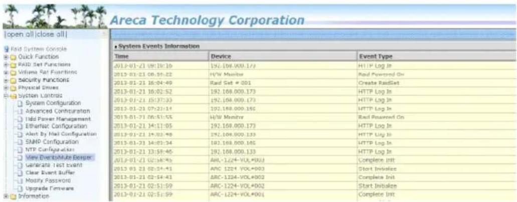
Select this option to view the system events information: Time, Device, Event Type, Elapse Time and Errors. The RAID controller does not have a built-in real time clock. The time information is the relative time from the system time setting. The maximum event no. is 256 per controller.
6.8.5 Generate Test Event
Use this feature is generate events for testing purposes.
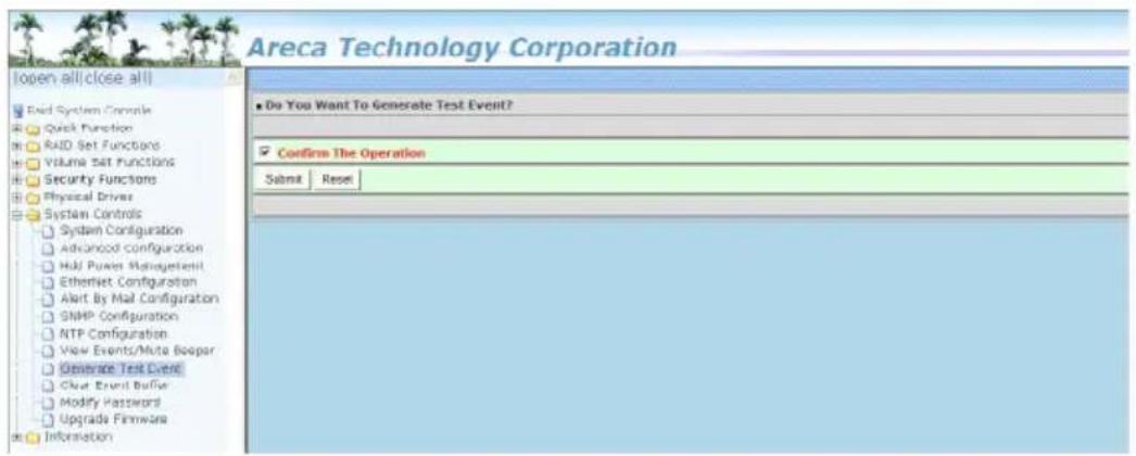
6.8.6 Clear Events Buffer
Use this feature to clear the entire events buffer information.

6.8.7 Modify Password
To set or change the 6Gb/s SATA RAID controller password, select "System Controls" from the menu and click on the "Modify Password" link. The "Modify System Password" screen appears.
The manufacture default password is set to 0000.
The password option allows user to set or clear the 6Gb/s SATA RAID controller's password protection feature. Once the password has been set, the user can only monitor and configure the 6Gb/s SATA RAID controller by providing the correct password. The password is used to protect the 6Gb/s SATA RAID controller from unauthorized entry. The controller will check the password only when entering the main menu from the initial screen. The 6Gb/s SATA RAID controller will automatically go back to the initial screen when it does not receive any command in 5 minutes. Do not use spaces when you enter the password, If spaces are used, it will lock out the user.
To disable the password, leave the fields blank. Once the user confirms the operation and clicks the "Submit" button, the existing password will be cleared. Then, no password checking will occur when entering the main menu from the starting screen.
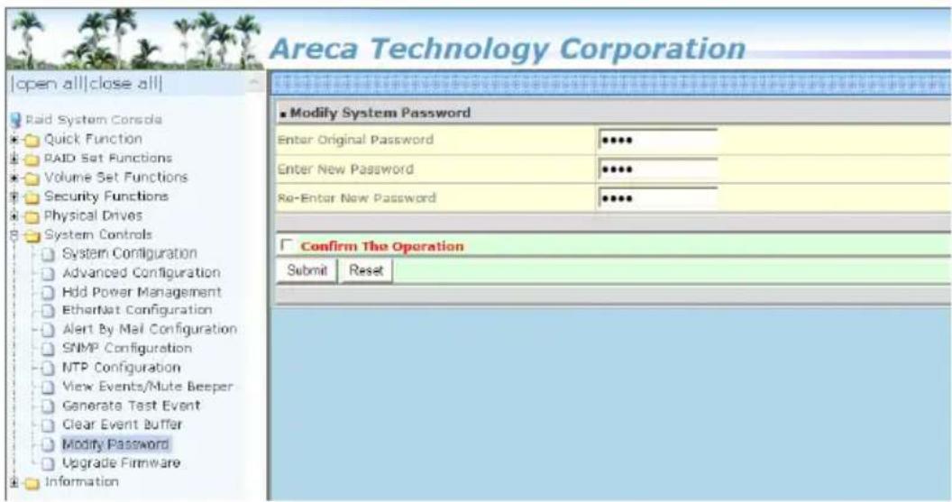
6.8.8 Update Firmware
Please refer to the appendix A "Upgrading Flash ROM Update Process".
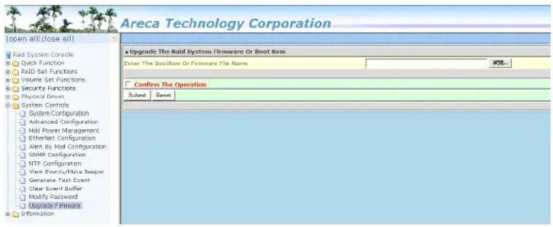
6.9 Information
6.9.1 Raid Set Hierarchy
Use this feature to view the 6Gb/s SATA RAID controller current RAID set, current volume set and physical disk information. The volume state and capacity are also shown on this screen.
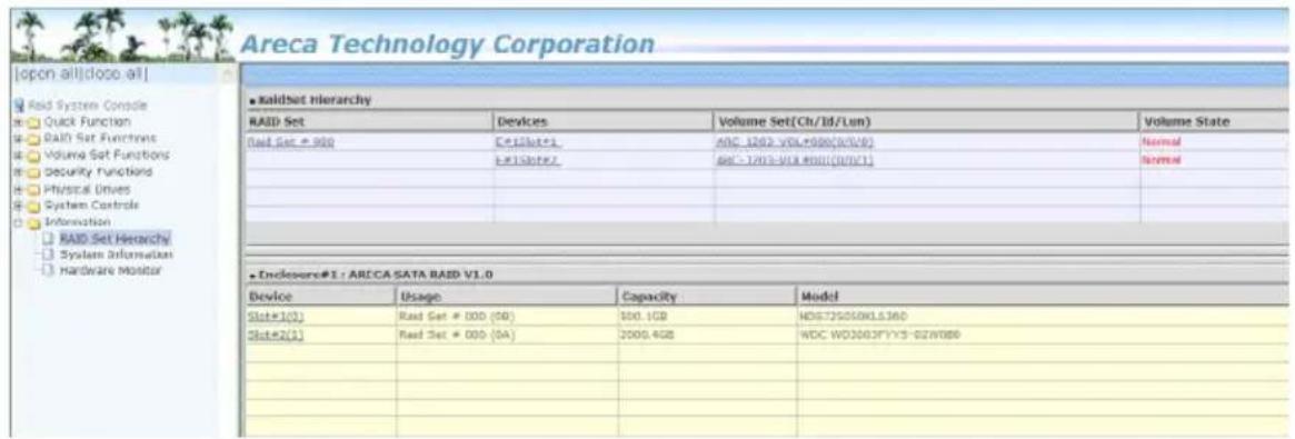
6.9.2 System Information
To view the 6Gb/s SATA RAID controller's system information, move the mouse cursor to the main menu and click on the "System Information" link. The 6Gb/s SATA RAID controller "RAID Subsystem Information" screen appears.
Use this feature to view the 6Gb/s SATA RAID controller's system information. The controller name, controller firmware version, Boot ROM version, SATA firmware version, serial number, main processor, CPU instruction/data cache size, system memory size/speed and current IP address appear in this screen.
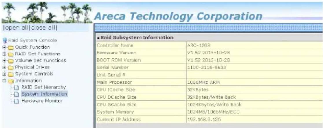
6.9.3 Hardware Monitor
The hardware monitor information of this controller is shown on this screen.

Appendix A
Upgrading Flash ROM Update Process
A-1 Overview
Since the ARC-1203-2I RAID controllers feature flash ROM firmware, it is not necessary to change the hardware flash chip in order to upgrade the RAID firmware. The user can simply re-program the old firmware through the in-band PCIe bus McRAID Storage manager and nflash DOS utility. New releases of the firmware are available in the form of a DOS file on the shipped CD or Areca website. The files available at the FTP site for each model contain the following files in each version:
ARC1203NNNN.BIN Software Binary Code ("NNNN" refers to the software code type)
ARC1203BIOS.BIN:→ PCIe 2.0 BIOS for system board using ARC1203BOOT.BIN:→ RAID controller hardware initialization ARC1203FIRM.BIN:→ RAID kernel program
ARC1203MBR0.BIN:→ Master Boot Record for supporting Dual Flash Image in the 6Gb/s SATA RAID controller
README.TXT contains the history information of the software code change in the main directory. Read this file first to make sure you are upgrading to the proper binary file. Select the right file for the upgrade. Normally, user upgrades the ARC1203BIOS. BIN for system M/B compatibility and ARC1203FIRM.BIN for RAID function. All these files in the firmware package are a part of the firmware. You should update all files in the package, no special update order needed. New firmware works after a system restart not instant available, so you can update all files before restart the system. The controller firmware is independent of the array, and update firmware does not touch anything you stored in the array.
Note:
Please update all binary code (BIOS, BOOT FIRM and MBR0) before you reboot system. Otherwise, a mixed firmware package may hang the controller.
A-2 Upgrading Firmware Through McRAID Storage Manager
Get the new version firmware for your 6Gb/s SATA RAID controller. For example, download the bin file from your OEM's web site onto the C: drive.

- To upgrade the 6Gb/s SATA RAID controller firmware, move the mouse cursor to "Upgrade Firmware" link. The "Upgrade The Raid System Firmware or Boot Rom" screen appears.
- Click "Browse". Look in the location to which the Firmware upgrade software was downloaded. Select the file name and click "Open".
- Click "Confirm The Operation" and press the "Submit" button.
- The web browser begins to download the firmware binary to the controller and start to update the flash ROM.
- After the firmware upgrade is complete, a bar indicator will show "Firmware Has Been Updated Successfully".
- After the new firmware package completes downloading, find a chance to restart the controller/computer for the new firmware to take effect.
The web browser-based McRAID storage manager can be accessed through the in-band PCIe bus. The in-band method uses the ArcHTTP proxy server to launch the McRAID storage manager.
From a remote pc, you can directly open a web browser and enter the IP address. Then enter user name and password to login and start your management. You can find the firmware update feature from the "Raid System Console" on the "System Controls" option.
A-3 Upgrading Firmware Through nflash DOS Utility
Areca now offers an alternative means communication for the 6Gb/s SATA RAID controller – Upgrade the all files (BIOS, BOOT, FIRM and MBR0) without necessary system starting up to running the ArcHTTP proxy server. The nflash utility program is a DOS application, which runs in the DOS operating system. Be sure of ensuring properly to communicate between 6Gb/s SATA RAID controller and nflash DOS utility. Please make a bootable DOS floppy diskette or USB devices from other Windows operating system and boot up the system from those bootable devices.
- Starting the nflash Utility
You do not need to short any jumper cap on running nflash utility. The nflash utility provides an on-line table of contents, brief descriptions of the help sub-commands. The nflash utility put on the
A:\nflash
Raid Controller Flash Utility
V1.52 2013-11-07
Command Usage:
NFLASH FileName
NFLASH FileName /cn --> n=0,1,2,3 write binary to controller#0
FileName May Be ARC1203FIRM.BIN or ARC1203*
For ARC1203* Will Expand To ARC1203BOOT /FIRM/BIOS.BIN
A:\>nflash arc120~1.bin
Raid Controller Flash Utility
V1.52 2013-11-07
MODEL : ARC-1203
MEM FE620000 FE7FF000
File ARC120~1.BIN : >>>*** => Flash 0K
A-4 Upgrading Firmware Through CLI
This Command Line Interface (CLI) provides you to configure and manage the 6Gb/s SATA RAID controller components in Windows, Linux, FreeBSD and more environments. The CLI is useful in environments where a graphical user interface (GUI) is not available. Through the CLI, you perform firmware upgrade that you can perform with the McRAID storage manager GUI. The controller has added protocol on the firmware for user to update the controller firmware package (BIOS, BOOT, FIRM and MBRO) through the utility.
To update the controller firmware, follow the procedure below:
Parameter: <path=<PATH_OF_FIRMWARE_FILE>>
Fn: Firmware Updating.
Ex: Update Firmware And File Path Is In [C:\FW\ARC1203FIRM.BIN.]
Command: sys updatefw path=c:\fw\ARC1203firm.bin [Enter]
Appendix B
Battery Backup Module (ARC-6120BA-T121-12G)
B-1 Overview
The ARC-1203-2I 6Gb/s SATA RAID controller operates using cache memory. The Battery Backup Module is an add-on module that provides power to the ARC-1203-2I 6Gb/s SATA RAID controller cache memory in the event of a power failure. The Battery Backup Module monitors the write back cache on the ARC-1203-2I 6Gb/s SATA RAID controller, and provides power to the cache memory if it contains data not yet written to the hard drives when power failure occurs.
B-2 BBM Components
This section provides the board layout and connector/jumper for the BBM.
![graph TD A["JP2"] --> B["Battery Connector"] C["JP4"] --> B D[" "] --> E["Status of Battery"] F[" "] --> E G[" "] --> H["RAID Controller BBM's Connector"] I["J1"] --> H J["J2"] --> H style A fill:#f9f,stroke:#333 style C fill:#f9f,stroke:#333 style D fill:#ccf,stroke:#333 style E fill:#cfc,stroke:#3…](/content/2026/05/990737/images/96afb30a53a4fa76c4e32e8af884ef25b932506de21e3972dc1316315148d09b.jpg)
B-3 Status of BBM
• D7 (Green) : light when BBM activated
• D8 (Green) : light when BBM normal
• D9 (Red) : light when BBM charging
Note:
The BBM status will be shown on the web browser of "Hardware Monitor Information" screen.
B-4 Installation
- Make sure all power to the system is disconnected.
- The ARC-1203-2I 6Gb/s SATA RAID controller's battery connector is available for the optional battery backup module. Connect the BBM cable to the 14-pin battery connector on the controller.
- Integrators may provide pre-drilled holes in their cabinet for securing the BBM using its three mounting positions.
- Low profile bracket also provided.
- The BBM will occupy one PCI slot on the host backplane.
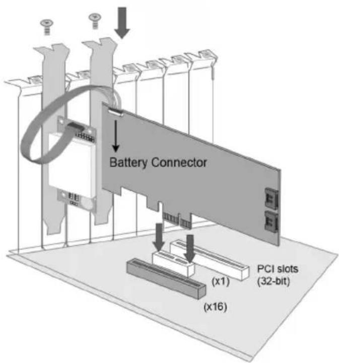
B-5 Battery Backup Capacity
Battery backup capacity is defined as the maximum duration of a power failure for which data in the cache memory can be maintained by the battery. The BBM's backup capacity varied with the memory chips that installed on the ARC-1203-2I 6Gb/s SATA RAID controller.
B-6 Operation
- Battery conditioning is automatic. There are no manual procedures for battery conditioning or preconditioning to be performed by the user.
- In order to make sure of all the capacity is available for your battery cells, allow the battery cell to be fully charged when installed for the first time. The first time charge of a battery cell takes about 24 hours to complete.
B-7 Changing the Battery Backup Module
At some point, the LI-ION battery will no longer accept a charge properly. LI-ION battery life expectancy is anywhere from approximately 1 to 5 years.
- Shutdown the operating system properly. Make sure that cache memory has been flushed.
- Disconnect the BBM cable from ARC-1203-2I 6Gb/s SATA RAID controller's battery connector.
- Disconnect the battery pack cable from JP2 on the BBM.
- Install a new battery pack and connect the new battery pack to JP2.
- Connect the BBM to ARC-1203-2I 6Gb/s SATA RAID controller's battery connector.
Note:
Do not remove BBM while system is running.
B-8 Battery Functionality Test Procedure:
- Writing amount of data into controller volume, about 5GB or bigger.
- Waiting for few seconds, power failed system by remove the power cable.
- Check the battery status, make sure the D9 is bright light, and battery beeps every few seconds.
- Power on system, and press Tab/F6 to login controller.
- Check the controller event log, make sure the event shows controller boot up with power recovered.
B-9 BBM Specifications
Mechanical
- Module Dimension (W x H x D): 37.3 x 13 x 81.6 mm
- BBM Connector: 2 x 6 box header
Environmental
- Operating Temperature
Temperature: -0° C to +40° C
• Humidity: 45-85%, non-condensing
- Storage Temperature
Temperature: -40° C to 60° C
• Humidity: 45-85%, non-condensing
Electrical
- Input Voltage +3.6VDC
- On Board Battery Capacity 1880mAh (1 x 1880mAh) for ARC-1883 series boards
Appendix C
SNMP Operation & Installation
C-1 Overview
The McRAID storage manager includes a firmware-embedded Simple Network Management Protocol (SNMP) agent for the Areca RAID controller. An SNMP-based management application (also known as an SNMP manager) can monitor the disk array. An example of a SNMP management application is Hewlett-Packard's Open View, Net-SNMP or SNMPc. The SNMP extension agent can be used to augment the Areca RAID controller through PCIe host bus interface if you are already running an SNMP management application at your site.
C-2 SNMP Definition
SNMP, an IP-based protocol, has a set of commands for getting the status of target devices. The SNMP management platform is called the SNMP manager, and the managed devices have the SNMP agent loaded. Management data is organized in a hierarchical data structure called the Management Information Base (MIB). These MIBs are defined and sanctioned by various industry associations. Each type of device on your network has its own specific MIB file. The MIB file defines the device as a set of managed objects — values that can be read or changed by the SNMP manager. The MIB file enables the SNMP manager to interpret trap messages from devices. To make sense out of a trap that's sent by a device, the SNMP manager needs to have access to the MIB that describes the format and content of the possible traps that the device can send. The objective is for all vendors to create products in compliance with these MIBs so that inter-vendor interoperability can be achieved. To be available for the SNMP manager, a command adds the MIB file for each of devices to the MIB database. This enables the devices to be managed via the SNMP manager.
The following figure illustrates the various components of an SNMP-based management architecture.
Manager Application
Managed Resource Definition
Service Layer and Protocols
Physical Managed Object
![graph TD A["Network resources"] --> B["SNMP Agent"] B --> C["MIB"] C --> D["Event Configuration Performance"] D --> A](/content/2026/05/990737/images/01336e48ccfc333a34b780c8ae177a8df4a851ec110eabdc7bfe16d58de07178.jpg)
C-3 SNMP Installation
Perform the following steps to install the Areca RAID controller SNMP function into the SNMP manager. The installation of the SNMP manager is accomplished in several phases:
Step 1. Installing the SNMP manager software on the client
Installing the SNMP manager software on the client. This installation process is well-covered in the User's Guide of your SNMP manager application.
Step 2. Compiling the MIB description file with the management
Placing a copy of the RAID controller's MIBs file in a directory which is accessible to the management application and compile the MIB description file with the SNMP management application database. Before the manager application accesses the Areca RAID controller, it is necessary to integrate the MIB into the management application's database of events and status indicator codes. This process is known as "compiling" the MIB into the application. This process is highly vendor-specific and should be well-covered in the User's Guide of your SNMP manager application. Ensure the compilation process successfully integrates the contents of the areca_SATA.mib file into the traps database. The MIBs file resides at:
Each RAID controller needs to have its own MIBs file. Areca provide 4 adapters MIBs file for users. User can request it if more controllers install on one system.
Note:
- The MIB compiler may be not installed by default with SNMP manager.
- Some SNMP managers have unique rule on the format of MIB files, you may need to refer the error message to mo-dify the mib file to be able to met the software requirement.
Step 3. SNMP Service Method
With Areca series RAID cards, there are 2 service methods to get SNMP:
ArcHTTP, onboard NIC and in-band PCIe + SNMP extension agent.
-
Service Method-1: using ArcHTTP proxy server Pay attention to these:
-
Do not check mark the option: "SNMP Through PCI".
- Make sure you have the latest driver and ArcHTTP, from this URL http://www.areca.com.tw/support/
-
ArcHTTP supports sending "traps" only, do not support the "get" command.
-
Service Method-3: using in-band PCIe + SNMP extension agent.
Pay attention to these:
- Download the SNMP extension agent from Areca URL.
- The agent is to be installed on the system which has the Areca controller.
- Check Mark the option: "SNMP Through PCI".
- To use in-band PCIe host bus interface, keep space (or zero) on all "SNMP Tarp IP Address" options.
C-3-1 Using ArcHTTP
The HTTP management software (ArcHTTP) runs as a service or daemon, and has it automatically start the proxy for all controllers found. This way the controller can be managed remotely
without having to sign in the server. The ArcHTTP has also integrated the ability of sending SNMP trap. Please reference the manual Chapter 3 "ArcHTTP Proxy Server Installation" section to install and setup its configuration.
To enable the controller to send the SNMP traps to client SNMP manager using the IP address assigned to the operating system, such as Net-SNMP manager, you can simply use the SNMP function on the ArcHTTP proxy server utility. To enable the RAID controller SNMP traps sending function, configure the "SNMP Traps Configuration" options on the "ArcHTTP Configurations". The ArcHTTP proxy only provides one direction to send the trap to the SNMP manager without needing to install the SNMP extension agent on the host. For detailed information on using ArcHTTP proxy server utility to send the SNMP traps, please see "SNMP Traps Configuration" section on 5.6 "ArcHTTP Configuration".
If SNMP manager requests to query the SNMP information from RAID controller, please refer the C-3-2 section - Using Onboard NIC and C-3-3 section - Using In-band PCIe+ SNMP extension agent.
C-3-2 Using In-band PCIe + SNMP extension agent Installation
By using the IP address assigned to the operating- RAID controller using Areca SNMP extension agent through PCIe host bus interface.
- Set only "Community" field and keep space (or zero) on all "SNMP Tarp IP Address" options on the firmware-embedded SNMP configuration function. There is no function to set other fields on "SNMP System Configuration".
The SNMP "Community" and "SNMP Tarp IP Address" can setup by using browser-based manager or CLI SNMP configuration. To launch the browser-based RAID controller SNMP function, click on the "System Controls" link. The "System Controls" menu will show available items. Select the "SNMP Configuration" item. The following "SNMP System Configuration" screen is launched by browser-based manager.

About community, Community name acts as a password to screen accesses to the SNMP agent of a particular network device. Type in the community names of the SNMP agent. Before access is granted to a request station, this station must incorporate a valid community name into its request; otherwise, the SNMP agent will deny access to the system.
Most network devices use "public" as default of their community names. This value is case-sensitive.
- Mark the check box on the 'SNMP Through PCI Inband' setting and keep space (or zero) on all "SNMP Tarp IP Address" options.
- Installing the SNMP extension agent on the server which has the Areca controller.
Please refer to next section of "SNMP Extension Agent Installation" for different operation system such as Windows, Linux and FreeBSD.
C-3-3 SNMP Extension Agent Installation
The SNMP extension agent on the device is able to return meaningful, highly useful information to the SNMP manager. The Areca RAID controllers have supported the extension agent for Windows, Linux and FreeBSD. This section is the detail procedures for those extension agent installations.
C-3-3-1 Windows
You must have administrative level permission to install 6Gb/s SATA RAID controller extension agent software. This procedure assumes that the RAID hardware and Windows are both installed and operational in your system.
To enable the SNMP agent for Windows, configure Windows for TCP/IP and SNMP services. The Areca SNMP extension agent file is ARCSNMP.DLL. Screen captures in this section are taken from a Windows XP installation. If you are running another version of Windows, your screens may look different, but the Areca SNMP extension agent installation is essentially the same.
-
Insert the Areca RAID controller software CD in the CD-ROM drive.
-
Run the setup.exe file that resides at:
\packages\windows\SNMP\setup.exe on the CD. (If SNMP service was not installed, please install SNMP service first.)

- Click on the "setup.exe" file then the welcome screen appears.

- Click the "Next" button and then the "Ready Install the Program" screen will appear. Follow the on-screen prompts to complete Areca SNMP extension agent installation.
- A Progress bar appears that measures the progress of the Areca SNMP extension agent setup. When this screen completes, you have completed the Areca SNMP extension agent setup.

- After a successful installation, the "Setup Complete" dialog box of the installation program is displayed. Click the "Finish" button to complete the installation.

Starting SNMP Trap Notification Configurations
To start "SNMP Trap Notification Configurations", there have two methods. First, double-click on the "Areca RAID Controller".

Second, you may also use the "Taskbar Start/programs/Areca Technology Corp/ArcSnmpConf" menus shown below.
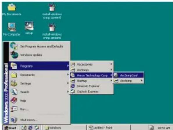
SNMP Community Configurations
About community, Community name acts as a password to screen accesses to the SNMP agent of a particular network device. Type in the community names of the SNMP agent.
Before access is granted to a request station, this station must incorporate a valid community name into its request; otherwise, the SNMP agent will deny access to the system. Most network devices use "public" as default of their community names. This value is case-sensitive.
SNMP Trap Notification Configurations
The "Community Name" should be the same as firmware-embedded SNMP Community. The "SNMP Trap Notification Configurations" includes level 1: Serious, level 2: Error, level 3: Warning and level 4: Information. The level 4 covers notification events such as initialization of the controller and initiation of the rebuilding process; Level 3 includes events which require the issuance of warning messages; Level 2 covers notification events which once have happen; Level 1 is the highest level, and covers events the need immediate attention (and action) from the administrator.

C-3-3-2 Linux
You must have administrative level permission to install Areca RAID software. This procedure assumes that the Areca RAID hardware and Linux are installed and operational in your system. The old version agent has to modify the open source project, integrate the changes from Areca manually, then take the modified binaries and manually deploy them. Users need to change source code from the linux distribution and then maintain it by themselves.
The new version agent provides the way to integrate with those codes into snmpd/snmptrapd and create a sub agent for user easy to install it. The new version SNMP extension agent installation for Linux procedure, please refer to
C-3-3-3 FreeBSD
You must have administrative level permission to install Areca RAID software. This procedure assumes that the Areca RAID hardware and FreeBSD are installed and operational in your system. The old version agent has to modify the open source project, integrate the changes from Areca manually, then take the modified binaries and manually deploy them. Users need to change source code from the linux distribution and then maintain it by themselves.
The new version agent provides the way to integrate with those codes into snmpd/snmptrapd and create a sub agent for user easy to install it. The new version SNMP extension agent installation for FreeBSD procedure, please refer to
Appendix D
Event Notification Configurations
The controller classifies disk array events into four levels depending on their severity. These include level 1: Urgent, level 2: Serious, level 3: Warning and level 4: Information. The level 4 covers notification events such as initialization of the controller and initiation of the rebuilding process; Level 2 covers notification events which once have happen; Level 3 includes events which require the issuance of warning messages; Level 1 is the highest level, and covers events that need immediate attention (and action) from the administrator. The following lists sample events for each level:
A. Device Event
| Event Level Meaning Action | |||
| Device Inserted Warning HDD inserted | |||
| Device Removed Warning HDD removed | |||
| Reading Error Warning HDD reading error Keep Watch | Watching HDD status, may be it caused by noise or HDD unstable. | ||
| Writing Error Warning HDD writing error Keep Watching HDD status, may be it caused by noise or HDD unstable. | |||
| ATA Ecc Error Warning HDD BCC error Keep Watching HDD status, may be it caused by noise or HDD unstable. | |||
| Change ATA Mode | Warning HDD change ATA mode | Check HDD connection | |
| Time Out Error | Warning | HDD time out | Keep Watching HDD status, may be it caused by noise or HDD unstable. |
| Device Failed | Urgent | HDD failure | Replace HDD |
| PCI Parity Error Serious PCI parity error If only happen once, it may be caused by noise. If always happen, please check power supply or contact to us. | |||
| Device Failed(SMART) | Urgent | HDD SMART failure | Replace HDD |
| PassThrough Disk Created | Inform | Pass Through Disk created | |
| PassThrough Disk Modified | Inform | Pass Through Disk modified | |
| PassThrough Disk Deleted | Inform | Pass Through Disk deleted | |
B. Volume Event
| Event Level Meaning Action | |||
| Start Initialize Warning Volume initialization has started | |||
| Start Rebuilding Warning Volume rebuilding has started | |||
| Start Migrating Warning Volume migration has started | |||
| Start Checking Warning Volume parity checking has started | |||
| Complete Init Warning Volume initialization completed | |||
| Complete Rebuild Warning Volume rebuilding completed | |||
| Complete Migrate Warning Volume migration completed | |||
| Complete Check Warning Volume parity checking completed | |||
| Create Volume Warning New volume created | |||
| Delete Volume Warning Volume deleted | |||
| Modify Volume Warning Volume modified | |||
| Volume Degraded Urgent Volume degraded Replace HDD | |||
| Volume Failed Urgent Volume failure | |||
| Failed Volume Revived Urgent Failed volume revived | |||
| Abort Initialization Warning Initialization been abort | |||
| Abort Rebuilding Warning Rebuilding aborted | |||
| Abort Migration Warning Migration aborted | |||
| Abort Checking Warning Parity check aborted | |||
| Stop Initialization Warning Initialization stopped | |||
| Stop Rebuilding Warning Rebuilding stopped | |||
| Stop Migration Warning Migration stopped | |||
| Stop Checking Warning Parity check stopped | |||
C. RAID Set Event
| Event Level Meaning Action | |||
| Create RaidSet Warning | New | RAID set created | |
| Delete RaidSet Warning | Raidset deleted | ||
| Expand RaidSet Warning | Raidset expanded | ||
| Rebuild RaidSet Warning | Raidset rebuilding | ||
| RaidSet Degraded | Urgent Raidset degraded Replace HDD | ||
D. Hardware Monitor Event
| Event Level Meaning Action | |||
| DRAM 1-Bit ECC | Urgent | DRAM 1-Bit ECC error | Check DRAM |
| DRAM Fatal Error | Urgent DRAM fatal error encountered | Check the DRAM module and replace with new one if required. | |
| Controller Over Temperature | Urgent Abnormally high temperature detected on controller | Check air flow and cooling fan of the enclosure, and contact us. | |
| Hdd Over Temperature | Urgent Abnormally high temperature detected on Hdd (over 55 degree) | Check air flow and cooling fan of the enclosure. | |
| Fan Failed | Urgent Cooling Fan # failure or speed below 1700RPM | Check cooling fan of the enclosure and replace with a new one if required. | |
| Controller Temp. Recovered | Serious | Controller temperature back tonormal level | |
| Hdd Temp. Recovered | Serious | Hdd temperature back tonormal level | |
| Raid Powered On | Warning | RAID power on | |
| Test Event | Urgent | Test event | |
| Power On With Battery Backup | Warning | RAID power on with battery backuped | |
| Incomplete RAID Discovered | Serious | Some RAID set member disks missing before power on | Check disk information to find out which channel missing. |
| HTTP Log In Serious | us a HTTP | login detected | |
| Telnet Log Serious | us a Telnet | login detected | |
| API Log In Serious | us a API login | in detected | |
| Lost Rebuilding/MigrationLBA | Urgent Some rebuilding/migration raidset member disks missing before power on. | Reinserted the missing member disk back, controller will continued the incomplete rebuilding/migration. | |
Appendix E
RAID Concept
RAID Set
A RAID set is a group of disks connected to a RAID controller. A RAID set contains one or more volume sets. The RAID set itself does not define the RAID level (0, 1, 1E, 3, 5, 6, 10, 30, 50 60, etc); the RAID level is defined within each volume set. Therefore, volume sets are contained within RAID sets and RAID Level is defined within the volume set. If physical disks of different capacities are grouped together in a RAID set, then the capacity of the smallest disk will become the effective capacity of all the disks in the RAID set.
Volume Set
Each volume set is seen by the host system as a single logical device (in other words, a single large virtual hard disk). A volume set will use a specific RAID level, which will require one or more physical disks (depending on the RAID level used). RAID level refers to the level of performance and data protection of a volume set. The capacity of a volume set can consume all or a portion of the available disk capacity in a RAID set. Multiple volume sets can exist in a RAID set. For the RAID controller, a volume set must be created either on an existing RAID set or on a group of available individual disks (disks that are about to become part of a RAID set). If there are pre-existing RAID sets with available capacity and enough disks for the desired RAID level, then the volume set can be created in the existing RAID set of the user's choice.
RAID set 1 (3 Individual Disks)
Disk 0

Disk 1
Disk 2
Free Space
Volume 1 (RAID 5)
Volume 0 (1E)
In the illustration, volume 1 can be assigned a RAID level 5 of operation while volume 0 might be assigned a RAID level 1E of operation. Alternatively, the free space can be used to create volume 2, which could then be set to use RAID level 5.
Ease of Use Features
- Foreground Availability/Background Initialization
RAID 0 and RAID 1 volume sets can be used immediately after creation because they do not create parity data. In Background Initialization, the initialization proceeds as a background task, and the volume set is fully accessible for system reads and writes. The operating system can instantly access the newly created arrays without requiring a reboot and without waiting for initialization to complete. Furthermore, the volume set is protected against disk failures while initialing. If using Foreground Initialization, the initialization process must be completed before the volume set is ready for system accesses.
• Online Array Roaming
RAID controllers store RAID configuration information on the disk drives. The controller therefore protects the configuration settings in the event of controller failure. Online array roaming allows the administrators the ability to move a complete RAID set to another system without losing RAID configuration information or data on that RAID set. Therefore, if a server fails, the RAID set disk drives can be moved to another server with an Areca RAID controllers and the disks can be inserted in any order.
• Online Capacity Expansion
Online Capacity Expansion makes it possible to add one or more physical drives to a volume set without interrupting server operation, eliminating the need to backup and restore after reconfiguration of the RAID set. When disks are added to a RAID set, unused capacity is added to the end of the RAID set. Then, data on the existing volume sets (residing on
the newly expanded RAID set) is redistributed evenly across all the disks. A contiguous block of unused capacity is made available on the RAID set. The unused capacity can be used to create additional volume sets.
A disk, to be added to a RAID set, must be in normal mode (not failed), free (not spare, in a RAID set, or passed through to host) and must have at least the same capacity as the smallest disk capacity already in the RAID set.
Capacity expansion is only permitted to proceed if all volumes on the RAID set are in the normal status. During the expansion process, the volume sets being expanded can be accessed by the host system. In addition, the volume sets with RAID level 1 is protected against data loss in the event of disk failure(s). In the case of disk failure, the volume set changes from "migrating" state to "migrating+degraded" state. When the expansion is completed, the volume set would then transition to "degraded" mode. If a global hot spare is present, then it further changes to the "rebuilding" state.
The expansion process is illustrated as following figure.
Before Array Expansion
Disk 0 40 GB
Disk 1
40 GB

Disk 2
40 GB
Free Space = 40GB
Volume 1 = 40GB(D:)
Volume 0 = 40GB(C:)
Array-A 120GB
RAID controller redistributes the original volume set over the original and newly added disks, using the same fault-tolerance configuration. The unused capacity on the expand RAID set can then be used to create an additional volume set, with a different fault tolerance setting (if required by the user.)
After Array Expansion (Adding One Disk)

Disk 0
40 GB

Disk 1
40 GB
Disk 2
40 GB
Disk 3
40 GB
Free Space = 80GB
Volume 1 = 40GB(D:)
Volume 0 = 40GB(C:)
Array-A 160GB
• Online RAID Level and Stripe Size Migration
For those who wish to later upgrade to any RAID capabilities, a system with online RAID level/stripe size migration allows a simplified upgrade to any supported RAID level without having to reinstall the operating system.
The RAID controllers can migrate both the RAID level and stripe size of an existing volume set, while the server is on-line and the volume set is in use. Online RAID level/stripe size migration can prove helpful during performance tuning activities as well as when additional physical disks are added to the RAID controller. For example, in a system using two drives in RAID level 1, it is possible to add a single drive and add capacity and retain fault tolerance. (Normally, expanding a RAID level 1 array would require the addition of two disks). A third disk can be added to the existing RAID logical drive and the volume set can then be migrated from RAID level 1 to 5. The result would be parity fault tolerance and double the available capacity without taking the system down. A forth disk could be added to migrate to RAID level 6. It is only possible to migrate to a higher RAID level by adding a disk; disks in an existing array can't be reconfigured for a higher RAID level without adding a disk.
Online migration is only permitted to begin, if all volumes to be migrated are in the normal mode. During the migration process, the volume sets being migrated are accessed by the host system. In addition, the volume sets with RAID level 1 is protected against data loss in the event of disk failure(s). In
the case of disk failure, the volume set transitions from migrating state to (migrating+degraded) state. When the migration is completed, the volume set transitions to degraded mode. If a global hot spare is present, then it further transitions to rebuilding state.
• Online Volume Expansion
Performing a volume expansion on the controller is the process of growing only the size of the latest volume. A more flexible option is for the array to concatenate an additional drive into the RAID set and then expand the volumes on the fly. This happens transparently while the volumes are online, but, at the end of the process, the operating system will detect free space at after the existing volume.
Windows, NetWare and other advanced operating systems support volume expansion, which enables you to incorporate the additional free space within the volume into the operating system partition. The operating system partition is extended to incorporate the free space so it can be used by the operating system without creating a new operating system partition.
You can use the Diskpart.exe command line utility, included with Windows Server 2003 or the Windows 2000 Resource Kit, to extend an existing partition into free space in the dynamic disk.
Third-party software vendors have created utilities that can be used to repartition disks without data loss. Most of these utilities work offline. Partition Magic is one such utility.
High Availability
- Global/Local Hot Spares
A hot spare is an unused online available drive, which is ready for replacing the failure disk. The hot spare is one of the most important features that RAID controllers provide to deliver a high degree of fault-tolerance. A hot spare is a spare physical drive that has been marked as a hot spare and therefore
is not a member of any RAID set. If a disk drive used in a volume set fails, then the hot spare will automatically take its place and he data previously located on the failed drive is reconstructed on the hot spare.
Dedicated hot spare is assigned to serve one specified RAID set. Global hot spare is assigned to serve all RAID set on the RAID controller. Dedicated hot spare has higher priority than the global hot spare. For this feature to work properly, the hot spare must have at least the same capacity as the drive it replaces. The host spare function only works with RAID level 1 volume set.
The "Create Hot Spare" option gives you the ability to define a global/dedicated hot spare disk drive. To effectively use the hot spare feature, you must always maintain at least one drive that is marked as a global hot spare.
Important:
The hot spare must have at least the same capacity as the drive it replaces.
• Hot-Swap Disk Drive Support
The RAID controller chip includes a protection circuit that supports the replacement of SATA hard disk drives without having to shut down or reboot the system. A removable hard drive tray can deliver "hot swappable" fault-tolerant RAID solutions. This feature provides advanced fault tolerant RAID protection and "online" drive replacement.
• Auto Declare Hot-Spare
If a disk drive is brought online into a system operating in degraded mode, the RAID controllers will automatically declare the new disk as a spare and begin rebuilding the degraded volume. The Auto Declare Hot-Spare function requires that the smallest drive contained within the volume set in which the failure occurred.
In the normal status, the newly installed drive will be reconfigured an online free disk. But, the newly-installed drive is automatically assigned as a hot spare if any hot spare disk was used to rebuild and without new installed drive replaced it. In this condition, the Auto Declare Hot-Spare status will be disappeared if the RAID subsystem has since powered off/on.
The Hot-Swap function can be used to rebuild disk drives in arrays with data redundancy such as RAID level 1, 1E, 3, 5, 6, 10, 30, 50 and 60.
- Auto Rebuilding
If a hot spare is available, the rebuild starts automatically when a drive fails. The RAID controllers automatically and transparently rebuild failed drives in the background at user-definable rebuild rates.
If a hot spare is not available, the failed disk drive must be replaced with a new disk drive so that the data on the failed drive can be automatically rebuilt and so that fault tolerance can be maintained.
RAID controllers will automatically restart the system and rebuilding process if the system is shut down or powered off abnormally during a reconstruction procedure condition.
When a disk is hot swapped, although the system is functionally operational, the system may no longer be fault tolerant. Fault tolerance will be lost until the removed drive is replaced and the rebuild operation is completed.
During the automatic rebuild process, system activity will continue as normal, however, the system performance and fault tolerance will be affected.
- Adjustable Rebuild Priority
Rebuilding a degraded volume incurs a load on the RAID subsystem. The RAID controllers allow the user to select the rebuild priority to balance volume access and rebuild tasks
appropriately. The Background Task Priority is a relative indication of how much time the controller devotes to a background operation, such as rebuilding or migrating.
RAID controller allows user to choose the task priority (Ultra Low (5%), Low (20%), Medium (50%), High (80%)) to balance volume set access and background tasks appropriately. For high array performance, specify an Ultra Low value. Like volume initialization, after a volume rebuilds, it does not require a system reboot.
High Reliability
- Hard Drive Failure Prediction
In an effort to help users avoid data loss, disk manufacturers are now incorporating logic into their drives that acts as an "early warning system" for pending drive problems. This system is called SMART. The disk integrated controller works with multiple sensors to monitor various aspects of the drive's performance, determines from this information if the drive is behaving normally or not, and makes available status information to 6Gb/s SATA RAID controller firmware that probes the drive and look at it.
The SMART can often predict a problem before failure occurs. The controllers will recognize a SMART error code and notify the administer of an impending hard drive failure.
• Auto Reassign Sector
Under normal operation, even initially defect-free drive media can develop defects. This is a common phenomenon. The bit density and rotational speed of disks is increasing every year, and so are the potential of problems. Usually a drive can internally remap bad sectors without external help using cyclic redundancy check (CRC) checksums stored at the end of each sector.
The RAID controller drives perform automatic defect re-assignment for both read and write errors. Writes are always
completed - if a location to be written is found to be defective, the drive will automatically relocate that write command to a new location and map out the defective location. If there is a recoverable read error, the correct data will be transferred to the host and that location will be tested by the drive to be certain the location is not defective. If it is found to have a defect, data will be automatically relocated, and the defective location is mapped out to prevent future write attempts.
In the event of an unrecoverable read error, the error will be reported to the host and the location will be flagged as being potentially defective. A subsequent write to that location will initiate a sector test and relocation should that location prove to have a defect. Auto Reassign Sector does not affect disk subsystem performance because it runs as a background task. Auto Reassign Sector discontinues when the operating system makes a request.
Data Protection
- Battery Backup
The RAID controllers are armed with a Battery Backup Module (BBM). While a Uninterruptible Power Supply (UPS) protects most servers from power fluctuations or failures, a BBM provides an additional level of protection. In the event of a power failure, a BBM supplies power to retain data in the RAID controller's cache, thereby permitting any potentially dirty data in the cache to be flushed out to secondary storage when power is restored.
The batteries in the BBM are recharged continuously through a trickle-charging process whenever the system power is on. The batteries protect data in a failed server for up to three or four days, depending on the size of the memory module. Under normal operating conditions, the batteries last for three years before replacement is necessary.
- Recovery ROM
RAID controller firmware is stored on the flash ROM and is executed by the I/O processor. The firmware can also be updated through the RAID controllers PCIe 2.0 bus port or Ethernet port without the need to replace any hardware chips. During the controller firmware upgrade flash process, it is possible for a problem to occur resulting in corruption of the controller firmware. With our Redundant Flash Image feature, the controller will revert back to the last known version of firmware and continue operating. This reduces the risk of system failure due to firmware crash.
Appendix F
Understanding RAID
RAID is an acronym for Redundant Array of Independent Disks. It is an array of multiple independent hard disk drives that provides high performance and fault tolerance. The RAID controller implements several levels of the Berkeley RAID technology. An appropriate RAID level is selected when the volume sets are defined or created. This decision should be based on the desired disk capacity, data availability (fault tolerance or redundancy), and disk performance. The following section discusses the RAID levels supported by the RAID controller.
The RAID controllers makes the RAID implementation and the disks' physical configuration transparent to the host operating system. This means that the host operating system drivers and software utilities are not affected, regardless of the RAID level selected. Correct installation of the disk array and the controller requires a proper understanding of RAID technology and the concepts.
RAID 0
RAID 0, also referred to as striping, writes stripes of data across multiple disk drives instead of just one disk drive. RAID 0 does not provide any data redundancy, but does offer the best High-speed data throughput. RAID 0 breaks up data into smaller blocks and then writes a block to each drive in the array. Disk striping enhances performance because multiple drives are accessed simultaneously; the reliability of RAID level 0 is less because the entire array will fail if any one disk drive fails.
![graph TD A["Array Management"] --> B["RAID 0 : Striping"] B --> C1["Block 1"] B --> C2["Block 2"] B --> C3["Block 3"] C1 --> D1["Disk 1"] C1 --> D2["Disk 2"] C2 --> D3["Disk 3"] C2 --> D4["Disk 4"] C3 --> D3 style A fill:#f9f,stroke:#333 style B fill:#ccf,stroke:#333](/content/2026/05/990737/images/2ed32e7f176a6167316747759445736679c9654a2c46d20ed84a62007244a814.jpg)
RAID 1
RAID 1 is also known as “disk mirroring”; data written on one disk drive is simultaneously written to another disk drive. Read performance will be enhanced if the array controller can, in parallel, access both members of a mirrored pair. During writes, there will be a minor performance penalty when compared to writing to a single disk. If one drive fails, all data (and software applications) are preserved on the other drive. RAID 1 offers extremely high data reliability, but at the cost of doubling the required data storage capacity.
![graph TD A["Array Management"] --> B["Logical disk"] B --> C["Block 0"] C --> D["A0"] C --> E["B0"] C --> F["C0"] C --> G["D0"] D --> H["Disk 1"] E --> I["Disk 2"] J["RAID1: Mirroring"] --> K["Block 0"] K --> L["="] L --> M["A0"] L --> N["B0"] L --> O["C0"] L --> P["D0"] M --> Q["Disk 2"] N --> R["D…](/content/2026/05/990737/images/7c0c8f067735f666e34908bf3269e93f48c4f296d54822b1e3be005521cd6e92.jpg)
JBOD
(Just a Bunch Of Disks) A group of hard disks in a RAID box are not set up as any type of RAID configuration. All drives are available to the operating system as an individual disk. JBOD does not provide data redundancy.
Single Disk (Pass-Through Disk)
Pass through disk refers to a drive that is not controlled by the RAID firmware and thus can not be a part of a RAID volume. The drive is available to the operating system as an individual disk.
Summary of RAID Levels
6Gb/s SATA RAID controller supports RAID Level 0 and 1. The following table provides a summary of RAID levels.
| RAID Level Comparison | |||
| RAID Level | Description | Disks Requirement (Minimum) | Data Availability |
| 0 | Also known as striping.Data distributed across multiple drives in the array. There is no data protection. | 1 | No data Protection |
| 1 | Also known as mirroring.All data replicated on 2 separated disks.N is almost always 2. Due to this is a 100 % duplication, so is a high costly solution. | 2 | Up to one disk failure |
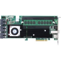
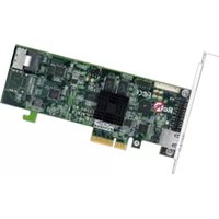
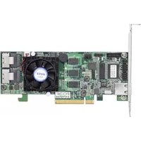
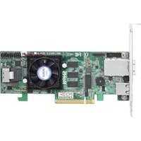

- COPYRIGHT AND TRADEMARKS
- FCC STATEMENT
- MANUFACTURER'S DECLARATION FOR CE CERTIFICATION
- CONTENTS
- INTRODUCTION......10
- HARDWARE INSTALLATION .... 14
- MCBIOS RAID MANAGER 29
- DRIVER INSTALLATION....83
- ARCHTTP PROXY SERVER INSTALLATION 94
- WEB BROWSER-BASED CONFIGURATION 104
- 6.8.3 HDD POWER MANAGEMENT....135
- 6.8.4 VIEW EVENTS/MUTE BEEPER 136
- 6.9 INFORMATION....139
- APPENDIX A 141
- UPGRADING FLASH ROM UPDATE PROCESS.... 141
- APPENDIX B 145
- BATTERY BACKUP MODULE (ARC-6120BA-T121-12G)....145
- APPENDIX C 149
- SNMP OPERATION & INSTALLATION 149
- APPENDIX D....159
- APPENDIX E 163
- RAID CONCEPT 163
- RAID SET 163
- INTRODUCTION
- 1.1 OVERVIEW
- UNPARALLELED PERFORMANCE
- UNSURPASSED DATA AVAILABILITY
- MAXIMUM INTEROPERABILITY
- EASY RAID MANAGEMENT
- 1.2 FEATURES
- CONTROLLER ARCHITECTURE
- RAID FEATURES
- MONITORS/NOTIFICATION
- RAID MANAGEMENT
- IN-BAND MANAGER
- OUT-OF-BAND MANAGER
- OPERATING SYSTEM
- NOTE
- HARDWARE INSTALLATION
- 2.1 BEFORE YOU FIRST INSTALLING
- PACKAGE CONTENTS
- 2.2 BOARD LAYOUT
- TOOLS REQUIRED
- SYSTEM REQUIREMENT
- INSTALLATION TOOLS
- PERSONAL SAFETY INSTRUCTIONS
- ELECTROSTATIC DISCHARGE
- WARNING
- 2.3 INSTALLATION
- STEP 1. UNPACK
- STEP 2. POWER PC/SERVER OFF
- STEP 3. INSTALL THE PCIE 6GB/S SATA RAID CARDS
- STEP 4. MOUNT THE DRIVES
- STEP 5. CONNECT THE SATA CABLE
- STEP 6. INSTALL THE LED CABLE (OPTIONAL)
- A: INDIVIDUAL FAULT LED AND GLOBAL ACTIVITY/FAULT INDICATOR CONNECTOR
- B: ARECA SERIAL BUS CONNECTOR
- STEP 7. ADDING A BATTERY BACKUP MODULE (OPTIONAL)
- STEP 8. RE-CHECK FAULT LED CABLE CONNECTIONS (OPTIONAL)
- STEP 9. POWER UP THE SYSTEM
- STEP 10. INSTALL THE CONTROLLER DRIVER
- FOR A NEW SYSTEM
- FOR AN EXISTING SYSTEM
- STEP 11. INSTALL ARCHTTP PROXY SERVER
- STEP 12. CONFIGURE VOLUME SET
- STEP 13. FORMAT, PARTITION AND MOUNT THE ARC-1203-2I RAID CONTROLLER VOLUMES
- STEP 14. DETERMINING THE BOOT SEQUENCES
- FOR PC SYSTEM
- FOR APPLE MAC PRO SYSTEM
- 2.4 SUMMARY OF THE INSTALLATION
- MCRAID STORAGE MANAGER
- ARCHTTP PROXY SERVER
- CLI UTILITY
- SNMP MANAGER CONSOLE INTEGRATION
- IN-BAND-USING PCIE HOST BUS INTERFACE
- SINGLE ADMIN PORTAL (ARCSAP) MONITOR
- MCBIOS RAID MANAGER
- 3.1 STARTING THE MCBIOS RAID MANAGER
- 3.2 MCBIOS RAID MANAGER
- 3.3 CONFIGURING RAID SETS AND VOLUME SETS
- 3.4 DESIGNATING DRIVES AS HOT SPARES
- 3.5 USING QUICK VOLUME /RAID SETUP CONFIGURATION
- 3.6 USING RAID SET/VOLUME SET FUNCTION METHOD
- 3.7 MAIN MENU
- 3.7.1 QUICK VOLUME/RAID SETUP
- NO
- USE 64BIT LBA
- USE 4K BLOCK
- 3.7.2 RAID SET FUNCTION
- 3.7.2.1 CREATE RAID SET
- 3.7.2.2 DELETE RAID SET
- 3.7.2.3 EXPAND RAID SET
- CAUTION
- MIGRATING
- 3.7.2.4 OFFLINE RAID SET
- 3.7.2.5 ACTIVATE INCOMPLETE RAID SET
- 3.7.2.6 CREATE HOT SPARE
- 3.7.2.7 DELETE HOT SPARE
- 3.7.2.8 RESCUE RAID SET
- 3.7.2.9 RAID SET INFORMATION
- 3.7.3 VOLUME SET FUNCTION
- 3.7.3.1 CREATE VOLUME SET (0/1)
- VOLUME NAME
- RAID LEVEL
- CAPACITY
- STRIPE SIZE
- SCSI ID
- SCSI LUN
- CACHE MODE
- WRITE PROTECT
- TAG QUEUING
- 3.7.3.2 DELETE VOLUME SET
- 3.7.3.3 MODIFY VOLUME SET
- 3.7.3.3.1 VOLUME GROWTH
- TO EXPAND AN EXISTING VOLUME NOTICED
- FOR GREATER 2TB EXPANSION
- 3.7.3.3.2 VOLUME SET MIGRATION
- 3.7.3.4 CHECK VOLUME SET
- 3.7.3.5 STOP VOLUME SET CHECK
- 3.7.3.6 DISPLAY VOLUME SET INFO
- 3.7.4 PHYSICAL DRIVES
- 3.7.4.1 VIEW DRIVE INFORMATION
- 3.7.4.2 CREATE PASS-THROUGH DISK
- 3.7.4.3 MODIFY PASS-THROUGH DISK
- 3.7.4.4 DELETE PASS-THROUGH DISK
- 3.7.4.5 SET DISK TO BE FAILED
- 3.7.4.6 ACTIVATE FAILED DISK
- 3.7.4.7 IDENTIFY SELECTED DRIVE
- 3.7.4.8 IDENTIFY ENCLOSURE
- 3.7.5 RAID SYSTEM FUNCTION
- 3.7.5.1 MUTE THE ALERT BEEPER
- 3.7.5.2 ALERT BEEPER SETTING
- 3.7.5.3 CHANGE PASSWORD
- THE MANUFACTURE DEFAULT PASSWORD IS SET TO 0000
- 3.7.5.4 JBOD/RAID FUNCTION
- 3.7.5.5 BACKGROUND TASK PRIORITY
- 3.7.5.6 SATA NCQ SUPPORT
- 3.7.5.7 HDD READ AHEAD CACHE
- 3.7.5.8 VOLUME DATA READ AHEAD
- 3.7.5.9 EMPTY HDD SLOT LED
- 3.7.5.10 AUTO ACTIVATE RAID SET
- 3.7.5.11 DISK WRITE CACHE MODE
- 3.7.5.12 WRITE SAME SUPPORT
- 3.7.5.13 CAPACITY TRUNCATION
- 3.7.6 MORE SYSTEM FUNCTIONS
- 3.7.6.1 SMART OPTION FOR HDD
- 3.7.6.2 SMART POLLING INTERVAL
- 3.7.6.3 HOT PLUGGED DISK FOR REBUILDING
- 3.7.7 HDD POWER MANAGEMENT
- 3.7.7.1 STAGGER POWER ON
- 3.7.7.2 TIME TO HDD LOW POWER IDLE
- 3.7.7.3 TIME TO LOW RPM MODE
- 3.7.7.4 TIME TO SPIN DOWN IDLE HDD
- 3.7.8 ALERT BY MAIL CONFIG
- 3.7.9 VIEW SYSTEM EVENTS
- 3.7.10 CLEAR EVENTS BUFFER
- 3.7.11 HARDWARE MONITOR
- 3.7.12 SYSTEM INFORMATION
- DRIVER INSTALLATION
- INSTALLING OPERATING SYSTEM ON SATA CONTROLLER'S VOLUME
- INSTALLING SATA RAID CONTROLLER INTO AN EXISTING OPERATING SYSTEM
- 4.1 CREATING THE DRIVER DISK
- 4.2 DRIVER INSTALLATION FOR WINDOWS
- 4.2.1 INSTALLING WINDOWS ON A RAID VOLUME
- 4.2.2 INSTALLING CONTROLLER ON AN EXISTING WINDOWS
- 4.2.3 UNINSTALL CONTROLLER FROM WINDOWS
- 4.3 DRIVER INSTALLATION FOR LINUX
- 4.4 DRIVER INSTALLATION FOR FREEBSD
- 4.5 DRIVER INSTALLATION FOR SOLARIS
- 4.6 DRIVER INSTALLATION FOR MAC X
- 4.6.1 INSTALLATION PROCEDURES
- IMPORTANT
- 4.6.2 MAKING VOLUME SETS AVAILABLE TO MAC OS X
- TO INITIALIZE AND PARTITION YOUR UNIT
- ARCHTTP PROXY SERVER INSTALLATION
- OVERVIEW
- 5.1 FOR WINDOWS
- 5.2 FOR LINUX
- FOR MOZILLA USER
- 5.3 FOR FREEBSD
- 5.4 FOR SOLARIS 10
- 5.5 FOR MAC OS X
- 5.6 ARCHTTP CONFIGURATION
- GENERAL CONFIGURATION
- MAIL (ALERT BY MAIL) CONFIGURATION
- SMTP SERVER CONFIGURATION
- MAIL ADDRESS CONFIGURATIONS
- EVENT NOTIFICATION CONFIGURATIONS
- SNMP TRAPS CONFIGURATION
- SNMP TRAP CONFIGURATIONS
- SNMP SYSTEM CONFIGURATIONS
- SNMP TRAP NOTIFICATION CONFIGURATIONS
- RESCAN DEVICE CONFIGURATION
- COLLECT SUPPORT DATA
- WEB BROWSER-BASED CONFIGURATION
- 6.1 START-UP MCRAID STORAGE MANAGER
- START-UP FROM WINDOWS/MAC LOCAL ADMINISTRATION
- START-UP FROM LOCAL ADMINISTRATION
- 6.2 MCRAID STORAGE MANAGER
- 6.3 MAIN MENU
- 6.4 QUICK FUNCTION
- 6.5 RAID SET FUNCTIONS
- 6.5.1 CREATE RAID SET
- 6.5.2 DELETE RAID SET
- RAID SET = 000 2/2 NORMAL 2000.0GB
- 6.5.3 EXPAND RAID SET
- 6.5.4 OFFLINE RAID SET
- RAID SET # 000 2/2 NORMAL 60.0GB
- 6.5.5 RENAME RAID SET
- 6.5.6 ACTIVATE INCOMPLETE RAID SET
- 6.5.7 CREATE HOT SPARE
- 6.5.8 DELETE HOT SPARE
- 6.5.9 RESCUE RAID SET
- 6.6 VOLUME SET FUNCTIONS
- 6.6.1 CREATE VOLUME SET (0/1)
- VOLUME RAID LEVEL
- GREATER TWO TB VOLUME SUPPORT
- 64BIT LBA
- 4K BLOCK
- INITIALIZATION MODE
- VOLUME WRITE PROTECTION
- TAGGED COMMAND QUEUING
- SCSI CHANNEL/SCSI ID/SCSI LUN
- 6.6.2 DELETE VOLUME SET
- 6.6.3 MODIFY VOLUME SET
- 6.6.3.1 VOLUME GROWTH
- 6.6.3.2 VOLUME SET MIGRATION
- 6.6.4 CHECK VOLUME SET
- 6.6.5 STOP VOLUME SET CHECK
- 6.7 PHYSICAL DRIVE
- 6.7.1 CREATE PASS-THROUGH DISK
- 6.7.2 MODIFY PASS-THROUGH DISK
- 6.7.3 DELETE PASS-THROUGH DISK
- 6.7.4 CLONE DISK
- CLONE DISK PROCEDURE
- 6.7.4.1 CLONE AND REPLACE
- 6.7.4.2 CLONE ONLY
- 6.7.5 ABORT CLONING
- 6.7.6 SET DISK TO BE FAILED
- 6.7.7 ACTIVATE FAILED DISK
- 6.7.8 IDENTIFY ENCLOSURE
- 6.7.9 IDENTIFY DRIVE
- 6.8 SYSTEM CONTROLS
- 6.8.1 SYSTEM CONFIG
- SYSTEM BEEPER SETTING
- BACKGROUND TASK PRIORITY
- JBOD/RAID CONFIGURATION
- SATA NCQ SUPPORT
- HDD READ AHEAD CACHE
- VOLUME DATA READ AHEAD
- EMPTY HDD SLOT LED
- MAX COMMAND LENGTH
- AUTO ACTIVATE INCOMPLETE RAID
- DISK WRITE CACHE MODE
- WRITE SAME FOR INITIALIZATION
- HOT PLUGGED DISK FOR REBUILDING
- DISK CAPACITY TRUNCATION MODE
- SMART OPTION FOR HDD
- SMART POLLING INTERVAL
- 6.8.2 ADVANCED CONFIGURATION
- TLER SETTING
- TIMEOUT SETTING
- NUMBER OF RETRIES
- BUFFER THRESHOLD
- AMOUNT OF READ AHEAD
- NUMBER OF AV STREAM
- OPTIMIZE AV RECORDING
- READ PERFORMANCE MARGIN
- WRITE PERFORMANCE MARGIN
- READ AND DISCARD PARITY DATA
- BIOS SELECTION
- BIOS OPTION
- 6.8.3 HDD POWER MANAGEMENT
- STAGGER POWER ON CONTROL
- TIME TO HDD LOW POWER IDLE
- TIME TO HDD LOW RPM MODE
- TIME TO SPIN DOWN IDLE HDD
- SATA POWER UP IN STANDBY
- 6.8.4 VIEW EVENTS/MUTE BEEPER
- 6.8.5 GENERATE TEST EVENT
- 6.8.6 CLEAR EVENTS BUFFER
- 6.8.7 MODIFY PASSWORD
- 6.8.8 UPDATE FIRMWARE
- 6.9 INFORMATION
- 6.9.1 RAID SET HIERARCHY
- 6.9.2 SYSTEM INFORMATION
- 6.9.3 HARDWARE MONITOR
- APPENDIX A
- UPGRADING FLASH ROM UPDATE PROCESS
- A-1 OVERVIEW
- A-2 UPGRADING FIRMWARE THROUGH MCRAID STORAGE MANAGER
- A-3 UPGRADING FIRMWARE THROUGH NFLASH DOS UTILITY
- STARTING THE NFLASH UTILITY
- A-4 UPGRADING FIRMWARE THROUGH CLI
- APPENDIX B
- BATTERY BACKUP MODULE (ARC-6120BA-T121-12G)
- B-1 OVERVIEW
- B-2 BBM COMPONENTS
- B-3 STATUS OF BBM
- B-4 INSTALLATION
- B-5 BATTERY BACKUP CAPACITY
- B-6 OPERATION
- B-7 CHANGING THE BATTERY BACKUP MODULE
- B-8 BATTERY FUNCTIONALITY TEST PROCEDURE
- B-9 BBM SPECIFICATIONS
- MECHANICAL
- ENVIRONMENTAL
- ELECTRICAL
- APPENDIX C
- SNMP OPERATION & INSTALLATION
- C-1 OVERVIEW
- C-2 SNMP DEFINITION
- C-3 SNMP INSTALLATION
- STEP 1. INSTALLING THE SNMP MANAGER SOFTWARE ON THE CLIENT
- STEP 2. COMPILING THE MIB DESCRIPTION FILE WITH THE MANAGEMENT
- STEP 3. SNMP SERVICE METHOD
- C-3-1 USING ARCHTTP
- C-3-2 USING IN-BAND PCIE + SNMP EXTENSION AGENT INSTALLATION
- C-3-3 SNMP EXTENSION AGENT INSTALLATION
- C-3-3-1 WINDOWS
- STARTING SNMP TRAP NOTIFICATION CONFIGURATIONS
- SNMP COMMUNITY CONFIGURATIONS
- C-3-3-2 LINUX
- C-3-3-3 FREEBSD
- APPENDIX D
- APPENDIX E
- RAID CONCEPT
- RAID SET
- VOLUME SET
- EASE OF USE FEATURES
- FOREGROUND AVAILABILITY/BACKGROUND INITIALIZATION
- ONLINE ARRAY ROAMING
- ONLINE CAPACITY EXPANSION
- ONLINE RAID LEVEL AND STRIPE SIZE MIGRATION
- ONLINE VOLUME EXPANSION
- HIGH AVAILABILITY
- GLOBAL/LOCAL HOT SPARES
- HOT-SWAP DISK DRIVE SUPPORT
- AUTO DECLARE HOT-SPARE
- AUTO REBUILDING
- ADJUSTABLE REBUILD PRIORITY
- HIGH RELIABILITY
- HARD DRIVE FAILURE PREDICTION
- AUTO REASSIGN SECTOR
- DATA PROTECTION
- BATTERY BACKUP
- RECOVERY ROM
- APPENDIX F
- UNDERSTANDING RAID
- RAID 0
- RAID 1
- JBOD
- SINGLE DISK (PASS-THROUGH DISK)
- SUMMARY OF RAID LEVELS
Brand : Areca
Model : ARC-1203-2I
Category : Controller