
230V 150L - Compressor Draper - Free user manual and instructions
Find the device manual for free 230V 150L Draper in PDF.


| Product Type | Air Compressor |
| Brand | Draper |
| Model | 230V 150L |
| Rated Voltage | 230V ~ 50Hz |
| Rated Input Power | 2200W (3.0 HP) |
| Max Working Pressure | 145 PSI / 10 Bar |
| Air Displacement | 12.9 cfm / 365 L/min |
| Free Air Delivered (FAD) | 8.3 cfm / 234 L/min |
| Receiver Capacity | 150 Litres |
| Sound Pressure Level | 79.0 dB(A) |
| Sound Power Level | 94.0 dB(A) |
| Dimensions (L x W x H) | 1330 x 500 x 890 mm |
| Weight | 97.5 kg |
| Speed (No Load) | 1,375 r/min |
| Oil Type | ISO 100 viscosity compressor oil (e.g., Castrol Aircol PD100) |
| Overload Protection | Thermal cut-out with manual reset |
| Safety Valve | Overload safety relief valve |
| Condensate Drain | Drain bung under tank |
| Warranty | 12 months from purchase date |
| Noise Protection | Wear safety goggles and ear defenders |
Frequently Asked Questions - 230V 150L Draper
User questions about 230V 150L Draper
0 question about this device. Answer the ones you know or ask your own.
Ask a new question about this device
Download the instructions for your Compressor in PDF format for free! Find your manual 230V 150L - Draper and take your electronic device back in hand. On this page are published all the documents necessary for the use of your device. 230V 150L by Draper.
USER MANUAL 230V 150L Draper
IMPORTANT: PLEASE READ THESE INSTRUCTIONS CAREFULLY TO ENSURE THE SAFE AND EFFECTIVE USE OF THIS PRODUCT.
natural_image
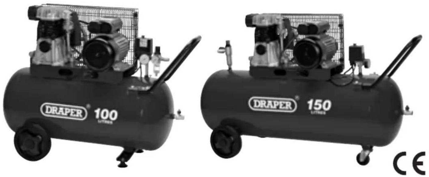
Two DRAPER 100 and 150 air conditioners with visible propellers and wheels, no text or symbols on the equipment themselves.DRAPER
GENERAL INFORMATION
Read all these instructions before operating this product and save these instructions.
This manual has been compiled by Draper Tools and is an integrated part of the product with which it is enclosed and should be kept with it for future references.
This manual describes the purpose for which the product has been designed and contains all the necessary information to ensure its correct and safe use. We recommend that this manual is read before any operation or, before performing any kind of adjustment to the product and prior to any maintenance tasks. By following all the general safety instructions contained in this manual, it will ensure both product and operator safety, together with longer life of the product itself.
All photographs and drawings in this manual are supplied by Draper Tools to help illustrate the operation of the product.
Whilst every effort has been made to ensure accuracy of information contained in this manual, the Draper Tools policy of continuous improvement determines the right to make modifications without prior warning.

CONTENTS
Contents/Guarantee 1
Specification 2
Power supply 3
General safety instructions 4
Additional safety instructions 5
Getting to know your air compressor 6
Assembly 7
Operation and use 8-9
Maintenance 10-11
Troubleshooting 12
Disposal 13
Explanation of symbols/pictograms 13
Declaration enclosed

GUARANTEE
Draper tools have been carefully tested and inspected before shipment and are guaranteed to be free from defective materials and workmanship for a period of 12 months from the date of purchase except where tools are hired out when the guarantee period is ninety days from the date of purchase.
A proof of purchase must be provided with the tool.
Should the machine develop any fault, please return the complete tool to your nearest authorized warranty repair agent or contact Draper Tools Limited, Chandler's Ford, Eastleigh, Hampshire, SO53 1YF. England. Telephone Sales Desk: (023) 8049 4333 or Product Helpline (023) 8049 4344.
If upon inspection it is found that the fault occurring is due to defective materials or workmanship, repairs will be carried out free of charge. This guarantee does not apply to normal wear and tear, nor does it cover any damage caused by misuse, careless or unsafe handling, alterations, accident, or repairs attempted or made by any personnel other than the authorised Draper warranty repair agent.
NOTE: If the tool is found not to be within the terms of warranty, repairs and carriage charges will be quoted and made accordingly.
This guarantee applies in lieu of any other guarantee expressed or implied and variations of its terms are not authorised.
Your Draper guarantee is not effective unless you can produce upon request a dated receipt or invoice to verify your proof of purchase within the 12 month period.
Please note that this guarantee is an additional benefit and does not affect your statutory rights.
Draper Tools Limited
The Draper Tools policy of continuous improvement determines the right to change specification without notice.
Stock nos. 03238 03239
Part nos. DA100/365B DA150/365B
Rated voltage....230V\~50Hz ....230V\~50Hz
Rated input 2200W (3.0HP) 2200W (3.0HP)
Speed (no load) 1,375r/min ^-1 1,375r/min ^-1
Maximum working pressure 145PSI/10Bar 145PSI/10Bar
Air displacement 12.9cfm/365L/min 12.9cfm/365L/min
Free air delivered (FAD) 8.3cfm/234L/min 8.3cfm/234L/min
Receiver capacity....100 Litres ....150 Litres
Sound pressure level 79.0dB(A) 79.0dB(A)
Sound power level 93.0dB(A) 94.0dB(A)
Dimensions (LxWxH) 1070x450x770 1330x500x890
Weight 61.5kg 97.5kg
WARNING: Always wear safety goggles and ear defenders.
POWER SUPPLY
CAUTION: Risk of electric shock. Do not open.
This appliance is supplied with a moulded 3 pin mains plug for your safety. The value of the fuse fitted is marked on the pin face of the plug. Should the fuse need replacing, ensure the substitute is of the correct rating, approved to BS1362 and ASTA or BS Kite marked.

The fuse cover is removable with a small plain slot screwdriver. Ensure the fuse cover is replaced before attempting to connect the plug to an electrical outlet. If the cover is missing, a replacement must be obtained or the plug replaced with a suitable type.
If a replacement plug is to be fitted this must be carried out by a qualified electrician.
The damaged or incomplete plug, when cut from the cable shall be disabled to prevent connection to a live electrical outlet.
This appliance is Class I ^† and is designed for connection to a power supply matching that detailed on the rating label and compatible with the plug fitted.
If an extension lead is required, use an approved and compatible lead rated for this appliance. Follow all the instruction supplied with the extension lead.
^ Earthed : This product requires an earth connection to protect against electric shock from accessible conductive parts in the event of a failure of the basic insulation.
IMPORTANT:
On products exceeding 2000W it is recommended that the power cable and/or extension cable are fully unwound before a connection is made to the power supply. However, ensure the residual cable does not pose a trip hazard
WARNING: When using electric tools basic safety precautions should always be followed to reduce the risk of fire, electric shock and personal injury including the following.
Read all these instructions before attempting to operate this product and save these instructions.
Safe operation
1. Keep work area clear
- Cluttered areas and benches invite injuries.
2. Consider work area environment
- Do not expose tools to rain.
- Do not use tools in damp or wet locations.
- Keep work area well lit.
- Do not use tools in the presence of flammable liquids or gases.
3. Guard against electric shock
- Avoid body contact with earthed or grounded surfaces (e.g. pipes, radiators, ranges, refrigerators).
4. Keep other persons away
- Do not let persons, especially children, not involved in the work touch the tool or the extension cord and keep them away from the work area.
5. Store idle tools
- When not in use, tool should be stored in a dry locked-up place, out of reach of children.
6. Do not force the tool
- It will do the job better and safer at the rate for which it was intended.
7. Use the right tool
- Do not force tools to do the job of a heavy duty tool.
- Do not use tools for purposes not intended; for example do not use circular saws to cut tree limbs or logs.
8. Dress properly
- Do not wear loose clothing or jewellery, they can be caught in moving parts.
- Non-skid footwear is recommended when working outdoors.
- Wear protective hair covering to contain long hair.
9. Use protective equipment
- Use safety glasses.
- Use face or dust mask if working operations create dust.
10. Connect dust extraction equipment
- If the tool is provided for the connection of dust extraction and collecting equipment, ensure these are connected and properly used.
11. Do not abuse the cord
- Never yank the cord to disconnect it from the socket. Keep the cord away from heat, oil and sharp edges.
12. Secure work
- Where possible use clamps or a vice to hold the work. It is safer than using your hand.
13. Do not overreach
- Keep proper footing and balance at all times.
14. Maintain tools with care
- Keep cutting tools sharp and clean for better and safer performance.
- Follow instruction for lubricating and changing accessories.
- Inspect tool cords periodically and if damaged have them repaired by an authorised service facility.
- Inspect extension cords periodically and replace if damaged.
- Keep handles dry, clean and free from oil and grease.
15. Disconnect tools
- When not in use, before servicing and when changing accessories such as blades, bits and cutters, disconnect tools from the power supply.
16. Remove adjusting keys and wrenches
- Form the habit of checking to see that keys and adjusting wrenches are removed from the tool before turning it on.
17. Avoid unintentional starting
- Ensure switch is in "off" position when plugging in.
18. Use outdoor extension leads
- When the tool is used outdoors, use only extension cords intended for outdoor use and so marked.
19. Stay alert
- Watch what you are doing, use common sense and do not operate the tool when you are tired.
20. Check damaged parts
- Before further use of tool, it should be carefully checked to determine that it will operate properly and perform its intended function.
- Check for alignment of moving parts, binding of moving parts, breakage of parts, mounting and any other conditions that may affect its operation.
- A guard or other part that is damaged should be properly repaired or replaced by an authorised service centre unless otherwise indicated in this instruction manual.
- Have defective switches replaced by an authorized service centre.
- Do not use the tool if the switch does not turn it on and off.
21. Warning
- The use of any accessory or attachment other than one recommended in this instruction manual may present a risk of personal injury.
22. Have your tool repaired by a qualified person
- This electric tool complies with the relevant safety rules. Repairs should only be carried out by qualified persons using original spare parts, otherwise this may result in considerable danger to the user.
- ADDITIONAL SAFETY INSTRUCTIONS FOR SAFETY VALVES
- Information: The safety valves are designed and constructed for use exclusively with compressed air, free from impurities. The materials used in construction are suitable for operating the valve at the rated pressure and temperatures. The Viton or NBR gasket conserves the resistance characteristics, even in prolonged use. The valve caulking impedes calibration modification; tampering with the valve and/or changing the constructor's calibration is forbidden.
- Installation: Valve installation must be performed exclusively by technically prepared persons, who are responsible and in good health. Checking the integrity of the valve before installation is obligatory. Also, check that the valve pressure is no greater than the operating pressure of the tank or of the system to protect. Check that the discharge flow rate of the valve is greater than the quantity of the air to discharge. The safety valve must be positioned directly on the tank in a vertical position, in a dry, accessible place protected against the weather and far away from liquids or condensation. It must be positioned so as to have sufficient space all around for correct air discharge, without causing damage to persons and/or things. The valve rod must therefore be free in its movement when discharging. The connection between the valve and the part to be protected must be free from all kinds of choking and be as short as possible so as not to reduce the discharge flow rate of the valve itself. The connection passage area must be greater than the valve orifice area. During installation, screw on the valve with a torque spanner using the hexagonal part of the body. Apply a maximum torque of 30Nm, paying attention not to cause any deformation; using pincers, pliers, hammers or tools other than a hexagonal spanner is forbidden. Check that the inlet hole and the shutter are not blocked by glue, teflon or similar materials that could bind the shutter or other functional components. If the value is replaced, the compressor air contained in the system must be discharged first. We decline all responsibility for damage caused to persons and/or things due to failure to observe these instructions.
- Maintenance and inspection: The valve must not be subjected to knocks which may cause deformities. It is obligatory for qualified technicians to make sure that the safety valve functions correctly at least once a year. Valves equipped with a ring must be tested while pressurised to between 80-90% of the calibration value. Pull the ring and release immediately. During the test the valve must definitely open and discharge the air and re-close immediately when the ring is released. It is absolutely necessary to carry out this procedure with the utmost caution because this type of job can be dangerous if adequate safety measures are not taken; wear goggles, a head set and anything else necessary to protect against noise, jets of air, etc. which may be discharged from the valve.
- ADDITIONAL SAFETY INSTRUCTIONS FOR PRESSURE VESSELS
- This pressure tank is mainly intended for static use. It can only be charged with natural air within temperature and pressure limits as specified on the manufacturer's plate and declaration of conformity.
- Ensure that tank safety and control devices are efficient and flawless. When replaced, the tank should not be under pressure.
- Drain the condensate off the tank every day.
- Check for signs of inner corrosion at regular intervals. Tank walls should have a minimum thickness of 1.0 - 2.0mm.
- Any kind of welding to this tank is forbidden.
- The user shall comply with laws on pressure vessel operation in force in the country in which the tank is operated.
- The construction is mainly effected for permanent load by internal pressure. Cyclic loads are not considered, only for a range of 10% PS.
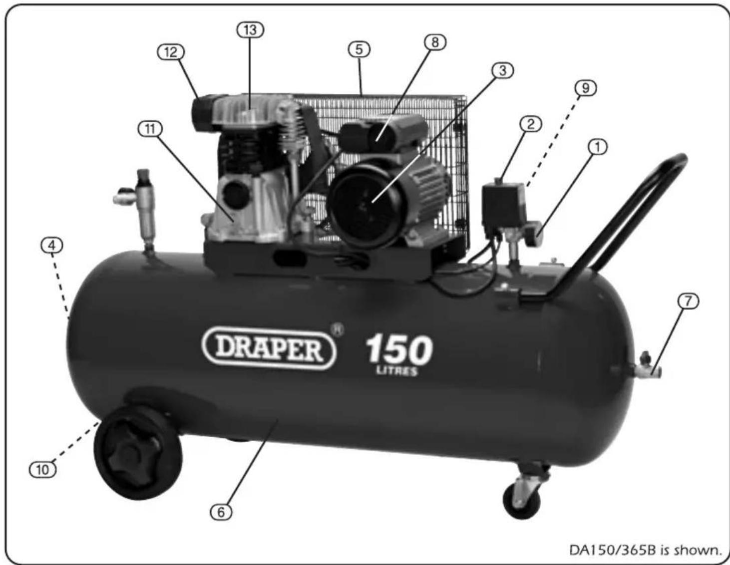
① Tank pressure gauge.
② Pressure switch.
③ Motor.
④ Reservoir inspection plug.
⑤ Pulley guard.
⑥ Reservoir tank.
⑦ Air outlet valve.
⑧ Overload protection reset switch.
⑨ Overload safety relief valve.
⑩ Drain bung.
⑪ Oil level window.
⑫ Air filter.
⑬ Pump unit.
- UNPACKING: After removing the packing material, make sure the product is in perfect condition and that there are no visible damaged parts. If in doubt, do not use the product and contact the dealer from whom it was purchased.
The packaging materials (plastic bags, polystyrene, etc.), must be disposed of in an appropriate refuse collection container. These materials must not be left within the reach of children as they are potential sources of danger.
Upon receipt of the compressor, ensure all components are present and have remained undamaged in transit.
Retain the packing materials and packaging in case future transportation of the compressor is necessary. We recommend that the packaging is kept, at least within the period of the guarantee.
- POSITIONING:
Do not stand the compressor on any surface with a 15^ or greater tilt as this will lead to possible running problems.
Allow a minimum gap of 50cm around the compressor to aid connection and airflow.
In addition to pneumatic air tools, your compressor may be connected to several accessories suitable for blowing, washing and spraying for example.
This unit should only be connected to an in-house air supply rig which incorporates a pressure reducer lubricator and separator.
For technical specifications and detailed instructions, please refer to the instructions provided with the individual accessory.
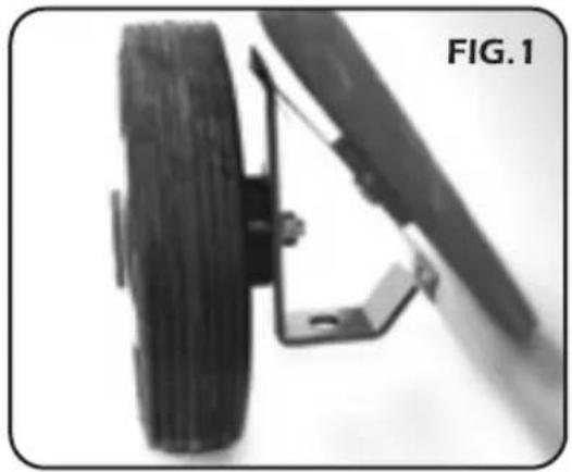
- ASSEMBLING THE WHEELS:
Pass the bolt through the wheel and the metal bracket on the base of the tank and secure in place using washer and nut provided.
ASSEMBLING THE FEET (DA100/365B):
Secure the foot bracket to the bottom of the tank by passing the bolt supplied through the centre hole of the foot bracket and through the tank bracket then secure in place with the washer and nut provided then secure the rubber foot by passing the threaded part through the foot bracket and secure in place with the nut provided.
(DA150/365B):
To assemble the front castor pass the threaded part of the castor through the centre bracket and secure in place using the washer and nut provided.
- AIR TAP ASSEMBLY (Fig.4):
To protect against transit damage, the compressor is delivered with air tap assembly Ⓐ loose in the box. When fixing this in place, ensure a good airtight seal is achieved using a strip of PTFE tape (Draper Stock No.63389) around the thread.
natural_image
Close-up of a mechanical assembly with a tire and lever mechanism (no visible text or symbols)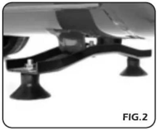
natural_image
Close-up of a mechanical support system with two legs and a central component, labeled 'FIG.2' (no text or symbols on the diagram itself)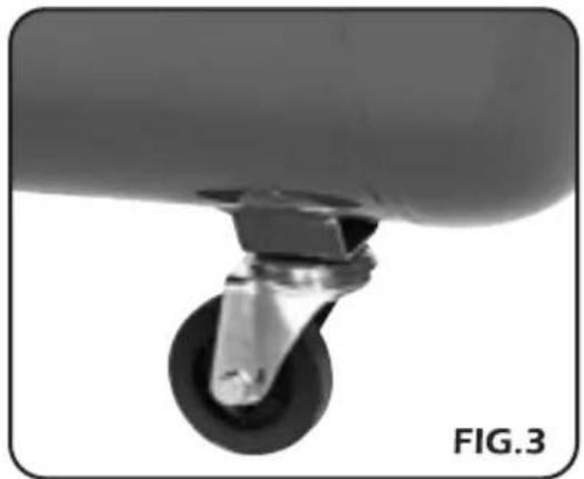
natural_image
Close-up of a mechanical component with a circular head and metallic shaft (no visible text or symbols)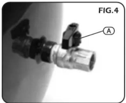
OPERATION AND USE
- POSITIONING:
Mount the compressor on a level surface.
Allow a minimum of a 50cm gap around the compressor to aid connection and airflow.
In addition to pneumatic air tools, your compressor may be connected to several accessories suitable for blowing, washing and spraying.
For technical specifications and detailed instructions, please refer to the instructions provided for the individual accessory.
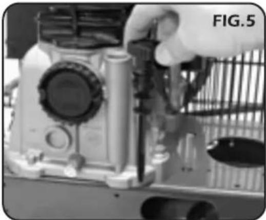
Make sure that the level of oil ranges between the max. and the min. mark on the dipstick (Fig.5). After the first 50 working hours, replace the oil with one of those listed in the table. (see page 11).
When the installation procedure is complete, the compressor is ready for use. Make sure the pressure switch is positioned "OFF" (Fig.6). Switch the power to the "ON" position to start the compressor.
natural_image
Close-up of a hand adjusting a camera lens on a metal frame (no visible text or symbols)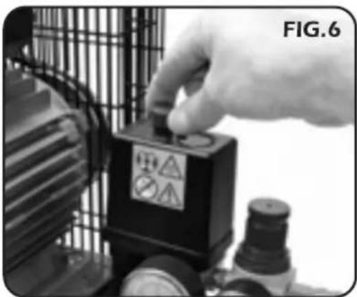
natural_image
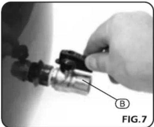
Close-up of a hand adjusting a black electrical component with warning symbols (no readable text or labels)When starting the compressor for the first time, leave it running for about 10 minutes with the air tap Ⓑ completely open (Fig.7).
After this time, close air tap Ⓑ and make sure that pressure in the tank is correct and that the compressor stops automatically when the max. pressure is reached. The pressure is monitored on gauge Ⓒ (Fig.8).
The operation is automatically controlled by the pressure switch which stops the motor when the max. pressure allowed is achieved, and starts it again when the pressure goes below the minimum threshold (about 2 bar less than the max. pressure).
WARNING: Never unplug the compressor or switch off the main switch to stop the compressor. Always position the pressure switch to the off position.
natural_image
Close-up of a hand holding a mechanical component, labeled with 'B' and 'FIG.7' (no readable text or symbols beyond labels)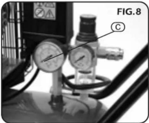
- ADJUSTING THE PRESSURE SWITCH (Fig.9):
NOTE: This is the only operation where it is acceptable to switch the compressor off without using the pressure switch.
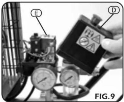
To decrease the pressure switch, run the compressor up to the desired capacity for the pressure switch to be set. At this point, turn the mains power off and do not operate the red button on the pressure switch as this will release the pressure. Disconnect the machine from the power source before loosening screw (D) to remove the black cover. With this removed, the adjustment bolt (E) will be visible. Adjust this anti-clockwise gently until the switch is heard to release the pressure. Release the cover and tighten the screw. The switch will now be set to the new pressure. To increase the pressure switch, remove the switch cover (having disconnected the achine from the power supply) and turn the adjustment bolt clockwise 3 turns and replace the switch cover.
Run the compressor up to the desired capacity for the pressure switch to be set (do not let the compressor run past its maximum pressure). At this point turn the mains power off and disconnect from the supply. Remove the black cover and adjust bolt anti-clockwise gently until the switch is heard to release the pressure. Replace the cover and tighten the screw. The switch will now be set to the new pressure.
- OVERLOAD CUT-OUT (Fig.10)
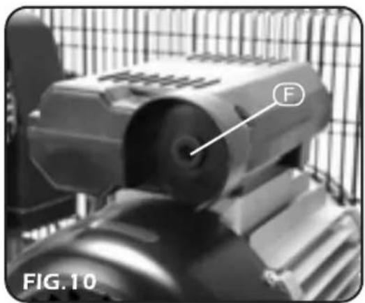
The compressor is equipped with an overload cut-out (F) which operates as a safety device to protect the motor. The device will activate in case of motor overload or overheating due to operation troubles. In this case, the safety device will automatically activate, disconnecting the compressor and avoiding possible motor damages. To restart the compressor, proceed as follows.
- Allow three minutes.
- Position the pressure switch to "0" OFF.
- Manually reset the thermal cut-out.
- Position the pressure switch to "1" ON.
If you restart the compressor and the overload cut-out releases again, turn the main switch to the OFF position, unplug the equipment and contact the Authorised Service Centre.
- NOTE: After reconnection is complete, ensure that the tap is opened again. It is essential to connect an air line filter separator and lubricator to ensure a good, clean air supply is provided for the tool.
( NOTE: If the intended tool for use is a spray gun, use only a filter separator as lubrication will cause contamination of the material being sprayed).
Draper Stock No.51857 - Air filter, Regulator & Lubricator.
Draper Stock No.51858 - Air filter & Regulator.
To ensure an optimum air supply, please refer and carry out the following procedures as recommended.
natural_image
Close-up of a mechanical device with a labeled component 'F' and part number 'FIG.10' (no readable text or symbols beyond labels)- Some of the operations listed in this section will require the compressor to be returned to an authorised service agent.
Before carrying out any service or routine operation to your compressor, ensure the power has been cut off and all pressure has been released from the tank, so as to prevent any sudden unexpected restart. After any maintenance operation, make sure all components have been fitted correctly.
In order to keep your compressor in a good working condition, we recommend you to perform periodical servicing operations. Before performing any maintenance operation, switch off the compressor and ensure all air in the tank is released.
- OPERATIONS TO BE CARRIED OUT AFTER THE FIRST 50 WORKING HOURS:
Check that all screws and bolts are properly tight, paying special care to the head and crank case. Replace the lubricant with one of the recommended oils listed in the table (see page 11).
Never mix different oils together. Do not use non-detergent oils or low quality oils as they have very poor lubricating properties. Do not dispose of the oil in the environment. Always contact your local authority for disposal.
- WEEKLY OPERATIONS:
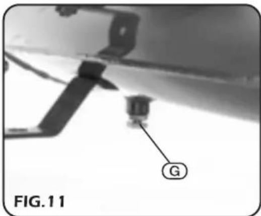
Check the oil level and if necessary top up. Do not exceed the mark corresponding to the max. level. Make sure the oil does not drop below the minimum so as to avoid any damage or seizure. Drain condensation, while the tank is pressurised, by opening the valve ⑧ located under the tank. Open the valve by turning it anti-clockwise (Fig.11) with a container under the valve. Keep the compressor in a position to allow all condensation to flow out completely. The tank must have pressure inside to force out any water present.
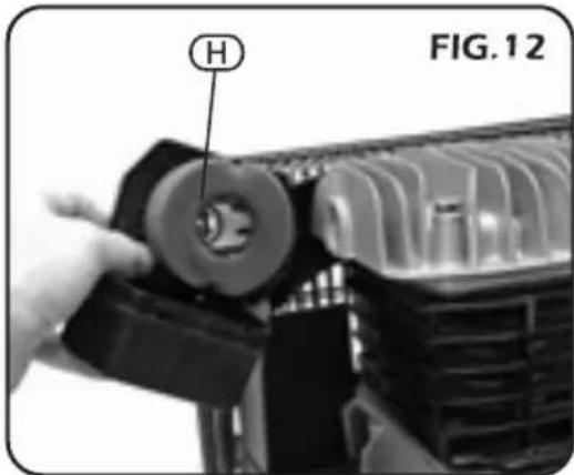
- MONTHLY OPERATIONS (OR MORE FREQUENTLY IF THE COMPRESSOR OPERATES IN VERY DUSTY AREAS) (Fig.12):
Remove the air filter Ⓗ and replace or clean the element. Do not operate the compressor without the air filter fitted, as foreign bodies or dust could seriously damage the inside components.
natural_image
Close-up of a mechanical component with a hand adjusting a circular feature, labeled 'H' and 'FIG.12' (no readable text or symbols beyond label)- OPERATIONS TO BE CARRIED OUT EVERY 6 MONTHS (Fig.13):
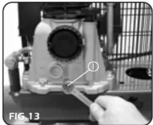
Pull out the oil dipstick and loosen the screw ① to change the oil. Collect the oil into a suitable container.
You should perform this operation when the compressor is hot so as to follow the oil to drain rapidly and completely. Tighten the screw ① in its housing and pour in the new oil up to the max. level and no higher.
It is advisable to clean all the finned parts of your compressor, so as to keep the cooling system efficient and to ensure a long work life to your machine. Check belt tension. Hang a weight of about 3kg at the midpoint of the belt. The belt should flex about 10mm (Fig.13).
If necessary, tension up the belt taking care not to disturb the pulley-to-flywheel alignment. (Fig.14).
- OPERATIONS TO BE CARRIED OUT EVERY 2 YEARS:
Check the non-return valve and if necessary replace the seal. Check intake and delivery valves in valve plates.
- RECOMMENDED OILS:
Recommended oils with ISO 100 viscosity for compressors, in accordance with DIN51506-VDL 100-E Standards and ISO6521:L-DAC Specifications (suitable for room temperature ranging from +6°C and +25°C).
AGIP DICREA100
API CM-8X
BP ENERGOL CS100
CASTROL AIRCOL PD100
ESSO EXX OLUB H150
IP CALATIA OIL ISO 100
MOBIL RARUS 427
FINA EOLAN AC 100
SHELL COREMA OIL H100
TOTAL CORTUSA 100
Use oils with an ISO 46/68 viscosity for a room temperature ranging from 0°C to +5°C.
Use oils with an ISO 150 Viscosity for a room temperature ranging from +26°C to +45°C.
natural_image
Close-up of a mechanical device with a hand holding a tool, labeled 'FIG. 13' (no readable text or symbols on the device itself)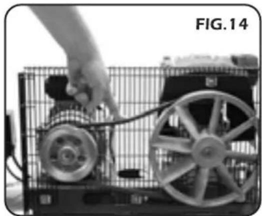
natural_image
Close-up of a hand operating a small wheeled robot with visible wheels and wiring, labeled 'FIG. 14' (no text on the robot or background)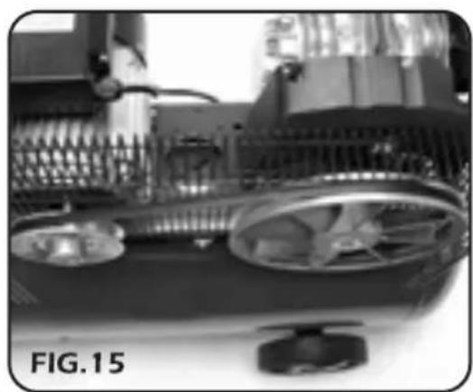
natural_image
Close-up of a mechanical device with gears and a knob, labeled 'FIG.15' (no readable text or symbols on the device itself)USE ONLY ORIGINAL SPARE PARTS, AVAILABLE FROM AUTHORIZED SERVICE AGENTS.
| FAULT | POSSIBLE CAUSE | REMEDY |
| Pressure drop in tank | Air leaks at connections | Allow the compressor to reach max. pressure allowed. Switch it off and brush a soapy water solution onto all air connections. Look carefully for air bubbles flowing out. Tighten those connections where leaks are present. If the problem is still present, contact an authorized service agent |
| The pressure switch valve leaks when the compressor is idle | Non-return valve seal defective | Contact your authorised agent |
| The compressor stopped and does not start | Overload cut-out tripped | See Page 9 |
| The compressor does not stop even though the max. pressure allowed has been reached; the safety valve operates | Incorrect Setting | Contact your authorised agent |
| The compressor does not get to the set pressure and overheats | Compressor head gasket broken or valve faulty | Contact your authorised agent |
| The compressor is noisy with metallic clangs | Bearing or connecting rod seizure | Contact your authorised agent |
| The compressor does not hold regular speed | Belt is slipping | Contact your authorised agent |

DISPOSAL
- At the end of the machine's working life, or when it can no longer be repaired, ensure that it is disposed of according to national regulations.
- Contact your local authority for details of collection schemes in your area.
In all circumstances:
- Do not dispose of power tools with domestic waste.
■ Do not incinerate.
■ Do not abandon in the environment. - Do not dispose of WEEE* as unsorted municipal waste.
* Waste Electrical & Electronic Equipment.

EXPLANATION OF SYMBOLS/PICTOGRAMS

Do not dispose of WEEE* as unsorted municipal waste.
* Waste Electrical & Electronic Equipment.
- DRAPER TOOLS LIMITED,
Hursley Road, Chandler's Ford, Eastleigh, Hampshire. SO53 1YF. U.K. - Helpline: (023) 8049 4344
- Sales Desk: (023) 8049 4333
- Internet: www.draper.co.uk
- E-mail: sales@drapertools.com
- Sales Fax: (023) 8049 4209
- General Enquiries: (023) 8026 6355
- Service/Warranty Repair Agent
For aftersales servicing or warranty repairs, please contact the Draper Tools Helpline for details of an agent in your local area.
YOUR DRAPER STOCKIST
RWDH261110
- DRAPER
- GENERAL INFORMATION
- CONTENTS
- GUARANTEE
- POWER SUPPLY
- CAUTION: Risk of electric shock. Do not open.
- IMPORTANT:
- Keep work area clear
- Consider work area environment
- Guard against electric shock
- Keep other persons away
- Store idle tools
- Do not force the tool
- Use the right tool
- Dress properly
- Use protective equipment
- Connect dust extraction equipment
- Do not abuse the cord
- Secure work
- Do not overreach
- Maintain tools with care
- Disconnect tools
- Remove adjusting keys and wrenches
- Avoid unintentional starting
- Use outdoor extension leads
- Stay alert
- Check damaged parts
- Warning
- Have your tool repaired by a qualified person
- - POSITIONING:
- - ASSEMBLING THE WHEELS:
- ASSEMBLING THE FEET (DA100/365B):
- (DA150/365B):
- - AIR TAP ASSEMBLY (Fig.4):
- OPERATION AND USE
- - OPERATIONS TO BE CARRIED OUT EVERY 6 MONTHS (Fig.13):
- - OPERATIONS TO BE CARRIED OUT EVERY 2 YEARS:
- - RECOMMENDED OILS:
- DISPOSAL
- EXPLANATION OF SYMBOLS/PICTOGRAMS
Brand : Draper
Model : 230V 150L
Category : Compressor