
8340APM - Loudspeaker GENELEC - Free user manual and instructions
Find the device manual for free 8340APM GENELEC in PDF.


| Product Type | Active Studio Monitor Speaker |
| Model | 8340APM |
| Brand | Genelec |
| Woofer | 6.5 inches (165 mm) cone |
| Tweeter | 3/4 inches (19 mm) metal dome |
| Amplifier Power | 150 W (LF 90 W + HF 60 W) |
| Frequency Response | 38 Hz – 25 kHz (-6 dB) |
| Maximum SPL | 104 dB (short term) |
| Crossover Frequency | 2.8 kHz |
| Input Connectors | 1 XLR analog, 1 RCA analog |
| Input Impedance | 10 kΩ balanced, 50 kΩ unbalanced |
| Dimensions (HxWxD) | 347 x 237 x 237 mm (13 5/8 x 9 5/16 x 9 5/16 in) |
| Weight | 6.4 kg (14.1 lb) |
| Power Consumption | Idle 5 W, Standby 0.5 W |
| Standby Mode | Automatic ISS (Intelligent Signal Sensing) after ~60 minutes |
| Room Response Controls | Bass tilt, bass roll-off, treble tilt |
| Housing Material | Die-cast aluminum |
| Included Accessories | Power cord, user manual, rubber pads |
| Safety | Use with grounded outlet; ensure ventilation |
| Maintenance | Clean with soft dry cloth; avoid liquids |
| Repair | Contact authorized service; no user-serviceable parts |
| Warranty | 2 years (subject to conditions) |
| Country of Origin | Finland |
Frequently Asked Questions - 8340APM GENELEC
User questions about 8340APM GENELEC
0 question about this device. Answer the ones you know or ask your own.
Ask a new question about this device
Download the instructions for your Loudspeaker in PDF format for free! Find your manual 8340APM - GENELEC and take your electronic device back in hand. On this page are published all the documents necessary for the use of your device. 8340APM by GENELEC.
USER MANUAL 8340APM GENELEC
natural_image
Two black studio speakers with sound waves and a 'GENELEC' logo, no visible text or symbols on the devices themselves.Introduction
Congratulations and a thank you for the purchase of this Genelec Smart Active Monitor (SAM) system. This manual addresses the stand-alone setup and use of the 8340A and 8350A SAM monitors. These monitors can also be set up and used with the Genelec Loudspeaker Manager GLM ^™ and the proprietary Genelec monitor control network and software, offering much more versatile acoustic settings and features. Use with the GLM ^™ is described in the GLM ^™ System Operating Manual.
All Genelec SAM systems are designed to integrate easily into all professional environments, supporting both standard analog line level audio and AES/EBU formatted digital audio signals.
The 8340A and 8350A are suitable for professional monitoring tasks demanding high precision and reliability of monitoring. The Minimum Diffraction Enclosure ^™ (MDE ^™ ) and advanced Directivity Control Waveguide ^™ (DCW ^™ ) technologies provide excellent frequency balance even in difficult acoustic environments.
Each monitor is supplied with a mains cable, one 5 m GLM network cable and an operating manual.
Energy saving Intelligent Signal Sensing (ISS ^™ ) can be turned on to put the monitor automatically into a deep sleep state where the product consumes less than one Watt of power. Upon sensing an input signal the monitor automatically wakes up to full operation. The wait until entering the ISS power save can be configured using the GLM software. When the ISS is active you can have your monitoring system ready for action at all times.
System setup using GLM™ Control Network
Although the 8340A and 8350A can be used without the GLM ^™ software and control network, they only reach their full potential when set up and calibrated using the GLM ^™ software. Genelec Loudspeaker Manager GLM ^™ and the proprietary Genelec monitor control network and software offer automated acoustic equalization and alignment for any reproduction system from simple stereo to very complex 3D immersive audio setups including also one or more subwoofers. GLM setup is fast and accurate. The settings can be controlled with a computer or be permanently stored in the monitors to make the setup available at all times even when a computer is not in use. Genelec recommends setting up SAM monitoring systems using GLM. You can find a detailed description of the setup and the use of GLM ^™ in the GLM ^™ System Operating Manual.
The setup is fast and consists of the following steps:
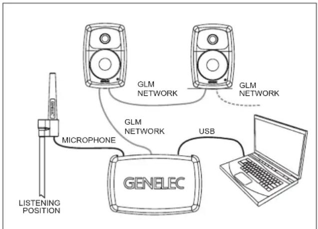
- Connect a CAT5 (RJ45) cable between each monitor (and subwoofer) and finally to the control network input of the GLM Adapter device (see Figure 1).
- Connect the GLM Adapter device to computer USB connector.
- Using a microphone stand, place the Genelec measurement microphone at the listening location with the microphone pointing upwards and the microphone top at the height of the engineer's ear. The microphone is a part of the GLM User Kit.
flowchart
graph TD
    A["LISTENING POSITION"] --> B["MICROPHONE"]
    B --> C["GENELEC"]
    C --> D["USB"]
    D --> E["Laptop"]
    F["GLM NETWORK"] --> C
    G["GLM NETWORK"] --> C
    H["GLM NETWORK"] --> C
Figure 1. GLM control network cabling
- Connect the microphone cable to the microphone input in the GLM Adapter device.
- Download the GLM software at the Genelec web site (www.genelec.com).
• Install the GLM software and follow the instructions in the software to measure and set up your monitors. - If you plan to not use a computer for controlling the monitors, use the GLM software to write the setting into the monitors (use menu item "Store | Store the Current Group Settings...").
While the GLM network is disconnected the settings stored using the Genelec Loudspeaker Manager software can be selected in use by setting the STORED switch ON.
Setup without using the GLM
When GLM is not available, you can use the settings on the monitor for system setup. These settings are limited but provide the basic acoustical calibrations and input selection. To use this method, set the STORED switch OFF.
Connect the MAINS INPUT to the mains supply. These products support any mains voltage globally (100-240 VAC, 50-60 Hz) so they can be plugged in anywhere. If the mains power is provided with a generator, inverter or certain lower-quality UPS devices, we recommend filtering of the mains power voltage harmonics and taking care that the voltage supply is stable.
The ANALOG IN connector is used for analog audio signals. The maximum input level is +25 dBu. These monitors produce 100 dB SPL sound level at 1 meter in free space for an analogue input signal of -6 dBu.
The DIGITAL IN AES/EBU female XLR connector is for AES/EBU formatted digital audio input signals. This input is selected automatically when a valid digital audio signal is present. Analog input is selected when the AES/EBU signal input is disconnected. The AES/EBU input supports two channels in a single cable). When the digital source device controls the digital output level, it may be advantageous to lower the level on the monitor's controls, which will enable the use of a higher digital signal level with more digital resolution. With digital inputs the audio is referenced to 0 dBFS (dB relative to the digital full scale, the largest level that can be represented in the AES/EBU signal).
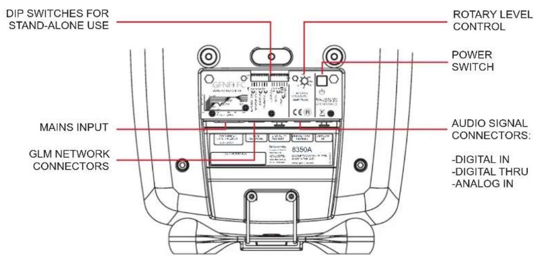
Figure 2. Connectors and controls on the back panel of a 8350A. 8340A shares the same layout.
These monitors produce 100 dB SPL sound level at 1 meter in free space for a digital input signal of -30 dBFS. The DIGITAL OUT male XLR carries an unaltered copy of the digital signal fed into the digital in connector. This enables daisy-chaining up to four monitors.
The CONTROL NETWORK RJ-45 connectors are used with Genelec Loudspeaker Manager™ (GLM™) network. These connectors are not Ethernet LAN compatible. Do not connect to Ethernet LAN.
Stand-Alone Control Functions
Bass Roll-Off Control
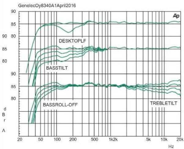
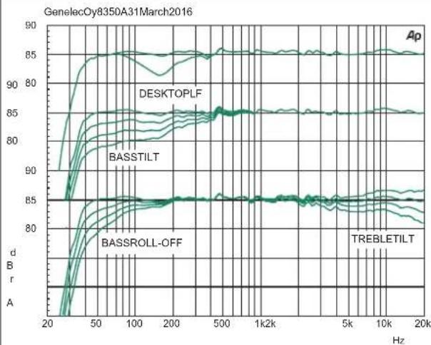
Bass Roll-Off control attenuates the monitor's output near the cut-off frequency. Attenuation levels of -2 dB, -4 dB or -6 dB (both switches ON) can be selected.
Desktop 160 Hz
The desktop low frequency control (switch 5) attenuates the bass frequencies around 160 Hz by 4 dB. This feature is designed to compensate for the boost often occurring at this frequency range when the monitor is placed upon a meter bridge, table or similar reflective surface.
Bass Tilt Control
The Bass Tilt control switches (switches 3 and 4) offer three attenuation levels for the bass response below 800 Hz, usually necessary when the monitors are placed near room boundaries. The attenuation levels are -2 dB, -4 dB and -6 dB.
Treble Tilt Control
Treble Tilt control allows adjusting the treble response above 5 kHz by +2 dB, -2 dB or -4 dB, which can be used for correcting an excessively bright or dull sounding system or to compensate for high frequency level loss if the monitor is placed behind a screen.
LED Disable
This switch shuts off the front panel LED light.
| Monitor Mounting Position | Treble Tilt | Bass Tilt | Bass Roll-Off | Desktop |
| Flat anechoic response | None | None | None | None |
| Free standing in a damped room | None | -2 dB | None | None |
| Free standing in a reverberant room | None | -4 dB | None | None |
| Near field on a reflective surface | None | -2 dB | None | -4 dB |
| In a corner | None | -4 dB | -4 dB | None |
Table 1. Suggested Tone Control settings for some typical monitor placement positions.
ISS
This switch activates or deactivates the ISS automatic power saving function. The default time for ISS activation is 60 minutes, but can be adjusted in GLM.
Digital
The Digital switch selects the digital audio channels on the AES/EBU. Turning both switches on reproduces the sum of the A and B channels. A 6 dB of attenuation is applied to avoid overloading the monitor. If the AES/EBU cable is operated in dual-wire mode, the monitor detects this automatically and the channel selection switches have no effect.
Level
The Level switches scale down the monitor output level in 10 dB steps. The effects of these switches add up and combine with the effect of the rotary level adjustment control. The combined total setting range is 42 dB.
Stored
Stored switch selects the use of the controls on the monitor's back panel or the settings stored inside the monitor memory using the GLM system calibration software. Setting the Stored switch to OFF position selects the settings defined by the monitor's own controls. Setting the Stored switch to ON position selects the use of internally stored GLM settings. Using the
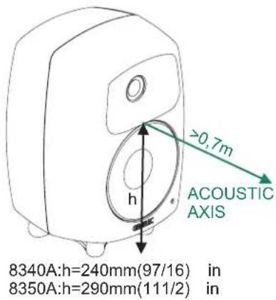
Figure 3. The location of the acoustic axis is on the centerline of the monitor at the given height "h".
flowchart
graph TD
    A["Central Device"] --> B["Device 1"]
    A --> C["Device 2"]
    A --> D["Device 3"]
    A --> E["Device 4"]
    A --> F["Device 5"]
    A --> G["Device 6"]
    A --> H["Device 7"]
    A --> I["Device 8"]
    A --> J["Device 9"]
    A --> K["Device 10"]
    A --> L["Device 11"]
    A --> M["Device 12"]
    A --> N["Device 13"]
    A --> O["Device 14"]
    A --> P["Device 15"]
    A --> Q["Device 16"]
    A --> R["Device 17"]
    A --> S["Device 18"]
    A --> T["Device 19"]
    A --> U["Device 20"]
    A --> V["Device 21"]
    A --> W["Device 22"]
    A --> X["Device 23"]
    A --> Y["Device 24"]
    A --> Z["Device 25"]
Figure 4. Symmetrical layout and keeping the acoustic axis clear from obstructions minimizes reflection surfaces and maintains accurate localisation because reflections are symmetrical.

Figure 5. Recommended distances from a single wall to the front baffle of free-standing monitors. Correct (green) and not recommended (red).
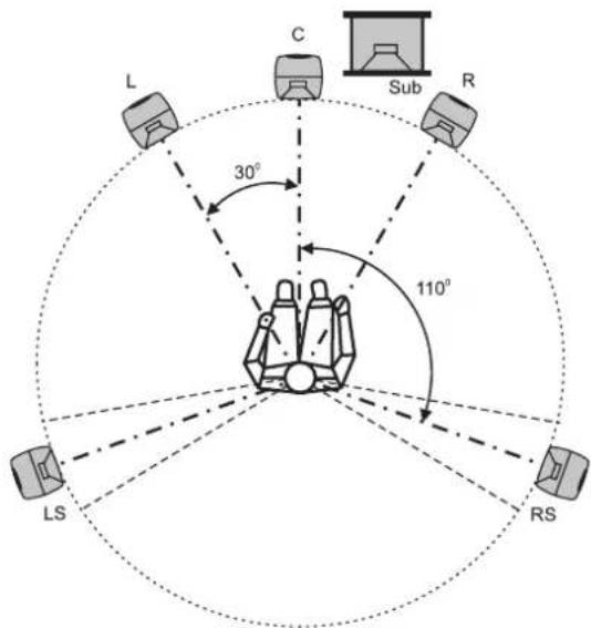
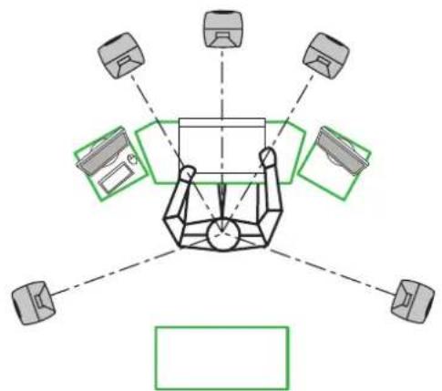
Figure 6. Recommended monitor positioning for 5.1 multi-channel audio reproduction
Stored option overrides all adjustments done with the monitor's own controls.
Operating Environment
These monitors are designed for indoor use only. The permissible ambient temperature is 15-35 degrees Celsius (50-95°F) and relative humidity 20% to 80% (non-condensing). When the product has been stored or transported in cool environment and is taken into a warm room, wait 0.5-1 hours before opening any packing to prevent condensation of humidity before connecting to mains power. Sufficient cooling must be ensured. The minimum clearance is 50 mm (2 in) behind, above and on both sides of the monitor. The space must be ventilated sufficiently to dissipate the heat.
Mounting and Placing Monitors
Mounting Options
The vibration insulating Isolation Positioner/Decoupler™ (IsoPod™) table stand allows tilting of the monitor for correct alignment of the acoustic axis. The stand can be attached to three points on the enclosure, allowing vertical and two horizontal positions. Aim the monitor so that its acoustic axis point towards the listening position (see Figure 3). Vertical orientation is preferable, as this eliminates acoustical cancellation problems around the crossover frequency. Place the monitors symmetrically at equal distances from the listening position. If possible, place the listening position on the left-right centerline of the room (see Figure 4). When a monitor far away (1 to 2.2 m, 3-7 ft) from the acoustically hard wall behind the monitor, an acoustic reflection from the wall may cause cancellation of low frequencies and reduce bass output.
| Colour Indication | |
| Solid greed | Normal state, normal operation |
| Blinking green | GLM is adjusting the monitor |
| Green blink every 10 sec. | Monitor is an ISS power saving sleep state |
| Red blink | Power amplifier overload protection is active (audio is modified because of protection) |
| Solid red | Monitor is muted |
| Yellow | Monitor is not in the active (playing) group |
| Yellow blinking | Overheat protection is active (audio is modified because of protection) |
Table 2. Monitor front panel light indications summary
Acoustic reflections from objects like desks, cabinets, computer monitors etc. can cause unwanted colouration and blurring of the sound image. Minimise these by placing the monitors away from acoustically reflective surfaces. Putting the monitors on stands behind and above a mixing console usually improves the response over placing monitors on a meter bridge. Symmetrical positioning of the sound reflecting objects maintains a balanced soundstage (see Figure 4).
A wide variety of ceiling and wall mounts are available through your Genelec dealer. Genelec 8340A and 8350A can be fitted with König & Meyer monitor mounts using two M6 x 10 mm threaded holes on the enclosure back. There is an M10 x 10 mm threaded hole in the base of the monitor. Do not use this thread for mounting the monitor on a microphone stand. Monitor stands typically have an incompatible 3/8" UNC thread. A wide selection of accessories is available for Genelec monitors. Consult the Genelec Accessories Catalogue at www.genelec.com or your local distributor/dealer for information.
Front Panel Light
Normally, the light on the front panel is green, indicating normal operational mode. Red and yellow colours are used to indicate special situations. See Table 2 above.
Use with Subwoofers
Genelec recommends using the 7300 series subwoofers. For more detailed system configuration and matching products, please consult the on-line Genelec Product Selection Tool at www.genelec.com.
Maintenance
There are no user serviceable parts inside the monitor. Maintenance or repair must only be done by a Genelec certified service.
Safety Considerations
Although the 8340A and 8350A have been designed in accordance with international safety standards, to ensure safe operation and to maintain the monitor under safe operating conditions, the following warnings and precautions must be observed:
- Servicing and adjustment must only be performed by a certified Genelec service. The monitor enclosure must not be opened.
- Do not use this product with an unearthed mains cable or a mains connection without the protective earth contact as this may lead to personal injury.
- To prevent fire or electric shock, do not expose the unit to water or moisture.
- Do not place any objects filled with liquid, such as vases on the monitor or near it.
- Note that the amplifier is not completely disconnected from the AC mains service unless the mains power cord is removed from the amplifier or the mains outlet.
- Free flow of air behind the monitor is necessary to maintain sufficient cooling.
• Do not obstruct airflow around the monitors.
WARNING!
These monitors are capable of producing sound pressure levels in excess of 85 dB, which may cause permanent hearing damage.
Guarantee
Genelec 8340A and 8350A are guaranteed for two years against manufacturing faults or defects altering performance. Refer to the reseller for full sales and guarantee terms.
Compliance to FCC Rules
Note: This equipment has been tested and found to comply with the limits for a Class B digital device, pursuant to part 15 of the FCC Rules. These limits are designed to provide reasonable protection against harmful interference in a residential installation. This equipment generates, uses and can radiate radio frequency energy and, if not installed and used in accordance with the instructions, may cause harmful interference to radio communications. However, there is no guarantee that interference will not occur in a particular installation. If this equipment does cause harmful interference to radio or television reception, which can be determined by turning the equipment off and on, the user is encouraged to try to correct the interference by one or more of the following measures:
• Reorient or relocate the receiving antenna.
- Increase the separation between the equipment and receiver.
- Connect the equipment into an outlet on a circuit different from that to which the receiver is connected.
- Consult the dealer or an experienced radio/TV technician for help
- Modifications not expressly approved by the manufacturer could void the user's authority to operate the equipment under FCC rules.
line
| Frequency (Hz) | d B (dB) | | -------------- | -------- | | 20 | ~85 | | 50 | ~85 | | 100 | ~85 | | 200 | ~85 | | 500 | ~85 | | 1k | ~85 | | 5k | ~85 | | 10k | ~85 | | 20k | ~85 |Figure 11. The curves above show the effect of the "Bass Tilt", "Treble Tilt", "Desktop Low Frequency" and "Bass Roll-Off" controls on the free field response of the 8340A.
line
| Frequency (Hz) | Ap | DESKTOPLF | BASSTILT | BASSROLL-OFF | TREBLETILT | | -------------- | ----- | --------- | -------- | ------------ | ---------- | | 20 | 85.0 | 85.0 | 85.0 | 85.0 | 85.0 | | 50 | 85.0 | 85.0 | 85.0 | 85.0 | 85.0 | | 100 | 85.0 | 85.0 | 85.0 | 85.0 | 85.0 | | 200 | 85.0 | 85.0 | 85.0 | 85.0 | 85.0 | | 500 | 85.0 | 85.0 | 85.0 | 85.0 | 85.0 | | 1k | 85.0 | 85.0 | 85.0 | 85.0 | 85.0 | | 5k | 85.0 | 85.0 | 85.0 | 85.0 | 85.0 | | 10k | 85.0 | 85.0 | 85.0 | 85.0 | 85.0 | | 20k | 85.0 | 85.0 | 85.0 | 85.0 | 85.0 |Figure 12. The curves above show the effect of the "Bass Tilt", "Treble Tilt", "Desktop Low Frequency" and "Bass Roll-Off" controls on the free field response of the 8350A.
line
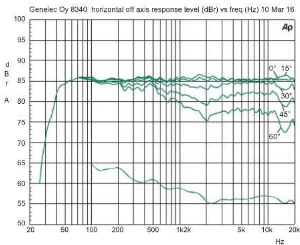
| Frequency (Hz) | 0° | 15° | 30° | 45° | 60° | | -------------- | ----- | ----- | ----- | ----- | ----- | | 20 | 60.0 | 60.0 | 60.0 | 60.0 | 60.0 | | 50 | 85.0 | 85.0 | 85.0 | 85.0 | 85.0 | | 100 | 85.0 | 85.0 | 85.0 | 85.0 | 85.0 | | 200 | 85.0 | 85.0 | 85.0 | 85.0 | 85.0 | | 500 | 85.0 | 85.0 | 85.0 | 85.0 | 85.0 | | 1k | 85.0 | 85.0 | 85.0 | 85.0 | 85.0 | | 5k | 85.0 | 85.0 | 85.0 | 85.0 | 85.0 | | 10k | 85.0 | 85.0 | 85.0 | 85.0 | 85.0 | | 20k | 85.0 | 85.0 | 85.0 | 85.0 | 85.0 |Figure 13. The upper curve group shows the horizontal directivity characteristics of the 8340A measured at 1 m. The lower curve shows the system's power response.
line
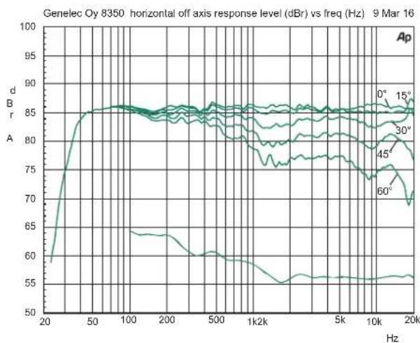
| Frequency (Hz) | 0° | 15° | 30° | 45° | 60° | | -------------- | ----- | ----- | ----- | ----- | ----- | | 20 | 60.0 | 60.0 | 60.0 | 60.0 | 60.0 | | 50 | 85.0 | 85.0 | 85.0 | 85.0 | 85.0 | | 100 | 85.0 | 85.0 | 85.0 | 85.0 | 85.0 | | 200 | 85.0 | 85.0 | 85.0 | 85.0 | 85.0 | | 500 | 85.0 | 85.0 | 85.0 | 85.0 | 85.0 | | 1k2k | 85.0 | 85.0 | 85.0 | 85.0 | 85.0 | | 5k | 85.0 | 85.0 | 85.0 | 85.0 | 85.0 | | 10k | 85.0 | 85.0 | 85.0 | 85.0 | 85.0 | | 20k | 85.0 | 85.0 | 85.0 | 85.0 | 85.0 |Figure 14. The upper curve group shows the horizontal directivity characteristics of the 8350A measured at 1 m. The lower curve shows the system's power response.
line
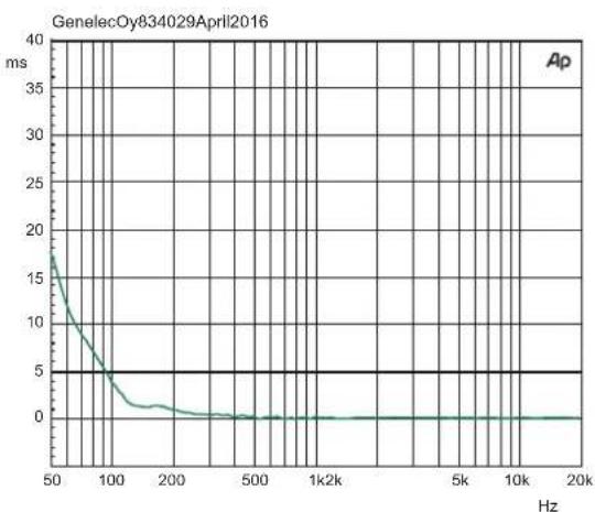
| Hz | ms | | ---- | --- | | 50 | 17 | | 100 | 5 | | 200 | 1 | | 500 | 0.5 | | 1k | 0.2 | | 5k | 0.1 | | 10k | 0.05| | 20k | 0.02|Figure 14. The curve above shows the delay variation of the 8340A as a function of frequency.
line
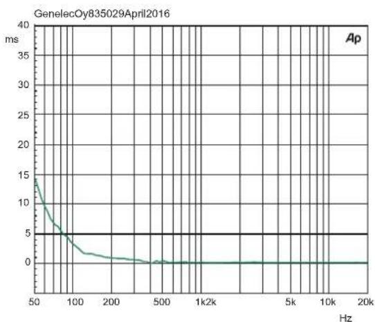
| Hz | ms | | ---- | --- | | 50 | 15 | | 100 | 5 | | 200 | 1 | | 500 | 0 | | 1k2k | 0 | | 5k | 0 | | 10k | 0 | | 20k | 0 |Figure 15. The curve above shows the delay variation of the 8350A as a function of frequency.
heatmap
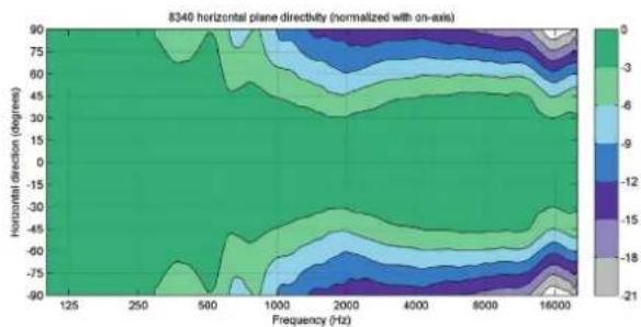
8340 horizontal plane directivity (normalized with on-axis) | Frequency (Hz) | -90 | -75 | -60 | -45 | -30 | -15 | 0 | 15 | 30 | 45 | 60 | 75 | |---|---|---|---|---|---|---|---|---|---|---|---|---| | 125 | 0 | 0 | 0 | 0 | 0 | 0 | 0 | 0 | 0 | 0 | 0 | 0 | | 250 | 0 | 0 | 0 | 0 | 0 | 0 | 0 | 0 | 0 | 0 | 0 | 0 | | 500 | 0 | 0 | 0 | 0 | 0 | 0 | 0 | 0 | 0 | 0 | 0 | 0 | | 1000 | 0 | 0 | 0 | 0 | 0 | 0 | 0 | 0 | 0 | 0 | 0 | 0 | | 2000 | 0 | 0 | 0 | 0 | 0 | 0 | 0 | 0 | 0 | 0 | 0 | 0 | | 4000 | 0 | 0 | 0 | 0 | 0 | 0 | 0 | 0 | 0 | 0 | 0 | 0 | | 8000 | 0 | 0 | 0 | 0 | 0 | 0 | 0 | 0 | 0 | 0 | 0 | 0 | | 16000 | 0 | 0 | 0 | 0 | 0 | 0 | 0 | 0 | 0 | 0 | 0 | 0 | The chart displays a color-coded contour plot representing the magnitude of the measured variable at each frequency point. The x-axis represents frequency in Hz, and the y-axis represents horizontal direction in degrees. The color scale ranges from -21 (light gray) to +9 (dark green), indicating the value of the measured variable at that frequency. No explicit numerical values are provided for the plotted data points.Figure 16. The curves above show the horizontal directivity characteristics of the 8340A.
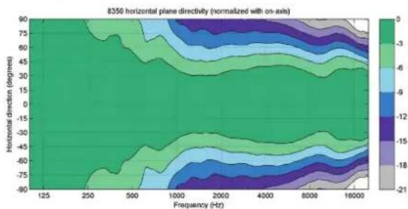
Figure 17. The curves above show the horizontal directivity characteristics of the 8350A.
heatmap
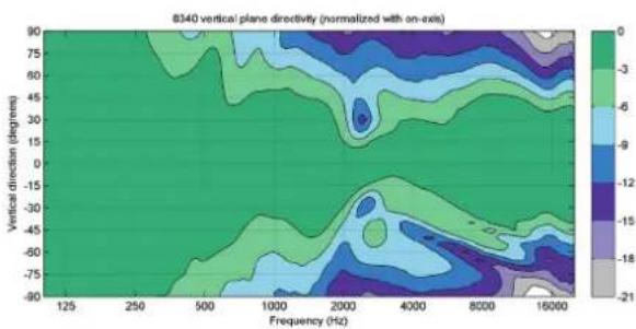
| Frequency (Hz) | 125 | 250 | 500 | 1000 | 2000 | 4000 | 8000 | 16000 | | -------------- | ----- | ----- | ----- | ----- | ----- | ----- | ----- | ----- | | Vertical direction (degrees) | -90 | -75 | -50 | -25 | 0 | 25 | 50 | 75 | | Vertical direction (degrees) | -75 | -50 | -25 | 0 | 25 | 50 | 75 | 160 | | Vertical direction (degrees) | -50 | -25 | 0 | 25 | 50 | 75 | 160 | 21 | | Vertical direction (degrees) | -25 | 0 | 25 | 50 | 75 | 160 | 21 | 21 | | Vertical direction (degrees) | 0 | 25 | 50 | 75 | 160 | 21 | 21 | 21 | | Vertical direction (degrees) | 25 | 50 | 75 | 160 | 21 | 21 | 21 | 21 | | Vertical direction (degrees) | 50 | 75 | 160 | 21 | 21 | 21 | 21 | 21 | | Vertical direction (degrees) | 75 | 160 | 21 | 21 | 21 | 21 | 21 | 21 | | Vertical direction (degrees) | 160 | 21 | 21 | 21 | 21 | 21 | 21 | 21 | | Vertical direction (degrees) | 21 | 21 | 21 | 21 | 21 | 21 | 21 | 21 | | Vertical direction (degrees) | 21.5 | 21.5 | 21.5 | 21.5 | 21.5 | 21.5 | 21.5 | 21.5 | | Vertical direction (degrees) | 26.5 | 26.5 | 26.5 | 26.5 | 26.5 | 26.5 | 26.5 | 26.5 | | Vertical direction (degrees) | 36.5 | 36.5 | 36.5 | 36.5 | 36.5 | 36.5 | 36.5 | 36.5 | | Vertical direction (degrees) | 49.5 | 49.5 | 49.5 | 49.5 | 49.5 | 49.5 | 49.5 | 49.5 | | Vertical direction (degrees) | 68.95 | 68.95 | 68.95 | 68.95 | 68.95 | 68.95 | 68.95 | 68.95 | | Vertical direction (degrees) | -78.99| -78.99| -78.99| -78.99| -78.99| -78.99| -78.99| -78.99| | Vertical direction (degrees) | -33.33| -33.33| -33.33| -33.33| -33.33| -33.33| -33.33| -33.33| | Vertical direction (degrees) | -44.44| -44.44| -44.44| -44.44| -44.44| -44.44| -44.44| -44.44| | Vertical direction (degrees) | -77.77| -77.77| -77.77| -77.77| -77.77| -77.77| -77.77| -77.77| | Vertical direction (degrees) | -88.89| -88.89| -88.89| -88.89| -88.89| -88.89| -88.89| -88.89| | Vertical direction (degrees) | -99.99| -99.99| -99.99| -99.99| -99.99| -99.99| -99.99| -99.99| The chart displays a contour plot of directivity values for vertical orientation relative to the frequency axis (Hz). The color scale ranges from gray (-21) to white (+3). The legend is embedded in the plot area.Figure 18. The curves above show the vertical directivity characteristics of the 8340A.
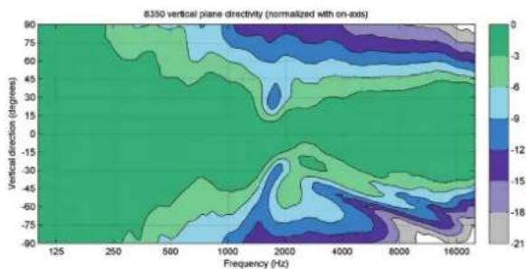
Figure 19. The curves above show the horizontal directivity characteristics of the 8350A.
SYSTEM SPECIFICATIONS
| 8340A 8350A | ||
| Lower cut-off frequency, -6 dB < 38 Hz < 33 Hz | ||
| Upper cut-off frequency, -6 dB >22 kHz >22 kHz | ||
| Accuracy of frequency response, ± 1.5 dB 45 Hz - 20 kHz 38 Hz - 20 kHz | ||
| Maximum short term sine wave acoustic output on axis in half space, averaged from 100 Hz to 3 kHz at 1 m | ≥ 110 dB SPL ≥ 112 dB SPL | |
| Maximum long term RMS acoustic output in the same conditions with IEC weighted noise (limited by driver protection circuit) at 1 m | 100 dB SPL 103 dB SPL | |
| Maximum peak acoustic output per pair in a listening room with music material at 1 m | ≥ 118 dB | ≥ 121 dB |
| Self generated noise level in free space at 1 m on axis (A-weighted) ≤ 5 dB | ||
| Harmonic distortion at 90 dB SPL at 1 m on axisFreq: 50...100 Hz>100 Hz | < 2 %< 0.5 % | |
| DriversBassTrebleAll drivers are magnetically shielded | 165 mm ( 6^1/_2 in) cone 205 mm (8 in) cone19 mm ( 3/_4 in) metal dome 25 mm (1 in) metal dome | |
| Weight 8.4 kg (18.5 lb) 12.8 kg (28.2 lb) | ||
| DimensionsHeightWidthDepthHeight with Iso-PodTM | 350 mm ( 13^13/_16 in) 433 mm ( 17^1/_16 in)237 mm ( 9^3/_8 in) 286 mm ( 11^1/_4 in)223 mm ( 8^13/_16 in) 278 mm ( 10^15/_16 in)365 mm ( 14^3/_4 in) 452 mm ( 17^13/_16 in) | |
AMPLIFIER SECTION
| 8340A 8350A | ||
| Bass amplifier short term output powerTreble amplifier short term output power(Long term output power is limited by driver protection circuitry) | 150 W150 W | 150 W200 W |
| Amplifier system THD at nominal output <0.01% | ||
| System Signal to Noise ratio, A-weightedBassTreble | >109 dB>110 dB | >109 dB>112 dB |
| Mains voltage 100-240 VAC 50/60 Hz | ||
| Power consumptionISS activeIdleFull output (short term) | <1 W12 W180 W | <1 W12 W230 W |
SIGNAL PROCESSING SECTION
| 8340A 8350A | ||
| Analog signal input connector XLR female, balanced 10 kOhm | pin 1 gndpin 2 non-inverting,pin 3 inverting+25.0 dBu-6 dBuAdjustable from +6 to -6 dBu | |
| Maximum analog input signal | ||
| Analog input sensitivity (100 dB SPL at 1 m) | ||
| Analog input gain selection, rotary control | ||
| Digital signal input connector XLR female 110 Ohm | AES/EBU Single Wire | |
| Digital signal output / Thru connector XLR male 110 Ohm | AES/EBU Single Wire | |
| Digital audio inputWord lengthSample rateDigital input sensitivity (100 dB SPL at 1 m)Digital input gain sensitivity, rotary control | 16 - 24 bits32 - 192 kHz-30 dBFSAdjustable from +6 to -6 dBu | |
| Control networkTypeConnection | Proprietary GLM ^TM network2 RJ45, CAT5 cables | |
| Crossover frequency 2.6 kHz 1.8 kHz | ||
| GLM ^TM software frequency response adjustment*Parametric notch filtersShelving filters | 162 LF and 2 HF | |
| System room response calibration Genelec GLM AutoCal ^TM AutoCal | ^TM , GLM ^TM manual,Stand-alone* | |
^a The notch and shelving filters adjustments, AutoCal ^™ and GLM ^™ manual system calibration features are part of the Genelec Loudspeaker Manager (GLM ^™ ) software
Genelec Document D0133R001 Copyright Genelec Oy 5.2016. All data subject to change without prior notice.
www.genelec.com
GENELEC®
International enquiries: Genelec, Ovlittle 5 FIN-74100, lisalmi, Finland Phone +358 17 83881 Fax +358 17 812 267 Email genelec@genelec.com
In the U.S. please contact: Genelec, Inc., 7 Tech Circle Natick, MA 01760, USA Phone +1 508 652 0900 Fax +1 508 652 0909 Email genelec.usa@genelec.com
In Sweden please contact: Genelec Sverige Ellipsvägen 10B P.O. Box 5521, S-141 05 Huddinge Phone +46 8 449 5220 Fax +46 8 708 7071 Email info@genelec.com
In China please contact: Beijing Genelec Audio Co.Ltd Room 101, 1st floor Building 71 B33 Universal Business Park No. 10 Jluxianqiao Road Chaoyang District Beijing, China Phone +86 (10) 5623 2014 Post code: 100015 Email genelec.china@genelec.com
- Introduction
- System setup using GLM™ Control Network
- Setup without using the GLM
- Stand-Alone Control Functions
- Bass Roll-Off Control
- Desktop 160 Hz
- Bass Tilt Control
- Treble Tilt Control
- LED Disable
- ISS
- Digital
- Level
- Stored
- Operating Environment
- Mounting and Placing Monitors
- Mounting Options
- Front Panel Light
- Use with Subwoofers
- Maintenance
- Safety Considerations
- WARNING!
- Guarantee
- Compliance to FCC Rules
Brand : GENELEC
Model : 8340APM
Category : Loudspeaker