
840772 - Grinder KAWASAKI - Free user manual and instructions
Find the device manual for free 840772 KAWASAKI in PDF.


| Type of Product | Air Grinder |
| Brand | Kawasaki |
| Model | 840772 |
| No Load Speed | 17,000 RPM |
| Air Inlet Size | 1/4 in. NPT (6.35 mm) |
| Air Consumption | 4-9 CFM |
| Recommended Air Pressure | 90 PSI |
| Suggested Air Hose Size | 3/8 in. (9.52 mm) |
| Collet Sizes | 1/4 in. and 6 mm |
| Power Source | Compressed Air |
| Lubrication | Marvel Mystery Oil recommended |
| Safety Features | Safety lock, trigger lever |
| Intended Use | Consumer use only |
| Maximum Operating Pressure | 90 PSI |
| Weight | Approx. 1.5 lbs (0.68 kg) |
| Length | Approx. 6.5 in (16.5 cm) |
| Maintenance | Daily lubrication; blow out air line |
| Accessories Included | Collet wrench (spanner), collets |
| Warranty | Not specified, but likely limited |
Frequently Asked Questions - 840772 KAWASAKI
User questions about 840772 KAWASAKI
0 question about this device. Answer the ones you know or ask your own.
Ask a new question about this device
Download the instructions for your Grinder in PDF format for free! Find your manual 840772 - KAWASAKI and take your electronic device back in hand. On this page are published all the documents necessary for the use of your device. 840772 by KAWASAKI.
USER MANUAL 840772 KAWASAKI
IMPORTADO POR: IMPORTADORA PRIMEX, S.A. DE C.V. BLVD. MAGNOCENTRO No. 4. SAN FERNANDO LA HERRADURA. HUIXQUILUCAN. ESTADO DE MEXICO, C.P. 52765 R.F.C. IPR-930907-S70 TEL. 5-5240-5500

87-1904-60957
PRODUTO CON LICENCIA OFICIAL KAWASAKIP IS A TRADEMARK LICENSED BY KAWASAKIP TM MOTORS CORP. U.S.A., WHICH DOES NOT MANUFACTURE OR DISTRIBUTE THIS PRODUCT, CONSUMER INQUIRES SHOULD BE DIRECTED TO: KAWASAKIP ES UMA MARCA REGISTRADA BAJO LICENCIA DE KAWASAKIP MOTORS CORP. E.U.A., EL CUAL NO FABRICA D. DISTRIBYE ESTE PRODUTO, CONSULTAS DEL CONSUMOR DEBEN DE SER DIRIGI DOS A ©COPYRIGHT 2007 ALLTRADE TOOLS, LLC. 1431 VIA PLATA LONG BEACH, CA 90810-1462 EUA BB1314 - 1/4 in. Air Grinder, 6.85 mm (1/4 in) Trusuradora de Are Rev 12/10/07
Printed in China Impreso en China
RECOGNIZE SAFETY SYMBOLS, WORDS AND LABELS .....2
IMPORTANT SAFEGUARDS 3
SERVICE 3
SECTION TWO
SPECIFIC SAFETY RULES AND/OR SYMBOLS 3
IMPORTANT SAFETY RULES FOR AIR TOOLS 4
SECTION THREE
FUNCTIONAL DESCRIPTION 4
ASSEMBLY 5
OPERATION 5
SECTION FOUR
MAINTENANCE 6
ACCESSORIES 6
TROUBLESHOOTING 6
PARTS DIAGRAM 7
PARTS LIST 7-8
SPECIFICATIONS 8
CONGRATULATIONS!
Thanks for choosing this product. At Alltrade, our aim is to provide you with quality products at an affordable price, and we want you to be totally satisfied with your product.
INTENDED USE
This tool is intended for consumer use only.
GENERAL SAFETY RULES
WARNING
READ AND UNDERSTAND ALL INSTRUCTIONS. Failure to
follow all instructions listed may result in serious personal injury.
SAVE THESE INSTRUCTIONS FOR FUTURE REFERENCE.
RECOGNIZE SAFETY SYMBOLS, WORDS AND LABELS
The safety instructions provided in this manual are not intended to cover all possible conditions and practices that may occur when operating, maintaining and cleaning tools.
Always use common sense and pay particular attention to all the DANGER, WARNING, CAUTION and NOTE statements of this manual.

This is the safety alert symbol. It is used to alert you to potential personal injury hazards. Obey all safety messages that follow this symbol to avoid possible injury or death.
DANGER
DANGER indicates an imminently hazardous situation which, if not avoided, will result in death or serious injury.
WARNING
WARNING indicates a potentially hazardous situation which, if not avoided, could result in death or serious injury.
CAUTION
CAUTION indicates a potentially hazardous situation which, if not avoided, may result in minor or moderate injury.
CAUTION
CAUTION used without the safety alert symbol indicates a potentially hazardous situation which, if not avoided, may result in property damage.
NOTE
NOTE provides additional information that is useful for proper use and maintenance of this tool. If a NOTE is indicated make sure it is fully understood.
IMPORTANT SAFEGUARDS
DANGER
WARNING: Some dust created by power sanding, sawing, grinding, drilling and other construction activities contains chemicals known to the State of California to cause cancer, birth defects or other reproductive harm.
Some examples of these chemicals are:
- Lead from lead-based paints.
- Crystalline silica from bricks and cement and other masonry products, and arsenic and chromium from chemically-treated lumber.
Your risk from these exposures varies, depending on how often you do this type of work. To reduce your exposure to these chemicals: work in a well ventilated area, and work with approved safety equipment, such as dust masks that are specially designed to filter out microscopic particles.
SERVICE
CAUTION
Tool service must be performed only by qualified repair personnel. Service or maintenance by unqualified personnel could result in a risk of injury.
When servicing a tool, use only identical replacement parts. Follow instructions in the Maintenance section of this manual. Use of unauthorized parts or failure to follow Maintenance Instructions may create a risk of shock or injury.
SPECIFIC SAFETY RULES AND/OR SYMBOLS
CAUTION
Maximum operating pressure is 90 PSI. Never use higher air pressure to increase the output of the Air Grinder. Overloading will drastically shorten the life of all internal parts.
Disconnect Air Grinder from power air supply before servicing or changing accessories.
IMPORTANT SAFETY RULES FOR AIR TOOLS
CAUTION
BEFORE OPERATING YOUR AIR TOOL, READ THE FOLLOWING INFORMATION:
Always inspect, maintain and operate in accordance with ANSI safety code for portable air tools (ANSI B186.1) and other local safety codes and regulations.
Do not operate this tool over 90 PSI air pressure at the tool.
Always wear safety goggles when operating this tool.
Always disconnect this tool from the air supply before installing, adjusting or removing any accessory in this tool, or before performing maintenance.
Always use a dust mask in dusty conditions.
User and bystanders must wear suitable hearing protection when this tool is in use.
Do not carry any air tool by the hose. Keep air hose away from heat and sharp objects.
Continuous use of vibrating air tools by susceptible users may cause damage to hands.
Always wear gloves and protective clothing to help prevent injury from flying particles.
Always lubricate and maintain tool in safe operating conditions.
FUNCTIONAL DESCRIPTION
CONTROLS AND COMPONENTS:
- Collet Nut
- Collet
- Safety Lock
- Trigger Lever
- Air Inlet

ASSEMBLY
WARNING
Always disconnect this tool from the air supply before installing, adjusting or removing any accessory in this tool, or before performing maintenance. Failure to do so could result in injury.
Check the speed rating on all accessories. Accessories must never be run at a higher speed than they were designed to handle.
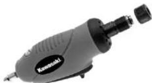
- Remove collet nut from grinding tool.
- Insert the collet, making sure that it is the correct size for your accessory, into the grinding tool.
- Replace the collet nut on the grinding tool.
- Insert accessory through the collet nut and into the collet, pushing the accessory until it stops, then pull it out approximately 1/16 In. (1.59 mm)
OPERATION
- Select proper accessory to match application.
- Be sure accessory is properly tightened (see assembly instructions).
- Depress safety lock.
- Squeeze trigger lever to control speed.
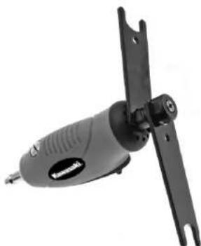

- Tighten collet nut using the spanner wrenches provided.
- Connect tool to air source by connecting air hose to air inlet.
MAINTENANCE
AIR SUPPLY
Always use clean dry air as excessive moisture will lower the available torque and rust the interior moving parts. Make sure all hoses and fittings are of the recommended size and be sure the units are not used with less than or more than the recommended pressure at the tool! (90 PSI)
LUBRICATION
Proper lubrication of this air tool is critical to the operation and life of the unit. Units can be severely damaged or have excessive wear placed on working parts if not lubricated. We recommend the use of Marvel Mystery Oil which is available at most auto parts locations. The tool should be lubricated each time it is used. During daily prolonged use, lube heavily 3 or 4 times during the day.
MAINTENANCE
Daily – before putting the tool in operation, disconnect air hose and pour about one tablespoonful of Marvel Mystery Oil into tool air inlet. Blow out air line to clear it of accumulated dirt and moisture. Connect tool and operate tool to allow oil to be carried to the interior of the tool.
ACCESSORIES
Use only accessories that are recommended by the manufacturer for your model. Accessories that may be suitable for one tool may become hazardous when used on another tool.
TROUBLESHOOTING
Most minor problems can be resolved quickly and easily using the troubleshooting table below.
PROBLEM
POSSIBLE CAUSE
SOLUTION
| Unit will not work | Plugged air inletsInterior rusted | Remove fitting and cleanDisassemble, clean, lubeand reassemble |
| Unit lacks power | Low air supplyLack of lubrication | Check hoses, tanks, etc.Lube properly and retry |
| Internal parts | Dirty or gummedComponents worn | Disassemble, clean, lubeDisassemble, determineparts requiring replacement and repair |
PARTS DIAGRAM

PARTS LIST
| NO. | PART NO. | DESCRIPTION | QTY. |
| 1 | XP-1111-01-01B | Male Plug | 1 |
| 2 | XPC-DG14-02 | Housing | 1 |
| 3 | XPC-DG14-03 | Trigger | 1 |
| 4 | XPC-DG14-04 | Spring | 1 |
| 5 | XPC-DG14-05 | Push Button | 1 |
| 6 | XPC-DG14-06 | Pin (2*27 8) | 1 |
| 7 | XP-SP-25300 | Pin (2 5*30) | 1 |
| 8 | XP-BB-06261 | Ball Bearing (626ZZ) | 1 |
| 9 | XP-SB-004 | Steel Ball 2 5 | 2 |
PARTS LIST
| NO. | PART NO. | DESCRIPTION | QTY. |
| 10 | XP-DG-14-14 | End Plate | 1 |
| 11 | XP-DG-14-12 | Rotor | 1 |
| 12 | XP-DG-14-13 | Rotor Blade | 4 |
| 13 | XP-DG-14-11 | Cylinder | 1 |
| 14 | XP-DG-14-07 | Washer | 1 |
| 15 | XP-DG-14-09 | Front End Plate | 1 |
| 16 | XP-SP-25060 | Pin (2 5*6) | 1 |
| 17 | XP-BB-60002 | Ball Bearing (6000ZZ) | 1 |
| 18 | XP-DG-140-6 | Spindle | 1 |
| 19 | XPC-DG14-19 | Retainer | 1 |
| 20 | XPC-DG14-20 | Housing Cap | 1 |
| 20A | XP-DG140-3 | Collet (6mm) | 1 |
| 21 | XP-DG140-3A | Collet 1/4 in. | 1 |
| 22 | XP-DG-14-02 | Collet Nut | 1 |
| 23 | XPC-DG1423 | Valve Stem | 1 |
| 24 | XP-ORP-0032 | O Ring (3*2) | 1 |
| 25 | XP-AR38-02 | Spring | 1 |
| 26 | XP-ORP-0080 | O Ring (P8) | 1 |
| 27 | XP-AR38PM-02 | Throttle Plug | 1 |
SPECIFICATIONS
SPECIFICATIONS
| No Load Speed 17,000 RPM | |
| Air Inlet 1/4 in. (6.35 mm) NPT | |
| Air Consumption 4-9 CFM | |
| Recommended Air Pressure | 90 PSI |
| Suggested Air Hose Size | 3/8 in. (9.52 mm) |





- CONGRATULATIONS
- INTENDED USE
- GENERAL SAFETY RULES
- WARNING
- SAVE THESE INSTRUCTIONS FOR FUTURE REFERENCE
- RECOGNIZE SAFETY SYMBOLS, WORDS AND LABELS
- DANGER
- CAUTION
- NOTE
- IMPORTANT SAFEGUARDS
- SERVICE
- SPECIFIC SAFETY RULES AND/OR SYMBOLS
- IMPORTANT SAFETY RULES FOR AIR TOOLS
- FUNCTIONAL DESCRIPTION
- ASSEMBLY
- OPERATION
- MAINTENANCE
- AIR SUPPLY
- LUBRICATION
- ACCESSORIES
- TROUBLESHOOTING
- SPECIFICATIONS
Brand : KAWASAKI
Model : 840772
Category : Grinder