
CLW-DIMEX-P - Dimmer Crestron - Free user manual and instructions
Find the device manual for free CLW-DIMEX-P Crestron in PDF.


| Product Type | Dimmer Switch |
| Brand | Crestron |
| Model | CLW-DIMEX-P |
| Dimensions | 2.5" x 1.8" x 1.6" (63.5 x 45.7 x 40.6 mm) |
| Weight | 0.2 lb (90 g) |
| Power Supply | 120 VAC, 60 Hz |
| Max Load | 600 W (incandescent) / 300 VA (LED/CFL) |
| Dimming Type | Forward Phase (Leading Edge) |
| Compatible Loads | Incandescent, LED, CFL, MLV, ELV |
| Control | Local button and remote via Crestron system |
| Mounting | In-wall, single gang |
| Material | Flame retardant plastic |
| Color | White |
| Certifications | UL, cUL, FCC |
| Warranty | 3 years |
| Operating Temperature | 32°F to 104°F (0°C to 40°C) |
| Humidity | 5% to 95% non-condensing |
| Protection | Overload and short-circuit |
| Maintenance | Wipe with a dry cloth |
| Cleaning | Avoid abrasive cleaners |
| Safety | Turn off circuit before installation |
| Spare Parts | Not available (integrated unit) |
| Repairability | Not user-serviceable |
Frequently Asked Questions - CLW-DIMEX-P Crestron
User questions about CLW-DIMEX-P Crestron
0 question about this device. Answer the ones you know or ask your own.
Ask a new question about this device
Download the instructions for your Dimmer in PDF format for free! Find your manual CLW-DIMEX-P - Crestron and take your electronic device back in hand. On this page are published all the documents necessary for the use of your device. CLW-DIMEX-P by Crestron.
USER MANUAL CLW-DIMEX-P Crestron
The Creston® CLW-DIMEX P is a Camero® in wall diameter that features field replaceable, ergravable buttons. Along with the entire line of new Camero products, it can be configured with various button layout and design colors, making the CLW-DIMEX-P more versatile and affordable than previous generation of in-wall diameters. Its extremely design matches the entire line of Camero dimmer, switches, and keyside, making it a great addition to new or retrofit installations. In addition to its attractive look and fast, iNET EX® communication technology brings proven reliability to the CLW-DIMEX-P.
CHINA INDEX SPDRUST
| SPECIFICATION | DETAILS |
| Load Ratings | |
| Inconocent or Transpens Halogens | 750 watts* |
| Magnets Low Voltage 150 V/150 watts* | |
| Minimum Load | 25 watts (with dedicated neutral comstock)50 watts (no cooling unit) |
| Power Requirements | 130 Wh, 80 Wh, linear power |
| Instrumental | |
| Temperature | 92° to 194°F to 40°C |
| Humidity | 10% to 85% 10% non-contending |
| Enclosure | * gang monoculture in 3-1/2 inch drop clove out box;Frequency controller style telegate (not standard) |
* Derating options for mitigating installations. Refer to "Autigung Installations" for more information.
Additional Resources
Visit the product page on the Crestron website (www.crestron.com) or scan the QR code to the right for additional information and the latest firmware updates.

Installation
WARNING: To avoid fire, shocks, or deaths, turn off power at circuit breaker or fuse and test that power is off before wiring!
WARNING: New installations should be checked for short circuits prior to installing a CLW-DIMLK-P dimmer. With power off, close the circuit and restore power. If the lights do not work or a breaker trip, check and correct the wiring or fixture (if necessary). Install the dimmer only when the short is no longer present. The warranty is void if the dimmer is installed and operated with a shorted load.
CAUTION: TO REDUCE THE RISK OF OVERHEATING AND POSSIBLE DWAVE TO OTHER EQUIPMENT, DO NOT INSTALL TO CONTROL A RECEPTACLE, A MOTOR-OPERATED APPLIANCE, A FLUORESCENT LIGHTING FIXTURE, OR A TRANSFORMER-SUPPLIED APPLIANCE.
ATTENTION: GRANATEURS COMMANDANT UN BALLAST, AFN DE REQUIRE LE RISQUE DE SURCHAIFFE ET LA POSSIBILITÉ D'ENDOMMAGEMENT À D'AUTRES MATÈRELS, NE PAS INSTALLER POUR COMMANDER UNE PRISE, UN APPAREL D'CLARAGE L'UROHSCENT, UN APPAREL OPÈRE DE MOTEUR OU UN APPAREL ALIMENTE PAR UN TRANSFORMATEUR.
NOTES: Observe the following points.
- Codes: This product should be installed and used in accordance with appropriate electrical codes and regulations.
- Installation: This product should be installed by a qualified electrician.
- Wiring: Use copper wire only. For supply connections, use wire rated for at least 75°C (106°F).
- Lamp Type: For use with permanently installed insandescent, magnetic low voltage, tungsten-halogen, or dimmable CFL only.
- Temperature: For use where temperatures are between 32° to 164°F to 40°C. - Electrical Boxes: Devices mount in standard electrical boxes. For easy installation, use 3.1/2 in 88 mm deep electrical boxes. Several devices can be installed in one electrical box (multigang). This requires detailing or the dimming device. For a smooth appearance, one piece multigang fasciotes (not supplied) can be installed. - Switches: Mechanical 3'- or 4-way switches do not work with CLW-DIMEX-P dimming.
- Spacing: If mounting one device above another, leave at least 4 1/2 in (115 mm) vertical space between them.
- Low Voltage Applications: Use with core and cell imagery low voltage transformers only. Do not use any solid-state electronic low voltage transformers. Operation of a low voltage circuit with all lamps inoperative or removed may result in current flow in excess of normal levels. To avoid transformer overheating and premature transformer failure, Creation recommends the following:
Do not operate low voltage circuits without operative lamps in place. Replace human-out lamps as quietly as possible.
Use transformers that incorporate thermal protection or fuse transformer primary structures in several applications (a) or due to measurement.
The following lists of the registration of a EU-UNEX-P charge:
-
Turn power off at the cim it transporter
-
Wire the device as shown in the following diagrams.
NOTE: The dinner can operate with or without a direct connection to the neutral.
NOTE: Switch made requires a dedicated neutral
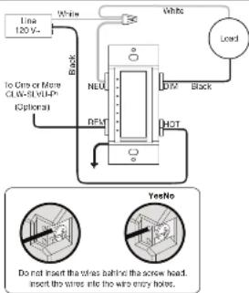
flowchart
graph TD
    A["Line 120V"] --> B["White"]
    B --> C["Load"]
    D["To Wire or More CLW-3 (M)Hz IC(splatin)"] --> E["Black"]
    E --> F["NEU"]
    F --> G["DFM"]
    G --> H["HDT"]
    H --> I["White"]
    J["Do not insert the wires behind the screw head. Insert the wires into the wire entry hole."] --> K["YesNo"]
NOTE: For optimal performance, the neutral should be connected. If the neutral is not connected, the minimum required load is 50 warts.
-
Push all power wires back into the electrical box and fasten the device to the electrical box with the provided screws.
-
Attach the decorative lacepials.
-
Ensure all buttons, including the program button, activate without sticking.
NOTE: To operate the device in Switch made, follow the instructions in "Switching Between Dim Mode and Switch Mode" before restoring power.
-
Restore power at the circuit breaker.
-
For details, refer to the CLW-SLYU-F Installation Guide (Doc. 7365) at www.credion.com/manuals.
Changing the Button Assemblies
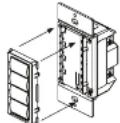
The button assembly can be removed and replaced with other button assemblies.
- Remove the button assembly by squeezing the sides of the bench near the bench frame.
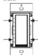
Squeeze at the arrow points and pull to remove the button assembly.
NOTE: When the button assembly is removed, power to the unit and load is recouped automatically.
- Remove the button from the front of the button assembly
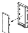
Gently spread the frame apart to remove the buttons.
- Insert the new buttons through the front of the bezel and snap them into place. Ensure that the LED strip is on the left side.
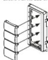
Cently spread the frame apart to heart the buttons.
- Attach button assembly to the device. Ensure that the LED strip is on the left side.
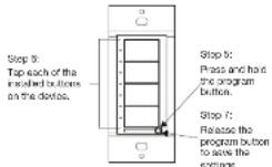
- Once power has been restored, press and hold the program button. After 5 seconds, the LEDs associated with the old button layout begin to flash. Continue to hold the button and proceed to stop 6.

CRESTRON
- While holding the program button, press all of the buttons in the new layout. The LED reel to the pressed button lights.
NOTE: If the rocker switch is installed, press the top and bottom of the rocker. 7. After all of the buttons have been pressed, release the program button to save the settings.
NOTE: Changing the button configuration allows the device's behavior. Refer to the "Default Button Functions" for details.
Multigang Installations
In murgang installations, several devices are grouped horizontally in one electrical box. For a smooth appearance, one-piece murgang faceplates (not supplied) can be installed. NOTE: When installing into a murgang box, do not fully tighter devices to the box until the faceplate has been aligned.
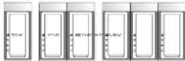
The load capacity for each device in the electrical box must be iterated. Refer to the following diagrams for desiring information. The VA ratings are for input power to the transformer. If you do not know the input power requirement of the transformer, use the bulb's wallings rating to determine proper rating.
Danating information for OLY-OMEX-P Denmark
Switching Between Dim Mode and Switch Mode
The CLW-CIMEX-P is capable of operating in Switch mode. Teggling between Dim and Switch mode is useful if the load is not dimmable or if it is preferred to not dim the load. 1. Open the six-way switch or described in "Disconnection the Power."
-
While power is off, press and hold the top and bottom button caps (regardless of button configuration) simultaneously while closing the six-gap switch.
-
After 6 seconds, the top LED blinks 8 times to indicate Dim mode or 6 times to indicate Switch mode.
-
To commit the new setting, release the buttons within the next 5 seconds.
Operation
NOTE: Before using the CLW-DIMEX-P, ensure the device is using the latest firmware. Check for the latest firmware for the CLW-DIMEX-P at www.crestron.com/firmware. Firmware is loaded onto the device using Crestron Toolbox™.
NOTE: The device may be warm to the touch during operation. This is normal. Basic Operation
The operations described in this guide assume the CLW-CIMEX P is operating in Local mode (without the use of a control system). The device can also operate in Remote mode in which button behavior is dictated entirely by the control system program. The CLW-CIMEX P is shipped with a rocker switch already installed. In this configuration, the unit functions as described below.
The LEDs indicate the load level. When all loads are off, the top LED remains firmly ill to act as a right light. In Switch mode, the top LED indicates the on or off status only. All other LEDs are off.
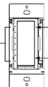
Press to turn on the load. Press and hold to raise the light level.
Press to turn off the load. Press and hold to lower the light level
- For details, refer to the CLW-SLYU-F Installation Guide (Doc. 7365) at www.credion.com/manuals.
Disconnecting the Power
Power to the dimmer and load can be disconnected by pushing on the air-cap switch.
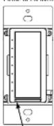
Push here to open the
air-gap
NOTE: If the climmer remains powered after the air-gap is opened, the HOT and DIM terminals have been connected in reverse. Turn all power at the circuit breaker or fuse and adjust the connections.
NOTE: Power to the load is automatically disconnected when the button assembly is removed. For instructions on removing the button assembly, refer to "Charging the Button Assemblies."
Setting Pressed Levels
The CLW-DIMEX-P can recall and store up to three periods depending on the installed button configuration.
-
Adjust the first level to the desired row.
-
Enter Programming mode by quickly tapping the program button as shown below. The LEDs of buttons that are capable of storing a preset will finish.
NOTE: Programming mode is disabled when the load is off.
- Press and hold the desired preset button until the LED blink (approximately two seconds). Release the button to store the new level.
If a button is not pressed, the device sells Programming mode after approximately five seconds.
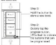
NOTE: A delayed off can be added via central system programming.
Default Button Functions
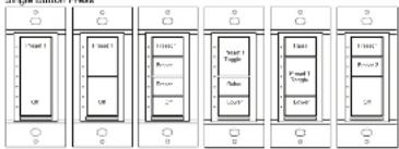
The figures below illustrate the default functions available for each physical button configuration and tap or hold actuation sequence.
Single Button Press
flowchart
graph TD
    A["Panel 1"] --> B["Block"]
    C["Panel 2"] --> D["Block"]
    E["Panel 3"] --> F["Block"]
    G["Panel 4"] --> H["Block"]
    I["Panel 5"] --> J["Block"]
    K["Panel 6"] --> L["Block"]
    M["Panel 7"] --> N["Block"]
    O["Panel 8"] --> P["Block"]
Double Button Press (Press Twice within 1/2 Second)
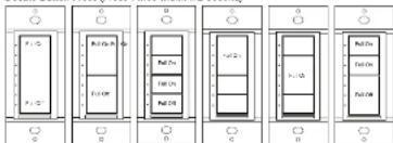
Single Button Press and Hold (Hold for More than 1/2 Second)
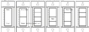
Master and Slave Operation
For more information on master and slave operation, refer to the CLW-SLVU-P installation Guide (Doc. 7384).
Wireless Communications
The device connects to the Crestron network via the intNET EX communications protocol. Use the procedures outlined below to join or leave an intNET EX network and to verify communications between the device and the control system.
Joining an infiNET EX Network
Before a device can be used in a lighting system, it must first join an InfNET EX network by being acquired by an infNFT EX gateway.
NOTE: A device can be acquired by only one gateway.
Put the ININET EX gateway into Acquire mode from the unit itself or from Creation
NOTE: In an enforcement where multiple gateways are installed, only one gateway should be in Acquire mode at any time.
- Plans the device into Acquired mode.
a. Top the top button three times, and then press and hold it down
(sp-lsp-lsp-press-built) until the top LEDs on the device flash once (this can take up to 10 seconds).
b. Release the button to start the acquire process. The top LED thinks slowly to show that the device is actively scanning the infINET EX network.
- The top two LEDs turn on for 5 seconds to show that the device has been successful by acquired to the iQFNET EX network.
- The top LED blinks test to indicate that the device was not successfully acquired
by the inNET EX network. Tag the setup button to acknowledge failure to acquire the inNET EX network. Ensure the gateway is in Acquire mode and within range before attempting the acquire process again.
- Once all devices have been acquired, take the gateway out of Acquire mode. Refer to the gateway's manual for details.
Leaving an InfNET EX Network
To leave an infinit EX network, put the device into Acquire mode, as described in "Joining an infinit EX Network" above, when no gateway is in Acquire mode.
Veribing Communications Status
To check the communications status of the device, tap the setup button three times and then press and hand it down (tap-lap-bip-press+lock) for up to 2 seconds. The LED clinics to indicate the communications status. Refer to the following table for details:
| LED | COMMUNICATIONS STATUS |
| Turns on for 5 seconds. The device is communicating with the control system. | |
| Blinks three times | The device is communicating with the gateway, but the gateway is not communicating with the control system. |
| Blinks twice | The device was previously joined to the network but is not communicating with the gateway. |
| Blinks once | The device is not joined to the network. |
Troubleshooting
The following table provides corrective action for possible trouble situations. If further assistance is required, please contact a Credium customer service representative. C105-AMC K-P Inc./Investor
| TROUBLE | PROBABLE CAUSE(S) | CORRECTIVE ACTION |
| The diameter does not function. | The diameter is until receiving line power. | Verify that the power connectors are correct and then the circuit switches is closed. |
| The load is not operational (e.g., amps are burned out). | Verify that the load is open and are that the air gap switch is closed. | |
| The device is in Remote mode. | Check the SIMPL program to verify the operating mode. | |
| The diameter does not dim. | The device is in Switch mode. | The max power from the device, nasopy power and press and hold the top and turner buttons for 5 seconds. If the LED drinks 3 times, the device is in DIM mode, if blinds 2 times, it is in Switan mode. |
| The diameter remains powered and set-jap switch is open. | The HOT and DIM threads are fixed in reverse. | Turn off power at the circuit breaker or base and adjust at the connections. |
| The diameter cycles oil occasionally when much full brightness. | The load connected is loss than 20 watts. | Increase the load on the circuit to at least 20 watts. And neutral time is required for loads less than 50 watts. |
| The load connected is loss than 50 watts. | Connect the neutral to the diameter. |
This product is listed to applicable UL Standards and requirements by Underwriters Laboratories Inc. c VL us
Federal Communications Commission (FCC) Compliance Statement
This device complies with part *5 of the FCO Rules. Operation is subject to the following two conditions:
(3) In a dose scan may not cause natural interference, and (2) from devices must assess any interference revised including an inflammatory that was as peripheral mutation.
CAUTION: Changes or modifications not expressly approved by the manufacturer responsible for
NOTE: This equipment has been tested and found to comply with the limits for a Class B digital
davies, pursuant to part 15 of the FOG Pules. These limits are cheap and to provide reasonable product parts that harmful interference can be repeated instead of set. In a sequential manner, one
and can radiate radio frequency energy and, if not installed and used in accordance with the
The equipment shall be done to ensure that the maintenance will not occur in particular installations. If a equipment those cause harmful interference to radio or television reception, which can be determined by turning the equipment still and on, the case is encouraged to try to correct the maintenance by one or more if the following measures:
• Recipient or relocate the receiving antenna
- Increase the separation on between the equipment and receiver
- Connect the equipment into an outlet on a circuit different from that to which the receiver is connected.
021160340
Industry Canada (IC) Compliance Statement
This device complies with industry Canada license-exempt PSS standard(s). Operation is subject to the following two conditions: (1) this device may not cause interference, and (2) in a due current accept any interference, including interference that may require reduce and retention of the device.
Under industry Canada regulations, this radio transmitter may only operate using an antenna of a type and maximum (or lease) gain approved for the transmitter by industry Canada. To reduce potential radio interference to other users, the antenna type and its gain should be so chosen that the equivalent technological regulated power is not more than that necessary for successful communication.
To satisfy RF exposure requirements, this device and its antenna must operate with a separation distance of at least 20 orders from all persons and must not be colocated or operating in conjunction with any other antenna or transceiver.
The product warrants can be found at www.cation.com/warante.
The specific patents that cover Crestron products are listed at patents.crestron.com.
Creation, the Creation type, Currency, Currency Toolbox, and in NET EX are either transaction or
registered trademarks of Canadian Electronics, Inc. in the United States and/or other countries, UK, and the ill. 2006 are either trademarks or registered trademarks of Incorporated Laboratories, Inc. in the
United States anterior other countries. Other trademarks, registered trademarks, and media networks may be used in this document by law. In other the entities claiming the major and names of the products
Based in this case, it is to enter the analysis of the results and names of the products. On behalf of any proprietary interest in the market and names of others. Creation is not reasonable for growth in specialty or specialty.
This document was written by the Technical Publications department at Crestron
©2015 Coupilon Electronics, Inc.
Crestron Electronics, Inc. Operations & Installation Guide - DOC. NBNF
15 Novo 1986 - Rockberg, R. O'Brien, [2008]
Fax 251-6798
www.csc108.com
03.15
•
Brand : Crestron
Model : CLW-DIMEX-P
Category : Dimmer