
CLW-DELVEX-P - Dimmer Crestron - Free user manual and instructions
Find the device manual for free CLW-DELVEX-P Crestron in PDF.


| Product Type | Dimmer |
| Brand | Crestron |
| Model | CLW-DELVEX-P |
| Series | infiNET EX |
| Load Types Supported | Incandescent, Halogen, MLV, ELV, LED, CFL |
| Voltage | 120 V~, 60 Hz |
| Maximum Power Rating | 600 W (incandescent) / 300 W (LED/CFL) |
| Control Method | Wireless infiNET EX, 2-way RF |
| Transmission Range | Up to 150 ft (46 m) open air |
| User Interface | Raise/lower rocker; LED indicators |
| Faceplate Compatibility | Standard Decora-style wall plate (not included) |
| Available Colors | White, Black, Almond, Light Almond |
| Dimensions (H x W x D) | 2.95 x 1.75 x 1.75 in (75 x 44 x 44 mm) |
| Weight | 3.2 oz (91 g) |
| Operating Temperature | 32° to 104°F (0° to 40°C) |
| Humidity Range | 10% to 90% RH non-condensing |
| Certifications | UL, cUL, FCC |
| System Compatibility | Crestron Home, 3-Series, 4-Series control systems |
| Programming | Via Crestron Toolbox or SIMPL Windows |
| Key Features | Preset dim levels, adjustable fade rate and ramp rate |
| Maintenance | Clean with dry soft cloth; do not use liquid cleaners |
| Safety | Install per local electrical codes; disconnect power before wiring |
| Spare Parts & Repairability | No user-serviceable parts; contact Crestron for repair |
Frequently Asked Questions - CLW-DELVEX-P Crestron
User questions about CLW-DELVEX-P Crestron
0 question about this device. Answer the ones you know or ask your own.
Ask a new question about this device
Download the instructions for your Dimmer in PDF format for free! Find your manual CLW-DELVEX-P - Crestron and take your electronic device back in hand. On this page are published all the documents necessary for the use of your device. CLW-DELVEX-P by Crestron.
USER MANUAL CLW-DELVEX-P Crestron
CLW-DELVEX-E/CLW-DELVEX-P
Cameo® Wireless In-Wall ELV Dimmer, 120 V
Installation & Operation Guide

Description
The Crohnost CLW-DRV-FX-E and CLW-DRV-FX-P are carried in an end of 10 minutes designed for trimming electronic low voltage lighting, supporting lighting loads such as integer-scale slopes. Free movement, and durable LED replacement lamps. Wearable and affordable, the CLW-DELVEX-E and CLW-DELVEX-P feature field replaceable, engrowthable buttons and can be configured with various button layouts and designer keys. The CLW-DRV-FX-E and CLW-DRV-FX-P are functionally identical. For simplicity within this guide, the term "CLW-DELVEX-L/P" is used except where noted. CLW-DRV-FX-P Snackbones
| SPECIFICATIONS DETAILS | |
| Load Rating | |
| Load type | Electronic low-voltage, LLD, incandescent, tungsten halogen, electronic CFL, 2 wire fluorescent pellet |
| Maximum Load | 600 V/Watts |
| Minimum Load | 10 Vatts |
| Power Requirements 120 Vdc, 50/60 Hz, the power | |
| Locksurs 1-gang mountain | A clocked solar line and line is required. |
| in a 3-1/2 from (84 mm) crop electricity bus. | |
| Required solar store style facade (not included) | |
| Elevation machine Temperature Humidity | 32° to 194° (30° to 40°C)10% to 80% Reliopurposed gas |
Additional Resources
Visit the product page on the Crestron website (www.crestron.com) for additional information and the latest firmware updates. Use a QR reader application on your mobile device to scan the QR Image.


Important Notes
WARNING: To avoid fire, shock, or death, turn all power at the circuit breaker or fuse and test that power is off before wiring!
WARNING: Now installations should be checked for short circuits prior to installing a C-UL-DEL/FRX-R/P. dimmer. With the power off, close the cloth and then restore power if the lights do not work, or a breaker trip, check and correct the wire or fixture of necessary. Install the dimmer only when the short is no longer present. The warranty is void if the dimmer is installed and operated with a shorted load.
CAUTION: TO REDUCE THE RISK OF OVERHEATING AND POSSIBLE DAMAGE TO OTHER EQUIPMENT, DO NOT INSTALL TO CONTROL A DECEPTACLE, A MOTOR-OPERATED APPLIANCE OR A TRANSFORMER SUPPLIED APPLIANCE.
ATTENTION: GRADATEURS COMMANDANT UN BALLAST-APIN DE RÉDUIRE LE RISOLE DE SURCHAUTE ET LA POSSIBILTE C'ENDONNAMGEMENT À D'AUTRES MATÈRIELS. NE PAS INSTALLER POUR COMMANDER LIME PAISE, UN APPAREL OPERE DE VOTEUR OU UN APPAREL ALIMENTE PAR UN TRANSFORMATEUR.
NOTE: Observe the following points.
- Carbot installation with all local and radicemechanical end see
- Insulation: The product should be related by a cushioned electrician.
- W/mg. Use copper wire only. For supply connections, use wire rated for at least 75 °C.
- Lamp Type: For use with permanently installed inandescent electronics
15V voltage resistors of LED, tungsten hydrogen, or dimmered CFL only. - Temperature: For near-zero temperatures are between 30° to 10° (F) to 40 °C.
- Electrical Boxes: Devices mount in standard electrical boxes. For easy installation, Construction recommends using 3-1/2 in 28 mm deep electrical boxes. Several devices can be installed in one electrical box multigang. This requires docking of the dimming device. For a smooth appearance, one piece multigang faciplanes that include can be installed.
- Switches: Mechanical 3- or 4-way switches do not work with CLW-DEL/VX-LP
- Spacing: If mounting one device above another, leave at least 4-1/2 in [175 mm vertical space between them.
- Low voltage applications: Use with electronic low voltage transformers only.
- Do not use any magnetic low-voltage transformers.
- Operation of a low-voltage circuit with all lamps imperative or removed may result in current flow in access of normal blocks. To avoid transformer overwiring and premature transformer failure, Children recommends the following:
Do not operate low-voltage circuits without operation lamps in place
Replace burned-out lamps as quickly as possible. - Use transformers that incorporate thermal protection to prevent transformer failure due to overcurrent.
Installation
install the CLW-CELVEX-E/P.01-mir
-
I am the power off at the circuit breaker.
-
Wire the devices as shown in the following diagrams. Refer to the table that follows for wire information.
We're CLIF-CLY-DO
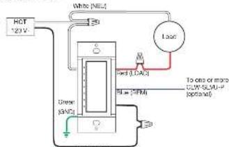
Use the CLIP-DELANCE
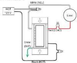
| CONNECTION WIRE GAUGE WIRE COLOR | ||
| HOT 16 AWG Rack | ||
| NEU 16 AWG White | ||
| LOAD | 16 AWG Rod | |
| FEM | 16 AWG Rule | |
| GND | 16 AWG Green | |
-
Push all power wires back into the electrical box and fasten the device to the electrical bus with the provided service.
-
Attach a decorative spectacle.
-
Ensure all buttons, including the air gap switch and program button, actuate without sticking
C. Restore power at the circuit breaker.
Changing the Button Assemblies
The bar on roseentry can be removed and replaced with other cation assemblers. To
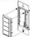
- Squeeze the sides of the base near the base steps to remove the button assembly.
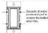
NOTE: Please to the end and close is removed automatically when the button assembly is removed.
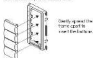
- Removes the button from the front of the buttons assembly
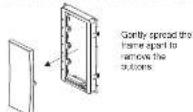
- Insert the new buttons through the front of the base and snap them into place. Ensure that the LED ship is on the left side.
- Attach the button assembly to the device. Ensure that the LED strip is on the left side.

CRESTRON
-
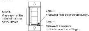
Once power has been restored, press and hold the program button. After 5 seconds, the LLDs associated with the one button layout begin to flash. Continue to hold the button and proceed to step 8.
-
While holding the program button, press all of the buttons in the new layout. The LED reset to the pressed button lights.
NOTE: If the locker switch is installed, press the top and bottom of the rocker. 7. Release the program button to save the settings after all of the buttons have been pressed.
NOTE: Changing the button configuration after the device's behavior. Refer to the "Default Button Functions" for details.
Multigang Installations
In multigang installations, several devices are grouped horizontally in one electrical box. For a smooth appearance, one place multigang foscplates not included can be installed.
NOTE: When installing into a multigang box, do not fully lighten devices to the box, and the foscplates has been aligned.
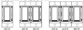
The load capacity for each device in the electrical box must be derived. Derating information is shown in the illustration below.
Derivative knowledge for CL-11L10X-L2P
Operation
NOTE: Before using the CLW-DF-VEX-FIP, ensure the device is using the latest firmware. Check for the latest firmware for the CLW-DELVEX-FIP at www.crestron.com/termware. Load the firmware onto the device using Crediron Toolset™ software.
NOTE: The device may be running operation. This is normal
Basic Operation
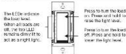
The CLV-CELVEX-E/P is shipped with a rocket switch already installed. In this
NOTE: Operation described in this guide assumes the CLW-DELVEX-DP is operating in Local mode (without the use of a control system). The device can also operate in Remote mode, in which button behavior is closed entirely by the control system program.
Disconnecting Power
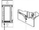
Power in the dinner and last use the connected by pushing on the six-grip switch.
Push here to open
Ar-Gap Switch in the
105 38-290 88000.
NOTE: The dimer remains powered after the air-gap is opened, the HCT and DIM terminals have been connected in reverse. Turn all power at the circuit breaker or fuse and adjust the connections.
NOTE: Power to the load is automatically disconnected when the button assembly is removed. For instructions on removing the button assembly, refer to "Changing the Button Assembly."
Setting Preset Levels
The CLW-OELVEX-E/P can read and close up to three previous depending on the installed button configuration.
Set a original level.
-
Adjust the light level to the desired level.
-
Enter Programming mode by quickly pressing the program button as shown below.
Bumors that are capable of storing a preset will flash their LEDs
NOTE: From service made is dissolved when the load is off.
- Faces and hold the desired epoch button until the LED blinks (anamalmate) two
rescris: Beigen the tution to elunt the new level.
- It is a portion is not pressed, the code exits Programming mode after approximately
the seconds
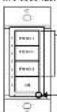
Step 3
Hold the button to
struts a new level.
Step 2
Quickly repeat the winter.
button LEDs also to
Indicate the buttons that can
be programmed
NOTE: A designed cell can be added via control system programming
Default Button Functions
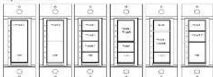
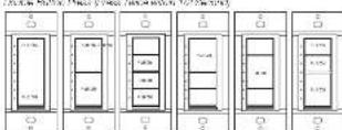
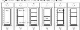
The figure below illustrates the default hand one sensitive for each physical button configuration and press or hold actuation sequence.
Na2O2
Dr. Pella Desi, Fama Tivaudita 1/20 and
[Unreadable]
Wireless Communications
The device connects to the Crostron network via the InfNET EXP communications protocol. Use the procedures outlined below to join or leave an InfNLT LX network and to verify communications between the device and the control system.
Joining an inFINET EX Network
Before a device can be used in a lighting system, it must first join an INNET EX network by being acquired by an INNET EX gateway.
NOTE: A desire can be acquired by any one gateway.
Put the x100E EX process, the domain exists here, the unit need or from Crease.
other, as described in its manual at www.cesedmu.com/cenn.sbs.
NOTE: In an environment where multiple gateways are installed, only one gateway should be in Acquire mode at any time.
Share the price plus 40% return
a. Too little too button three times, and two press and hold it down two five times
cross-hold until the top LEDs on the device last once this can take up to 10
2014.
b. Release the button to start the secure process. The top LLP flashes slowly to
show that the devices is actively searching the i6NET EX network.
- The 100 two LLDs turn on for 5 seconds to show that the device has been
successfully acquired to the inNET EX network.
The too LED fashes quickly to indicate that the device was not successfully
acquired by the or NET EX network. Press the top choice to synthesize failures
to acquire the i6NET EX network. Ensure the gateway is to Acquire mode and
within range before attempting the acquire process again.
- Once all devices have been acquired from the gateway out of Acquire's mini. Refer to the gateway's manual for details.
Leaving an infINET EX Network
To leave an infinite FX network, put the device into Acquire mode, as described in "Joining an infinite FX Network" above, when no gateway is in Acquire mode.
Verifying Communications Status
To check the communication as also as of the choice, lap the top button three times and then press and hold a down lap-lap-lap-press+held up up to 2 seconds. The LED flashes to initiate the communication select. After to the following table for choice
LED COMMUNICATIONS STATUS
| Turns on for 5 seconds The device is communicating with the control system. |
| Flashes three times The device is not communicating with the gateway, but the gateway is not communicating with the control system. |
| Flashes twice The device has previously joined to the network but is not communicating with the gateway. |
| Flashes once The device is not joined to the network. |
Troubleshooting
The following table provides corrective action for possible trouble situations. If further assistance is required, please contact a Crestron customer service representative. (11/6/05 19:45:07)
| TROUBLE | PROBABLE CAUSE(S) | CORRECTIVE ACTION |
| The dammer does not take place. | The dammer is not removing the power. | Verify that the power continues to be correct and that the circuit breaker is closed. |
| The load is not operational (e.g., large or smaller only). | Verify that the load is necessary or shall it be a step when it is closed. | |
| The device is in Remote mode. | Check the program to verify the operating mode. | |
| The motor area is not connected to the dammer. | Connect a dedicated central wire to the channel. | |
| The dammer does not claim to a low level or flickers when dammer. | The large corrected may be better suited to an alternate charging mode. | Switch the hammer to use Altamato Charging mode. Contact Geeson 1 checked support for write to Online Help Answer ID 52039. |
This product conforms to UL STD 1472; certified to USA STC 0222 No. 18C-1

-EE Dr Gentura - PDGN18901
Compliance Statement (Part 15.19)
The device comprises with Part 15 of the FOC Fuel Operation is subject to a factor below low compliance
• This device may not cause harmful incontinence, and
- This device must accept any interference received, including interference that may cause interference.
Warning (Part 15.21)
Changes of the following are independently expressed by the party responsible for compliance should be the man's authority to approve the Switzerland.
IF Exposure: OET Bulletin 65
To comply with FDC's IP exposure limits for general population/controlled exposure, in a manner that must be installed to provide a separation distance of at least 20 cm from all persons and must not be required or potentially to operate them with any other or longer or shorter.
The project was not yet that may be invested in
the specific palette that covers Goodman past, the new label of www.ceserv.com/sacol/palents
Cena in Oreston products contain open source software. For specific information, please visit
2017年1月1日
Electron, the Electron logo, Games, Chevron Toolbox, and INNET EX are other trademarks of registered trademarks of Chevron Electronics, Inc. in the United States and other securities. LLC and the UK logo are other trademarks or registered trademarks of Underwriters Laboratories, Inc. in the
We believe that the company has a large number of shares, but the share of the company is not necessarily a large share. We are based on this statement to refer to a prior the introduction of the marks and names of their products. Creation excludes any proprietary interest in the marks and names of others. Creation is not responsible for errors in accordance with the provisions.
This document was written by the Technical Publications department at Chevron.
with Canadian Electric, Inc.
Creation Electronics, Inc.
15 (2) 10-18, Fax:932-61 (4) 0764.
16.2017年1月29日
MA6-202000911
Installation & Operation Guide - DOC. 7884E
(2033164)
Specifications number in
change of the price
- Description
- Additional Resources
- Important Notes
- NOTE: Observe the following points.
- Installation
- Changing the Button Assemblies
- CRESTRON
- Multigang Installations
- Operation
- Basic Operation
- Disconnecting Power
- Push here to open
- Setting Preset Levels
- Set a original level.
- Step 3
- Default Button Functions
- Wireless Communications
- Joining an inFINET EX Network
- Leaving an infINET EX Network
- Verifying Communications Status
- Troubleshooting
- Warning (Part 15.21)
Brand : Crestron
Model : CLW-DELVEX-P
Category : Dimmer