
DSSM/E01-B1C1 - FM Transmitter Lectrosonics - Free user manual and instructions
Find the device manual for free DSSM/E01-B1C1 Lectrosonics in PDF.


| Product Type | FM Transmitter |
| Brand | Lectrosonics |
| Model | DSSM/E01-B1C1 |
| Frequency Range | 537.600 – 691.175 MHz |
| Dimensions (H x W x D) | 2.59 x 1.9 x 0.70 in (66 x 49 x 17 mm) |
| Weight | 3.5 oz (100 g) including battery |
| Power Source | Lectrosonics LB-50 rechargeable Li-ion 3.6V 1000 mAh |
| Battery Life | Up to 6.75 hrs (HDM mode), 4.5 hrs at 50 mW |
| RF Output Power | Selectable 10/25/50 mW (D2) or 4 mW (HDM); max 20 mW in B1C1 band |
| Compatibility Modes | D2 (standard digital) and HDM (high density) |
| Audio Frequency Response | 35 Hz – 20 kHz (D2), 35 Hz – 15 kHz (HDM) |
| Input Gain Range | -7 to +44 dB in 1 dB steps |
| Input Impedance | Mic: 300 Ω or 4.5 kΩ; Line: 900 Ω; Instrument: 1 MΩ |
| Audio Input Connector | Subminiature locking 3-pin (Lemo type) |
| Antenna Connector | SMA (50 Ω) |
| Display | OLED matrix screen |
| Modulation Indication | Dual bicolor LEDs (-20, -10, 0, +10 dB) |
| Encryption | Digital encryption with selectable key types (Universal, Shared, Standard, Volatile) |
| Water Resistance | IP57 rated (1 m depth for 30 min) when battery door fully latched |
| Housing Material | Machined aluminum alloy with electroless nickel finish |
| Included Accessories | Whip antennas (AMM22, AMM25), Cordura pouch, reversible belt clip, LB-50 battery |
| Optional Accessories | Charger (40117), CHSDSSM dock charging system |
| Firmware Update | Via USB using Wireless Designer software |
| Warranty | 1 year limited warranty |
Frequently Asked Questions - DSSM/E01-B1C1 Lectrosonics
User questions about DSSM/E01-B1C1 Lectrosonics
0 question about this device. Answer the ones you know or ask your own.
Ask a new question about this device
Download the instructions for your FM Transmitter in PDF format for free! Find your manual DSSM/E01-B1C1 - Lectrosonics and take your electronic device back in hand. On this page are published all the documents necessary for the use of your device. DSSM/E01-B1C1 by Lectrosonics.
USER MANUAL DSSM/E01-B1C1 Lectrosonics
Fill in for your records:
Serial Number:
Purchase Date:
What is IP57?
IP ratings indicate how resistant an electrical device is to water and common materials - like dirt, dust and sand.
The DSSM's IP57 rating indicates that it is water resistant up to 1 meter (3.2 feet) for 30 minutes - perfect for your most demanding environments.

natural_image
Water-filled glass with a small electronic device floating nearby, no visible text or symbolsWARNING: the water-resistant properties of this transmitter are only possible if the unit is fully closed before it gets wet. This requires both battery door corners to be fully latched (actuators fully towards the outside of the case) thus indicating a complete seal. After the unit gets wet, always be careful to wipe off excess moisture before opening the unit to replace the battery.

natural_image
Close-up of a black electronic device casing with two gold contacts and red directional arrows indicating ports (no visible text or symbols)Placing Battery Correctly
When placing a battery into the DSSM, place it connector end first, sliding the connection points on the battery against the connection points in the battery chamber and pressing the back of the battery down. Attempting to place it backwards to "snap into place" can result in damage to your battery or to your DSSM. There is a retainer pin in place to prevent incorrect battery insertion.

Table of Contents
Introduction......4
What Is IP57? 4
600 MHz Guard Band and the Duplex Gap....5
Battery Installation ....5
Controls and Functions....6
Modulation LEDs 6
OLED Screen....6
BATT LED 6
MENU/SEL Button 6
Power Button 6
UP and DOWN Arrow Buttons....6
Encryption Status LCD/LED Indicator Modes....6
Turning LEDs ON and OFF 7
Connectors and USB Port 7
Attaching and Removing the Microphone ....7
Operating Instructions....8
Powering On in Operating Mode....8
Powering On in Standby Mode 8
Encryption Key Missing....8
Powering Off 8
Setup Steps....9
Locking the Controls....9
Adjusting the Input Gain 9
Menu Map 10
Menu Screen Details 12
Input Menu 12
Adjusting Input Gain....12
Selecting the Low Frequency Roll-off 12
Selecting Mic/Audio Input Configuration 12
Xmit (Transmit) Menu....13
Selecting Frequency....13
Setting Transmitter Output Power 13
Rf On? 13
Compat Menu 14
Selecting the Compatibility Mode ....14
HDM Mode (High Density Transmission)....14
IR&Key Menu 14
SendFreq 14
SendAll....14
GetFreq....14
GetAll 14
KeyType 14
WipeKey 15
Setup Menu....15
Auto On....15
Remote....15
Locking/Unlocking Changes to Settings....15
DispOff....15
LED Off....15
Default....15
About....15
Microphone Wiring....16
Line Input Wiring and Use 16
Input Jack Configuration....16
IR (Infared Sync) 16
Removeable Belt Clip....17
Whip Antennas....17
LectroRM....18
Firmware Update....19
Supplied Accessories/Optional Accessories....20
Specifications 21
Troubleshooting....22
Service and Repair 23
Returning Units for Repair....23
Self-help Options for Non-Urgent Concerns....23
Introduction
The DSSM is the enhanced, fully digital successor to the SSM, while being IP57 rated for moisture and particulate resistance and offering dock charging capability.
The DSSM is ideal in theater, TV, film and broadcast where concealment is desired and water-resistance is required. The DSSM offers an extensive feature set and performance packed into an exceptionally compact housing, compatible with all current Lectrosonics digital receivers, including the DSR, DSR4, DSQD, DCR822, M2Ra and DCHR.
The DSSM includes specially developed, highly efficient circuitry for extended operating time on the rechargeable LB-50 battery. RF power selections are offered at 50, 25, and 10 mW (D2 compat mode) and a special high density (HDM) mode at 4 mW.
The servo bias input accepts mic or line level signals with a wide range of gain adjustment in 1 dB steps. Accurate indications on the display allow precise gain adjustments to be made for the maximum signal to noise ratio and minimum distortion. The limiter in the preamp can cleanly handle signal peaks over 30 dB above full modulation, allowing the input gain to be set high enough to achieve the maximum signal to noise ratio, yet provide protection against input overload.
The audio input jack is a common miniature 3-pin connector with a threaded collar adding additional ruggedness. An IR (infrared) port next to the SMA antenna mount allows transfer of frequency and compatibility mode settings.
The membrane switch panel and OLED display enable access to all adjustments and settings. The menu struc-
What is IP57?

natural_image
Water-filled glass with a small electronic device submerged in liquid, no visible text or symbolsIP ratings indicate how resistant an electrical device is to water and common materials - like dirt, dust and sand.
The DSSM's IP57 rating indicates that that it is water resistant up to 1 meter (3.2 feet) for 30 minutes - perfect for your most demanding environments.
ture is easy to navigate. Battery status is indicated by a bi-color LED that is green with a fresh battery, then turns to red as the battery runs down, and finally starts blinking red when there are only a few minutes of runtime remaining.
The housing is constructed of machined aluminum alloy, treated in the conductive, super hard electroless nickel ebENi finish.
A flexible, repositionable wire belt clip (to orient the antenna facing up or down) is included.
The optional CHSDSSM battery charging station (shown below) provides a convenient and organized means of recharging up to 4 LB-50 batteries or DSSM transmitters in larger systems with numerous batteries in regular use. Each charging module may be daisy-chained to 3 additional modules using a single AC-DC power supply. (DCR5/9AU - not included) for a total of 16 units charging at once.

natural_image
Black electronic device with attached wireless network and power cord, no visible text or symbols on main body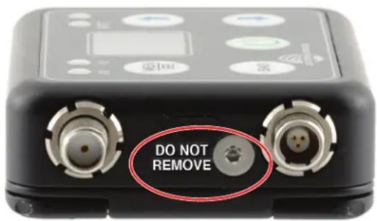
CAUTION: DO NOT REMOVE the threaded screw where indicated, as that will void the warranty and IP rating.
600MHz Wireless Guard Band and Duplex Gap
You'll notice that our B1C1 range for North America takes advantage of two portions of the spectrum within the 600 MHz band, as designated by the FCC. The 600 MHz band is made up of the following four parts:
● Guard Band (614-617 MHz)
● Downlink Band (617-652 MHz)
• Duplex Gap (652-663 MHz)
● Uplink Band (663-698 MHz)
Wireless microphone devices in North America are limited to the Guard Band (614-617 MHz) and Duplex Gap (652-663 MHz), and a maximum of 20 mW RF power.
The Guard Band consists of:
● 614-616 MHz: 2 MHz (unlicensed operators)
● 616-617 MHz: 1 MHz buffer (unavailable for use)
The Duplex Gap consists of:
● 652-653 MHz: 1 MHz buffer (unavailable for use)
● 653-657 MHz: 4 MHz (licensed operators only)
● 657-663 MHz: 6 MHz (unlicensed and WSDs)
Power is limited to 20mW for wireless microphones used in this part of the spectrum.

other
| UHF | RAS | GB | 600 MHz Downlink | Duplex Gap | 600 MHz Uplink | 700 MHz Unlicensed | |---|---|---|---|---|---|---| | 35 | 36 | 37 | 3 | 11 | A | 698 MHz | | 614 MHz | 617 MHz | 614 MHz | 652 MHz | 663 MHz | 698 MHz | 698 MHz |Battery Installation
The battery compartment and door catch are designed for simple and quick battery changes while preventing the door from being opened accidentally. Press both release catches inward to open.

natural_image
Close-up of a black electronic device with three gold contacts and red circular annotations pointing to the bottom two ports (no readable text or symbols)CAUTION: Use only the Lectrosonics LB50 battery and Lectrosonics battery chargers.
WARNING: Risk of fire or explosion if the battery is replaced by an incorrect type.
Insert battery into compartment, contact end first. Line the contacts on the battery up with the contacts on the unit, then press the back end of the battery into compartment.

natural_image
Close-up of a black battery pack with a blue card partially inserted, showing internal components and no visible text or symbols.WARNING: Water resistance requires both battery door corners to be fully latched (actuators fully towards the outside of the case) thus indicating a complete seal. After the unit gets wet, always be careful to wipe off excess moisture before opening the unit to replace the battery.

natural_image
Close-up of a black electronic device with two gold pins and red directional arrows indicating ports (no visible text or symbols)Controls and Functions
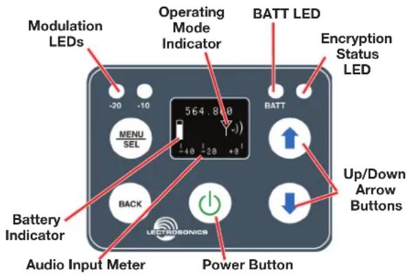
Modulation LEDs
Proper input gain adjustment is critical to ensure the best audio quality. Two bicolor LEDs will glow either red or green to accurately indicate modulation levels. The input circuitry includes a wide range DSP controlled limiter to prevent distortion at high input levels.
It is important to set the gain (audio level) high enough to achieve full modulation during louder peaks in the audio. The limiter can handle over 30 dB of level above full modulation, so with an optimum setting, the LEDs will flash red during use. If the LEDs never flash red, the gain is too low. In the table below, +0 dB indicates full modulation. See the Adjusting Input Gain section for additional information.
Signal Level -20 LED -10 LED
| Less than -20 dB | Off | Off | ● | ● |
| -20 dB to -10 dB | Green | Off | ● | |
| -10 dB to +0 dB | Green | Green | ● | |
| +0 dB to +10 dB | Red | Green | ● | |
| Greater than +10 db | Red | Red | ● |
OLED Screen
The display is a matrix OLED with menus and screens for adjusting various modes and options.
BATT LED and Battery Indicator
The battery LED glows green when the battery is good, and the battery icon is solid and steady. The LED color changes to red when there is limited operating time remaining. When the battery is extremely low and the unit is about to turn off, the LED will blink, a few minutes before the unit powers itself down.
The exact point at which the LED turns red will vary with temperature and current drain. The LED is intended to simply catch your attention, not to be an exact indicator of remaining time.
The LED next to the BATT LED (Encryption Status) will glow blue if the unit is transmitting and has a valid encryption key.
MENU/SEL Button
The MENU/SEL button is used to access the MENU tree. The ⏻ and ⚪ arrows allow you to scroll through the list. Pressing MENU/SEL again allows you to access that selection's submenu. Pressing the BACK button returns you to the previous screen. Pressing and holding the MENU/SEL button while on the home screen will bring up the Input Gain screen for quick adjustment.
Power Button
Turns the unit on and off. A brief press turns power on in a Standby Mode to make settings without interfering with other wireless systems in the vicinity. Pressing and holding the button until a bar on the display completes a sequence turns the power on with the RF output turned on. Pressing and holding for the duration of a bar sequence turns the unit off.
Audio Input Meter
This shows the audio signal level on a scale of -40 to +0 dB. A small box with the letter "L" will appear at the far right when the audio signal goes into limiting.
UP and DOWN Arrow Buttons
The ⏻ and ⏻ arrow buttons are used to select the values on the various setup screens and to lock out the control panel.
Encryption Status LCD/LED Indicator Modes

- StandBy: Blue LED is OFF and Operating Mode Indicator icon has a line through it
- Missing/Wrong Key: LED is FLASHING when unit is transmitting, along with <-KEY?-> flashing below the Operating Mode Indicator.
- Transmitting: Blue Light is steadily ON when key is valid.
Turning LEDs ON and OFF (Shortcut)

From the main “home” screen, the arrow keys also turn the LEDs on and off. With no other button pressed, the ↑ arrow turns the LEDs on and the ↓ arrow turns them off. They can also be turned off or set to constantly stay on via the Set Up menu (see page 15).
Connectors and USB Port
The housing is machined out of solid aluminum alloy for a rugged, lightweight assembly.
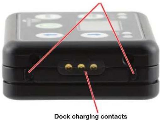
The bottom of the unit contains the battery door latches and release tabs, along with the dock charging contacts.
Battery door release tabs
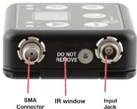
The antenna attaches via SMA connector. The IR port is capped with a translucent window to broaden the reception angle. The input jack is a rugged, watertight 3-pin connector with a threaded locking sleeve.
The battery compartment has a Gore-Tex ^® sealed vent.

natural_image
Black and red plastic device casing with circular vent and handle (no text or symbols visible)The USB port, which is used for firmware updates, is located inside the battery compartment. When connected, the unit is powered from the USB source.

natural_image
Close-up of a black electronic device casing with a red oval highlight and multiple pins (no text or symbols visible)Attaching and Removing the Microphone
Align the ridges on the plug with the grooves in the jack and insert the plug.

natural_image
Close-up of a black mechanical device with metallic connectors and a yellow cable, no visible text or symbols.Slide the threaded sleeve onto the jack and rotate it clockwise to tighten it.
Rotate it counter-clockwise to remove it.
Operating Instructions
Powering On in Operating Mode
Press and hold the Power Button Ⓞ for several seconds while "Hold for RF" appears and a bar indicator on the LCD progresses across the screen, returning to the Main Screen.

When you release the button, the unit will be operational with the RF output turned on and the Main Window displayed.
Powering On in Standby Mode
A brief press of the Power Button ⏻ releasing it before the progress bar is complete, will turn the unit on with the RF output turned off. The LCD will display a reminder that the RF output of the transmitter is turned off. Stand-by Mode means no transmission.
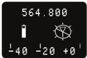
In this Standby Mode the frequency can be browsed to make adjustments without the risk of interfering with other wireless systems nearby.
After adjustments are made, press the Power Button again to turn the unit off.
Encryption Key Missing
A blinking <-KEY?-> below the Operating Mode Indicator shows that the Encryption Key is missing. Refer to page 14 for instructions on setting the Encryption Key.
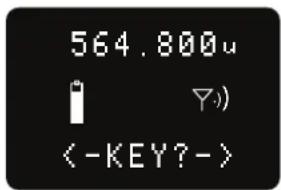
The DSSM ships with the key type set as “Universal” and will work right away with any receiver also set to Universal Key Type.
Powering Off
To power off the unit, press and hold the Power Button ⏻ and wait for the bar counter to decrease fully.

If the power button is released before the countdown is completed, the unit will remain turned on and the LCD will return to the same screen or menu that was displayed previously.
Setup Steps
The top level menus are accessed by powering the unit on, then pressing MENU/SEL. Refer to the Setup Screens section for details of each setup parameter.
The following list outlines the steps necessary to set up the transmitter for normal use.
1) Install a charged Lectrosonics LB-50 battery or retrieve the charged unit from the charging dock.
2) Set the compatibility mode to match the receiver to be used by pressing MENU/SEL, then scrolling to COMPAT and pressing MENU/SEL again to choose either D2 or HDM.
3) Adjust the frequency to match the receiver by using IR sync or use the menu system. Press MENU/SEL to open the Top Menu and choose XMIT, then Freq. Use the UP and DOWN arrow buttons to adjust the frequency in 1MHz steps. Press MENU/SEL to advance to the kHz setting and adjust as needed.
The frequency is normally determined using the receiver to identify a clear channel in the operating spectrum. Refer to the receiver instructions for details on using features such as frequency scanning.
4) Connect the microphone or audio source to be used. Select the correct input configuration.
5) Adjust the input gain. Refer to the Adjusting the Input Gain section on the following page for instructions.
6) Turn on the receiver and verify that solid RF and audio signals are present (see receiver manual).
Locking the Controls
Front panel controls can be locked in the SETUP menu. Choose Locked? and the UP and DOWN arrow buttons use the arrow button to scroll down to Locked? Use the UP and DOWN arrow buttons to choose the Yes option. To unlock, choose No.
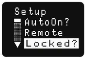

NOTE: If the unit is Locked, you must unlock it to turn the power off. This setting prevents accidentally turning off the power when in use.
Adjusting the Input Gain
The two bicolor Modulation LEDs on the control panel provide a visual indication of the audio signal level entering the transmitter. The LEDs will glow either red or green to indicate modulation levels as shown in the following table:
Signal Level -20 LED -10 LED
| Less than -20 dB | ● Off Off ● | ||
| -20 dB to -10 dB | ● Green Off ● | ||
| -10 dB to +0 dB | Green Green | ● | |
| +0 dB to +10 dB | Red Green | ● | |
| Greater than +10 dB | Red Red | ● | |
NOTE: Full modulation is achieved at 0 dB, when the “-20” LED first turns red. The limiter can cleanly handle peaks up to 30 dB above this point.
It is best to go through the following procedure with the transmitter in the standby mode so that no audio will enter the sound system or recorder during adjustment.
1) With a charged battery in the transmitter, power the unit on.
2) Press the MENU/SEL button to open the Top Menu. Choose INPUT then GAIN, to open the Gain menu.
3) Prepare the signal source. Position a microphone the way it will be used in actual operation and have the user speak or sing at the loudest level that occurs during use, or set the output level of the instrument or audio device to the maximum level that will be used.
4) Use the and arrow buttons to adjust the gain until the -10 dB glows green and the -20 dB LED starts to flicker red during the loudest peaks in the audio.
5) Once the audio gain has been set, the signal can be sent through the sound system for overall level adjustments, monitor settings, etc.
6) If the audio output level of the receiver is too high or low, use only the controls on the receiver to make adjustments. Unless the microphone or its position changes, or a different instrument is being used, leave the transmitter gain adjustment set according to these instructions. Use the audio output level control on the receiver to make adjustments for the desired level being delivered to the connected mixer, recorder, etc.
7) A shortcut to the input gain adjustment is available from the home screen. Pressing and holding the MENU/SEL button will bring up the Input Gain screen for quick adjustments.
Menu Map

flowchart
graph TD
    A["Input"] --> B["Gain"]
    B --> C["Rolloff"]
    C --> D["InpCfg"]
    D --> E["Freq."]
    E --> F["TxPower"]
    F --> G["Rf On?"]
    G --> H["Compat"]
    H --> I["IR & Keys"]
    I --> J["Send Freq"]
    J --> K["Send All"]
    K --> L["Get Freq"]
    L --> M["Key Type"]
    M --> N["WipeKey?"]
    N --> O["Toggle option with arrow buttons"]

    style A fill:#f9f,stroke:#333
    style B fill:#f9f,stroke:#333
    style C fill:#f9f,stroke:#333
    style D fill:#f9f,stroke:#333
    style E fill:#f9f,stroke:#333
    style F fill:#f9f,stroke:#333
    style G fill:#f9f,stroke:#333
    style H fill:#f9f,stroke:#333
    style I fill:#f9f,stroke:#333
    style J fill:#f9f,stroke:#333
    style K fill:#f9f,stroke:#333
    style L fill:#f9f,stroke:#333
    style M fill:#f9f,stroke:#333
    style N fill:#f9f,stroke:#333
    style O fill:#f9f,stroke:#333

flowchart
graph TD
    A["Setup"] --> B["Auto On?"]
    B --> C["Remote"]
    C --> D["Locked?"]
    D --> E["DispOff"]
    E --> F["LED Off"]
    F --> G["Default"]
    G --> H["About"]

    subgraph Setup
        I["MENU_SEL"] --> J["Auto On?"]
        J --> K["Remote"]
        K --> L["Locked?"]
        L --> M["DispOff"]
        M --> N["LED Off"]
        N --> O["Default"]
        O --> P["About"]

    end

    subgraph Options
        Q["Auto On?"]
        Q --> R["No"]
        Q --> S["Yes"]
        T["Remote"]
        T --> U["Enable"]
        T --> V["Ignore"]
        W["Locked?"]
        W --> X["Yes"]
        W --> Y["No"]
        Z["DispOff"]
        Z --> AA["On"]
        Z --> AB["30 sec"]
        Z --> AC["5 sec"]
        AD["Leds"]
        AD --> AE["On"]
        AD --> AF["Off"]
        AG["Restore?"]
        AG --> AH["No"]
        AG --> AI["Yes"]
    end

    subgraph Options
        AJ["To select and return"] --> AK["↑"]
        AL["↓"] --> AM["↓"]
        AN["BACK"] --> AO["→"]
    end

    style Setup fill:#f9f,stroke:#333
    style Options fill:#ccf,stroke:#333
Menu Screen Details
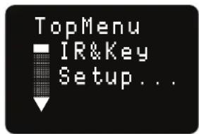
Top Menu
From the Home screen, pressing MENU/SEL will access the Top Menu. The Top Menu allows the user to access the various sub-menus to change settings on the unit.
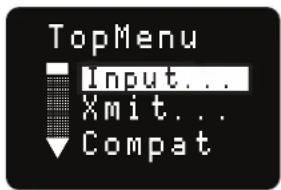
Input Menu
From the TopMenu, use the ⏱ and ⏱ arrow buttons to highlight INPUT and press MENU/SEL.


Adjusting the Input Gain
The two bicolor Modulation LEDs on the control panel provide a visual indication of the audio signal level entering the transmitter. The LEDs will glow either red or green to indicate modulation levels as shown in the following table.
| Signal Level -20 LED -1 | 0 LED | |
| Less than -20 dB | ● Off Off | ● |
| -20 dB to -10 dB | ● Green Off | ● |
| -10 dB to +0 dB | ● Green Green | ● |
| +0 dB to +10 dB | ● Red Green | ● |
| Greater than +10 dB | ● Red Red | ● |
NOTE: Full modulation is achieved at 0 dB, when the “-20” LED first turns red. The limiter can cleanly handle peaks up to 30 dB above this point.
It is best to go through the following procedure with the transmitter in the standby mode so that no audio will enter the sound system or recorder during adjustment.
1) With fresh LB50 batteries in the transmitter, power the unit on.
2) Navigate to the Gain setup screen.
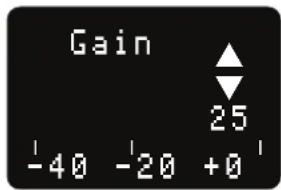
3) Prepare the signal source. Position a microphone the way it will be used in actual operation and have the user speak or sing at the loudest level that will occur during use, or set the output level of the instrument or audio device to the maximum level that will be used.
4) Use the 1 and arrow buttons to adjust the gain until the -10 dB glows green and the -20 dB LED starts to flicker red during the loudest peaks in the audio.
5) Once the audio gain has been set, the signal can be sent through the sound system for overall level adjustments, monitor settings, etc.
6) If the audio output level of the receiver is too high or low, use only the controls on the receiver to make adjustments. Always leave the transmitter gain adjustment set according to these instructions, and do not change it to adjust the audio output level of the receiver.
Selecting the Low Frequency Roll-off
It is possible that the low frequency roll-off point could affect the gain setting, so it's generally good practice to make this adjustment before adjusting the input gain.

The -3 dB down point for the roll-off can be set to:
- 35 Hz
- 100 Hz
- 50 Hz
- 120 Hz
- 70 Hz
- 150 Hz
The roll-off is often adjusted by ear while monitoring the audio to minimize low frequency noise or rumble while leaving the desired sound unaffected.
Selecting Mic/Audio Input Configuration
Audio input can be selected by using the ↑ and ↓ arrow buttons to select the InpCfg from the Input Menu and pressing MENU/SEL to select your choice.

- Instr
- PSA
• COS-11 • Oth Lav - Line In
- DPA
- MKE 2
- Dynamic
B6 M152 - Custom
The two types of high levels signals that can be used with the transmitter are:
- Line Used with line level outputs from recorders, mixers and other audio devices.
- Instr: (instrument) A special type of high impedance input with an active preamp for an optimal match with instrument pickups.
LECTROSONICS, INC.
The Custom setting allows for configuring of inputs not in the menu:

Use the arrow buttons to scroll through the available choices and use MENU/SEL to choose:
• Instr. (Pos or Neg Polarity)
• Line In (Pos or Neg Polarity)
- MicHiZ (0, 2 or 4V Bias Voltage; Pos or Neg Polarity)
- MicLoZ (0, 2 or 4V Bias Voltage; Pos or Neg Polarity)
| Option D | Description Bias Impedence | Polarity | ||
| Instr | For Line Level Input | No Bias | Instrument | Positive |
| COS-11 | Phase reversed; use for Sanken Cos-11, M152 and similar mics | 4V | MicLowZ | Negative |
| LineIn | For Line Level Input | No Bias | Line In | Positive |
| MKE2 | For Sennheiser MKE2 and similar mics | 4V | MicLowZ | Positive |
| B6 | Countryman B6 and similar mics | 2V | MicLowZ | Positive |
| PSA | For Point Source Audio and similar mics | 4V | MicLowZ | Negative |
| Oth Lav | Same as COS but audio phase not reversed | 4V | MicLowZ | Positive |
| DPA | For DPA and similar mics | 4V | MicLowZ | Negative |
| Dynamic | For dynamic mics | No Bias | MicLowZ | Positive |
| M152 | Same as Oth Lav; for easy selection of Lectrosonics 152 and similar | 4V | MicLowZ | Positive |
Xmit Menu
Use the 1 and arrow buttons to select the Transmit Menu from the TopMenu.
Selecting Frequency
The setup screen for frequency selection offers several ways to browse the available frequencies.


Rio Rancho, NM
Press MENU/SEL and use the arrow buttons to select one of three fields to adjust: MHz, KHz and Group.
Pressing the 1 and arrows changes values. The MHz frequency will change in 1 MHz steps, the KHz frequency will change in 25 KHz steps.
The GRP field allows selection of one of four user programmable frequency groups (Groups U through X), or the choice to not use groups at all. In the programmable frequency groups, up to 32 frequencies can be programmed per group. Refer to the receiver manual for group tuning information.
Use the arrow keys to cycle through the groups. Once the desired group is selected, press the MENU/SEL button to move the cursor back to the operating frequency. If the previously tuned frequency is not in the selected group, the number will flash. Now, use the ↑ and ↓ arrow buttons to scroll and select frequencies within the chosen group. These frequency numbers will not flash. Once the desired group frequency is chosen, Press BACK to return to the XMIT menu and once again to return to the home screen.
Setting Transmitter Output Power
Use the ↑ and ↓ arrow buttons to select the Transmit Menu from the TopMenu.
In D2 Compat Mode, the output power can be set to 10, 25, or 50 mW. Use the arrow buttons to scroll between and MENU/SEL to choose. In HDM Compat Mode, the RF power is set to 4 mW.


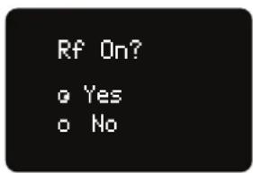
RF On?
RF transmission can be turned on or off using the ⏱ and arrow buttons.

Compat Menu
Selecting the Compatibility Mode


Use the 1 and Arrow buttons to select the desired mode, then press the BACK button twice to return to the Main Window. Compatibility modes are as follows:
• Standard Mono Digital D2
• High Density Mode HDM
HDM Mode (High Density Transmission)
This special transmitting mode and associated low RF power of 4 mW allows the user to “stack” many units into a very small area of the spectrum. Standard, ETSI-compliant RF carriers take up about 200 kHz of occupied bandwidth, while HDM takes up about half of that, or 100 kHz, and allows for much tighter channel spacing, without concern for frequency coordination.
IR&Key Menu
SendFreq
Press MENU/SEL to send the Frequency to another transmitter or receiver via the IR port.


SendAll
Press MENU/SEL to send information to a paired receiver: Frequency, Transmitter Name, and Talkback Enabled to another transmitter or receiver via the IR port.


NOTE: SendAll does not send Encryption Key. This must be done separately.
GetFreq
Press MENU/SEL to get Frequency information from another transmitter or receiver via the IR port.
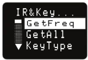

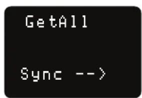
GetAll
Press MENU/SEL to get information from a paired receiver: Frequency, Transmitter Name, Talkback Enabled, and Compatibility Mode via the IR port.

KeyType
The DSSM receives an encryption key via the IR port from a key generating receiver. Begin by selecting a key type in the receiver and generating a new key (key type is labeled KEY POLICY in the DSQD receiver). Set the matching KEY TYPE in the DSSM and transfer the key from the receiver (SYNC KEY) to the DSSM via the IR ports. A confirmation message will display on the receiver display if the transfer is successful. The transmitted audio will then be encrypted and can only be listened to if the receiver has the matching encryption key.


The encryption system in Lectrosonics Digital modes D2 and HDM may be configured in four different ways, determined by a parameter known as the Key Type. The four key types range from least secure but most convenient, to most secure but least convenient. Below are descriptions of the four Key Types and how they work.
- Universal: This is the default key type, the simplest to use, and the least secure. While encryption is technically being performed and a scanner or simple demodulator would not reveal the signal content, communications are not truly secure. This is because all Lectrosonics products employing
the Universal key type use this same “universal” encryption key. With this key type selected, keys do not need to be created or exchanged, and wireless devices can be used without attention to the encryption feature.
- Shared: This is the easiest encryption mode to use while employing a uniquely generated key. This key type offers excellent security and considerable flexibility. Once a key has been created, it can be shared an unlimited number of times with any compatible device which, in turn, can also share the key. This is especially useful when multiple receivers may need to pick up various transmitters.
- Standard: The Standard key type offers enhanced security, at the cost of some complexity. Standard keys are “instance controlled”, which allows the hardware to protect against “differential attacks”. A Standard key can only be sent by the device that created it, and only up to 256 times. Unlike with Shared keys, devices receiving a Standard key cannot pass it on.
- Volatile The Volatile key type is the most secure, and also the least convenient to use. Volatile keys behave identically to Standard keys, except that they are never stored. Equipment which is turned off while using a Volatile key will come back on with no key. If a key-generating device is left on, the key can be re-shared with units in the system that have lost their keys. Once all equipment having used a given Volatile key is powered off, that key is effectively destroyed. This may be required in some highly secure installations.
WipeKey
This menu item is only available if Key Type is set to Standard, Shared or Volatile. Select Yes to clear the current key.


SetUp Menu
AutoOn
Use the UP and DOWN buttons to toggle the AutoOn feature on or off. When enabled, the transmitter will turn on to Transmit mode when a battery is replaced while the unit is running.


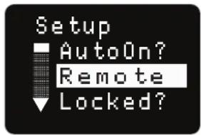
Remote
Use the UP and DOWN buttons to toggle the remote "dweedle tone" feature on or off. When enabled, the transmitter will respond to tone commands.

Locking/Unlocking Changes to Settings
Changes to the settings can be locked in this menu.


When changes are locked, several controls and actions can still be used:
- Settings can still be unlocked
- Menus can still be browsed
- When locked, POWER CAN ONLY BE TURNED OFF by removing the batteries.
DispOff
Use the UP and DOWN buttons to select the Display Off setting between 5 and 30 seconds after the last time a button is pressed, or constantly on.


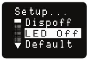
LED Off
From the main menu screen, a quick press of the the arrow button turns the control panel LEDs on. A quick press of the arrow arrow button turns them off. The buttons will be disabled if the LOCKED option is selected in the Power Button menu.

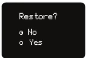
Default
Select Yes with the UP or DOWN button then press MENU/SEL to restore the Default (factory) settings.

About
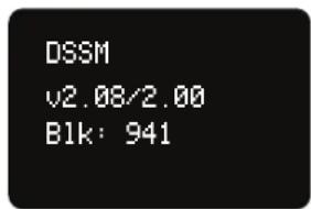
Press MENU/SEL to display the model, the firmware version, and the band/block of the unit.

Microphone Wiring
Looking into the 3 pin Lemo mic connector from the outside of the transmitter, the pin centered in the two guide slots is pin 1 (ground). Pin 2 is a 1k resistor to ground. Pin 3 is the audio/bias connection for two-wire microphones and line inputs.

Pin 1 - ground
Pin 2 - 1k source load to ground
Pin 3 - servo input
Voltages, polarity, impedance and line level for all signal sources are selected by menus. Menu selections include presets for popular microphones, and a sub-menu for manual setup. Refer to the section entitled Setup Screens on the previous page for details.
Two-wire electret lavaliere:
Pin 1 - Ground (shield)
Pin 3 - Audio and Bias
Sanken COS-11 lavaliere
Recommended Wiring:
Pin 1 - Shield (ground)
Pin 2 - White (source load)
Pin 3 - Black (bias and audio)
NOTE: The COS-11 can also be wired in a two-wire configuration. Contact Plus24/Sanken for details.
The Sanken CUB-01 is not supported.
Line and Instrument Input Wiring and Use
Pin Configuration:
Pin 1: Shield (ground)
Pin 2: Audio
Transmitter Settings:


The gain setting can be adjusted as needed for the specific input level used.
Selecting Mic/Audio Input Configuration
Refer to Page 12 for detailed information on configuring Line and Instrument level inputs.
IR Sync
An IR (infrared) link between an associated receiver and the transmitter can be used to shorten setup time and ensure that the correct settings in the transmitter are made. The window on the top panel of the transmitter is the port used for the IR link. The receiver is normally used to identify a clear operating frequency. Once step size, frequency and compatibility mode are set in the receiver, the settings can be sent to the transmitter via this IR link.
Place the transmitter close to the IR enabled receiver with the ports facing each other a few inches apart. Send the settings with the trigger on the receiver. If the settings are successfully transferred, a confirmation message will appear on the transmitter and receiver displays.
NOTE: If a mismatch exists between the receiver and transmitter, an error message will appear on the units.
Reversible Belt Clip
The belt clip may be removed or reoriented (to point the antenna up or down) by carefully lifting it out and off of the housing, with the battery door open. Pull the one side of the wire out of the grooved hole as shown, then upward to remove. Repeat for the opposite side.
Whip Antennas
Because the transmitter tunes across such a broad frequency range, it is best to use the appropriate antenna for maximum operation. Two antennas are included with the transmitter, and are shipped from the factory pre-cut and fully assembled with a 50 Ohm SMA connector.
Each antenna covers three blocks. Use the chart below to determine which antenna best fits your needs.
| Band | Block | Frequency Range MHz | Cap Color | Antenna |
| A1 | 470 | 470.100 - 495.600 | Black AMM470 | |
| 19 | 486.400 - 511.900 | Black AMM19 | ||
| 20 | 512.000 - 537.500 | Black AMM20 | ||
| B1 | 21 | 537.600 - 563.100 | Brown AMM21 | |
| 22 | 563.200 - 588.700 | Red AMM22 | ||
| 23 | 588.800 - 614.300 | Orange | AMM23 | |
| C1 | 24 | 614.400 - 639.900 | Yellow AMM24 | |
| 25 | 640.000 - 665.500 | Green AMM25 | ||
| 26 | 665.600 - 691.100 | Blue AMM26 | ||
| 941 | 941.525-959.825 | Black AMM944 |
NOTE: the DSSM/E07-941 use the AMM944 antenna
2
1
The wire rests in a small groove while placed into the mounting hole.
LectroRM
By New Endian LLC
LectroRM is a 3rd party mobile application for iOS and Android smart phone operating systems. Its purpose is to make changes to the settings on select Lectrosonics transmitters by delivering encoded audio tones to the microphone attached to the transmitter. When the tone enters the transmitter, it is decoded to make a change to a variety of different settings such as input gain, frequency and a number of others.
The app was released by New Endian, LLC in September 2011. The app is available for download and sells for \$25 on the Apple App Store and Google Play Store.
The settings and values that can be changed vary from one transmitter model to another. The complete list of available tones in the app is as follows:
- Input gain
- Frequency
- Sleep Mode
- Panel LOCK/UNLOCK
- RF output power
- Low frequency audio roll-off
- LEDs ON/OFF
The user interface involves selecting the audio sequence related to the desired change. Each version has an interface for selecting the desired setting and the desired option for that setting. Each version also has a mechanism to prevent accidental activation of the tone.
iOS


The iPhone version keeps each available setting on a separate page with the list of options for that setting. On iOS, the “Activate” toggle switch must be enabled to show the button which will then activate the tone. The iOS version’s default orientation is upside-down but can be configured to orient right-side up. The purpose for this is to orient the phone’s speaker, which is at the bottom of the device, closer to the transmitter microphone.
Android
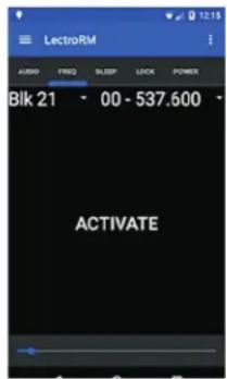

The Android version keeps all settings on the same page and allows the user to toggle between the activation buttons for each setting. The activation button must be pressed and held to activate the tone. The Android version also allows users to keep a configurable list of full sets of settings.
Remote Control and Activation
Remote control signals (“dweedle tones”) may be used to control the transmitter. The tones are played back into the microphone to avoid the need to reach and handle the transmitter when making changes to the adjustments and settings.
For a transmitter to respond to remote control audio tones, the transmitter must meet certain requirements:
- The transmitter must be turned on.
- The transmitter microphone must be within range.
- The remote control function must be enabled on the transmitter. See page 15.
Please be aware this app is not a Lectrosonics product. It is privately owned and operated by New Endian LLC, www.newendian.com.
Firmware Update
Firmware updates are made with Wireless Designer software and a file downloaded from the web site. The DSSM is connected via USB (see p. 7) to a computer running Wireless Designer.
Firmware files are located at https://lectrosonics.com/firmware.html and Wireless Designer software can be downloaded for Mac or Windows here https://lectrosonics.com/wireless-designer.html.
The USB port on the transmitter requires a micro-B male plug on the connecting cable. The other end of the cable would normally be a USB A-Type male connector to fit the most common type of USB jack used on computers. Our part number for this cable is 21926.
Step 1:
Open the DSSM battery compartment and remove the battery. Connect your computer to the DSSM using the USB cable. The transmitter will automatically power on into Update mode.

Step 2:
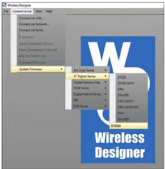
Start Wireless Designer and under the "Connect (Live)" menu, scroll down to Update Firmware, and in the D² submenu, click on DSSM.
Rio Rancho, NM
Step 3:
Follow the on-screen instructions to choose the update file, check to see if an update is needed, and initiate the update process. When finished, unplug the unit, replace the battery, and power on to RF Off mode, and check the firmware version in Setup>About to verify the update.

Supplied Accessories
AMM19
Whip Antenna with Standard SMA Connector. Block 19; included with A1B1 variant only.
AMM22
Whip antenna with Standard SMA Connector. Included with A1B1 and B1C1 variants.
AMM25
Whip antenna with Standard SMA Connector. Included with B1C1 variants only.
AMM944
Whip antenna with Standard SMA Connector. Included with 941 variants only.

natural_image
Three black coaxial connectors with colored wires (red, blue, white) against a white background, no text or symbols visible.Cordura Pouch
P/N 35939 zippered, padded; 4 x 6 x1 inches

natural_image
Blue and black plastic case with a white spoon icon on the cover (no text or symbols visible)Reversible Wire Belt Clip
Belt clip for DSSM; black wire. Reorder with P/N 27332.

natural_image
Simple line drawing of a bent pipe or handle (no text or symbols)Rechargeable battery
P/N 40106-1 LB-50 3.6V lithium-ion battery pack

Optional Accessories
40117
Charger for two Lectrosonics LB-50 batteries. USB powered

natural_image
Two black rectangular electronic devices with two cards placed on top, one showing text (no readable symbols or labels)Available with transmitter as a kit.
Use P/N ZS-DSSM-A1B1-WITH-CHARGER
CHSDSSM Dock Charging System
Provides a convenient means of recharging 4 LB-50 batteries or DSSM transmitters. Can be daisy-chained to 3 additional units (total 4) from one power supply. DCR5/9AU power supply not included.

natural_image
Two black electronic device units with multiple ports and connectors, no visible text or symbols on the devices themselves.DCR5/9AU
AC-DC power supply, for CHSDSSM

natural_image
Black USB connector with cable and connector, no visible text or symbolsSpecifications
Operating Frequencies:
DSSM - A1B1 470.100 - 607.950
DSSM/E01-A1B1: 470.100 - 614.375
DSSM-B1C1 (US) 537.600 - 607.950
614.400 - 615.950
653.050 - 662.950
DSSM/E01-B1C1: 537.600 - 691.175
DSSM/E07-941: 941.600 - 951.900
953.100 - 956.150
956.550 - 959.750
Frequency
Selection
Steps: 25 kHz
RF Power output: Selectable; 10, 25, 50 mW (D2 mode) or 4 mW (HDM mode)
20 mW max for North American B1C1 from 614.400-615.950
and 653.050-662.950
Compatibility
Modes: HDM or D2 (all models)
Frequency Stability: ± 0.002%
Spurious radiation: Compliant with ETSI EN 300 422-1
Equivalent input
noise: -120 dBV (A-weighted)
Input level: Nominal 2 mV to 300 mV, before limiting. Greater than
1V maximum, with limiting.
Input impedance: • Mic: 300 or 4.5 k ohm; selectable
- Line: 900 ohm
- Instrument: 1 M ohm
Input limiter: DSP controlled, dual envelope "soft" limiter with
greater than 30 dB range
Gain control range: -7 to +44 dB; digital control, 1 db steps
Modulation
indicators: Dual bicolor LEDs indicate modulation of -20, -10, 0
and +10 dB referenced to full modulation
Audio Performance:
Frequency Response: 35-20 kHz; 35-15 kHz (HDM compat mode)
Low frequency
roll-off: Selectable; 35, 50, 70, 100, 120, 150 Hz
THD: 0.2% (typical)
Controls: Front panel membrane switches with OLED interface
for power on/off and all setup and configuration
controls
Audio Input Jack: Subminiature; locking 3 pin
Antenna: SMA connector; coated, flexible wire, length by
frequency band
Battery: Lithium-ion 3.6 V 1000 mAH LB50 battery pack
(included)
Battery Life:
| 50 mw | 25 mW 10 mW | HDM (4mW) | |
| 4.5 Hrs | 5.0 Hrs | 6.0 Hrs | 6.75 Hrs |
Weight: 3.5 ounces (100 grams) including lithium battery pack
Dimensions
(housing): 2.59 x 1.9 x .70 in. (66 x 49 x 17 mm)
Emission
Designator: 110KG1E (HD mode); 170KG1E (D2 mode)
Specifications subject to change without notice.
For body worn operation, this transmitter model has been tested and meets the FCC RF exposure guidelines when used with the Lectrosonics accessories supplied or designated for this product. Use of other accessories may not ensure compliance with FCC RF exposure guidelines. Contact Lectrosonics if you have any questions or need more information about RF exposure using this product.
This device complies with FCC radiation exposure limits as set forth for an uncontrolled environment. This device should be installed and operated so that its antenna(s) are not co-located or operating in conjunction with any other antenna or transmitter.
This device complies with ISED Canada radiation exposure limits as set forth for a controlled “professional” use only.
It is important that you follow these steps in the sequence listed.
Symptom:
Possible
Cause:
Transmitter Battery LED off 1. Batteries are inserted incorrectly. when Power Switch "ON" 2. Batteries are low or dead.
No Transmitter Modulation LEDs when Signal Should be Present
- Gain control turned all the way down.
-
Batteries are inserted incorrectly. Check power LED.
-
Mic capsule is damaged or malfunctioning.
- Mic cable damaged or miswired.
- Instrument Cable damaged or not plugged in.
- Musical instrument output level set too low.
Receiver Indicates RF But No Audio using an alternate source or cable.
-
Audio source or cable connected to transmitter is defective. Try
-
Make sure the compatibility mode is the same on transmitter and receiver.
- Ensure musical instrument volume control is not set to minimum.
- Check for correct encryption key type is selected.
Receiver RF Indicator Off frequency.
- Ensure that the transmitter and receiver are set to the same
frequency.
- Transmitter not turned on, or battery is dead.
- Receiver antenna missing or improperly positioned.
- Operating distance is too great.
- Transmitter may be set to the Standby Mode. See page 8.
No Sound (Or Low Sound Level), Receiver Indicates Proper Audio Modulation
- Receiver output level set too low.
-
Receiver output is disconnected; cable is defective or miswired.
-
Sound system or recorder input is turned down or not enabled.
Distorted Sound
- Transmitter gain (audio level) is too high. Check Modulation
LEDs on transmitter and receiver while distortion is being heard.
- Receiver output level may be mismatched with the sound system or recorder input. Adjust output level on receiver to the correct level for the recorder, mixer or sound system.
- RF interference. Reset both transmitter and receiver to a clear channel. Use scanning function on receiver if available.
- Transmitter is at the edge of the useable range for that frequency.
Wind Noise or Breath "Pops"
-
Reposition microphone, or use a larger windscreen, or both.
-
Omni-directional mics produce less wind noise and breath pops than directional types.
Hiss and Noise -- Audible Dropouts
-
Receiver antenna missing or obstructed.
-
Operating distance too great.
- RF interference. Reset both transmitter and receiver to a clear channel. Use scanning function on receiver if available.
- Microphone capsule picking up RF noise.
Excessive Feedback (With Microphone) and/or reduce receiver output level.
-
Transmitter gain (audio level) too high. Check gain adjustment
-
Microphone too close to speaker system.
- Microphone is too far from user's mouth.
Service and Repair
If your system malfunctions, you should attempt to correct or isolate the trouble before concluding that the equipment needs repair. Make sure you have followed the setup procedure and operating instructions. Check the interconnecting cables.
We strongly recommend that you do not try to repair the equipment yourself and do not have the local repair shop attempt anything other than the simplest repair. If the repair is more complicated than a broken wire or loose connection, send the unit to the factory for repair and service. Don't attempt to adjust any controls inside the units. Once set at the factory, the various controls and trimmers do not drift with age or vibration and never require readjustment.
There are no adjustments inside that will make a malfunctioning unit start working.
LECTROSONICS' Service Department is equipped and staffed to quickly repair your equipment. In-warranty repairs are made at no charge in accordance with the terms of the warranty. Out-of-warranty repairs are charged at a modest flat rate plus parts and shipping. Since it takes almost as much time and effort to determine what is wrong as it does to make the repair, there is a charge for an exact quotation. We will be happy to quote approximate charges by phone for out-of-warranty repairs.
Returning Units for Repair
For timely service, please follow the steps below:
A. DO NOT return equipment to the factory for repair without first contacting us by email or by phone. We need to know the nature of the problem, the model number and the serial number of the equipment. We also need a phone number where you can be reached 8 A.M. to 4 P.M. (U.S. Mountain Standard Time).
B. After receiving your request, we will issue you a return authorization number (R.A.). This number will help speed your repair through our receiving and repair departments. The return authorization number must be clearly shown on the outside of the shipping container.
C. Pack the equipment carefully and ship to us, shipping costs prepaid. If necessary, we can provide you with the proper packing materials. UPS or FEDEX is usually the best way to ship the units. Heavy units should be "double-boxed" for safe transport.
D. We also strongly recommend that you insure the equipment, since we cannot be responsible for loss of or damage to equipment that you ship. Of course, we insure the equipment when we ship it back to you.
Lectrosonics USA:
Mailing address: Shipping address: Telephone:
Lectrosonics, Inc. Lectrosonics, Inc. +1 (505) 892-4501
PO Box 15900 561 Laser Rd., Suite 102 (800) 821-1121 Toll-free US/Canada
Rio Rancho, NM 87174 Rio Rancho, NM 87124 Fax +1 (505) 892-6243
USA USA
Web: E-mail:
www.lectrosonics.com service.repair@lectrosonics.com
sales@lectrosonics.com
Lectrosonics Canada:
Mailing Address:
720 Spadina Avenue,
Suite 600
Toronto, Ontario M5S 2T9
Telephone:
+1 (416) 596-2202
(877) 753-2876 Toll-free Canada
(877) 7LECTRO
Fax (416) 596-6648
E-mail:
Sales: colinb@lectrosonics.com
Service: joeb@lectrosonics.com
Self-Help Options for Non-Urgent Concerns
Our Facebook groups and weblists are a wealth of knowledge for user questions and information. Refer to:
Lectrosonics General Facebook Group: https://www.facebook.com/groups/69511015699
D Squared, Venue 2 and Wireless Designer Group: https://www.facebook.com/groups/104052953321109
The Wire Lists: https://lectrosonics.com/the-wire-lists.html
LIMITED ONE YEAR WARRANTY
The equipment is warranted for one year from date of purchase against defects in materials or workmanship provided it was purchased from an authorized dealer. This warranty does not cover equipment which has been abused or damaged by careless handling or shipping. This warranty does not apply to used or demonstrator equipment.
Should any defect develop, Lectrosonics, Inc. will, at our option, repair or replace any defective parts without charge for either parts or labor. If Lectrosonics, Inc. cannot correct the defect in your equipment, it will be replaced at no charge with a similar new item. Lectrosonics, Inc. will pay for the cost of returning your equipment to you.
This warranty applies only to items returned to Lectrosonics, Inc. or an authorized dealer, shipping costs prepaid, within one year from the date of purchase.
This Limited Warranty is governed by the laws of the State of New Mexico. It states the entire liability of Lectrosonics Inc. and the entire remedy of the purchaser for any breach of warranty as outlined above. NEITHER LECTROSONICS, INC. NOR ANYONE INVOLVED IN THE PRODUCTION OR DELIVERY OF THE EQUIPMENT SHALL BE LIABLE FOR ANY INDIRECT, SPECIAL, PUNITIVE, CONSEQUENTIAL, OR INCIDENTAL DAMAGES ARISING OUT OF THE USE OR INABILITY TO USE THIS EQUIPMENT EVEN IF LECTROSONICS, INC. HAS BEEN ADVISED OF THE POSSIBILITY OF SUCH DAMAGES. IN NO EVENT SHALL THE LIABILITY OF LECTROSONICS, INC. EXCEED THE PURCHASE PRICE OF ANY DEFECTIVE EQUIPMENT.
This warranty gives you specific legal rights. You may have additional legal rights which vary from state to state.
- What is IP57?
- Placing Battery Correctly
- Table of Contents
- Introduction
- 600MHz Wireless Guard Band and Duplex Gap
- Battery Installation
- Controls and Functions
- Modulation LEDs
- OLED Screen
- BATT LED and Battery Indicator
- MENU/SEL Button
- Power Button
- Audio Input Meter
- UP and DOWN Arrow Buttons
- Encryption Status LCD/LED Indicator Modes
- Turning LEDs ON and OFF (Shortcut)
- Connectors and USB Port
- Attaching and Removing the Microphone
- Operating Instructions
- Powering On in Operating Mode
- Powering On in Standby Mode
- Encryption Key Missing
- Powering Off
- Setup Steps
- Locking the Controls
- Adjusting the Input Gain
- Menu Map
- Menu Screen Details
- Top Menu
- Input Menu
- Selecting the Low Frequency Roll-off
- Selecting Mic/Audio Input Configuration
- Xmit Menu
- Selecting Frequency
- Setting Transmitter Output Power
- RF On?
- Compat Menu
- Selecting the Compatibility Mode
- HDM Mode (High Density Transmission)
- IR&Key Menu
- SendFreq
- SendAll
- GetFreq
- GetAll
- KeyType
- WipeKey
- SetUp Menu
- AutoOn
- Remote
- Locking/Unlocking Changes to Settings
- DispOff
- LED Off
- Default
- About
- Microphone Wiring
- Two-wire electret lavaliere:
- Sanken COS-11 lavaliere
- Line and Instrument Input Wiring and Use
- IR Sync
- Reversible Belt Clip
- Whip Antennas
- LectroRM
- By New Endian LLC
- Remote Control and Activation
- Firmware Update
- Step 1:
- Step 2:
- Step 3:
- Supplied Accessories
- AMM19
- AMM22
- AMM25
- AMM944
- Cordura Pouch
- Reversible Wire Belt Clip
- Rechargeable battery
- Optional Accessories
- 40117
- CHSDSSM Dock Charging System
- DCR5/9AU
- Specifications
- Audio Performance:
- Symptom:
- Possible
- Cause:
- No Transmitter Modulation LEDs when Signal Should be Present
- Receiver Indicates RF But No Audio using an alternate source or cable.
- Receiver RF Indicator Off frequency.
- frequency.
- No Sound (Or Low Sound Level), Receiver Indicates Proper Audio Modulation
- Distorted Sound
- Wind Noise or Breath "Pops"
- Hiss and Noise -- Audible Dropouts
- Excessive Feedback (With Microphone) and/or reduce receiver output level.
- Service and Repair
- Returning Units for Repair
- Lectrosonics USA:
- Lectrosonics Canada:
- Self-Help Options for Non-Urgent Concerns
- LIMITED ONE YEAR WARRANTY
Brand : Lectrosonics
Model : DSSM/E01-B1C1
Category : FM Transmitter