
NetWay4E1WP - Network Card/Adapter Altronix - Free user manual and instructions
Find the device manual for free NetWay4E1WP Altronix in PDF.


| Product Type | Network Adapter / PoE Injector |
| Brand | Altronix |
| Model | NetWay4E1WP |
| Ports | 4 x PoE+ (IEEE 802.3af/at) ports |
| Data Rate | 10/100/1000 Mbps |
| Power Output per Port | Up to 30W |
| Total Power Budget | 60W |
| Input Voltage | 12V DC or 24V DC (depending on model) |
| Power Input | Terminal block or barrel jack |
| Dimensions (L x W x H) | 4.5 x 3.5 x 1.2 inches (11.4 x 8.9 x 3.0 cm) |
| Weight | 0.5 lbs (0.23 kg) |
| Operating Temperature | -10°C to 50°C (14°F to 122°F) |
| Storage Temperature | -20°C to 70°C (-4°F to 158°F) |
| Humidity | 5% to 90% non-condensing |
| Mounting | Wall mountable or DIN rail compatible |
| LED Indicators | Power, Link/Activity per port |
| Protection | Overload, short circuit, surge protection |
| Certifications | UL 60950-1, CE, RoHS |
| Maintenance | Keep dry and dust-free; wipe with dry cloth |
| Safety | Do not open; risk of electric shock. Use only with specified power supply. |
| Spare Parts & Repairability | No user-serviceable parts; contact Altronix support for repairs. |
Frequently Asked Questions - NetWay4E1WP Altronix
User questions about NetWay4E1WP Altronix
0 question about this device. Answer the ones you know or ask your own.
Ask a new question about this device
Download the instructions for your Network Card/Adapter in PDF format for free! Find your manual NetWay4E1WP - Altronix and take your electronic device back in hand. On this page are published all the documents necessary for the use of your device. NetWay4E1WP by Altronix.
USER MANUAL NetWay4E1WP Altronix
- 4-port Hardened PoE Switch with Power Supply/Charger
- NEMA4/4X, IP66 rated Outdoor enclosure
NetWay4E1WPX
- 4-port Hardened PoE Switch with Power Supply/Charger
- NEMA4/4X, IP66 rated Outdoor enclosure.
- Accommodates up to four (4) 12VDC/4AH batteries
NetWay4E1X
- 4-port Hardened PoE Switch with Power Supply/Charger
- NEMA1 rated Indoor enclosure
NetWay4E1WPN
- 4-port Hardened PoE Switch
- NEMA4/4X rated outdoor enclosure
NetWay4E1PL
- 4-port Hardened PoE Switch with Power Supply/Charger
- Backplane version
NetWay4E1B
- 4-port Hardened PoE Switch
- Board Only
Installation Guide
CE

Altronix®
DOC#: NetWay4E1 Rev. 050222
More than just power. ^TM
Installing Company: ____ Service Rep. Name: ____
Address: ____ Phone #: ____
Overview:
Altronix NetWay4E1 Series Hardened PoE Switches are equipped with one (1) 1Gb SFP port and four (4) PoE IEEE802.3af/3at/ & Hi PoE ports rated at 30W each, limited to total power of the power supply employed.
Features:
Agency Listings:
• CE European Conformity.
Input:
• 115VAC, 60Hz, 2.5A or 230VAC, 50/60Hz, 1.3A.
- NetWay4E1B/NetWay4E1WPN: 48-56V UL Listed ITE power supply.
Power Output:
- Four (4) 10/100/1000 Mbps Ethernet ports rated at 30W each (limited to 120W total power).
• NetWay4E1B/NetWay4E1WPN:
Four (4) 10/100/1000 Mbps Ethernet ports rated at 30W each (depending on the power supply employed).
- IEEE 802.3af, 802.3at compliant.
SFP Ports:
• One (1) Gigabit SFP port.
Ethernet Ports:
• Four (4) 10/100/1000 Mbps ports.
- Connectivity: RJ45, auto-crossover.
- Wire type: 4-pair CAT5e or higher structured cable.
- Speed: 10/100/1000 Mbps, half/full duplex, auto negotiation.
Indicators (LED):
- Individual PoE On LEDs for each port.
- Individual IP Link status, 100/1000 Base-T/active LEDs for each port.
• ALOS LED indicates fiber connection for SFP port. - Heartbeat LED indicates proper operation of the unit.
Mechanical:
NetWay4E1B:
- Dimensions (L x W x D approx.): 6.25" x 4.5" x 1.25" (158.8mm x 142.9mm x 31.8mm).
NetWay4E1PL
- Dimensions (H x W x D approx.): 10.75" x 8.875" x 2.375" (273.1mm x 225.4mm x 60.3mm).
NetWay4E1WP, NetWay4E1WPN:
• NEMA4/4X, IP66 Rated enclosure for outdoor use.
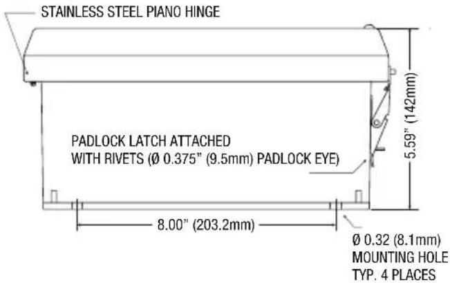
- Dimensions (H x W x D approx.): 13.31" x 11.31" x 5.59" (338.1mm x 287.3mm x 142mm).
NetWay4E1WPX:
• NEMA4/4X, IP66 Rated enclosure for outdoor use.
- Accommodates four (4) 12VDC/4AH batteries (48V of backup).
- Dimensions (H x W x D approx.):
17.53" x 15.3" x 6.67"
(445.3mm x 388.6mm x 169.4mm).
NetWay4E1X:
- Dimensions (H x W x D approx.): 13.5" x 13" x 3.25" (342.9mm x 330.2mm x 83mm).
InstallationInstructions:
Wiring methods shall be in accordance with the National Electrical Code/NFPA 70/ANSI, and with all local codes and authorities having jurisdiction. All units should be installed by a trained service personnel.
Installation:
NetWay4E1B/NetWay4E1PL:
- Mount board/backplane in the desired location/enclosure with hardware supplied.
- NetWay4E1B: Connect 56VDC/280W max power source to terminal marked [+] and [-] .
Note: For proper earth ground connections on NetWay4E1B fasten metal spacers (provided) to threaded studs at indicated board mounting holes (shown on the right).
This is recommended for better environmental immunity.

NetWay4E1WPN/NetWay4E1WP/NetWay4E1WPX:
- Remove backplane from enclosure prior to drilling. Do not discard hardware.
Note: Make sure that hardware will not interfere with components of the circuit board. - Mark and drill desired inlets on the enclosure to facilitate wiring. Maximum NEMA type 4X rated fittings to be used are 0.5". Follow manufacturer's specifications for the appropriate size opening.
Note: Inlets for conduit fittings should only be made on the bottom of the enclosure.
To facilitate wire entry utilize weather-tight NEMA rated connectors (supplied), bushings, and cable. - Clean out the inside of enclosure before remounting circuit boards/backplane.
- Mounting NEMA4/4X rated enclosure (Enclosure Dimensions, pg. 8-10):
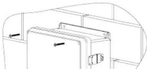
Wall mount: Mount unit in desired location. Mark and drill holes to line up with the top and bottom hole of the enclosure flange. Secure enclosure with appropriate fasteners (e.g. screws and anchors; bolts and locking nuts, etc.) that are compatible with mounting surface and are of sufficient length/construction to ensure a secure mount (Fig. 4, pg. 7).
Pole Mount: Refer to Fig. 5 - 9, pg. 7.
- Mount backplane in enclosure with hardware.
NetWay4E1X:
- Mount unit in the desired location. Mark and predrill holes in the wall to line up with the top two keyholes in the enclosure. Install two (2) upper fasteners and screws in the wall with the screw heads protruding. Place the enclosure's upper keyholes over the two (2) upper screws; level and secure. Mark the position of the lower two (2) holes. Remove the enclosure. Drill the lower holes and install two fasteners. Place the enclosure's upper keyholes over the two (2) upper screws. Install the two (2) lower screws and make sure to tighten all screws (Enclosure Dimensions, pg. 9). Secure enclosure to earth ground.
Power Connection:
-
NetWay4E1WP, NetWay4E1WPX, NetWay4E1X, and NetWay4E1PL: Before powering unit, set input voltage selection switch to proper Input Voltage position (Fig. 3a, pg. 6). Units are factory set for 115VAC.
-
Secure cabinet to earth ground. Connect AC power from overcurrent protective device circuit breaker (20A @ 115VAC, 60Hz, 16A @ 230VAC, 50/60Hz) to the terminals marked [L, N] on power supply board (Fig. 3, pg. 6). Use 14AWG or larger for all power connections (Battery, DC output, AC input).
Connect ground lug to earth or green branch wire (12AWG min.).
Keep power-limited wiring separate from non power-limited wiring by utilizing separate knockouts/inlets. Minimum 0.25" spacing must be provided.
CAUTION: Do not touch exposed metal parts. Shut branch circuit power before installing or servicing equipment. There are no user serviceable parts inside. Refer installation and servicing to qualified service personnel.
Input/Data Connections:
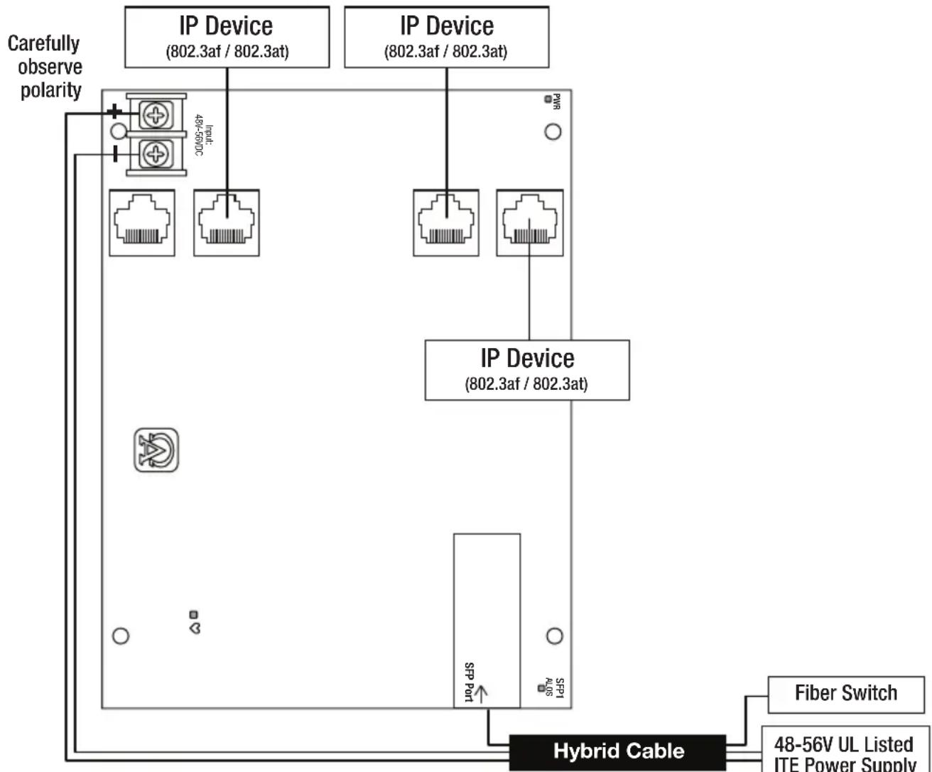
- Connect structured cables from port marked [Port 1] to [Port 4] on NetWay unit to PoE compliant cameras/edge devices (Fig. 2, pg. 5).
- Insert SFP module into port marked [SFP], then connect cable to the SFP module on NetWay4E1B to the corresponding input of an SFP switch (Fig. 2, pg. 5).
Recommended Altronix SFP Modules:
Altronix P1MM, P1SM10, P1AB2K and P1GCE are hot-pluggable SFP fiber transceiver modules and are readily usable with all Altronix Spectrum fiber optic equipment for 1Gb transmission rates.
P1MM For use with Multi-Mode Fiber for distances up to 550m.
P1SM10 For use with Single-Mode Fiber for distances up to 10km.
P1AB2K For use with Single Strand Single-Mode Fiber for distances up to 2km.
P1GCE For use with CAT5e or better for distances up to 100m.
Recommended Altronix Power Sourcing Equipment:
NetWaySP4P Ethernet to Fiber Media Converter with Integral Power Supply/Charger.
Four (4) 56VDC non power-limited outputs up to 120W max. full power per port (240W total power). Four (4) 1Gb SFP ports.
NetWaySP4PX Ethernet to Fiber Media Converter with Integral Power Supply/Charger.
Four (4) 56VDC non power-limited outputs up to 120W max. full power per port (480W total power). Four (4) 1Gb SFP ports.
NetWaySP4P2 Ethernet to Fiber Media Converter with Integral Power-Limited Power Supply/Charger.
Four (4) 56VDC power-limited outputs up to 60W max. full power per port
(240W total power). Four (4) 1Gb SFP ports.
WayPoint562 High Current Outdoor Power Supply/Charger. 56VDC/120W output.
Filtered and electronically regulated output. Short circuit and thermal overload protection.
Vertiline563 EIA 19" 1U Rack Mountable Dual Independent Power Supply/Charger.
56VDC @ 3A each output.
Filtered and electronically regulated output. Short circuit and thermal overload protection.
PoE201 Power Supply/Charger Board. 56VDC/120W output.
Filtered and electronically regulated output. Short circuit and thermal overload protection.
Technical Specifications:
| Parameter Description | |||
| Number of Ports | Four (4) 10/100/1000 Mbps Ethernet ports rated at 30W each. IEEE 802.3af, 802.3at compliant. One (1) Gigabit SFP Port. | ||
| Input Power Requirements | NetWay4E1WP/NetWay4E1PL/NetWay4E1WPX/NetWay4E1X: 115VAC, 60Hz, 2.5A or 230VAC, 50/60Hz, 1.3A. NetWay4E1B/NetWay4E1WPN: 48-56V UL Listed ITE power supply. | ||
| Environmental Conditions | Operating Ambient Temperature: 60W: -40°C to 75°C (-40°F to 167°F); 75W: -40°C to 70°C (-40°F to 158°F); 100W: -40°C to 55°C (-40°F to 131°F); 120W: -40°C to 45°C (-40°F to 113°F). Storage Temperature: -30°C to 85°C (-22°F to 185°F). Relative Humidity: 85%, +/- 5% Operating Altitude: -304.8 to 2,000m. | ||
| Weights (approx.) | Model | Product Weight | Shipping Weight |
| NetWay4E1WP NetWay4E1WPN NetWay4E1WPX NetWay4E1X NetWay4E1PL NetWay4E1B | 10.5 lb. (4.76 kg) 9.5 lb. (4.3 kg) 15 lb. (6.8 kg) 6.65 lb. (3.02 kg) 2.6 lb. (1.18 kg) 0.4 lb. (0.18 kg) | 11.9 lb. (5.4 kg) 10.9 lb. (4.9 kg) 17.5 lb. (7.9kg) 7.55 lb. (3.42kg) 4.0 lb. (1.81kg) 0.75 lb. (0.34 kg) | |
Typical Applications:
Fig. 2 - NetWay4E1B/NetWay4E1WPN – Typical Application with Hybrid Cable
flowchart
graph TD
    A["IP Device (802.3af / 802.3at)"] --> B["48-56V"]
    C["IP Device (802.3af / 802.3at)"] --> D["48-56V"]
    E["IP Device (802.3af / 802.3at)"] --> F["48-56V"]
    G["IP Device (802.3af / 802.3at)"] --> H["48-56V"]
    I["IP Device (802.3af / 802.3at)"] --> J["48-56V"]
    K["Fiber Switch"] --> L["48-56V UL Listed ITE Power Supply"]
    M["Carefully observe polarity"] --> N["+"]
    O["Input"] --> P["+"]
    Q["SPPT port"] --> R["SPPT"]
    S["48-56V UL Listed ITE Power Supply"] --> T["48-56V UL Listed ITE Power Supply"]
    U["48-56V UL Listed ITE Power Supply"] --> V["48-56V UL Listed ITE Power Supply"]
    W["48-56V UL Listed ITE Power Supply"] --> X["48-56V UL Listed ITE Power Supply"]
    Y["48-56V UL Listed ITE Power Supply"] --> Z["48-56V UL Listed ITE Power Supply"]
    AA["48-56V UL Listed ITE Power Supply"] --> AB["48-56V UL Listed ITE Power Supply"]
    AC["48-56V UL Listed ITE Power Supply"] --> AD["48-56V UL Listed ITE Power Supply"]
    AE["48-56V UL Listed ITE Power Supply"] --> AF["48-56V UL Listed ITE Power Supply"]
    AG["48-56V UL Listed ITE Power Supply"] --> AH["48-56V UL Listed ITE Power Supply"]
    AI["48-56V UL Listed ITE Power Supply"] --> AJ["48-56V UL Listed ITE Power Supply"]
    AK["48-56V UL Listed ITE Power Supply"] --> AL["48-56V UL Listed ITE Power Supply"]
    AM["48-56V UL Listed ITE Power Supply"] --> AN["48-56V UL Listed ITE Power Supply"]
    AO["48-56V UL Listed ITE Power Supply"] --> AP["48-56V UL Listed ITE Power Supply"]
    AQ["48-56V UL Listed ITE Power Supply"] --> AR["48-56V UL Listed ITE Power Supply"]
    AS["48-56V UL Listed ITE Power Supply"] --> AT["48-56V UL Listed ITE Power Supply"]
    AU["48-56V UL Listed ITE Power Supply"] --> AV["48-56V UL Listed ITE Power Supply"]
    AW["48-56V UL Listed ITE Power Supply"] --> AX["48-56V UL Listed ITE Power Supply"]
    AY["Fiber Switch"] --> AZ["Hybrid Cable"]
    BA["Fiber Switch"] --> AZ
Carefully observe polarity
Power Distance Chart
| Power Requirements Power Cabling Maximum Distance (ft./m) | |
| 15W 12/2 11,162' / 3403m | |
| 30W 12/2 5,581' / 1702m | |
| 45W 12/2 3,767 / 1,148m | |
| 60W 12/2 2,739' / 835m | |
| 75W 12/2 2,249' / 686m | |
| 90W 12/2 1,872' / 571m | |
| 105W 12/2 1,607' / 490m | |
| 120W 12/2 1,408' / 429m | |
| 15W 16/2 4,415' / 1,346m | |
| 30W 16/2 2,207' / 673m | |
| 45W 16/2 1,490' / 454m | |
| 60W 16/2 1,083' / 330m | |
| 75W 16/2 889' / 271m | |
| 90W 16/2 740' / 226m | |
| 105W 16/2 635' / 194m | |
| 120W 16/2 557' / 170m | |
Estimated distances are based on starting voltage of 56VDC and accounts for a 10 volt drop.
All distances are per IEEE 802.3at standard for device power requirements of minimum 44VDC and leave an approximate
2 volts for safety and flexibility.
Typical Applications:
Fig. 3 - NetWay4E1PL/NetWay4E1WP/NetWay4E1WPX/NetWay4E1X

flowchart
graph TD
    A["Input Voltage Selection Switch"] --> B["115VAC<-->230VAC"]
    B --> C["To Stand-by Batteries"]
    C --> D["Cable Guide"]
    D --> E["Separate Inlets"]
    E --> F["IP Device (802.3af / 802.3at)"]
    E --> G["IP Device (802.3af / 802.3at)"]
    E --> H["Fiber to Switch"]
    C --> I["40VAC"]
    C --> J["6VAC"]
    C --> K["8VAC"]
    C --> L["10VAC"]
    style A fill:#f9f,stroke:#333
    style B fill:#ccf,stroke:#333
    style C fill:#cfc,stroke:#333
    style D fill:#fcc,stroke:#333
    style E fill:#cff,stroke:#333
    style F fill:#ffc,stroke:#333
    style G fill:#ffc,stroke:#333
    style H fill:#ffc,stroke:#333
    style I fill:#fff,stroke:#333
    style J fill:#fff,stroke:#333
    style K fill:#fff,stroke:#333
    style L fill:#fff,stroke:#333
Wall Mount Installation
- Place unit at desired location and secure with mounting screws (not included) (Fig. 4, pg. 7). Fig. 4
natural_image
Technical line drawing of a mechanical assembly with mounting brackets and a curved housing (no text or symbols)Pole Mounting Using Optional Pole Mount Kit PMK1 (NetWay4E1WP) or PMK2 (NetWay4E1WPX):
This installation should be made by qualified service personnel. This product contains no serviceable parts. PMK1 is intended for use with Altronix outdoor rated power supplies or accessories housed in WP1, WP2, WP3 and WP4 enclosures. Brackets are designed for use with the Wormgear Quick Release Straps (two included).
- Thread one (1) wormgear quick release strap through the slots on the back of a mounting bracket (Fig. 5, pg. 7).
- Once the desired height of the top Pole Mount bracket is achieved, tighten the straps down by sliding open end of the strap through the locking mechanism on the strap, then tighten the screw with flat head screwdriver or 5/16" hex socket driver (Fig. 5, pg. 7 and Fig. 8, pg. 7).
natural_image
Line drawing of a firearm with attached cable (no text or symbols)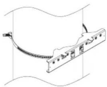
natural_image
Technical line drawing of a mechanical component with a curved cable and mounting holes (no text or symbols)
natural_image
Technical line drawing of a mechanical assembly with mounting brackets and a housing (no text or symbols)-
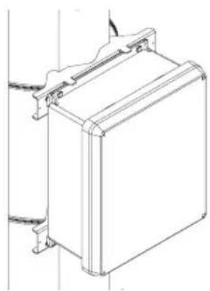
Attach the bottom bracket to the enclosure by inserting bolts through the flange of the enclosure and into the bracket, tightening bolts with a 7/16" hex socket (Fig. 7, pg. 7).
-
Thread the second wormgear quick release strap through the slots on the back of the bottom mounting bracket (Fig. 5, pg. 7).
-
Mount enclosure onto the top bracket by inserting bolts through flange of the enclosure and into the bracket, tightening bolts with a 7/16" hex socket (Fig. 7, pg. 7).
-
Tighten the straps of the bottom bracket down by sliding the open end of the strap through the locking mechanism on the strap, then tighten screw with flat head screwdriver or 5/16" hex socket driver (Fig. 6, pg. 7).
-
Clip excess straps.

natural_image
Technical line drawing of a mechanical assembly with a cable and connector (no text or symbols)Fig. 9
2" to 8"(50.8mm to 203.2mm)
diameter round pole

natural_image
Technical line drawing of a mechanical device with attached cables and components (no text or symbols)Fig. 9a
5" (127mm) square pole
natural_image
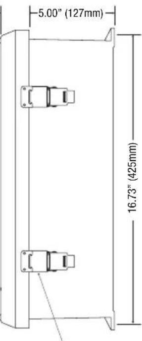
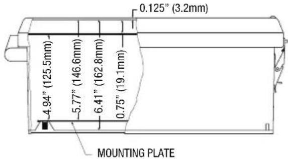
Technical line drawing of a rectangular enclosure or enclosure with mounting brackets and wiring (no text or symbols)NetWay4E1WP/NetWay4E1WPN Mechanical Drawing and Dimensions (H x W x D approx.):
13.31" x 11.31" x 5.59" (338.1mm x 287.3mm x 142mm)
FRONT VIEW
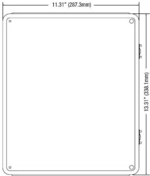
RIGHT SIDE VIEW

FRONT VIEW COVER REMOVED

END VIEW
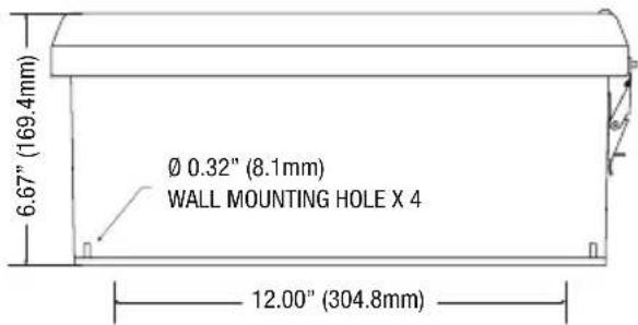
NetWay4E1WPX Mechanical Drawing and Dimensions (H x W x D approx.):
17.53" x 15.3" x 6.67" (445.3mm x 388.6mm x 169.4mm)
1.67" (42.4mm)
316 STAINLESS STEEL PADLOCK LATCH ATTACHED WITH RIVETS. ∅ 0.375 PADLOCK EYE
FRONT VIEW COVER REMOVED

SECTION A-A
END VIEW
NetWay4E1X
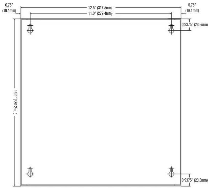
Mechanical Drawing and Dimensions (H x W x D approx.):
13.5" x 13" x 3.25" (342.9mm x 330.2mm x 82.6mm)




Notes:
Notes:
Altronix is not responsible for any typographical errors.
140 58th Street, Brooklyn, New York 11220 USA | phone: 718-567-8181 | fax: 718-567-9056
website: www.altronix.com | e-mail: info@altronix.com | Lifetime Warranty
IINetway4E1 Series E02V
- NetWay4E1WPX
- NetWay4E1X
- NetWay4E1WPN
- NetWay4E1PL
- NetWay4E1B
- Installation Guide
- CE
- Overview:
- Features:
- Agency Listings:
- Input:
- Power Output:
- SFP Ports:
- Ethernet Ports:
- Indicators (LED):
- Mechanical:
- NetWay4E1B:
- NetWay4E1WP, NetWay4E1WPN:
- NetWay4E1WPX:
- NetWay4E1X:
- InstallationInstructions:
- Installation:
- NetWay4E1B/NetWay4E1PL:
- NetWay4E1WPN/NetWay4E1WP/NetWay4E1WPX:
- Power Connection:
- Input/Data Connections:
- Recommended Altronix SFP Modules:
- Recommended Altronix Power Sourcing Equipment:
- Typical Applications:
- Wall Mount Installation
- Pole Mounting Using Optional Pole Mount Kit PMK1 (NetWay4E1WP) or PMK2 (NetWay4E1WPX):
- NetWay4E1WP/NetWay4E1WPN Mechanical Drawing and Dimensions (H x W x D approx.):
- NetWay4E1WPX Mechanical Drawing and Dimensions (H x W x D approx.):
- Mechanical Drawing and Dimensions (H x W x D approx.):
- Notes:
Brand : Altronix
Model : NetWay4E1WP
Category : Network Card/Adapter