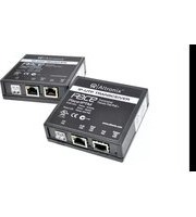
Pace1PRMT - Network Card/Adapter Altronix - Free user manual and instructions
Find the device manual for free Pace1PRMT Altronix in PDF.


| Product Type | Long Range Ethernet Adapter Kit (Receiver and Transceiver) |
| Model | Pace1PRMT (Pace1PRM Receiver + Pace1PTM Transceiver) |
| Dimensions (Receiver & Transceiver) | 3.5" x 3.5" x 1" (88.89 mm x 88.89 mm x 25.4 mm) |
| Weight (Product) | 3.88 oz (0.11 kg) |
| Weight (Shipping) | 6.70 oz (0.19 kg) |
| Input Power (Pace1PRM) | Powered by PoE midspan or endspan; compliant to IEEE 802.3af (15W) and 802.3at (30W) |
| Ethernet Connectivity | RJ45, auto-crossover; 10/100BaseT, half/full duplex, auto negotiation |
| Maximum Distance (CAT5e or higher) | Up to 500 m (1,640 ft) at 100 Mbps |
| Maximum Distance (Single UTP) | Up to 152 m at 100 Mbps |
| PoE Output (Pace1PTM) | Compliant to IEEE 802.3af (15W) and 802.3at (30W) to connected device |
| LED Indicators | Green: PoE ON; Yellow + Green: Link/Activity and 10/100Base-T status |
| Operating Temperature (Pace1PRM) | -20°C to 49°C (-4°F to 120.2°F) |
| Operating Temperature (Pace1PTM) | For 15W: -40°C to 75°C; for 25W: -40°C to 70°C; for 30W: -40°C to 60°C |
| Storage Temperature | -40°C to 75°C (-40°F to 167°F) |
| Humidity | 20 to 85%, non-condensing |
| Safety Compliance | UL/CUL Listed (UL 60950-1), CE approved, C-Tick compliant |
| Indoor Use Only | Designed for installation within protected premises |
| Auto Detection of Non-PoE Devices | Automatically detects and protects legacy non-PoE cameras/devices |
| Application | Extends network link distance up to 700 m (with proper cabling); retrofit IP cameras over analog CCTV wiring |
Frequently Asked Questions - Pace1PRMT Altronix
User questions about Pace1PRMT Altronix
0 question about this device. Answer the ones you know or ask your own.
Ask a new question about this device
Download the instructions for your Network Card/Adapter in PDF format for free! Find your manual Pace1PRMT - Altronix and take your electronic device back in hand. On this page are published all the documents necessary for the use of your device. Pace1PRMT by Altronix.
USER MANUAL Pace1PRMT Altronix
IP and PoE+ Over Extended Distance UTP or CAT5e Pace1PRM Receiver and Pace1PTM Transceiver kit

LISTED
I.T.E. 43KC

Z1409
Overview:
Pace1PRMT is a long range Ethernet adapter kit which transmits data at 100mbps full duplex and power via a single twisted pair (UTP) or Cat5e or higher cable in a PoE(+) compliant format. The Pace1PRM receiver is powered via a PoE midspan such as the Altronix Netway series or by an endspan. The receiver passes the PoE(+) compliant power over the cable to the Pace1PTM transceiver which in turn passes this power to an enabled IP camera/device. These plug and play units facilitate cost effective solutions for IP devices that need to be installed at distances greater than 100m. They also provide a simple way to replace legacy analog products with new IP devices over single twisted pair (UTP) or structured cable.
Features:
Agency Listings:
- UL/CUL Listed for Information Technology Equipment (UL 60950-1).
- CE approved.
• C-Tick compliant.
Input (Pace1PRM):
- Powered by midspan or endspan. PoE compliant to IEEE 802.3af (15W) and PoE+ compliant to IEEE 802.3at (30W).
Ethernet:
- Connectivity: RJ45, auto-crossover.
- Wire type: 4-pair CAT5 or 1 pair UTP structured cable.
• Distance: up to 500m (1,640 ft.). - Speed: 10/100BaseT, half/full duplex, auto negotiation. PoE compliant to IEEE 802.3af (15W) and PoE+ compliant to IEEE 802.3at (30W) delivered to camera by Pace1PTM. Power provided by Pace1PRM to Pace1PTM by PoE protocol.*
- Throughput is rated to pass 100mbps of data at distances up to 500m with proper headend equipment, this supports Megapixel, HD720, HD1080.
CAT5e or higher:
- Distance: up to 500m @ 100mbps (see Maximum Length of Cable Type vs. Camera Power/PoE Class, pg. 4).
UTP (single pair):
- Distance: up to 152m @ 100mbps (see Max. Length of Cable Type vs. Camera Power/PoE Class, pg. 4).
LED Indicators:
- Pace1PRM/Pace1PTM: Green - PoE ON (by respective RJ45 jack).
- Pace1PRM and Pace1PTM (RJ45 jack): Yellow and Green LED IP Link status, 10/100Base-T/active.
Environmental:
- Operating and Storage Temperature: (refer to Technical Specifications chart pg. 2).
• Humidity: 20 to 85%, non-condensing.
Functions:
- Auto detection and protection of legacy non-PoE cameras/devices.
Applications:
- Extend Network link distance in an industrial environment over 700m (see note, pg. 2).
- Retrofit digital IP cameras in an analog CCTV CAT5e wired installations.
- Works with Megapixel, HD720, HD1080 and VGA (SD) cameras (see note, pg. 3).
Mechanical:
- Dimensions (W x L x H approx.): Pace1PRM/Pace1PTM: 3.5" x 3.5" x 1" (88.89mm x 88.89mm x 25.4mm).
InstallationInstructions:
Wiring methods shall be in accordance with the National Electrical Code/NFPA 70/ANSI, and with all local codes and authorities having jurisdiction. Wiring should be UL Listed and/or Recognized wire suitable for the application.
Pace1PTM and Pace1PRM are not intended to be connected to outside plant leads and should be installed indoors within the protected premises. Pace1PRM and Pace1PTM are intended for indoor use only.
1. Pace1PRM installation:
a. Secure unit to desired mounting surface with a proper fastening device utilizing the unit's mounting hole (Fig. 2a, pg. 3). Unit should be mounted in proximity to ethernet switch/network, NVR or video server.
b. Connect structured cable from ethernet midspan or endspan device to RJ45 jack marked [PoE Input] (Fig. 2, pg. 3).
c. CAT5e or higher: Connect CAT5e or higher to connector marked [RJ45 OUT] (Fig. 2, pg. 3). UTP: Connect single UTP to connector marked [UTP OUT] (Fig. 2, pg. 3).
2. Pace1PTM installation:
a. Secure unit to desired mounting surface with a proper fastening device utilizing the case's mounting hole (Fig. 2a, pg. 3). Unit should be mounted in proximity of camera/device.
b. Connect structured cable from IP camera/device to RJ45 jack marked [PoE Out] (Fig. 2, pg. 3).
c. CAT5e or higher: Connect CAT5e or higher to connector marked [RJ45 IN] (Fig. 2, pg. 3).
UTP: Connect UTP to connector marked [UTP IN].
Technical Specifications:
| Parameter Description | |
| Connections RJ45 | for ethernet link or single pair UTP. |
| Input power requirements | Midspan or endspan port connected.PoE compliant to IEEE 802.3af (15W) andPoE+ compliant to IEEE 802.3at (30W) |
| Indicators | Yellow (RJ45 connector): On - Link, Off - No Link, Blinking - Activity.Green (RJ45 connector): On - 100Base-TX, Off - 10Base-T.Green: PoE Active. |
| Environmental Conditions | Operating Ambient Temperature: UL60950-1Pace1PRM:-20°C to 49°C (-4°F to 120.2°F).Pace1PTM: For 15W: -40° to 75°C (-40° to 167°F)For 25W: -40° to 70°C (-40° to 158°F)For 30W: -40° to 60°C (-40° to 140°F)Relative humidity: 20 to 85%, non-condensing.Storage Temperature: -40° to 75°C (-40° to 167°F).Operating Altitude: -304.8 to 2000m (-1000 to 6,561.679 ft.). |
| Regulatory Compliance | UL/CUL Listed for Information Technology Equipment (UL 60950-1).CE approved. C-Tick compliant. |
| Weights (approx.) | Product: 3.88 oz. (0.11 kg.), Shipping: 6.70 oz. (0.19 kg.) |
Fig. 1
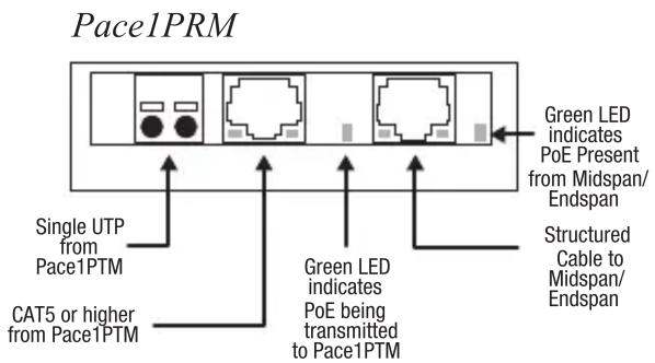
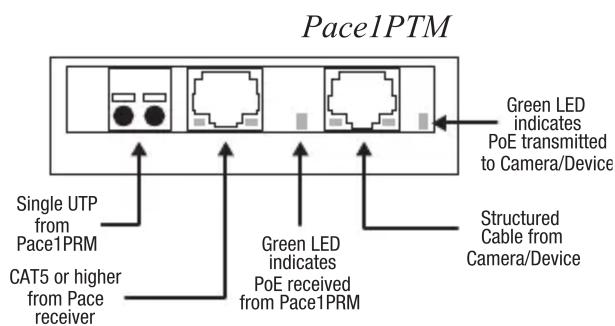
*Note: Caution, once PoE connection is established between Pace1PRM and Pace1PTM, disconnection from Pace1PTM will not disable the PoE output voltage on the Pace1PRM, although the Pace1PTM can be reconnected, caution should be taken not to connect the CAT5e or single UTP wiring from Pace1PRM to any non-PoE device.
Single PoE Camera Connection Utilizing Pace1PRM and Pace1PTM:
Fig. 2 Fig. 2a

flowchart
graph TD
    A["Pace1PRM"] --> B["Altronix®"]
    B --> C["IP-UTP Receiver"]
    C --> D["RJ45 LEDs Yellow - Activity"]
    C --> E["Green - Speed"]
    C --> F["Green LED Power and PoE"]
    G["Pace1PTM"] --> H["Altronix®"]
    H --> I["RJ45 LEDs Yellow - Activity"]
    H --> J["Green - Speed"]
    H --> K["Green LED Power and PoE"]
    L["PoE Camera"] --> M["Output"]
    M --> N["Input"]
    N --> O["Output"]
    O --> P["Input"]
    P --> Q["Output"]
    Q --> R["Input"]
    R --> S["Output"]
    S --> T["Input"]
    T --> U["Output"]
    U --> V["Input"]
    V --> W["Output"]
    W --> X["Input"]
    X --> Y["Output"]
    Y --> Z["Input"]
    Z --> AA["Output"]
    AA --> AB["Input"]
    AB --> AC["Output"]
    AC --> AD["Input"]
    AD --> AE["Output"]
    AE --> AF["Input"]
    AF --> AG["Output"]
    AG --> AH["Input"]
    AH --> AI["Output"]
    AI --> AJ["Input"]
    AJ --> AK["Output"]
    AK --> AL["Input"]
    AL --> AM["Output"]
    AM --> AN["Input"]
    AN --> AO["Output"]
    AO --> AP["Input"]
    AP --> AQ["Output"]
    AQ --> AR["Input"]
    AR --> AS["Output"]
    AS --> AT["Input"]
    AT --> AU["Output"]
    AU --> AV["Input"]
    AV --> AW["Output"]
    AW --> AX["Input"]
    AX --> AY["Output"]
    AY --> AZ["Input"]
    AZ --> BA["Output"]
    BA --> BB["Input"]
    BB --> BC["Output"]
    BC --> BD["Input"]
    BD --> BE["Output"]
    BE --> BF["Input"]
    BF --> BG["Output"]
    BG --> BH["Input"]
    BH --> BI["Output"]
    BI --> BJ["Input"]
    BJ --> BK["Output"]
    BK --> BL["Input"]
    BL --> BM["Output"]
    BM --> BN["Input"]
    BN --> BO["Output"]
    BO --> BP["Input"]
    BP --> BQ["Output"]
    BQ --> BR["Input"]
    BR --> BS["Output"]
    BS --> BT["Input"]
    BT --> BU["Output"]
    BU --> BV["Input"]
    BV --> BW["Output"]
    BW --> BX["Input"]
    BX --> BY["Output"]
    BY --> BZ["Input"]
    BZ --> CA["Output"]
    CA --> CB["Input"]
    CB --> CC["Output"]
    CC --> CD["Input"]
    CD --> CE["Output"]
    CE --> CF["Input"]
    CF --> CG["Output"]
    CG --> CH["Input"]
    CH --> CI["Output"]
    CI --> CJ["Input"]
    CJ --> CK["Output"]
    CK --> CL["Input"]
    CL --> CM["Output"]
    CM --> CN["Input"]
    CN --> CO["Output"]
    CO --> CP["Input"]
    CP --> CQ["Output"]
    CQ --> CR["Input"]
    CR --> CS["Output"]
    CS --> CT["Input"]
    CT --> CU["Output"]
    CU --> CV["Input"]
    CV --> CW["Output"]
    CW --> CX["Input"]
    CX --> CY["Output"]
    CY --> CZ["Input"]
    CZ --> DA["Output"]
    DA --> DB["Input"]
    DB --> DC["Output"]
    DC --> DE["Input"]
    DE --> DF["Output"]
    DF --> DG["Input"]
    DG --> DH["Output"]
    DH --> DI["Input"]
    DI --> DJ["Output"]
    DJ --> DK["Input"]
    DK --> DL["Output"]
    DL --> DM["Input"]
    DM --> DN["Output"]
    DN --> DO
Multiple PoE Cameras Connection:
Fig. 3

tree
| Powered Switch or NetWay MidSpan | Pace1PRM | PoE+ over CAT5e up to 500m (1,640 ft.) max. or Single UTP up to 152.4m (500 ft.) max. | Pace1PTM | PoE compliant 100m (328 ft.) max. | PoE Camera | |---|---|---|---|---|---| | Top Node | 100m (328 ft.) max. | PoE+ over CAT5e up to 500m (1,640 ft.) max. or Single UTP up to 152.4m (500 ft.) max. | | | | | Middle Node | 100m (328 ft.) max. | PoE+ over CAT5e up to 500m (1,640 ft.) max. or Single UTP up to 152.4m (500 ft.) max. | Pace1PTM | PoE compliant 100m (328 ft.) max. | PoE Camera | | Bottom Node | 100m (328 ft.) max. | PoE+ over CAT5e up to 500m (1,640 ft.) max. or Single UTP up to 152.4m (500 ft.) max. | Pace1PTM | PoE compliant 100m (328 ft.) max. | PoE Camera | Legend: Structured Cable or Single UTPMaximum Length of Cable Type vs. Camera Power/PoE Class:
| Cable Type | Total Power Consumption | Max. Data Distance | Max. Power Distance |
| CAT5e | 15W | 500m | 846m |
| 30W 423m |
| Cable Type | Total Power Consumption | Max. Data Distance | Max. Power Distance |
| Single UTP (23AWG) | 15W | 152m | 266m |
| 30W 133m |
Note: Calculations based on 56VDC starting voltage from power source and accounts for a 10VDC voltage drop. IEEE standards voltage range requirement for powered devices are:
PoE (15W) - 37VDC to 57VDC
PoE+ (30W) - 44VDC to 57VDC .

- Overview:
- Features:
- Agency Listings:
- Input (Pace1PRM):
- Ethernet:
- CAT5e or higher:
- UTP (single pair):
- LED Indicators:
- Environmental:
- Functions:
- Applications:
- Mechanical:
- InstallationInstructions:
- Pace1PRM installation:
- Pace1PTM installation:
- Single PoE Camera Connection Utilizing Pace1PRM and Pace1PTM:
- Multiple PoE Cameras Connection:
Brand : Altronix
Model : Pace1PRMT
Category : Network Card/Adapter