DC-S6281HX - Security Camera IDIS - Free user manual and instructions
Find the device manual for free DC-S6281HX IDIS in PDF.


| Product Type | Network Security Camera |
| Model | DC-S6281HX |
| Image Sensor | 1/2.8" Progressive Scan CMOS |
| Maximum Resolution | 1920 x 1080 (2 Megapixel) |
| Lens | 2.8 - 12mm Varifocal Motorized Lens |
| IR Range | Up to 30 meters |
| Day/Night Function | Yes, with IR Cut Filter |
| Video Compression | H.265 / H.264 / MJPEG |
| Power Supply | PoE (IEEE 802.3af) or 12V DC |
| Power Consumption | Max 8W |
| Dimensions (W x H x D) | 70 x 170 x 70 mm |
| Weight | Approx. 500 g |
| Ingress Protection | IP66 |
| Operating Temperature | -30°C to 60°C |
| Mounting | Wall or Ceiling Mount |
| Main Features | Motion Detection, Tamper Alarm, Privacy Mask, Micro SD Slot |
| Network Interface | 10/100 Mbps Ethernet (RJ45) |
| Supported Protocols | TCP/IP, HTTP, RTSP, ONVIF |
| Maintenance | Clean lens with dry cloth; avoid solvents |
| Security | Password protection, AES encryption |
| Spare Parts / Repairability | Contact IDIS support for replacements; not user-serviceable |
| General Information | Indoor/Outdoor use, compatible with IDIS NVR |
Frequently Asked Questions - DC-S6281HX IDIS
User questions about DC-S6281HX IDIS
0 question about this device. Answer the ones you know or ask your own.
Ask a new question about this device
Download the instructions for your Security Camera in PDF format for free! Find your manual DC-S6281HX - IDIS and take your electronic device back in hand. On this page are published all the documents necessary for the use of your device. DC-S6281HX by IDIS.
USER MANUAL DC-S6281HX IDIS
Before reading this manual
This is a basic installation manual for use of an IDIS network camera. Users who are using this product for the first time, as well as users with experience using comparable products, must read this operation manual carefully before use and heed to the warnings and precautions contained herein while using the product. Safety warnings and precautions contained in this operation manual are intended to promote proper use of the product and thereby prevent accidents and property damage and must be followed at all times. Once you have read this operation manual, keep it at an easily accessible location for future reference.

- The manufacturer will not be held responsible for any product damage resulting from the use of unauthorized parts and accessories or from the user's failure to comply with the instructions contained in this manual.
- The information in this document is believed to be accurate as of the date of publication even though explanation about some functions may not be incorporated. The manufacturer is not responsible for any problems resulting from the use thereof. The information contained herein is subject to change without notice. Revisions or new editions to this publication may be issued to incorporate such changes.
- It is recommended that first-time users of this network camera and individuals who are not familiar with its use seek technical assistance from their retailer regarding product installation and use.
- If you need to disassemble the product for functionality expansion or repair purposes, you must contact your retailer and seek professional assistance.
- Both retailers and users should be aware that this product has been certified as being electromagnetically compatible for commercial use. If you have sold or purchased this product unintentionally, please replace with a consumer version.
Safety Symbols
| Symbol | Type Description | |
 | Warning | An important instruction or set of important instructions that can lead to severe injury or even death if not followed. |
 | Caution | An instruction or set of instruction that can lead to personal injury and/or property damage if not followed. |
In-Text
| Symbol | Type Description |
 | Caution Important information concerning a specific function. |
| [TSTK] | Note Useful information concerning a specific function. |
Safety Precautions
WARNING
RISK OF ELECTRIC SHOCK
DO NOT OPEN
WARNING: TO REDUCE THE RISK OF ELECTRIC SHOCK,
DO NOT REMOVE COVER (OR BACK).
NO USER-SERVICEABLE PARTS INSIDE.
REFER SERVICING TO QUALIFIED SERVICE PERSONNEL.
Important Safeguards
1. Read Instructions
All the safety and operating instructions should be read before the appliance is operated.
2. Retain Instructions
The safety and operating instructions should be retained for future reference.
3. Cleaning
Unplug this equipment from the wall outlet before cleaning it. Do not use liquid aerosol cleaners. Use a damp soft cloth for cleaning.
4. Attachments
Never add any attachments and/or equipment without the approval of the manufacturer as such additions may result in the risk of fire, electric shock or other personal injury.
5. Water and/or Moisture
Do not use this equipment near water or in contact with water.
6. Placing and Accessories
Do not place this equipment on an wall or ceiling that is not strong enough to sustain the camera. The equipment may fall, causing serious injury to a child or adult, and serious damage to the equipment. Wall or shelf mounting should follow the manufacturer's instructions, and should use a mounting kit approved by the manufacturer.

This equipment and cart combination should be moved with care.
Quick stops, excessive force, and uneven surfaces may cause the equipment and cart combination to overturn.
Do not place this equipment in an enclosed space. Sufficient ventilation is required to prevent an increase in ambient temperature which can cause malfunction or the risk of fire.
7. Power Sources
This equipment should be operated only from the type of power source indicated on the marking label. If you are not sure of the type of power, please consult your equipment dealer or local power company.
You may want to install a UPS (Uninterruptible Power Supply) system for safe operation in order to prevent damage caused by an unexpected power stoppage. Any questions concerning UPS, consult your UPS retailer.
8. Power Cord
Operator or installer must remove power and TNT connections before handling the equipment.
9. Lightning
For added protection for this equipment during a lightning storm, or when it is left unattended and unused for long periods of time, unplug it from the wall outlet and disconnect the antenna or cable system. This will prevent damage to the equipment due to lightning and power-line surges. If thunder or lightning is common where the equipment is installed, use a surge protection device.
10. Overloading
Do not overload wall outlets and extension cords as this can result in the risk of fire or electric shock.
11. Objects and Liquids
Never push objects of any kind through openings of this equipment as they may touch dangerous voltage points or short out parts that could result in a fire or electric shock. Never spill liquid of any kind on the equipment.
12. Servicing
Do not attempt to service this equipment yourself. Refer all servicing to qualified service personnel.
13. Damage requiring Service
Unplug this equipment from the wall outlet and refer servicing to qualified service personnel under the following conditions:
A. When the power-supply cord or the plug has been damaged.
B. If liquid is spilled, or objects have hit the equipment.
C. If the equipment has been exposed to rain or water.
D. If the equipment does not operate normally by following the operating instructions, adjust only those controls that are covered by the operating instructions as an improper adjustment of other controls may result in damage and will often require extensive work by a qualified technician to restore the equipment to its normal operation.
E. If the equipment has been dropped, or the cabinet damaged.
F. When the equipment exhibits a distinct change in performance — this indicates a need for service.
14. Replacement Parts
When replacement parts are required, be sure the service technician has used replacement parts specified by the manufacturer or that have the same characteristics as the original part. Unauthorized substitutions may result in fire, electric shock or other hazards.
15. Safety Check
Upon completion of any service or repairs to this equipment, ask the service technician to perform safety checks to determine that the equipment is in proper operating condition.
16. Field Installation
This installation should be made by a qualified service person and should conform to all local codes.
17. Correct Batteries
Warning: Risk of explosion if battery is replaced by an incorrect type. Replace only with the same or equivalent type. Dispose of used batteries according to the instructions. The battery shall not be exposed to excessive heat such as sunshine, fire or the like.
A manufacturer's maximum recommended ambient temperature (Tmra) for the equipment must be specified so that the customer and installer may determine a suitable maximum operating environment for the equipment.
FCC Compliance Statement
THIS EQUIPMENT HAS BEEN TESTED AND FOUND TO COMPLY WITH THE LIMITS FOR A CLASS A DIGITAL DEVICE, PURSUANT TO PART 15 OF THE FCC RULES. THESE LIMITS ARE DESIGNED TO PROVIDE REASONABLE PROTECTION AGAINST HARMFUL INTERFERENCE WHEN THE EQUIPMENT IS OPERATED IN A COMMERCIAL ENVIRONMENT. THIS EQUIPMENT GENERATES, USES, AND CAN RADIATE RADIO FREQUENCY ENERGY AND IF NOT INSTALLED AND USED IN ACCORDANCE WITH THE INSTRUCTION MANUAL, MAY CAUSE HARMFUL INTERFERENCE TO RADIO COMMUNICATIONS. OPERATION OF THIS EQUIPMENT IN A RESIDENTIAL AREA IS LIKELY TO CAUSE HARMFUL INTERFERENCE, IN WHICH CASE USERS WILL BE REQUIRED TO CORRECT THE INTERFERENCE AT THEIR OWN EXPENSE.
WARNING: CHANGES OR MODIFICATIONS NOT EXPRESSLY APPROVED BY THE PARTY RESPONSIBLE FOR COMPLIANCE COULD VOID THE USER'S AUTHORITY TO OPERATE THE EQUIPMENT. THIS CLASS OF DIGITAL APPARATUS MEETS ALL REQUIREMENTS OF THE CANADIAN INTERFERENCE CAUSING EQUIPMENT REGULATIONS.
WEEE (Waste Electrical & Electronic Equipment)
Correct Disposal of This Product
(Applicable in the European Union and other European countries with separate collection systems)
This marking shown on the product or its literature, indicates that it should not be disposed with other household wastes at the end of its working life. To prevent possible harm to the environment or human health from uncontrolled waste disposal, please separate this from other types of wastes and recycle it responsibly to promote the sustainable reuse of material resources.
Household users should contact either the retailer where they purchased this product, or their local government office, for details of where and how they can take this item for environmentally safe recycling.
Business users should contact their supplier and check the terms and conditions of the purchase contract. This product should not be mixed with other commercial wastes for disposal.
Copyright
© 2022 IDIS Co., Ltd.
IDIS Co., Ltd. reserves all rights concerning this operation manual.
Use or duplication of this operation manual in part or whole without the prior consent of IDIS Co., Ltd. is strictly prohibited.
Contents of this operation manual are subject to change without prior notice for reasons such as functionality enhancements.
Registered Trademarks
IDIS is a registered trademark of IDIS Co., Ltd.
Other company and product names are registered trademarks of their respective owners.
The software included in this product contains some Open Sources. You may obtain the corresponding source code which we have to distribute according to the license policy. For more information, refer to System > General page. This product includes software developed by the University of California, Berkeley and its contributors, and software developed by the OpenSSL Project for use in the OpenSSL Toolkit (http://www.openssl.org/). Also, this product includes cryptographic software written by Eric Young (eay@cryptsoft.com).
Covered by one or more claims of the patents listed at patentlist.accessadvance.com.
1
Part 1 – Introduction......6
Product Features 6
Accessories....7
Overview 8
Indoor and Outdoor....8
Flushed....10
Cable 11
Factory Reset 12
Installation....12
Indoor 12
Outdoor 13
Flushed....14
Dimensions....15
2
Part 2 - Camera Connection ....16
With DirectIP® NVR-based Layout ....16
With non DirectIP® NVR-based Layout....17
3
Part 3 - Appendix....18
Troubleshooting ....18
Specifications....19
Product Features
DC-S6281FX / DC-S6281HX are IP-based network cameras that compress and transmit video over ethernet.
You can use the IDIS Discovery program to change network camera settings or the IDIS Solution Suite Compact program to manage multiple network cameras. In addition, the embedded web server (IDIS Web) lets you remotely view live video or scan recorded video using a web browser. In addition, you can use the IDIS Solution Suite Compact to manage network cameras and view/record video.

In this operation manual, the term Remote System refers to the computer on which the remote program (IDIS Solution Suite Compact or IDIS Web) is running.
- Supports DirectIP mode working with a DirectIP® NVR that allows users to simply set up all required configurations without a PC
• Supports ONVIF protocol (v2.4.0, Profile S) - Multi-streaming for high-resolution and high-quality video monitoring and simultaneous recording in real-time as well as flexible configurations for those
• Supports H.265, H.264 video compression, and M-JPEG still image compression algorithms
• Supports 4-stage video compression rate and multiple compression resolutions - Two-way audio communication support for remote audio dialog
- Video stream buffering to counter pre-/post-event buffering and network delays for improved network recording reliability
-
Remote monitoring via web browser or remote software
• Automatic web casting code (HTML) generation -
Up to 10 simultaneous remote monitoring connections
- IP filtering, HTTPS, SSL, IEEE 802.1X, and configurable user authority levels for greater security
• Network bandwidth limitation and MAT features for more efficient use of network bandwidth - Easy network access via UPnP (Universal Plug and Play) function and embedded mDNS (Multicast DNS) protocol
- Wide dynamic range compensation (Digital WDR) for improved video quality in high-contrast situations
- Slow shutter support for improved low-lighting video capture performance
- Day & Night feature (built-in IR cut filter changer)
- Quick and easy firmware upgrade over the network
- Redundant firmware and auto recovery features for improved system stability
• Network-based integrated management of multiple network cameras - Multiple event detection modes: Alarm-in, motion detection, trip zone, audio detection, and tampering
- Backup storage on a microSD memory card as a safeguard against data loss during network interruptions
• Supports 24 VAC and PoE (Power over Ethernet)
• Supports zoom function using an AF zoom lens - Pan/Tilt control with a micro stepping motor
- Features a built-in heater for continued use in sub-zero temperature conditions (DC-S6281HX model only)
- IP67-level for waterproof and dustproof features (DC-S6281HX model only)

Remote monitoring and recording via multistreaming are available using the IDIS Solution Suite Compact program. For more information on using IDIS Solution Suite Compact, refer to its operation manual.

There is a limit to the number of users allowed to connect remotely via the Internet at the same time.
Accessories
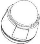
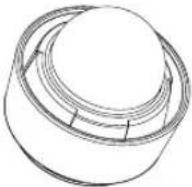
Upon purchasing the product, check inside the box to make sure all the following accessories are included. External appearances and colors of the accessories may vary depending on the model.
  Indoor Outdoor Indoor Outdoor | 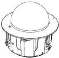 | |
| DC-S6281HX DC-S6281FX | ||
| Network Camera | ||
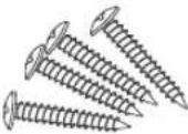 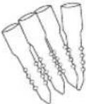 |  | |
| Screws and Anchors (4 ea.) DC-S6281HX model only | Quick Guide | |
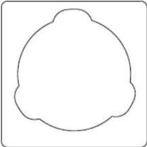 | 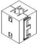 | |
| Guide Pattern DC-S6281FX model only | Ferrite Core | |
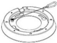 | 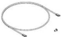 | |
| Indoor Bracket, Screw DC-S6281HX model only | Grounding Cable, Screw DC-S6281HX model only | |
Overview

Product color and design may vary depending on the model.
Indoor and Outdoor
Body
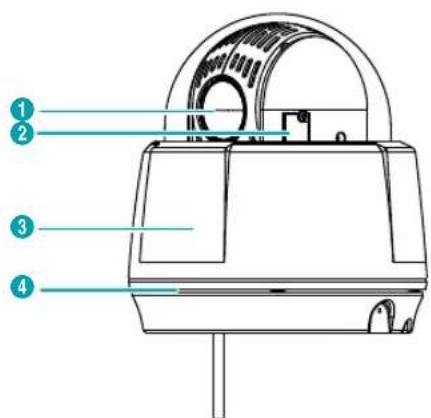
| 1 | Lens |
| 2 | SD Memory Card Slot |
| 3 | Dome Cover |
| 4 | Waterproof Sealing (black rubber) |
- Lens
AF zoom lens is mounted.
• SD Memory Card Slot
Used to insert a microSD memory card into the camera. (An SLC (Single Level Cell) or MLC (Multi Level Cell) card by SanDisk or Transcend is recommended) Remove the dome cover in order to remove or insert the SD memory card. Make sure that the waterproof sealing is joined properly when reconnecting the dome cover; otherwise, the IP67 level is not guaranteed.

• To remove/insert the SD memory card or perform the factory reset, make sure that the waterproof sealing is screwed to the dome cover tightly when reconnecting the dome cover. Otherwise, the IP67 level is not guaranteed. For more information, contact your product retailer.
- Do not remove the SD memory card while the system is in operation. Removing the card while the system is in operation can cause the system to malfunction and/or corrupt data stored on the SD memory card.
- An SD memory card is a consumable product with a finite service life. Prolonged use will damage the card's memory sectors and result in data loss or memory card failure. Test the SD memory card regularly and replace it whenever necessary.
• Dome Cover
Protects the inner parts of camera.
- Waterproof Sealing
Resists the ingress of water.
Body – Bottom Side View
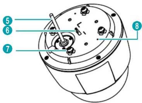
| 5 | Cable |
| 6 | Safety Wire Ring |
| 7 | Install Screw |
| 8 | M3 Screw Hole |
• Cable
Refer to the Cable.
- Safety Wire Ring
Secures the body to the bracket or the bracket to the body. Prevents the body or bracket from falling on to the floor when detached from the body and bracket. ^h (frame ground) is marked beside the safety wire screw hole of the indoor bracket. When fastening the camera body to the indoor bracket, ground the camera by using the grounding clip provided with the camera. It is recommended that you use the camera after grounding it.
• Install Screw
When installing an indoor camera, it secures the body to the indoor bracket.
• M3 Screw Hole
When installing an outdoor camera, use the provided M3 screws to secure the sun shield on to the camera body. m (frame ground) is marked beside the M3 screw hole of the camera body. When fastening the camera body to the indoor bracket, ground the camera by using the grounding clip provided with the camera. It is recommended that you use the camera after grounding it
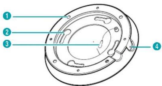
Indoor Bracket
Outdoor Bracket
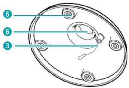

The outdoor bracket is purchased separately. Ask your dealer or distributor about purchasing it.
| 1 | Wall/Ceiling Installation Hole |
| 2 | Install Screw Hole |
| 3 | Safety Wire |
| 4 | M4 Screw Hole |
| 5 | M5 Screw Hole |
| 6 | Pipe Hole |
• Wall/Ceiling Installation Hole
Used to screw the camera in place on a wall or a ceiling.
• Install Screw Hole
When installing an indoor camera, it secures the body to the indoor bracket.
• Safety Wire
Secures the body to the bracket or the bracket to the body. Prevents the body or bracket from falling on to the floor when detached from the body or bracket.
• M4 Screw Hole
When installing an indoor camera, it secures the body to the indoor bracket.
• M5 Screw Hole
When installing an outdoor camera, it secures the sun shield to the outdoor bracket.
- Pipe Hole
When installing an outdoor camera, it secures the pipe, which the cable assembly goes through, to the outdoor bracket.
Part 1 - Introduction
Outdoor Sun Shield
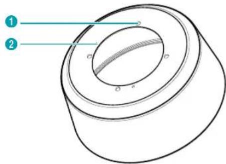

The outdoor sun shield is purchased separately. Ask your dealer or distributor about purchasing it.
| 1 | M5 Screw Hole |
| 2 | M3 Screw Hole |
• M5 Screw Hole
When installing an outdoor camera, it secures the sun shield to the outdoor bracket.
• M3 Screw Hole
When installing an outdoor camera, use the provided sun shield screws to secure the sun shield on to the camera body.
Flushed
Housing
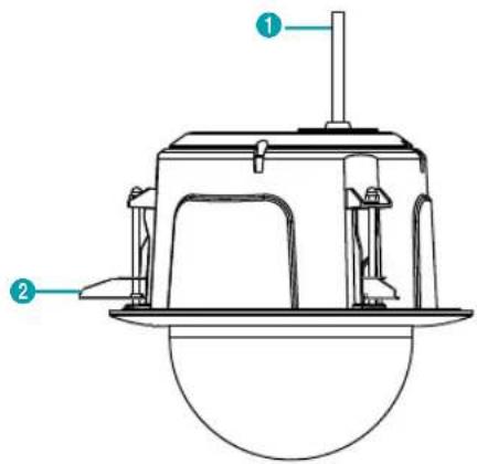
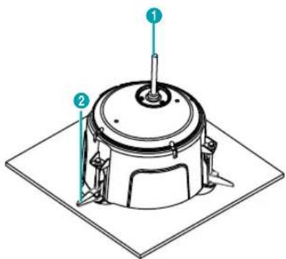
| 1 | Multi Cable |
| 2 | Clamp |
- Multi Cable
Connect the power, device, and network connectors.
- Clamp
Secures the camera to the ceiling.
Cable
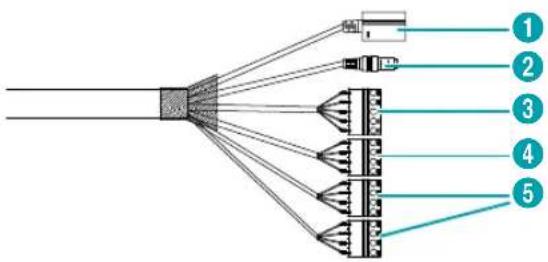
| 1 | Network Port |
| 2 | Power |
| 3 | Audio In/Out |
| 4 | Alarm Out |
| 5 | Alarm In |
• Network Port
Connect a network cable with an RJ-45 connector to this port. If using a PoE switch, you can supply power to the camera using an ethernet cable. For more information on PoE switch use, refer to the switch manufacturer's operation manual. You can configure, manage, and upgrade this camera and monitor its images from a remote computer over the network. For more information on network connection setup, refer to the IDIS Discovery operation manual.
• Power
Connect the 24VAC power.
- Audio In/Out
- L_I: Connect an audio source to this port. (line in)
- L_O: Connect an amplifier to this port (line out). This device does not feature a built-in audio amplifier unit and therefore requires the user to purchase a separate speaker system with a built-in amplifier.
- Alarm In/Out
- ALI:Connect an alarm-in device to this port. (Mechanism: Choose between an NC (Normally Closed) type or an NO (Normally Open) type) → Connect a mechanical or electrical switch to the alarm in port and the GND (ground) connector. Alarm in range is 0V to 5V. In order to detect alarm input from an electrical switch, the signal must be higher than 4.3V from an NC switch or less than 0.3V from an NO switch and must last for longer than 0.5 seconds.
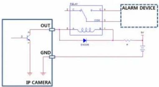
- ALO: It is the BJT (Bipolar Junction Transistor) -open collector output. If the voltage and current exceed the specification limit (max. load: 30mA, max. voltage: 5VDC), the product could be damaged. When connecting the device which exceeds the specification limit, refer to the picture (circuit) below.

If used with an external inductive load(e.g. relay), a diode must be connected in parallel with the load for protection. Otherwise, the product could be damaged.

- Check your local laws and regulations on making video or audio recordings. The user will be held liable for any violation of the law.
- When switching over from 24VAC to PoE as the power source, the system will be rebooted once the power adapter is disconnected.
- Organize the power cable so that it will not cause people to trip over or become damaged from chairs, cabinets, desks, and other objects in the vicinity. Do not run the power cable underneath carpet or a rug or plug the cable into a power outlet shared by a number of other devices.
- The network connector is not designed to be connected directly with cable or wire intended for outdoor use.
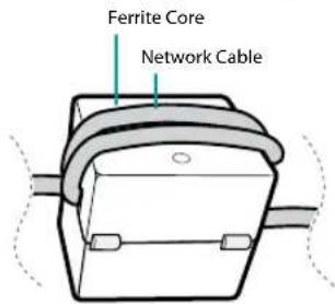
- Wrap the camera-end of the network cable twice around the provided ferrite core for EMC (Electromagnetic Compatibility). If not, you may experience video stuttering.
Part 1 - Introduction
Factory Reset
Only use the factory reset switch to restore the camera to its factory default settings.

The factory reset switch is inside of the camera. Ask your dealer or distributor for details.

A factory reset will clear all camera settings configured by the user.
1 Shut off the power supply, separate the dome cover. Insert a straight pin into the switch hole, and press down on the reset switch.
2 Hold the switch down and reconnect the power adapter.
3 After connecting the power adapter, wait 5 seconds and then take out hands from the switch.
4 The device will go through the resetting process and reboot. All camera settings will be restored to their factory defaults after the reboot.
5 Reconnect the dome cover.
It's also possible to do a factory reset by pressing and releasing the reset switch while the camera is turned on or using the IDIS Discovery program from a remote location. A factory reset will reboot the system. For more information on factory reset, refer to the IDIS Discovery operation manual.

Make sure that the waterproof sealing is joined properly when reconnecting the dome cover; otherwise, the IP66 level is not guaranteed.
Installation
Installation of this product does not require the use of special tools.
For more information on other devices comprising the overall system, refer to their respective installation manuals.

Product color and design may vary depending on the model.

- Check the wall or ceiling to see if it needs to be reinforced. The camera may fall off if the wall or ceiling is not strong enough to support its weight.
• Install the camera in a shaded area. If the camera is installed in direct sunlight, it may affect adversely.
Indoor
natural_image
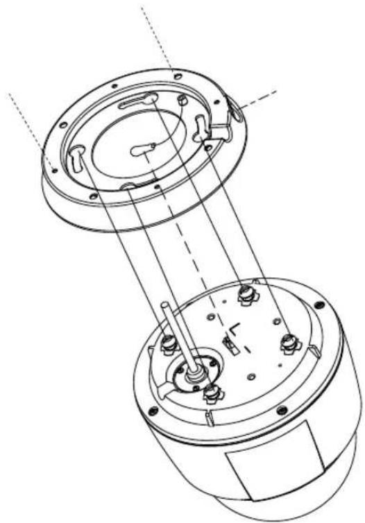
Technical line drawing of a mechanical assembly with two circular components and internal components (no text or symbols)1 Screw the indoor bracket to the wall or ceiling by using the wall/ceiling mounting screws provided with the camera.
2 Make a cable hole in the wall or ceiling.
3 Hook the safety wire of the bracket on the safety wire ring of the camera body.
4 Connect external devices, the network cable, and the power adapter.
5 Connect the camera body to the indoor bracket. Fix the install screws of the camera body up to the install screw holes of the bracket, and then turn the camera body by 25° in the clockwise direction.
6 Fasten the camera body to the bracket by tightening the M4 screw provided with the camera to the to the M4 screw hole of the bracket.
7 Supply the power.
Outdoor
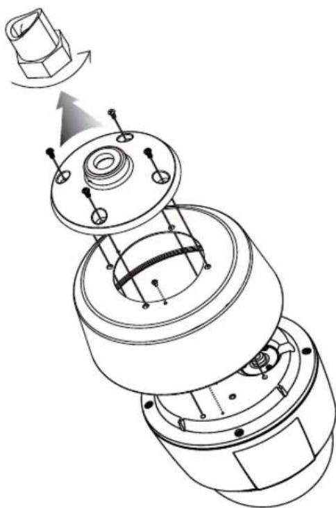
In case that a universal nut is attached to a pipe
Connect the sun shield and outdoor bracket first, then connect it to the pipe as follows:
natural_image
Technical line drawing of a mechanical assembly with no visible text or symbols1 Remove the install screw from the camera body.
2 Screw the sun shield to the camera body by using the M3 screws provided with the sun shield.
3 Hook the safety wire of the outdoor bracket on the safety wire ring of the camera body.
4 Use the M5 screws provided with the sun shield to secure the outdoor bracket on to the sun shield.
5 Connect the cable from the camera to the pipe.
6 Turn the universal nut to connect the camera to the pipe.
7 Connect external devices, the network cable, and the power adapter.
8 Supply the power.
Part 1 - Introduction
In case that a universal nut is not attached to a pipe
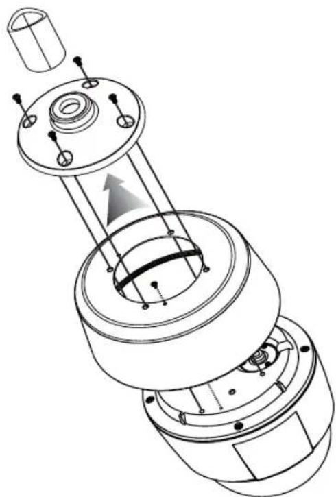
Connect the sun shield to the outdoor bracket as follows:
natural_image
Technical line drawing of a mechanical assembly with internal components and mounting holes (no text or symbols)1 Remove the install screw from the camera body.
2 Screw the sun shield to the camera body by using the M3 screws provided with the sun shield.
3 Assemble the outdoor bracket to the pipe by turning the outdoor bracket.
4 Hook the safety wire of the sun shield on the safety wire ring of the camera body.
5 Connect the cable from the camera to the pipe.
6 Use the provided M5 screws to screw the sun shield to the outdoor bracket.
7 Connect external devices, the network cable, and the power adapter.
8 Supply the power.
Flushed
natural_image
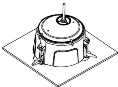
Technical line drawing of a mechanical component with mounting brackets and a central hub (no text or symbols)The camera is mounted in the housing.
1 Refer to the installation guide pattern provided with the product to drill a hole for flushing the camera in the ceiling tile.

The ceiling tile cannot be thicker than 1.18" (30mm).
2 Connect external devices, the network cable, and the power adapter.
3 Insert the housing into the ceiling and turn the screws of three clamps clockwise. The clamps are laid over the ceiling tile and the housing is held in the ceiling.
4 Connect the housing dome cover to the housing can and turn it clockwise to secure the dome cover to the housing.
5 Supply the power.
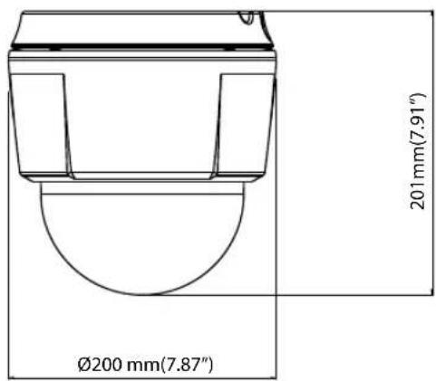
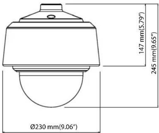
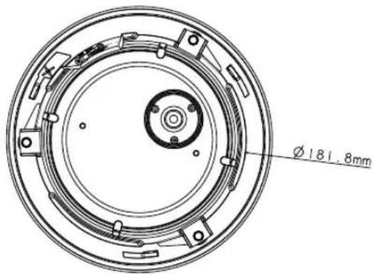
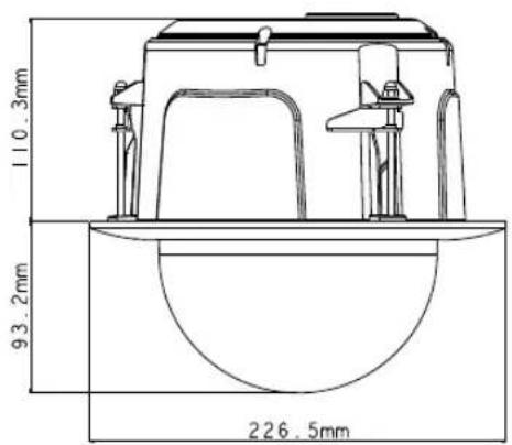
Dimensions
Indoor
DC-S6281HX model
Outdoor
DC-S6281HX model
Flushed
DC-S6281FX model
Part 2 - Camera Connection
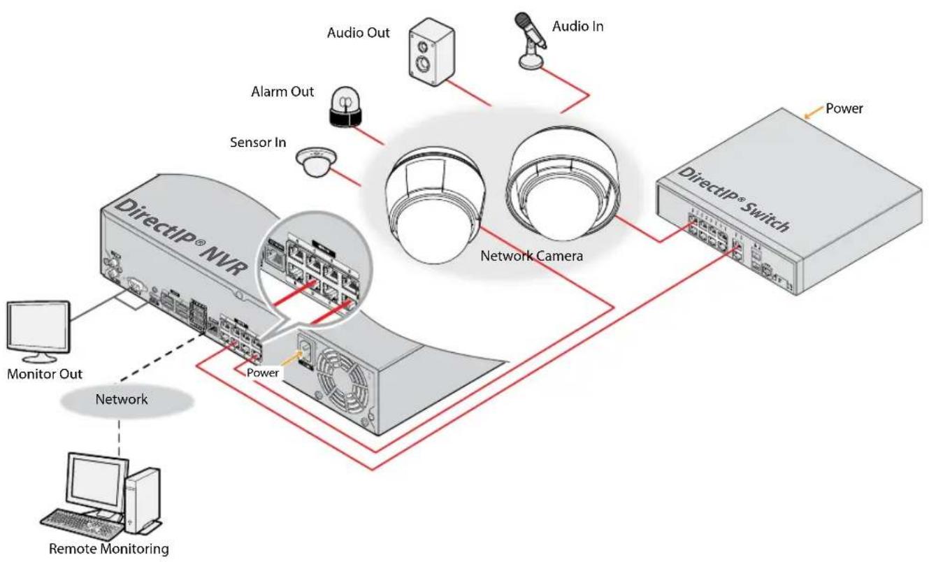
Use the camera by connecting to DirectIP® NVR or non DirectIP® NVR, VMS such as IDIS Solution Suite Compact.
With DirectIP® NVR-based Layout
flowchart
graph TD
    A["Monitor Out"] --> B["Network"]
    C["Remote Monitoring"] --> B
    D["DirectIP® NVR"] --> E["Power"]
    F["Network Camera"] --> G["Power"]
    H["Switch"] --> I["Power"]
    J["Audio In"] --> K["Audio Out"]
    L["Sensor In"] --> M["Alarm Out"]
    style A fill:#f9f,stroke:#333
    style C fill:#f9f,stroke:#333
    style D fill:#ccf,stroke:#333
    style F fill:#ccf,stroke:#333
    style H fill:#ccf,stroke:#333
    style I fill:#ccf,stroke:#333
    style J fill:#ccf,stroke:#333
    style K fill:#ccf,stroke:#333
    style L fill:#ccf,stroke:#333
    style M fill:#ccf,stroke:#333
    style N fill:#ccf,stroke:#333
DirectIP® NVR makes it easy to use cameras without extra network configurations.
Each camera can be controlled via the DirectIP® NVR setup menu, without any PC.
For detailed camera settings, please see the camera setting pages of DirectIP® NVR manual.
For users using the camera with DirectIP® NVR connection, do not need to consider contents in the camera operation manual.
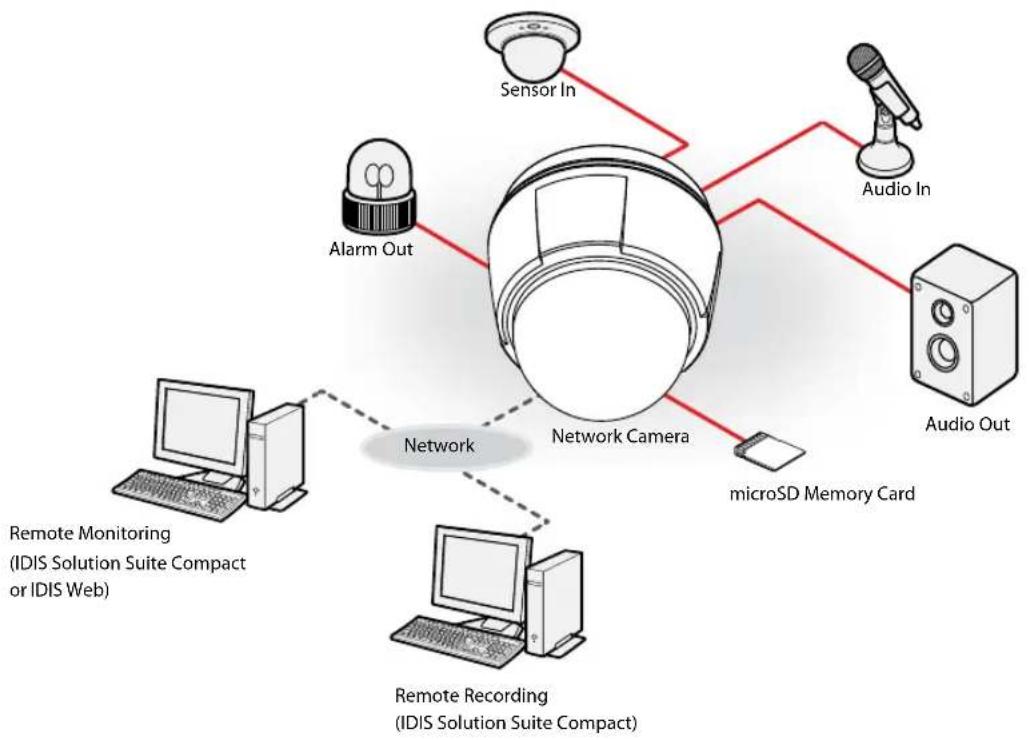
With non DirectIP® NVR-based Layout
flowchart
graph TD
    A["Network Camera"] --> B["Sensor In"]
    A --> C["Alarm Out"]
    A --> D["microSD Memory Card"]
    A --> E["Audio In"]
    A --> F["Audio Out"]
    A --> G["Remote Recording (IDIS Solution Suite Compact)"]
    A --> H["Remote Monitoring (IDIS Solution Suite Compact or IDIS Web)"]
    A -.-> I["Network"]
    style A fill:#f9f,stroke:#333
    style B fill:#ccf,stroke:#333
    style C fill:#ccf,stroke:#333
    style D fill:#ccf,stroke:#333
    style E fill:#ccf,stroke:#333
    style F fill:#ccf,stroke:#333
    style G fill:#ccf,stroke:#333
    style H fill:#ccf,stroke:#333
Control the camera over the network from software installed on a computer.
Ideal for using the camera over the network from a remote location.
The contents in the camera operation manual are only for users using the camera with non DirectIP® NVR connection or VMS connection such as IDIS Solution Suite Compact.
Part 3 - Appendix
Troubleshooting
| Problem Check | |
| The main unit won't turn on. | ·Check the power cable connection.·Check the power outlet. |
| PoE switch isn't being recognized. | Check the grounding status of the I/O device connected to the camera and the PoE switch. If they are not grounded, ground them and try again. |
| I can't see Live videos. ·Check the camera's power status.·Check the network connection status of the computer and the network camera. | |
| Images are blurry. | ·Make sure the lens is clean. If not, clean it using a soft piece of cloth or a brush.·Make sure the lens is in focus. Adjust the focus during daytime.·If there is too much light coming into the camera or the camera is picking up an overly bright light source, adjust the camera's position/angle accordingly. |
| Video color appears incorrect. | Check the white balance settings. If using theAutooption, it may take some time for the white balance to be adjusted. |
| Images are blinking. | If the camera is pointed at the sun or a fluorescent lamp, adjust the camera's angle away. |
| Lost the admin ID and password and unable to connect to a network camera. | You must perform a factory reset. A factory reset will revert all settings, including network settings, to their factory defaults. After performing a factory reset, make a memo of the admin ID and password as a safety precaution. |
| Unable to launch IDIS Web. | If the IDIS Web login screen is not loading, check which version of Microsoft Internet Explorer you are using. IDIS Web may not launch properly on versions 10 or below. |
Specifications

These product specifications may change without prior notice.
Video
| Image Sensor | 1/2.8" CMOS |
| Max. Resolution | 1920 x 1080 |
| Scanning Mode | Progressive Scan |
| Lens type | AF Zoom Lens |
| Focal Length | f=5.2mm ~ 156mm |
| Aperture | F1.33 ~ F4.95 |
| Iris Control | DC Auto Iris |
| Angular Field of View | Wide : 58.85°(H), 34.42°(V), 66.29°(D)Tele : 2.68°(H), 1.5°(V), 3.09°(D) |
| Min. Illumination | Color : 0.1 lux F1.33B/W : 0.01 lux F1.33 |
| Dynamic Range | 120 dB, True WDR |
| Electronic Shutter Speed | Auto / Manual (1/30 ~ 1/10,000), Anti-Flicker, Slow Shutter(1/7.5, 1/15) |
| Day & Night | IR cut filter with auto switch |
| Pan/Tilt | Pan: 360° (endless), 180°/sec (Preset 420°/s)Tilt: 200° (-10° to 190°), 180°/s (Preset 420°/s) |
Network
| Video Compression | H. 265, H.264(MP), M-JPEG |
| Bitrate Control | VBR / CBR |
| Max. Frame Rate | 30ips @ 1920x1080 (WDR) |
| Audio Compression | ADPCM 16K, G.726, G.711 u-Law, G.711 a-Law |
| Supported Resolution | 1920x1080, 1280x720, 640x360, 352x240 |
| Multi-Video Streaming | Quadruple |
| Ethernet | RJ45(10/100 Based Ethernet) |
| Edge Storage* (Optional) | microSD (micro SD/SDHC/SDXC memory card (class 6 or higher, max. 512GB)) |
* An SLC (Single Level Cell) or MLC (Multi Level Cell) card by SanDisk or Transcend is recommended to ensure stable recording performance.
* An SD memory card is a consumable product with a finite service life. Prolonged use will damage the card's memory sectors and result in data loss or memory card failure. Test the SD memory card regularly and replace it whenever necessary.
Part 3 - Appendix
* microSD Logo is a trademark of SD-3C, LLC.
I/O
| Audio In/Out | Line-in 1ea / Line-out 1ea |
| Alarm In | 4 TTL, NC/NO Programmable, 4.3V(NC) or 0.3V(NO) threshold, 5V DC, Terminal block |
| Alarm Out | 2 TTL open collectors, Max. load: 30mA, Max. voltage: 5VDC, Terminal block |
General
| Vandal Resistance | Yes | ||
| Out-door Ready** | IP67, Heater, IK10 | ||
| Operating Temperature | DC-S6281HX | -40°C ~ +55°C (-40°F ~ +131°F) | |
| DC-S6281FX | -10°C ~ +50°C (14°F ~ +122°F) | ||
| Boot Up Temperature | DC-S6281HX | -20°C ~ +55°C (-4°F ~ +131°F) | |
| DC-S6281FX | 0°C ~ +50°C (32°F ~ +122°F) | ||
| Operating Humidity | 0% ~ 90% | ||
| Power Source | 24 V~, PoE (IEEE 802.3at, Class4) | ||
| Power Input | ADAPTER (INPUT : 220V~, 60Hz, 0.6A, OUTPUT : 24V~, 4.5A) | ||
| Power Consumption | DC-S6281HX | 24V~, 1.0A, 17.6W, 50/60HzPoE, IEEE 802.3at(Class4), 17.2W | |
| DC-S6281FX | 24V~, 0.8A, 13.8W, 50/60HzPoE, IEEE 802.3at(Class4), 13.6W | ||
| Approval | FCC, CE, UL | ||
| External Dimensions (∅ x H) | DC-S6281HX | 7.87" x 7.91" (200mm x 201mm) | |
| DC-S6281FX | 8.91" x 8.01" (226.5mm x 203.5mm) | ||
| Weight (Main Unit) | DC-S6281HX | 5.59lbs. (2.54kg) | |
| DC-S6281FX | 4.01 lbs. (1.82kg) | ||
** DC-S6281HX model only
IDIS®
IDIS Co., Ltd.
For more information, please visit at
www.idisglobal.com
- Before reading this manual
- Safety Symbols
- In-Text
- Safety Precautions
- WARNING
- Important Safeguards
- Read Instructions
- Retain Instructions
- Cleaning
- Attachments
- Water and/or Moisture
- Placing and Accessories
- Power Sources
- Power Cord
- Lightning
- Overloading
- Objects and Liquids
- Servicing
- Damage requiring Service
- Replacement Parts
- Safety Check
- Field Installation
- Correct Batteries
- FCC Compliance Statement
- WEEE (Waste Electrical & Electronic Equipment)
- Correct Disposal of This Product
- Copyright
- Registered Trademarks
- 1
- Part 1 – Introduction......6
- 2
- Part 2 - Camera Connection ....16
- 3
- Part 3 - Appendix....18
- Product Features
- Accessories
- Overview
- Indoor and Outdoor
- Body
- - Lens
- • SD Memory Card Slot
- • Dome Cover
- - Waterproof Sealing
- Body – Bottom Side View
- • Cable
- - Safety Wire Ring
- • Install Screw
- • M3 Screw Hole
- Indoor Bracket
- Outdoor Bracket
- • Wall/Ceiling Installation Hole
- • Install Screw Hole
- • Safety Wire
- • M4 Screw Hole
- • M5 Screw Hole
- - Pipe Hole
- Part 1 - Introduction
- Outdoor Sun Shield
- Flushed
- Housing
- - Multi Cable
- - Clamp
- Cable
- • Network Port
- • Power
- - Audio In/Out
- - Alarm In/Out
- Factory Reset
- Installation
- Outdoor
- Dimensions
- Part 2 - Camera Connection
- With non DirectIP® NVR-based Layout
- Part 3 - Appendix
- Specifications
- IDIS®
Brand : IDIS
Model : DC-S6281HX
Category : Security Camera