
DGS-1024T - Network switch D-LINK - Free user manual and instructions
Find the device manual for free DGS-1024T D-LINK in PDF.


| Product Type | Unmanaged Network Switch |
| Ports | 24 x 10/100/1000 Mbps Gigabit Ethernet |
| Dimensions (W x D x H) | 440 x 200 x 44 mm |
| Weight | 2.5 kg |
| Power Supply | Internal, 100-240V AC, 50-60Hz |
| Switching Capacity | 48 Gbps |
| MAC Address Table | 8K entries |
| Main Functions | Auto MDI/MDI-X, IEEE 802.3x flow control, store-and-forward |
| Mounting | Rack-mountable 1U |
| Maintenance | Keep free of dust; ensure proper ventilation; do not block vents |
| Safety | Use grounded power outlet; do not open casing; keep away from liquids |
| Spare Parts & Repairability | No user-serviceable parts; if faulty, replace device |
| General Information | D-Link DGS-1024T, unmanaged switch for SOHO |
Frequently Asked Questions - DGS-1024T D-LINK
User questions about DGS-1024T D-LINK
0 question about this device. Answer the ones you know or ask your own.
Ask a new question about this device
Download the instructions for your Network switch in PDF format for free! Find your manual DGS-1024T - D-LINK and take your electronic device back in hand. On this page are published all the documents necessary for the use of your device. DGS-1024T by D-LINK.
USER MANUAL DGS-1024T D-LINK
Unmanaged Gigabit Ethernet Switch
User's Guide
Second Edition (February 2003)
651S1024T025
Printed In Taiwan

RECYCLABLE
Table of Contents
ABOUT THIS GUIDE....IX
OVERVIEW OF THIS USER'S GUIDE....IX
INTRODUCTION....1
FAST ETHERNET TECHNOLOGY .... 1
GIGABIT ETHERNET TECHNOLOGY....1
SWITCHING TECHNOLOGY....2
DGS-1024T GIGABIT ETHERNET SWITCH 2
General Description of Switch 2
Performance features....3
Ports....3
UNPACKING AND SETUP ....4
UNPACKING....4
SETUP 4
DESKTOP OR SHELF INSTALLATION....5
RACK INSTALLATION 5
POWER ON 6
Power Failure 6
IDENTIFYING EXTERNAL COMPONENTS....7
FRONT PANEL....7
REAR PANEL 7
SIDE PANELS 7
LED INDICATORS....8
CONNECTING THE SWITCH 9
SWITCH TO END NODE 9
SWITCH TO NETWORK BACKBONE OR SERVER....9
WARRANTY AND REGISTRATION....11
All countries and regions except USA....11
USA Only....14
TECHNICAL SPECIFICATIONS .... 18
CABLE LENGTHS....20
ABOUT THIS GUIDE
This User's Guide provides instruction for installing the Switch and making the proper connections to a Gigabit Ethernet network.
Overview of this User's Guide
◆ Chapter 1, “Introduction.” Describes the switch and its features.
◆ Chapter 2, “Unpacking and Setup.” Helps you get started with the basic installation of the switch.
◆ Chapter 3, “Identifying External Components.” Describes the front panel, rear panel and LED indicators of the switch.
◆ Chapter 4, “Connecting the Switch.” Tells how you can connect the Switch to your Gigabit Ethernet network.
◆ Chapter 5, “Warranty and Registration.” Includes warranty, registration, safety, trademark, and related information.
- Appendix A, “Technical Specifications.” Lists the technical specifications of the switch.
- Appendix B, “Cable Lengths.” Contains chart for fiber-optic and copper cable maximum distances.
1
INTRODUCTION
This section describes the features of the Switch, as well as giving some background information about Fast Ethernet, Gigabit Ethernet, and switching technology.
Fast Ethernet Technology
The growing importance of LANs and the increasing complexity of desktop computing applications are fueling the need for high performance networks. A number of high-speed LAN technologies are proposed to provide greater bandwidth and improve client/server response times. Among them, Fast Ethernet, or 100BASE-T, provides a non-disruptive, smooth evolution from 10BASE-T technology.
100Mbps Fast Ethernet is a standard specified by the IEEE 802.3 LAN committee. It is an extension of the 10Mbps Ethernet standard with the ability to transmit and receive data at 100Mbps, while maintaining the Carrier Sense Multiple Access with Collision Detection (CSMA/CD) Ethernet protocol.
Gigabit Ethernet Technology
Gigabit Ethernet is an extension of IEEE 802.3 Ethernet utilizing the same packet structure, format, and support for CSMA/CD protocol, full duplex, flow control, and management objects, but with a tenfold increase in theoretical throughput over 100Mbps Fast Ethernet and a one hundred-fold increase over 10Mbps Ethernet. Since it is compatible with all 10Mbps and 100Mbps Ethernet environments, Gigabit Ethernet provides a straightforward upgrade without wasting a company's existing investment in hardware, software, and trained personnel.
The increased speed and extra bandwidth offered by Gigabit Ethernet is essential to coping with the network bottlenecks that frequently develop as computers and their busses get faster and more users use applications that generate more traffic. Upgrading key components, such as your backbone and servers to Gigabit Ethernet can greatly improve network response times as well as significantly speed up the traffic between your subnetworks.
Gigabit Ethernet enables fast optical fiber connections to support video conferencing, complex imaging, and similar data-intensive applications. Likewise, since data transfers occur 10 times faster than Fast Ethernet, servers outfitted with Gigabit Ethernet NICs are able to perform 10 times the number of operations in the same amount of time.
In addition, the phenomenal bandwidth delivered by Gigabit Ethernet is the most cost-effective method to take advantage of today and tomorrow's rapidly improving switching and routing internetworking technologies.
Switching Technology
Another key development pushing the limits of Ethernet technology is in the field of switching technology. A switch bridges Ethernet packets at the MAC address level of the Ethernet protocol transmitting among connected Ethernet or fast Ethernet LAN segments.
Switching is a cost-effective way of increasing the total network capacity available to users on a local area network. A switch increases capacity and decreases network loading by making it possible for a local area network to be divided into different segments which don't compete with each other for network transmission capacity, giving a decreased load on each.
The switch acts as a high-speed selective bridge between the individual segments. Traffic that needs to go from one segment to another (from one port to another) is automatically forwarded by the switch, without interfering with any other segments (ports). This allows the total network capacity to be multiplied, while still maintaining the same network cabling and adapter cards.
For Fast Ethernet or Gigabit Ethernet networks, a switch is an effective way of eliminating problems of chaining hubs beyond the “two-repeater limit.” A switch can be used to split parts of the network into different collision domains, for example, making it possible to expand your Fast Ethernet network beyond the 205-meter network diameter limit for 100BASE-TX networks. Switches supporting both traditional 10Mbps Ethernet and 100Mbps Fast Ethernet are also ideal for bridging between existing 10Mbps networks and new 100Mbps networks.
Switching LAN technology is a marked improvement over the previous generation of network bridges, which were characterized by higher latencies. Routers have also been used to segment local area networks, but the cost of a router and the setup and maintenance required make routers relatively impractical. Today's switches are an ideal solution to most kinds of local area network congestion problems.
DGS-1024T Gigabit Ethernet Switch
General Description of Switch
The D-Link's new unmanaged the DGS-1024T provides 22 1000BASE-T copper ports and 2 Combo (1000BASE-T/Mini-GBIC) ports. Each all-gigabit-port switch is designed for backbone and server connection with department and enterprise networks. Powerful and versatile, they eliminate network bottlenecks while giving users the capability to fine-tune performance.
As Layer 2 switches, all ports of the DGS-1024T provide wire-speed switching by hardware-based ASIC. With a height of 1U and a standard rack-mount size, the switches are especially suitable for a departmental environment. Clear, at-a-glance per-device/per-port LED indicators make it easy for users to understand and control network status.
Each of the unmanaged stand-alone switches is equipped with unshielded twisted-pair (UTP) cable ports providing dedicated 10/100/1000 Mbps bandwidth. DGS-1024T has 22 1000BASE-T copper ports and 2 Combo (1000BASE-T/Mini GBIC) ports. These ports can be used for connecting network backbones, PCs, and servers. The copper ports use standard twisted-pair cabling, while the two mini-GBIC ports use fiber optic cabling.
Performance features
♦ IEEE802.3 compliant
♦ IEEE802.3u compliant
♦ IEEE802.3z compliant
♦ IEEE802.3ab compliant
♦ IEEE802.3x flow control in full duplex mode
◆ Supports single-mode and multi-mode connections
- Store and forward switching scheme capability to support rate adaptation and protocol conversion
◆ Data forwarding rate 14,880 pps per port at 100% of wire-speed for 10Mbps speed
◆ Data forwarding rate 148,810 pps per port at 100% of wire-speed for 100Mbps speed
◆ Data forwarding rate 1,488,100 pps per port at 100% of wire-speed for 1000Mbps speed
◆ Data filtering rate eliminates all error packets, runts, etc. at 14,880 pps per port at 100% of wire-speed for 10Mbps speed
◆ Data filtering rate eliminates all error packets, runts, etc. at 148,809 pps per port at 100% of wire-speed for 100Mbps speed
◆ Data filtering rate eliminates all error packets, runts, etc. at 1,488,095 pps per port at 100% of wire-speed for 1000Mbps speed
♦ Layer 2 switching based on MAC address
◆ Address handling: auto-learning, auto-aging
◆ Address table: Support addresses up to 32K
◆ Buffer size: 2MB per device
Ports
◆ 22 1000BASE-T ports and 2 Combo (1000BASE-T/Mini-GBIC) ports for making 10/100/1000 connections to network backbones, end stations, and servers.
◆ D-Link provides two types of Mini-GBIC fiber ports:
◇ DEM-310GT – Single-Mode 1000BASE-LX Mini-GBIC Gigabit Ethernet Module
◇ DEM-311GT - Multi-Mode 1000BASE-SX Mini-GBIC Gigabit Ethernet Module
Note: Use of a Mini-GBIC port disables the corresponding copper port on the Switch. That means if a Mini-GBIC port and the corresponding copper port are used at the same time, the Mini-GBIC port will have priority, causing the copper port to be disabled.
2
UNPACKING AND SETUP
This chapter provides unpacking and setup information for the Switch.
Unpacking
Open the shipping carton of the switch and carefully unpack its contents. The carton should contain the following items:
♦ One DGS-1024T Unmanaged Switch
♦ One AC power cord
◆ This User's Guide on CD-ROM
♦ Registration card
♦ Mounting Kit (two brackets and screws)
♦ Four rubber feet with adhesive backing
If any item is found missing or damaged, please contact your local reseller for replacement.
Setup
The site where you install the Switch may greatly affect its performance. Please follow these guidelines for setting up the switch.
- Install the switch on a sturdy, level surface that can support at least 5 kg of weight. Do not place heavy objects on the switch.
◆ The power outlet should be within 1.82 meters (6 feet) of the switch. - Visually inspect the power cord and see that it is fully secured to the AC power port.
Make sure that there is proper heat dissipation from and adequate ventilation around the switch. Leave at least 10 cm of space at the front and rear of the switch for ventilation. - Install the switch in a fairly cool and dry place. See Appendix A, "Technical Specifications," for the acceptable temperature and humidity operating ranges.
- Install the switch in a site free from strong electromagnetic field generators (such as motors), vibration, dust, and direct exposure to sunlight.
When installing the switch on a level surface, attach the rubber feet to the bottom of the device. The rubber feet cushion the switch, protect the casing from scratches and prevent it from scratching other surfaces.
Desktop or Shelf Installation
When installing the switch on a desktop or shelf, the rubber feet included with the switch should first be attached. Attach these cushioning feet on the bottom at each corner of the device. Allow enough ventilation space between the switch and any other objects in the vicinity.
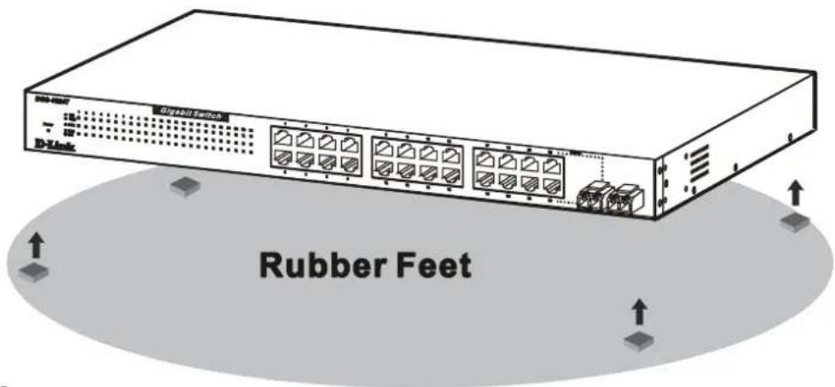
Figure 2-1. Switch installed on a Desktop or Shelf
Rack Installation
The Switch can be mounted in a standard 19" rack. Use the following diagrams to guide you.
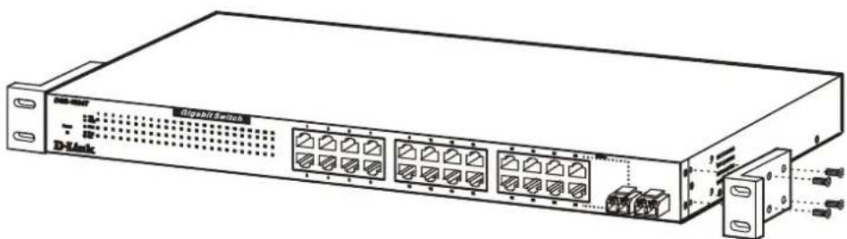
Figure 2-2. Fasten Mounting Brackets to Switch
Fasten the mounting brackets to the Switch using the screws provided. With the brackets attached securely, you can mount the Switch in a standard rack as shown in Figure 2-3 on the following page.
Mounting the Switch in a standard 19" rack:
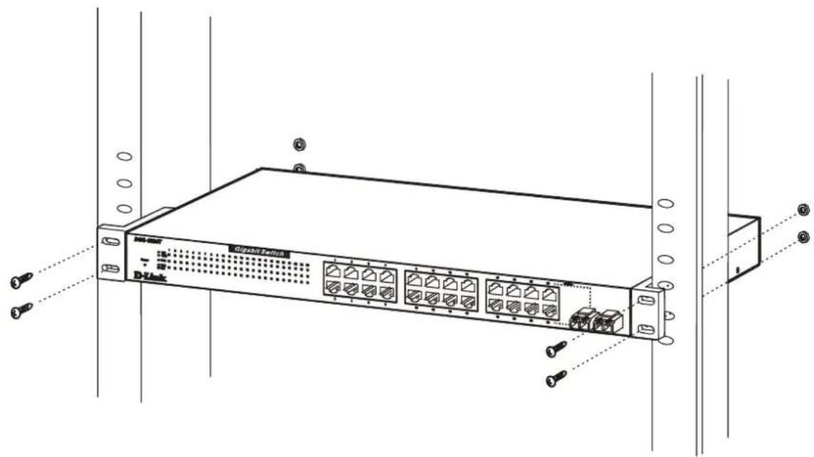
Figure 2-3. Switch in Rack
Power on
Plug one end of the AC power cord into the power connector of the switch and the other end into the local power source outlet.
Power Failure
As a precaution, in the event of a power failure, unplug the switch. When power is resumed, plug the switch back in.
3
IDENTIFYING EXTERNAL COMPONENTS
This chapter describes the front panel, rear panel, side panels, and LED indicators of the Switch.
Front Panel
The front panel of the DGS-1024T consists of an LED indicator for power and indicators for 24 individual ports for speed, full duplex, and link/activity.

Figure 3-1. Front panel view of the DGS-1024T
Rear Panel
The rear panel contains the AC power connector and one system fan used to dissipate heat. The AC power connector is a standard three-pronged connector that supports the power cord. Plug-in the female connector of the provided power cord into this socket, and the male side of the cord into a power outlet. Supported input voltages range from 100 \~ 240 VAC at 50 \~ 60 Hz.

Figure 3-2. Rear panel view of the Switch.
Side Panels
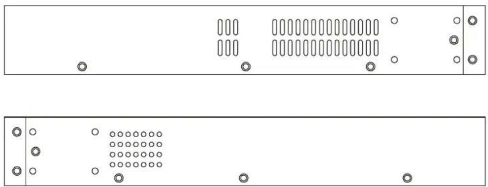
Each side panel contains heat vents that are used to dissipate heat. Do not block these openings, and leave at least 6 inches of space at the rear and sides of the switch for proper ventilation. Be reminded that without proper heat dissipation and air circulation, system components might overheat, which could lead to system failure.
natural_image
Front and back view of a server rack with indicator lights and ventilation slots (no text or symbols)Figure 3-3. Side panels (the right side panel is pictured on top)
LED Indicators
Power – This indicator lights when the Switch is turned on.
- Speed – There are three rows of indicators. The top LED is solid green for 1000 Mbps connections and solid amber for 100 Mbps connections. The indicator is off for 10 Mbps connections.
- FDX – This full-duplex indicator is located in the middle row. Solid green indicates a full-duplex connection. The LED is off for half-duplex connections.
- Link/Act – This indicator is located in the bottom row. In each case, these indicators light solid green when there is a secure connection (or link) to a device on any of the ports. The LEDs blink green whenever there is reception or transmission (i.e. Activity--Act) of data occurring on a port.
4
CONNECTING THE SWITCH
This chapter describes how to connect the Switch to your Gigabit Ethernet network.
Switch to End Node
End nodes include PCs outfitted with a 10, 100 or 10/100 Mbps RJ-45 Ethernet/Fast Ethernet Network Interface Card (NIC) and most routers.
An end node can be connected to the Switch via a two-pair Category 3, 4, 5, or 5e UTP/STP cable—for optimal performance, Category 5e is recommended. The end node should be connected to any of the ports of the Switch.
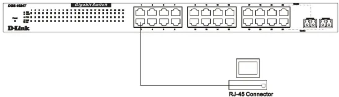
Figure 4-1. Switch connected to an end node
The Link/Act LEDs on the bottom row of the front panel of the device light green when the link is valid. The LED on the top row indicates port speed. It will light solid green for 1000 Mbps connections, solid amber for 100 Mbps connections, and will remain off for 10 Mbps connections. A blinking green LED on the bottom row indicates packet activity on that port.
Switch to Network Backbone or Server
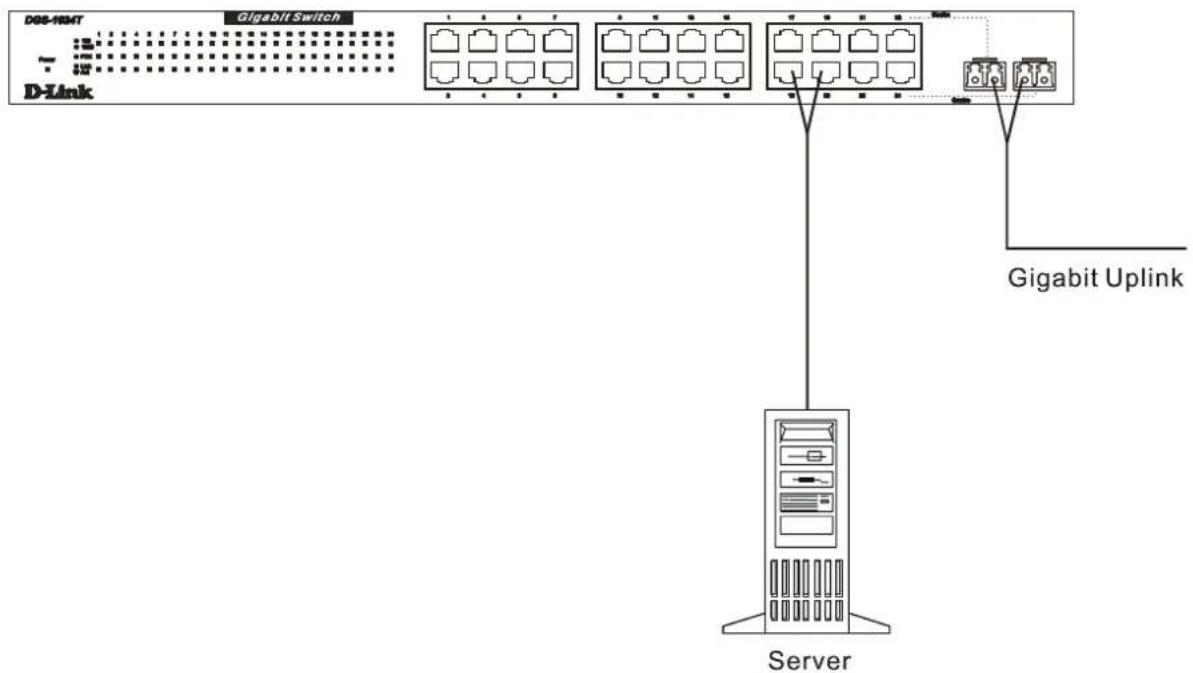
The two mini GBIC ports on the DGS-1024T are ideal for uplinking to a network backbone or network server. These ports operate at 1000 Mbps in full-duplex mode.
Connections to the mini GBIC ports are made using fiber optic cable, depending on the type of port. A valid connection is indicated when the Link LED is lit.
flowchart
graph TD
    A["DDB-IREMT"] --> B["Gigabit Switch"]
    B --> C["Server"]
    C --> D["Gigabit Uplink"]
    style A fill:#f9f,stroke:#333
    style B fill:#ccf,stroke:#333
    style C fill:#cfc,stroke:#333
    style D fill:#fcc,stroke:#333
Figure 4-2. Gigabit uplink connection
5
WARRANTY AND REGISTRATION
All countries and regions except USA
D-Link warrants its hardware products to be free from defects in workmanship and materials, under normal use and service, for the following periods measured from date of purchase from D-Link or its Authorized Reseller:
| Product | Type | Warranty | Period |
| Complete | products | One | year |
| Spare parts and spare kits | 90 days |
The one-year period of warranty on complete products applies on condition that the product's Registration Card is filled out and returned to a D-Link office within ninety (90) days of purchase. A list of D-Link offices is provided at the back of this manual, together with a copy of the Registration Card. Failing such timely registration of purchase, the warranty period shall be limited to 90 days.
If the product proves defective within the applicable warranty period, D-Link will provide repair or replacement of the product. D-Link shall have the sole discretion whether to repair or replace, and replacement product may be new or reconditioned. Replacement product shall be of equivalent or better specifications, relative to the defective product, but need not be identical. Any product or part repaired by D-Link pursuant to this warranty shall have a warranty period of not less than 90 days, from date of such repair, irrespective of any earlier expiration of original warranty period. When D-Link provides replacement, then the defective product becomes the property of D-Link.
Warranty service may be obtained by contacting a D-Link office within the applicable warranty period, and requesting a Return Material Authorization (RMA) number. If a Registration Card for the product in question has not been returned to D-Link, then a proof of purchase (such as a copy of the dated purchase invoice) must be provided. If Purchaser's circumstances require special handling of warranty correction, then at the time of requesting RMA number, Purchaser may also propose special procedure as may be suitable to the case.
After an RMA number is issued, the defective product must be packaged securely in the original or other suitable shipping package to ensure that it will not be damaged in transit, and the RMA number must be prominently marked on the outside of the package. The package must be mailed or otherwise shipped to D-Link with all costs of mailing/shipping/insurance prepaid; D-Link will ordinarily reimburse Purchaser for mailing/shipping/insurance expenses incurred for return of defective product in accordance with this warranty. D-Link shall never be responsible for any software, firmware, information, or memory data of Purchaser contained in, stored on, or integrated with any product returned to D-Link pursuant to this warranty.
Any package returned to D-Link without an RMA number will be rejected and shipped back to Purchaser at Purchaser's expense, and D-Link reserves the right in such a case to levy a reasonable handling charge in addition mailing or shipping costs.
LIMITATION OF WARRANTIES
IF THE D-LINK PRODUCT DOES NOT OPERATE AS WARRANTED ABOVE, THE CUSTOMER'S SOLE REMEDY SHALL BE, AT D-LINK'S OPTION. REPAIR OR REPLACEMENT. THE FOREGOING WARRANTIES AND REMEDIES ARE EXCLUSIVE AND ARE IN LIEU OF ALL OTHER WARRANTIES, EXPRESSED OR IMPLIED, EITHER IN FACT OR BY OPERATION OF LAW, STATUTORY OR OTHERWISE, INCLUDING WARRANTIES OF MERCHANTABILITY AND FITNESS FOR A PARTICULAR PURPOSE. D-LINK NEITHER ASSUMES NOR AUTHORIZES ANY OTHER PERSON TO ASSUME FOR IT ANY OTHER LIABILITY IN CONNECTION WITH THE SALE, INSTALLATION MAINTENANCE OR USE OF D-LINK'S PRODUCTS.
D-LINK SHALL NOT BE LIABLE UNDER THIS WARRANTY IF ITS TESTING AND EXAMINATION DISCLOSE THAT THE ALLEGED DEFECT IN THE PRODUCT DOES NOT EXIST OR WAS CAUSED BY THE CUSTOMER'S OR ANY THIRD PERSON'S MISUSE, NEGLECT, IMPROPER INSTALLATION OR TESTING, UNAUTHORIZED ATTEMPTS TO REPAIR, OR ANY OTHER CAUSE BEYOND THE RANGE OF THE INTENDED USE, OR BY ACCIDENT, FIRE, LIGHTNING OR OTHER HAZARD.
LIMITATION OF LIABILITY
IN NO EVENT WILL D-LINK BE LIABLE FOR ANY DAMAGES, INCLUDING LOSS OF DATA, LOSS OF PROFITS, COST OF COVER OR OTHER INCIDENTAL, CONSEQUENTIAL OR INDIRECT DAMAGES ARISING OUT THE INSTALLATION, MAINTENANCE, USE, PERFORMANCE, FAILURE OR INTERRUPTION OF A D- LINK PRODUCT, HOWEVER CAUSED AND ON ANY THEORY OF LIABILITY. THIS LIMITATION WILL APPLY EVEN IF D-LINK HAS BEEN ADVISED OF THE POSSIBILITY OF SUCH DAMAGE.
IF YOU PURCHASED A D-LINK PRODUCT IN THE UNITED STATES, SOME STATES DO NOT ALLOW THE LIMITATION OR EXCLUSION OF LIABILITY FOR INCIDENTAL OR CONSEQUENTIAL DAMAGES. SO THE ABOVE LIMITATION MAY NOT APPLY TO YOU.
D-Link Offices for Registration and Warranty Service
The product's Registration Card, provided at the back of this manual, must be sent to a D-Link office. To obtain an RMA number for warranty service as to a hardware product, or to obtain warranty service as to a software product, contact the D-Link office nearest you. An addresses/telephone/fax list of D-Link offices is provided in the back of this manual.
Trademarks
Copyright ©2003 D-Link Corporation.
Contents subject to change without prior notice.
D-Link is a registered trademark of D-Link Corporation/D-Link Systems, Inc.
All other trademarks belong to their respective proprietors.
Copyright Statement
No part of this publication may be reproduced in any form or by any means or used to make any derivative such as translation, transformation, or adaptation without permission from D-Link Corporation/D-Link Systems Inc., as stipulated by the United States Copyright Act of 1976
FCC Warning
This equipment has been tested and found to comply with the limits for a Class A digital device, pursuant to Part 15 of the FCC Rules. These limits are designed to provide reasonable protection against harmful interference when the equipment is operated in a commercial environment. This equipment generates, uses, and can radiate radio frequency energy and, if not installed and used in accordance with this user's guide, may cause harmful interference to radio communications. Operation of this equipment in a residential area is likely to cause harmful interference in which case the user will be required to correct the interference at his own expense.
This device complies with part 15 of the FCC Rules. Operation is subject to the following two conditions: (1) This device may not cause harmful interference, and (2) this device must accept any interference received, including interference that may cause undesired operation.
CE Mark Warning
This is a Class A product. In a domestic environment this product may cause radio interference in which case the user may be required to take adequate measures.
Warnung!
Subject to the terms and conditions set forth herein, D-Link Systems, Inc. ("D-Link") provides this Limited warranty for its product only to the person or entity that originally purchased the product from:
• D-Link or its authorized reseller or distributor and
- Products purchased and delivered within the fifty states of the United States, the District of Columbia, U.S. Possessions or Protectorates, and U.S. Military Installations, addresses with an APO or FPO.
Limited Warranty: D-Link warrants that the hardware portion of the D-Link products described below will be free from material defects in workmanship and materials from the date of original retail purchase of the product, for the period set forth below applicable to the product type (“Warranty Period”), except as otherwise stated herein.
5-Year Limited Warranty for the Product(s) is defined as follows:
• Hardware (excluding power supplies and fans) Five (5) Years
• Power Supplies and Fans Three (3) Year
- Spare parts and spare kits Ninety (90) days
D-Link's sole obligation shall be to repair or replace the defective Hardware during the Warranty Period at no charge to the original owner or to refund at D-Link's sole discretion. Such repair or replacement will be rendered by D-Link at an Authorized D-Link Service Office. The replacement Hardware need not be new or have an identical make, model or part. D-Link may in its sole discretion replace the defective Hardware (or any part thereof) with any reconditioned product that D-Link reasonably determines is substantially equivalent (or superior) in all material respects to the defective Hardware. Repaired or replacement Hardware will be warranted for the remainder of the original Warranty Period from the date of original retail purchase. If a material defect is incapable of correction, or if D-Link determines in its sole discretion that it is not practical to repair or replace the defective Hardware, the price paid by the original purchaser for the defective Hardware will be refunded by D-Link upon return to D-Link of the defective Hardware. All Hardware (or part thereof) that is replaced by D-Link, or for which the purchase price is refunded, shall become the property of D-Link upon replacement or refund.
Limited Software Warranty: D-Link warrants that the software portion of the product ("Software") will substantially conform to D-Link's then current functional specifications for the Software, as set forth in the applicable documentation, from the date of original retail purchase of the Software for a period of ninety (90) days ("Warranty Period"), provided that the Software is properly installed on approved hardware and operated as contemplated in its documentation. D-Link further warrants that, during the Warranty Period, the magnetic media on which D-Link delivers the Software will be free of physical defects. D-Link's sole obligation shall be to replace the non-conforming Software (or defective media) with software that substantially conforms to D-Link's functional specifications for the Software or to refund at D-Link's sole discretion. Except as otherwise agreed by D-Link in writing, the replacement Software is provided only to the original licensee, and is subject to the terms and conditions of the license granted by D-Link for the Software. Software will be warranted for the remainder of the original Warranty Period from the date or original retail purchase. If a material non-conformance is incapable of correction, or if D-Link determines in its sole discretion that it is not practical to replace the non-conforming Software, the price paid by the original licensee for the non-conforming Software will be refunded by D-Link; provided that the non-conforming Software (and all copies thereof) is first returned to D-Link. The license granted respecting any Software for which a refund is given automatically terminates.
Non-Applicability of Warranty: The Limited Warranty provided hereunder for hardware and software of D-Link's products, will not be applied to and does not cover any product purchased through the inventory clearance or liquidation sale or other sales in which D-Link, the sellers, or the liquidators expressly disclaim their warranty obligation pertaining to the product and in that case, the product is being sold "As-Is" without any warranty whatsoever including, without limitation, the Limited Warranty as described herein, notwithstanding anything stated herein to the contrary.
Submitting A Claim: Any claim under this limited warranty must be submitted in writing before the end of the Warranty Period to an Authorized D-Link Service Office.
- The customer must submit as part of the claim a written description of the Hardware defect or Software nonconformance in sufficient detail to allow D-Link to confirm the same.
- The original product owner must obtain a Return Material Authorization (“RMA”) number from the Authorized D-Link Service Office and, if requested, provide written proof of purchase of the product (such as a copy of the dated purchase invoice for the product) before the warranty service is provided.
- After an RMA number is issued, the defective product must be packaged securely in the original or other suitable shipping package to ensure that it will not be damaged in transit, and the RMA number must be prominently marked on the outside of the package. Do not include any manuals or accessories in the shipping package. D-Link will only replace the defective portion of the Product and will not ship back any accessories.
- The customer is responsible for all shipping charges to D-Link. No Charge on Delivery (“COD”) is allowed. Products sent COD will either be rejected by D-Link or become the property of D-Link. Products should be fully insured by the customer and shipped to D-Link Systems, Inc., 53 Discovery Drive, Irvine, CA 92618. D-Link will not be held responsible for any packages that are lost in transit to D-Link. The repaired or replaced packages will be shipped via UPS Ground or any common carrier selected by D-Link, with shipping charges prepaid. Expedited shipping is available if shipping charges are prepaid by the customer.
D-Link may reject or return any product that is not packaged and shipped in strict compliance with the foregoing requirements, or for which an RMA number is not visible from the outside of the package. The product owner agrees to pay D-Link's reasonable handling and return shipping charges for any product that is not packaged and shipped in accordance with the foregoing requirements, or that is determined by D-Link not to be defective or non-conforming.
What Is Not Covered: This limited warranty provided by D-Link does not cover: Products, if in D-Link's judgment, have been subjected to abuse, accident, alteration, modification, tampering, negligence, misuse, faulty installation, lack of reasonable care, repair or service in any way that is not contemplated in the documentation for the product, or if the model or serial number has been altered, tampered with, defaced or removed; Initial installation, installation and removal of the product for repair, and shipping costs; Operational adjustments covered in the operating manual for the product, and normal maintenance; Damage that occurs in shipment, due to act of God, failures due to power surge, and cosmetic damage; Any hardware, software, firmware or other products or services provided by anyone other than D-Link; Products that have been purchased from inventory clearance or liquidation sales or other sales in which D-Link, the sellers, or the liquidators expressly disclaim their warranty obligation pertaining to the product. Repair by anyone other than D-Link or an Authorized D-Link Service Office will void this Warranty.
Disclaimer of Other Warranties: EXCEPT FOR THE LIMITED WARRANTY SPECIFIED HEREIN, THE PRODUCT IS PROVIDED "AS-IS" WITHOUT ANY WARRANTY OF ANY KIND WHATSOEVER INCLUDING, WITHOUT LIMITATION, ANY WARRANTY OF MERCHANTABILITY, FITNESS FOR A PARTICULAR PURPOSE AND NON-INFRINGEMENT.
IF ANY IMPLIED WARRANTY CANNOT BE DISCLAIMED IN ANY TERRITORY WHERE A PRODUCT IS SOLD, THE DURATION OF SUCH IMPLIED WARRANTY SHALL BE LIMITED TO NINETY (90) DAYS. EXCEPT AS EXPRESSLY COVERED UNDER THE LIMITED WARRANTY PROVIDED HEREIN, THE ENTIRE RISK AS TO THE QUALITY, SELECTION AND PERFORMANCE OF THE PRODUCT IS WITH THE PURCHASER OF THE PRODUCT.
Limitation of Liability: TO THE MAXIMUM EXTENT PERMITTED BY LAW, D-LINK IS NOT LIABLE UNDER ANY CONTRACT, NEGLIGENCE, STRICT LIABILITY OR OTHER LEGAL OR EQUITABLE THEORY FOR ANY LOSS OF USE OF THE PRODUCT, INCONVENIENCE OR DAMAGES OF ANY CHARACTER, WHETHER DIRECT, SPECIAL, INCIDENTAL OR CONSEQUENTIAL (INCLUDING, BUT NOT LIMITED TO, DAMAGES FOR LOSS OF GOODWILL, LOSS OF REVENUE OR PROFIT, WORK STOPPAGE, COMPUTER FAILURE OR MALFUNCTION, FAILURE OF OTHER EQUIPMENT OR COMPUTER PROGRAMS TO WHICH D-LINK'S PRODUCT IS CONNECTED WITH, LOSS OF INFORMATION OR DATA CONTAINED IN, STORED ON, OR INTEGRATED WITH ANY PRODUCT RETURNED TO D-LINK FOR WARRANTY SERVICE) RESULTING FROM THE USE OF THE PRODUCT, RELATING TO WARRANTY SERVICE, OR ARISING OUT OF ANY BREACH OF THIS LIMITED WARRANTY, EVEN IF D-LINK HAS BEEN ADVISED OF THE POSSIBILITY OF SUCH DAMAGES. THE SOLE REMEDY FOR A BREACH OF THE FOREGOING LIMITED WARRANTY IS REPAIR, REPLACEMENT OR REFUND OF THE DEFECTIVE OR NON-CONFORMING PRODUCT. THE MAXIMUM LIABILITY OF D-LINK UNDER THIS WARRANTY IS LIMITED TO THE PURCHASE PRICE OF THE PRODUCT COVERED BY THE WARRANTY. THE FOREGOING EXPRESS WRITTEN WARRANTIES AND REMEDIES ARE EXCLUSIVE AND ARE IN LIEU OF ANY OTHER WARRANTIES OR REMEDIES, EXPRESS, IMPLIED OR STATUTORY.
Governing Law: This Limited Warranty shall be governed by the laws of the state of California. Some states do not allow exclusion or limitation of incidental or consequential damages, or limitations on how long an implied warranty lasts, so the foregoing limitations and exclusions may not apply. This limited warranty provides specific legal rights and the product owner may also have other rights which vary from state to state.
Trademarks: D-Link is a registered trademark of D-Link Systems, Inc. Other trademarks or registered trademarks are the property of their respective manufacturers or owners.
Copyright Statement: No part of this publication or documentation accompanying this Product may be reproduced in any form or by any means or used to make any derivative such as translation, transformation, or adaptation without permission from D-Link Corporation/D-Link Systems, Inc., as stipulated by the United States Copyright Act of 1976. Contents are subject to change without prior notice. Copyright© 2003 by D-Link Corporation/D-Link Systems, Inc. All rights reserved.
CE Mark Warning: This is a Class A product. In a domestic environment, this product may cause radio interference, in which case the user may be required to take adequate measures.
FCC Statement: This equipment has been tested and found to comply with the limits for a Class A digital device, pursuant to part 15 of the FCC Rules. These limits are designed to provide reasonable protection against harmful interference in a residential installation. This equipment generates uses and can radiate radio frequency energy and, if not installed and used in accordance with the instructions, may cause harmful interference to radio communication. However, there is no guarantee that interference will not occur in a particular installation. If this equipment does cause harmful interference to radio or television reception, which can be determined by turning the equipment off and on, the user is encouraged to try to correct the interference by one or more of the following measures:
• Reorient or relocate the receiving antenna.
- Increase the separation between the equipment and receiver.
- Connect the equipment into an outlet on a circuit different from that to which the receiver is connected.
- Consult the dealer or an experienced radio/TV technician for help.
Register your D-Link product online at http://support.dlink.com/register/
A
TECHNICAL SPECIFICATIONS
| General | |
| Standards: IEEE 802.3 10BASE-T EthernetIEEE 802.3u 100BASE-TX Fast EthernetIEEE 802.3z 1000BASE-SX/LX Gigabit Fast EthernetIEEE802.3ab 1000BASE-TIEEE 802.3x Flow ControlANSI/IEEE Std 802.3 N-Way auto-negotiation | |
| Protocol: | CSMA/CD |
| Data Transfer Rate: | Ethernet:10 Mbps (half duplex)20 Mbps (full duplex)Fast Ethernet:100Mbps (half duplex)200Mbps (full duplex)Gigabit Ethernet:2000 Mbps (full-duplex only) |
| Topology: | Star |
| Network Cables10BASE-T: | UTP Category 3, 4, 5 (100 meters max.)EIA/TIA- 568 100-ohm STP (100 meters max.) |
| 100BASE-TX: | UTP Cat. 5 (100 meters max.)EIA/TIA-568 100-ohm STP (100 meters max.) |
| 1000BASE-T: | UTP Cat. 5e (100 meters max.)EIA/TIA-568B 100-ohm STP (100 meters max.) |
| Mini GBIC:1000BASE-SX | 50/125μm Multimode Fiber-optic (550 meters max.)62.5/125μm Multimode Fiber-optic (275 meters max.) |
| 1000BASE-LX | 50/125μm Multimode Fiber-optic (550 meters max.)62.5/125μm Multimode Fiber-optic (550 meters max.)10μm Single-mode Fiber-optic (5 km max.) |
| Number of Ports: | 24 10/100/1000 Mbps ports, including 2 Combo ports |
| Physical and Environmental | |
| AC input | 100 - 240 VAC, 50 - 60 Hz, 1.A Max, Internal universal power supply |
| Power Consumption: | 75 watts maximum |
| DC Fans: 1 built-in | 75 x 75 x 30 mm fan |
| Operating Temperature: | 32 ° ~ 104 °F (0 ° ~ 40 °C) |
| Storage Temperature: | -13 ° ~ 131 °F (-25 ° ~ 55 °C) |
| Humidity: 5% ~ 95% non-condensing | |
| Dimensions: 441mm x 309mm x 44mm (19" rack mount, 1U) | |
| Weight: | 4.2 Kg |
| EMI: | CE Mark Class A, C-Tick Class A, FCC Class A, BSMI Class A |
| Safety: | CSA International |
| Performance | |
| Transmission Method: | Store-and-forward |
| RAM Buffer: (Packet buffer) | 2 MB per device |
| MAC Address Table: | Supports 32K MAC address |
| Packet Filtering/Forwarding Rate: | 1,488,095 pps per port (for 1000Mbps)148,809 pps per port (for 100Mbps)14,880 pps per port (for 10Mbps) |
B
CABLE LENGTHS
Use the following table to as a guide for the maximum cable lengths:
| Standard Media | Type | Maximum Distance |
| Mini—GBIC1000BASE-SX | 50/125μm Multimode Fiber62.5/125μm Multimode Fiber | 550 Meters275 Meters |
| Mini—GBIC1000BASE-LX | 50/125μm Multimode Fiber62.5/125μm Multimode Fiber10μm Single-mode Fiber | 550 Meters550 Meters5km |
| 1000BASE-T | Category 5e UTP Cable(1000 Mbps) | 100 Meters |
| 100BASE-TX | Category 5 UTP Cable(100 Mbps) | 100 Meters |
| 10BASE-T | Category 3 UTP Cable(10 Mbps) | 100 Meters |
Australia
D-Link
Australasia
1 Giffnock Avenue, North Ryde, NSW 2113.
Sydney,
[Non-Text]
TEL: 61-2-8899-1800 FAX: 61-2-8899-1868
TOLL FREE (Australia): 1800-177100
TOLL FREE (New Zealand): 0800-900900
URL:
www.dlink.com.au
E-MAIL:
support@dlink.com.au & info@dlink.com.au
Level 1. 434 St. Kilda Road, Melbourne,
Victoria 3004 Australia
TEL: 61-3-9281-3232 FAX: 61-3-9281-3229
MOBILE:
0412-660-064
Canada
D-Link
Canada
2180 Winston Park Drive, Oakville,
Ontario, L6H 5W1 Canada
TEL: 1-905-829-5033 FAX: 1-905-829-5095
BBS:
1-965-279-8732
TOLL FREE: 1-800-354-6522 URL: www.dlink.ca
FTP: ftp.dlinknet.com E-MAIL: techsup@dlink.ca
Chile D-Link South America
Isidora Goyenechea 2934 Of. 702, Las Condes Fono,
2323185, Santiago, Chile, S. A.
TEL: 56-2-232-3185 FAX: 56-2-232-0923
URL:
www.dlink.cl
E-MAIL: ccasassu@dlink.cl & tsilva@dlink.cl
China
D-Link
China
15^th Floor, Science & Technology Tower, No.11,
Baishiqiao Road, Haidan District, 100081 Beijing, China
TEL: 86-10-68467106 FAX: 86-10-68467110
URL:
www.dlink.com.cn
E-MAIL:
liwei@digitalchina.com.cn
Denmark
D-Link
Denmark
Naverland 2, DK-2600 Glostrup, Copenhagen, Denmark
TEL: 45-43-969040 FAX:45-43-424347
URL: www.dlink.dk E-MAIL: info@dlink.dk
Egypt D-Link Middle East
7 Assem Ebn Sabet Street, Heliopolis, Cairo, Egypt
TEL: 20-2-635-6176 FAX: 20-2-635-6192
URL:
www.dlink-me.com
E-MAIL: support@dlink-me.com & fateen@dlink-me.com
Finland
D-Link Finland
Pakkalankuja 7A, FIN-0150 VANTAA, Finland
TEL: 358-9-2707-5080 FAX: 358-9-2702-5081
URL:
www.dlink-fi.com
France
D-Link
France
Le Florilege, No. 2, Allea de la Fresnerie,
78330 Fontenay Le Fleury, France
TEL: 33-1-3023-8688 FAX: 33-1-3023-8689
URL:
www.dlink-france.fr
E-MAIL:
info@dlink-france.fr
Plot No.5, Bandra-Kurla Complex Rd., Off Cst Rd.,
Santacruz (East), Mumbai, 400 098 India
TEL:
91-022-652-6696/6578/6623
FAX:
91-022-652-8914/8476
URL: www.dlink-india.com, www.dlink.co.in &
tushars@dlink-india.com E-MAIL: service@dlink.india.com
Italy D-Link Mediterraneo Srl/D-Link Italia
Via Nino Bonnet n. 6/B, 20154, Milano, Italy
TEL: 39-02-2900-0676 FAX: 39-02-2900-1723
URL: www.dlink.it E-MAIL: info@dlink.it
Japan
D-Link
Japan
10F, 8-8-15 Nishigotahda, Shinagawa, Tokyo 141, Japan
TEL: 81-3-5434-9678 FAX: 81-3-5434-9868
URL: www.d-link.co.jp E-MAIL: kida@d-link.co.jp
Netherlands
D-Link
Benelux
Fellenoord 1305611 ZB, Eindhoven, the Netherlands
TEL: 31-40-2668713 FAX: 31-40-2668666
URL:
www.d-link-benelux.nl
Norway
D-Link
Norway
Waldemar Thranesgate 77, 0175 Oslo, Norway
TEL: 47-22-991890 FAX: 47-22-207039
URL:
www.dlink.no
Russia D-Link Russia
Michurinski Prospekt 49, 117607 Moscow, Russia
TEL: 7-095-737-3389 & 7-095-737-3492
FAX: 7-095-737-3390 URL: www.dlink.ru
E-MAIL:
vl@dlink.ru
Singapore D-Link International
International Business Park, #03-12 The Synergy,
Singapore
609917
TEL: 65-774-6233 FAX: 65-774-6322
E-MAIL: info@dlink.com.sg URL: www.dlink-intl.com
South Africa D-Link South Africa
Unit 2, Parkside, 86 Oak Avenue, Highveld Technopark,
Centurion, Gauteng, South Africa
TEL: 27 (0) 12-665-2165 FAX: 27 (0) 12-665-2186
URL: www.d-link.co.za E-MAIL: attie@d-link.co.za
Spain
D-Link
Iberia
C/Sabino De Arana, 56 Bajos, 08028 Barcelona, Spain
TEL: 34 93 4090770 FAX: 34 93 4910795
URL: www.dlinkiberia.es E-MAIL: info@dlinkiberia.es
Sweden
D-Link
Sweden
P. O. Box 15036, S-167 15 Bromma, Sweden
TEL: 46-(0) 8-564-61900 FAX: 46-(0) 8-564-61901
E-MAIL: info@dlink.se URL: www.dlink.se
Taiwan
D-Link Taiwan
2F, No. 233-2 Pao-chiao Rd, Hsin-tien, Taipei, Taiwan
TEL: 886-2-2916-1600 FAX: 886-2-2914-6299
URL: www.dlink.com.tw E-MAIL: dssqa@tsc.dlinktw.com.tw
Turkey
D-Link Middle East
Mecidiyekoy, Istanbul, Turkey
TEL: 90-212-213-3400 FAX: 90-212-213-3420
E-MAIL:
smorovati@dlink-me.com
U.A.E. D-Link Middle East
CHS Aptec (Dubai), P.O. Box 33550 Dubai U.A.E.
TEL: 971-4-366-885 FAX: 971-4-355-941
E-MAIL:
Wxavier@dlink-me.co
U.K.
D-Link
Europe
4^th Floor, Merit House, Edgware Road, Colindale, London
NW9 5AB United Kingdom
TEL: 44 (0) 20-8731-5555 FAX: 44 (0) 20-8731-5511
BBS: 44 (0) 181-235-5511
URL: www.dlink.co.uk E-MAIL: info@dlink.co.uk
U.S.A.
D-Link
U.S.A.
53 Discovery Drive, Irvine, CA 92618, USA
TEL: 1-949-788-0805 FAX: 1-949-753-7033
BBS: 1-949-455-1779 & 1-949-455-9616
INFO: 1-800-326-1688 URL: www.dlink.com
E-MAIL:
tech@dlink.com & support@dlink.com
- Unmanaged Gigabit Ethernet Switch
- User's Guide
- Table of Contents
- ABOUT THIS GUIDE
- Overview of this User's Guide
- 1
- INTRODUCTION
- Fast Ethernet Technology
- Gigabit Ethernet Technology
- Switching Technology
- DGS-1024T Gigabit Ethernet Switch
- General Description of Switch
- Performance features
- Ports
- 2
- UNPACKING AND SETUP
- Unpacking
- Setup
- Desktop or Shelf Installation
- Rack Installation
- Power on
- Power Failure
- 3
- IDENTIFYING EXTERNAL COMPONENTS
- Front Panel
- Rear Panel
- Side Panels
- LED Indicators
- 4
- CONNECTING THE SWITCH
- Switch to End Node
- Switch to Network Backbone or Server
- 5
- WARRANTY AND REGISTRATION
- All countries and regions except USA
- LIMITATION OF WARRANTIES
- LIMITATION OF LIABILITY
- D-Link Offices for Registration and Warranty Service
- Trademarks
- Copyright Statement
- FCC Warning
- CE Mark Warning
- Warnung!
- A
- TECHNICAL SPECIFICATIONS
- B
- CABLE LENGTHS
- Australia
- D-Link
- Australasia
- Canada
- Chile D-Link South America
- China
- Denmark
- Egypt D-Link Middle East
- Finland
- D-Link Finland
- France
- Italy D-Link Mediterraneo Srl/D-Link Italia
- Japan
- Netherlands
- Benelux
- Norway
- Russia D-Link Russia
- Singapore D-Link International
- South Africa D-Link South Africa
- Spain
- Iberia
- Sweden
- Taiwan
- D-Link Taiwan
- Turkey
- D-Link Middle East
- U.A.E. D-Link Middle East
- U.K.
- Europe
- U.S.A.
Brand : D-LINK
Model : DGS-1024T
Category : Network switch