
OG-3GDA-2X4 - Receiver AJA - Free user manual and instructions
Find the device manual for free OG-3GDA-2X4 AJA in PDF.


| Product Type | Professional 3G-SDI Receiver |
| Model | OG-3GDA-2X4 |
| Brand | AJA |
| Dimensions (W x D x H) | 8.6 x 5.7 x 1.7 inches (218 x 145 x 43 mm) |
| Weight | 1.5 lbs (0.68 kg) |
| Power Supply | 12V DC, 15W typical |
| Input Connectors | 2 x BNC (3G-SDI) |
| Output Connectors | 4 x BNC (3G-SDI) |
| Supported Video Formats | 1080p, 1080i, 720p, NTSC, PAL |
| Supported Audio | Embedded SDI audio (up to 16 channels) |
| Key Functions | Signal distribution, reclocking, equalization |
| Operating Temperature | 32°F to 104°F (0°C to 40°C) |
| Storage Temperature | -4°F to 140°F (-20°C to 60°C) |
| Humidity | 10% to 90% non-condensing |
| Cleaning Instructions | Use dry cloth; avoid liquids and abrasives |
| Safety Precautions | Use only provided power adapter; avoid exposure to moisture |
| Spare Parts Availability | Contact AJA support for replacement parts |
| Repairability | Serviceable by qualified technician only |
| Warranty | 2 years limited |
| Compliance | CE, FCC Class A, RoHS |
Frequently Asked Questions - OG-3GDA-2X4 AJA
User questions about OG-3GDA-2X4 AJA
0 question about this device. Answer the ones you know or ask your own.
Ask a new question about this device
Download the instructions for your Receiver in PDF format for free! Find your manual OG-3GDA-2X4 - AJA and take your electronic device back in hand. On this page are published all the documents necessary for the use of your device. OG-3GDA-2X4 by AJA.
USER MANUAL OG-3GDA-2X4 AJA
OG-3GDA Series openGear Cards
natural_image
Green printed circuit board with multiple labeled components and connectors, no readable text or symbols present.Installation and Operation Guide
Trademarks
AJA® and Because it matters. are registered trademarks of AJA Video Systems, Inc. for use with most AJA products. AJATM is a trademark of AJA Video Systems, Inc. for use with recorder, router, software and camera products. Because it matters. is a trademark of AJA Video Systems, Inc. for use with camera products.
Corvid Ultra ® , Io ® , Ki Pro ® , KONA ® , KUMO ® , ROI ® and T-Tap ® are registered trademarks of AJA Video Systems, Inc.
AJA Control Room™, KiStor™, Science of the Beautiful™, TruScale™, V2Analog™ and V2Digital™ are trademarks of AJA Video Systems, Inc.
All other trademarks are the property of their respective owners.
Copyright
Copyright © 2020 AJA Video Systems, Inc. All rights reserved. All information in this manual is subject to change without notice. No part of the document may be reproduced or transmitted in any form, or by any means, electronic or mechanical, including photocopying or recording, without the express written permission of AJA Video Systems, Inc.
Contacting AJA Support
When calling for support, have all information at hand prior to calling. To contact AJA for sales or support, use any of the following methods:
Telephone +1.530.271.3190
FAX +1.530.271.3140
Web https://www.aja.com
Support Email support@aja.com
Sales Email sales@aja.com
Contents
Notices 2
Trademarks 2
Copyright 2
Contacting AJA Support 2
Chapter 1 – Introduction .....4
Card Overview 4
Features....4
OG-3GDA-1x9 4
OG-3GDA-2x4 5
LED Indicators 5
Block Diagram for OG-3GDA-1x9 6
Block Diagram for OG-3GDA-2x4 in Dual 1x4 Mode . . . . . . . . . . . . . . . . . . . . . . . . . . . . . . . . . . . . . . . . . . . . . . . . . . 6
Block Diagram for OG-3GDA-2x4 in Single 1x8 Mode ..... 7
I/O Connections for OG-3GDA-1x9. 7
Inverted and Non-Inverted Outputs....7
I/O Connections for OG-3GDA-2x4, Dual 1x4 Mode .....8
Inverted and Non-Inverted Outputs....8
I/O Connections for OG-3GDA-2x4, Single 1x8 Mode. . . . . . . . . . . . . . . . . . . . . . . . . 8
Inverted and Non-Inverted Outputs....8
Signal Indicators in the Dashboard Control System 9
User Controls 10
Dashboard Control System.... 11
openGear and AJA 11
Installation.... 11
Summary 11
Unpacking 11
Rear OG-3GDA Series Card Installation 12
Front OG-3GDA Series Card Installation. 13
Cabling 14
Chapter 2 – Operation....15
Using the Dashboard Control System.... 15
Requirements 15
Configuration Settings Stored in OG Card 15
Control Interface Basic Components 15
Basic Tree View of Frames and Cards. 16
Card Information and Status. 16
Parameter Controls. 16
Card Tab Screen.... 17
Input Status Tab Screen—Dual 2x4 Mode ..... 18
Input Status Tab Screen—Single 1x8 Mode ..... 19
Setup Tab Screen 20
Uploading New Software. 20
Rebooting 22
Appendix A – Specifications ..... 24
OG-3GDA-1x9 24
OG-3GDA-2x4. 24
Appendix B – Safety and Compliance ..... 26
Warranty and Liability Information....35
Limited Warranty on Hardware. 35
Limitation of Liability 35
Governing Law and Language; Your Rights 35
Index. 37
Chapter 1 – Introduction

natural_image
Two green electronic circuit boards labeled 'AJA' with various components and connectors, no readable text or symbols beyond labels.Card Overview
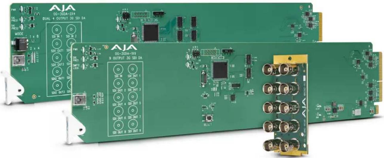
AJA's OG-3GDA Series cards are state-of-the-art, openGear-compatible, 3G-SDI distribution amplifiers.
Features
- openGear compatible card (requires 2 slots, rear card included)
- Use with openGear 2RU frames
- Controlled by Dashboard network control software
• Automatic detection and re-clocking of 270Mb, 1.5Gb, and 3Gb SDI data rates - Excellent input jitter tolerance and low jitter re-clocked outputs
- Input Present and Input SMPTE Lock LEDs (OG-3GDA-1x9)
- Input Present LEDs (OG-3GDA-2x4)
- Hot-swap capable
- 5 year warranty
OG-3GDA-1x9
For the OG-3GDA-1x9, the incoming SD, HD or 3G signal is distributed to each of the nine 3G-SDI outputs, allowing the same signal to be sent to multiple destinations simultaneously.
If the incoming SD, HD or 3G signal is one of the five SMPTE rates (270 Mbps, 1.483 Gbps, 1.485 Gbps, 2.966 Gbps, 2.970 Gbps), the signal will be reclocked, and both the SMPTE Lock LED and Signal Present LED will illuminate. Otherwise, if a non-SMPTE input is detected, the signal will bypass the reclocker and only the Signal Present LED will illuminate.
OG-3GDA-2x4
The OG-3GDA-2x4 offers two modes: Dual 1x4 or Single 1x8. In either mode, the OG-3GDA-2x4 allows the same signal or signals to be sent to multiple destinations simultaneously.
The incoming SD, HD or 3G signal(s) will be reclocked if it is one of the five SMPTE rates (270 Mbps, 1.483 Gbps, 1.485 Gbps, 2.966 Gbps, 2.970 Gbps). Otherwise the signal(s) will bypass the reclocker and be present at the outputs.
When a SD, HD, or 3G signal is detected, regardless of its compliance to SMPTE standards, the Signal Present 1 and/or Signal Present 2 LEDs will illuminate, depending on where the signal input is detected.
Dual 1x4 Mode
In Dual 1x4 Mode, the incoming SD, HD or 3G signals coming in through SDI Input 1 and SDI Input 2 are distributed to the two corresponding sets of four 3G-SDI outputs. The two DAs are completely independent.
Single 1x8 Mode
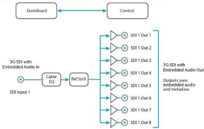
In Single 1x8 Mode, the SD, HD or 3G signal coming in through SDI Input 1 is distributed to the eight 3G-SDI outputs. Both Signal Present LEDs will illuminate when a signal is present on SDI in 1.
LED Indicators
For OG-3GDA-1x9
LEDs on the front (near door) of each card indicate, from top to bottom:
• DC power detected (green)
- Input signal present (green)
- Input reclocker locked (green)
For OG-3GDA-2x4
LEDs on the front (near door) of each card indicate, from top to bottom:
• DC power detected (green)
- Input 1 signal present (green)
- Input 2 signal present (green)
Figure 1. OG-3GDA-1x9 Converter, Simplified Block Diagram

flowchart
graph LR
    A["Dashboard"] <--> B["Control"]
    C["Cable EQ"] --> D["ReClock"]
    D --> E["SDI Out 1"]
    D --> F["SDI Out 2"]
    D --> G["SDI Out 3"]
    D --> H["SDI Out 4"]
    D --> I["SDI Out 5"]
    D --> J["SDI Out 6"]
    D --> K["SDI Out 7"]
    D --> L["SDI Out 8"]
    D --> M["SDI Out 9"]
    N["3G-SDI with Embedded Audio In"] --> C
    O["3G-SDI with Embedded Audio Out"] --> E
    P["Outputs pass embedded audio and metadata"] --> E
Block Diagram for OG-3GDA-2x4 in Dual 1x4 Mode
Figure 2. OG-3GDA-2x4 Converter in Dual 1x4 Mode, Simplified Block Diagram

flowchart
graph LR
    A["Dashboard"] <--> B["Control"]
    C["3G-SDI with Embedded Audio In"] --> D["Cable EQ"]
    D --> E["ReClock"]
    E --> F["SDI 1 Out 1"]
    E --> G["SDI 1 Out 2"]
    E --> H["SDI 1 Out 3"]
    E --> I["SDI 1 Out 4"]
    J["SDI Input 1"] --> D
    K["SDI Input 2"] --> L["Cable EQ"]
    L --> M["ReClock"]
    M --> N["SDI 2 Out 1"]
    M --> O["SDI 2 Out 2"]
    M --> P["SDI 2 Out 3"]
    M --> Q["SDI 2 Out 4"]
    R["3G-SDI with Embedded Audio Out"] --> S["Outputs pass embedded audio and metadata"]
    T["3G-SDI with Embedded Audio In"] --> U["Outputs pass embedded audio and metadata"]
Block Diagram for OG-3GDA-2x4 in Single 1x8 Mode
Figure 3. OG-3GDA-2x4 Converter in 1x8 Mode, Simplified Block Diagram
flowchart
graph LR
    A["Dashboard"] <--> B["Control"]
    C["3G-SDI with Embedded Audio In"] --> D["Cable EQ"]
    D --> E["ReClock"]
    E --> F["SDI 1 Out 1"]
    E --> G["SDI 1 Out 2"]
    E --> H["SDI 1 Out 3"]
    E --> I["SDI 1 Out 4"]
    E --> J["SDI 1 Out 5"]
    E --> K["SDI 1 Out 6"]
    E --> L["SDI 1 Out 7"]
    E --> M["SDI 1 Out 8"]
    N["3G-SDI with Embedded Audio Out"] --> O["Outputs pass embedded audio and metadata"]
I/O Connections for OG-3GDA-1x9
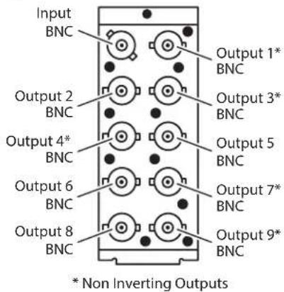
Figure 4. Rear View of OG-3GDA-1x9 Card Connectors
Inverted and Non-Inverted Outputs
Five of the outputs (1, 3, 4, 7, 9) are non-inverting. These are suitable for level-sensitive signaling, such as DVB-ASI. The other four outputs (2, 5, 6, 8) are identical, except inverted. All outputs are fully SDI compatible.
I/O Connections for OG-3GDA-2x4, Dual 1x4 Mode
Figure 5. Rear View of OG-3GDA-2x4 Card Connectors, Dual 1x4 Mode

Inverted and Non-Inverted Outputs
In Dual 1x4 Mode, four of the outputs (SDI 1 Out 2, SDI 1 Out 3, SDI 2 Out 2, SDI 2 Out 4) are non-inverting. These are suitable for level-sensitive signaling, such as DVB-ASI. The other four outputs (SDI 1 Out 1, SDI 1 Out 4, SDI 2 Out 1, SDI 2 Out 3) are identical, except inverted. All outputs are fully SDI compatible.
I/O Connections for OG-3GDA-2x4, Single 1x8 Mode
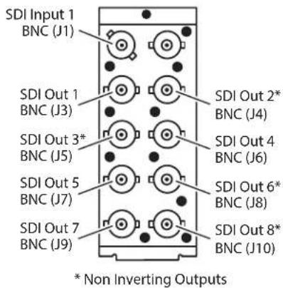
Figure 6. Rear View of OG-3GDA-2x4 Card Connectors, 1x8 Mode
Inverted and Non-Inverted Outputs
In 1x8 Mode, four of the outputs (SDI Out 2, SDI Out 3, SDI Out 6, SDI Out 8) are non-inverting. These are suitable for level-sensitive signaling, such as DVB-ASI. The other four outputs (1, 4, 5, 7) are identical, except inverted. All outputs are fully SDI compatible.
Card Alarm State – Red
This potential card state will result in a red alarm indicator:
- HW Status Unsupported Rear Module
Card Alarm State – Yellow
When the signal is either not present or is not locked, the Dashboard Control System shows a yellow Card State alarm: "Signal Status No Signal." Additionally, under the Input Status tab, the Signal Status is shown as "No Signal," and the Input Lock is shown as "No Lock."
Figure 7. Signal not present or not locked

Card Alarm State – Green
When there is a valid input signal detected, the Dashboard Control System shows a green Card State. Additionally, under the Input Status tab, the Signal Status is shown as "Signal Present," and the Input Lock is shown as "Locked." The detected Data Rate of the SDI Signal is also indicated (for example, "1.5 Gbps").
Figure 8. Signal is present and locked

User Controls
The OG-3GDA Series cards can be used right out of the box for many applications, since they are designed to recognize inputs and perform standard actions automatically. However, you can also remotely monitor the OG-3GDA Series through the Dashboard Control System for an openGear Frame.
Dashboard Control System
The Dashboard Control System, created by Ross Video, provides a control interface between Windows, macOS and Linux computers and the cards installed in an openGear frame. Dashboard operates through TCP/IP communication and requires an Ethernet connection between the controlling computer and an openGear frame.
For details about acquiring and using the Dashboard Control System, refer to "Using the Dashboard Control System" on page 15.
openGear and AJA
openGear is an open-architecture, modular frame system designed by Ross Video and supported by a diverse range of terminal equipment manufacturers, including AJA. Ross Video manufactures the frames, power supplies and network cards for openGear. AJA is a reseller of the openGear frames.
AJA Video is a leading manufacturer of video interface technologies, converters, digital video recording solutions and professional cameras, bringing high-quality, cost-effective products to the professional, broadcast and post-production markets. AJA products, including openGear cards, are designed and manufactured at our facilities in Grass Valley, California.
Installation
Summary
Installing an OG-3GDA Series card into an OG-X-FR openGear frame consists of the following steps:
- Install the Rear Panel onto the back of the frame corresponding to the slot pair you will be using for the OG-3GDA Series card.
- Insert the OG-3GDA Series card into the frame in the right (even numbered) slot of the pair.
- Connect the BNC cabling to the Rear Panel.

ESD Susceptibility - Static discharge can cause serious damage to sensitive semiconductor devices. Avoid handling circuit boards in high static environments such as carpeted areas, and when wearing synthetic fiber clothing. Always exercise proper grounding precautions when working on circuit boards and related equipment.
Unpacking
Unpack each openGear product you received from the shipping container and ensure that all items are included. If any items are missing or damaged, contact your sales representative or AJA directly.
Parts List
Quantity Description
1 OG-3GDA Series Front Card in ESD bag
1 10 BNC Rear Card
Rear OG-3GDA Series Card Installation
- Ensure that the frame is properly installed.
- Locate the card frame slot on the rear of the openGear frame into which you wish to install the openGear card.
NOTE: An OG-3GDA Series card occupies two slots in the frame.
-
Using a Phillips screwdriver, unscrew the top screw from the desired blank rear plate and remove the rear plate.
-
Seat the bottom of the Rear Card in the seating slot at the base of the frame back plane.
Figure 9. Rear Card Inserting Into Frame Seating Slot

natural_image
Close-up of an electronic device showing a multi-pin connector and internal circuit board (no visible text or symbols)- Align the top screw of the Rear Card with the screw hole on the top edge of the frame back plane.
- Ensure the Rear Card aligns with the desired card slot before tightening the screw.
- Using a Phillips screwdriver, fasten the Rear Card to the frame back plane. Do not over tighten.
Figure 10. Rear Card Inserted Into Frame Seating Slot

natural_image
Close-up of a metallic electronic circuit board with multiple cylindrical connectors inserted into a green PCB (no visible text or symbols)-
Ensure proper frame cooling and ventilation by having all rear frame slots covered with rear modules or blank metal plates if plates are not pre-installed.
-
Open the openGear frame door as follows:
A. Gently pull the side door tabs towards the center of the door, releasing the door from the frame.
B. Using both hands, pull the door towards you. The door extender arms prevent the door from falling.
-
Locate the Rear Card you installed as described above. The interior slot number is dependent on the slot combinations into which you installed the Rear Card. This allows adequate spacing to avoid damaging the card, the cards installed in the neighboring slots, or both.
-
Hold the card by the edges and carefully align the card edges with the rails inside the frame. The slots are numbered starting from the left-most slot when facing the frame front.
IMPORTANT: OG-3GDA Series cards are installed into the right (even numbered) slot of the pair in order to connect with the rear panel.
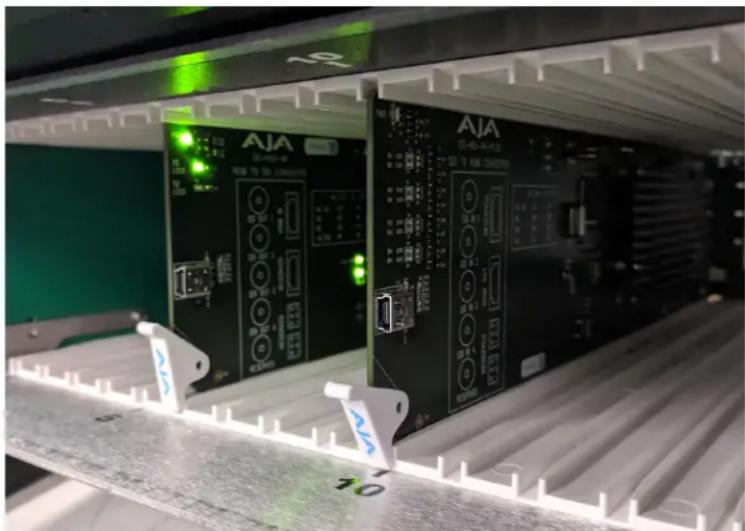
- Fully insert the card into the frame until the card is properly seated in the Rear Card. There are two stages to inserting the card:
A. After you feel the card's first click, its position in the frame will resemble the photograph below in Figure 11.
B. Next, press against the white plastic tab again until you feel the second click. The card's position will resemble the photograph below in Figure 12.
NOTE: Some cards require more pressure than others to be fully inserted. Make sure that the plastic tab at the bottom of the front edge of the card is completely upright. If it is tilting forward, the card is not yet fully inserted.
Figure 11. The card on the left is already fully inserted. The card on the right is not yet fully inserted, as indicated by the white plastic tab tilting forward.
natural_image
Two industrial control panels labeled 'AIA' with green indicator lights and control buttons, mounted on a metal shelf (no readable text or symbols)Figure 12. The white plastic tab for the card on the right is now upright. Both cards are shown fully inserted.

natural_image
Two AJA industrial control panels with green-lit indicators and labeled ports, mounted on a metal rack (no readable text or symbols)- Close the frame door as follows:
A. Slide the door into the frame.
B. Pull and release the door tabs to ensure the frame door is securely locked to the frame.
Cabling
Refer to "I/O Connections for OG-3GDA-1x9" on page 7, "I/O Connections for OG-3GDA-2x4, Dual 1x4 Mode" on page 8, and "I/O Connections for OG-3GDA-2x4, Single 1x8 Mode" on page 8 to identify the input and output signal connectors.
Using the Dashboard Control System
The Dashboard Control System is available as a free download from the openGear Dashboard Software Download webpage:
https://www.opengear.tv/frame-and-control/control-system/download/
Ross Video offers comprehensive documentation that covers the extensive capabilities of the Dashboard Control System:
https://www.rossvideo.com/support/product-documentation/dashboard/
This AJA OG-3GDA Series manual addresses only those essential aspects of the Dashboard Control System needed to control the OG-3GDA Series card.
Requirements
The Dashboard Control System requires the following components:
- openGear frame with a Frame Controller card
- Ethernet connection between the controlling computer and the openGear frame
NOTE: The openGear frame ships from AJA with the MFC-8322-S Frame Controller card for controlling the new AJA Dashboard cards. The openGear frame also supports the MFC-0G3-N Advanced Networking Frame Controller card, which can be used to control compatible OG cards.
Dashboard automatically discovers openGear and Dashboard Connect devices, such as openGear frames and cards that are present and accessible on your network.
Configuration Settings Stored in OG Card
Configuration settings made through DashBoard are stored in the OG-3GDA Series unit through subsequent power cycles.
Control Interface Basic Components
The basic components of the Dashboard Control System user interface consist of the basic tree view of frames and cards, the card information and status panel, and the parameter controls panel. These elements are shown below.
Figure 13. Main Sections of the Dashboard User Interface

Basic Tree View of Frames and Cards
The basic tree view in the left column shows the frames and cards that are discoverable by Dashboard on your network.
Card Information and Status
The card information and status panel, shown in the middle panel, display the basic status of the card currently selected in Dashboard. The yellow fields in this panel indicate that they are read-only.
Parameter Controls
The parameter controls panel on the right side of Dashboard shows the tabs and parameters that are configurable for the selected card. The white fields indicate that they can be written to, or modified.
Figure 14. OG-3GDA-2x4 Card Tab Screen in Dashboard

The Card tab screen indicates the basic information about the card itself such as the card name, hardware status, serial number, software version and other items.
Figure 15. OG-3GDA Series Input Status Tab Screen, Dual 2x4 Mode, in Dashboard
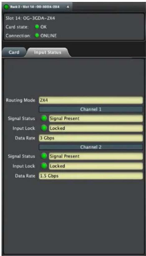
For Channels 1 and 2, as applicable, the Input Status fields report the Routing Mode (1x8 or 2x4), the Signal Status, the Input Lock Status, and the Data Rate.
Figure 16. OG-3GDA Series Input Status Tab Screen, Single 1x8 Mode, in Dashboard

The Input Status fields report the Routing Mode (1x8 or 2x4), the Signal Status, the Input Lock Status, and the Data Rate.
Figure 17. OG-3GDA Series Setup Tab Screen in Dashboard

Click on the Setup tab to view and make changes to the card name or to restore card settings to factory default values.
Card Name - By default, this field is pre-populated with the card name OG-3GDA-2x4 or OG-3GDA-1x9. You can change the card name by editing the text in the Card Name field.
NOTE: Changing the Card Name in the Setup tab also changes the name of the card in the Dashboard tree view.
Factory Settings - If you would like to revert the card settings to factory default values, click Restore.
Uploading New Software
When available, you can upload updated software to the OG-3GDA Series through the Dashboard Control System by following the steps below.
To Upload New Software
- Check the AJA website for new software for your OG-3GDA Series. If new software is found, download it and uncompress the file archive (zip).
- Click the Upload button in the lower panel of the Dashboard Control System to open the Upload Software Wizard.
Figure 18. OG-3GDA Series Upload Software Wizard window in Dashboard

- From the Upload Software Wizard window, select Browse.
- Navigate to the location of the downloaded .bin file containing the software update. Select the .bin file, then select Open. The Upload Software Wizard window displays characteristics of the selected file for uploading.
- Click Finish. The uploading process begins.
Figure 19. OG-3GDA-2x4 Uploading to Selected Devices window in Dashboard
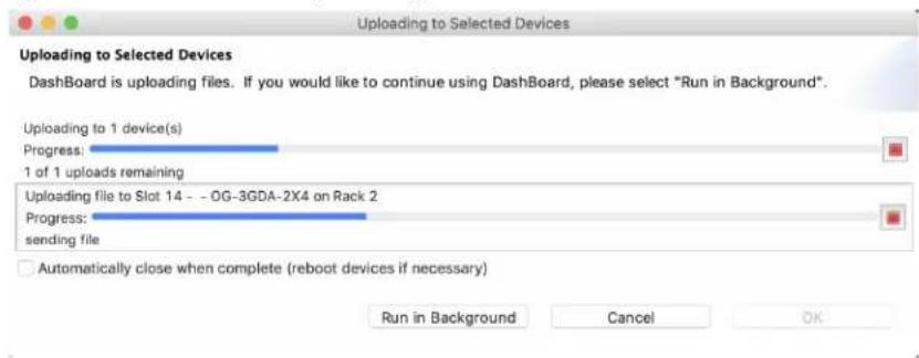
- When the progress bar indicates that the uploading is finished and status indicates "Complete," click OK.
- To verify the version of software or firmware currently installed on your card, select the Card tab from the center panel of Dashboard.
Figure 20. OG-3GDA Series Card Tab Screen in Dashboard indicating the currently installed software version.

Rebooting
Rebooting is a standard function built in to the Dashboard Control System, and should only be performed if the board has become unresponsive.
WARNING: During a reboot, any card operations will be briefly interrupted, but will be restored once the reboot has completed.
To Reboot the OG-3GDA Series
- Click the Reboot button in the lower panel of Dashboard. The reboot confirmation message displays.
Figure 21. Reboot confirmation window

- Click Yes. The message "Loading data, please wait. Refreshing device data" displays for a moment. The card will be offline for a few seconds, and any current operations will be interrupted.
Figure 22. The OG-3GDA Series briefly pauses operations while rebooting

- Following a Reboot operation, the board configuration will return to the settings that were in place at the time of rebooting.
OG-3GDA-1x9
Video Formats
• 150 Mbps - 3 Gbps, format agnostic
Video Input Digital
• 1 x 3G-SDI BNC, SMPTE-259/292/424
Video Output Digital
• 9 x 3G-SDI BNC, SMPTE-259/292/424
- 5 outputs noninverting
Cable Equalization
(Belden 1694A coax)
• 270 Mbps, 350m
• 1.5 Gbps, 200m
- 3 Gbps, 120m
Reclocking
• 270 Mbps, 1.483 Gbps, 1.485 Gbps, 2.966 Gbps, 2.970 Gbps - Auto Select
- All other rates are passed through and not reclocked
User Controls
- openGear Dashboard network control software via Windows, macOS or Linux
Size
- openGear standard form factor, front slot and rear card. Two slots required for each card.
Weight
• 0.5 lb (0.3 kg)
Power
- openGear frame compatible, 2.5 watts max per card
Environment
- Safe Operating Temperature Range: 0C to 40C (32F to 104F)
- Safe Storage Temperature Range (power OFF):-40C to 60C (-40F to 140F)
- Operating Relative Humidity :10-90% noncondensing
- Operating Altitude: <3,000m (<10,000ft)
OG-3GDA-2x4
Video Formats
• 150 Mbps - 3 Gbps, format agnostic
Video Input Digital
• 1 x 3G-SDI BNC (1x8 mode), SMPTE-259/292/424
• 2 x 3G-SDI BNC (2x4 mode), SMPTE-259/292/424
Video Output Digital
• 8 x 3G-SDI BNC, SMPTE-259/292/424
• 4 outputs noninverting (1x8 mode)
• 2 outputs noninverting for each DA (2x4 mode)
Cable Equalization
(Belden 1694A coax)
• 270 Mbps, 350m
• 1.5 Gbps, 200m
• 3 Gbps, 120m
Reclocking
• 270 Mbps, 1.483 Gbps, 1.485 Gbps, 2.966 Gbps, 2.970 Gbps - Auto Select
- All other rates are passed through and not reclocked
User Controls
- openGear Dashboard network control software via Windows, macOS or Linux
Size
- openGear standard form factor, front slot and rear card. Two slots required for each card.
Weight
• 0.5 lb (0.3 kg)
Power
- openGear frame compatible, 2.6 watts max per card
Environment
- Safe Operating Temperature: 0 to 40 degrees C (32 to 104 degrees F)
- Safe Storage Temperature (Power OFF): -40 to 60 degrees C (-40 to 140 degrees F)
- Operating Relative Humidity: 10-90% noncondensing
- Operating Altitude: <3,000 meters (<10,000 feet)
Appendix B – Safety and Compliance
Federal Communications Commission (FCC) Compliance Notices
Class A Interference Statement
This equipment has been tested and found to comply with the limits for a Class A digital device, pursuant to Part 15, Subpart B of the FCC Rules. These limits are designed to provide reasonable protection against harmful interference in a residential installation. This equipment generates, uses, and can radiate radio frequency energy and, if not installed and used in accordance with the instructions, may cause harmful interference to radio communications. However, there is no guarantee that interference will not occur in a particular installation. If this equipment does cause harmful interference to radio or television reception, which can be determined by turning the equipment off and on, the user is encouraged to try to correct the interference by one or more of the following measures:
- Reorient or relocate the receiving antenna.
- Increase the separation between the equipment and receiver.
- Connect the equipment into an outlet on a circuit different from that to which the receiver is connected.
- Consult the dealer or an experienced radio/TV technician for help.
FCC Caution
This device complies with Part 15 of the FCC Rules. Operation is subject to the following two conditions: (1) This device may not cause harmful interference, and (2) this device must accept any interference received, including interference that may cause undesired operation.
Canadian ICES Statement
Canadian Department of Communications Radio Interference Regulations
This digital apparatus does not exceed the Class A limits for radio-noise emissions from a digital apparatus as set out in the Radio Interference Regulations of the Canadian Department of Communications. This Class A digital apparatus complies with Canadian ICES-003.
European Union and European Free Trade Association (EFTA) Regulatory Compliance
This equipment may be operated in the countries that comprise the member countries of the European Union and the European Free Trade Association. These countries, listed in the following paragraph, are referred to as The European Community throughout this document:
AUSTRIA, BELGIUM, BULGARIA, CYPRUS, CZECH REPUBLIC, DENMARK, ESTONIA, FINLAND, FRANCE, GERMANY, GREECE, HUNGARY, IRELAND, ITALY, LATVIA, LITHUANIA, LUXEMBOURG, MALTA, NETHERLANDS, POLAND, PORTUGAL, ROMANIA, SLOVAKIA, SLOVENIA, SPAIN, SWEDEN, UNITED KINGDOM, ICELAND, LICHTENSTEIN, NORWAY, SWITZERLAND
Marking by this symbol indicates compliance with the Essential Requirements of the EMC Directive of the European Union 2014/30/EU.

This equipment meets the following conformance standards:
Safety
EN 60065: 2014 (T-Mark License),
IEC 60065: 2014 (CB Scheme Report/Certificate)
Additional licenses issued for specific countries available on request.
Emissions
EN 55032: 2012 + AC: 2013, CISPR 32: 2015, EN 61000-3-2: 2014, EN 61000-3-3: 2013
Immunity
EN 55103-2: 2009, EN 61000-4-2:2009, EN 61000-4-3: 2006 + A1:2008 + A2:2010,
EN 61000-4-4: 2004 + A1:2010, EN 61000-4-5:2006, EN 61000-4-6:2009,
EN 61000-4-11:2004
Environments: E2, E3 and E4
The product is also licensed for additional country specific standards as required for the International Marketplace

Warning! This is a Class A product. In a domestic environment, this product may cause radio interference, in which case, the user may be required to take appropriate measures.
This symbol on the product or its packaging indicates that this product must not be disposed of with your other household waste. Instead, it is your responsibility to dispose of your waste equipment by handing it over to a designated collection point for the recycling of waste electrical and electronic equipment. The separate collection and recycling of your waste equipment at the time of disposal will help conserve natural resources and ensure that it is recycled in a manner that protects human health and the environment. For more information about where you can drop off your waste for recycling, please contact your local authority, or where you purchased your product.
Korea KCC Compliance Statement
A급 기 기
(업무용 방송통신기자제)
(Broadcasting Communication Equipment for Office Use)
As an electromagnetic wave equipment for office use (Class A), this equipment is intended to use in other than home area. Sellers or users need to take note of this.
Taiwan Compliance Statement
警告使用者:
This is a Class A product based on the standard of the Bureau of Standards, Metrology and Inspection (BSMI) CNS 13438, Class A. In a domestic environment this product may cause radio interference in which case the user may be required to take adequate measures.
Japanese Compliance Statement
This is a Class A product based on the standard of the VCCI Council (VCCI 32: 2016). If this equipment is used in a domestic environment, radio interference may occur, in which case, the user may be required to take corrective actions.
Translated Warning and Caution Messages
The following caution statements, warning conventions, and warning messages apply to this product and manual.

Warning Symbol

Hazard Symbol

Caution Symbol
Before Operation Please Read These Instructions

Warning! Read and follow all warning notices and instructions marked on the product or included in the documentation.
Warning! Do not use this device near water and clean only with a dry cloth.
Warning! Do not block any ventilation openings. Install in accordance with the manufacturer's instructions.
Warning! Do not install near any heat sources such as radiators, heat registers, stoves, or other apparatus (including amplifiers) that produce heat.
Warning! Refer all servicing to qualified service personnel. Servicing is required when the device has been damaged in any way, such as power-supply cord or plug is damaged, liquid has been spilled or objects have fallen into the device, the device has been exposed to rain or moisture, does not operate normally, or has been dropped.
Warning! Disconnect the external AC power supply line cord(s) from the mains power before moving the unit.
Hazard! High Voltage. This situation or condition can cause injury due to electric shock.
Warning! Only use attachments and accessories specified and/or sold by the manufacturer.
Warning! Do not defeat the safety purpose of the polarized or grounding-type plug. A polarized plug has two blades with one wider than the other. A grounding type plug has two blades and a third grounding prong. The wide blade or the third prong are provided for your safety. If the provided plug does not fit into your outlet, consult an electrician for replacement of the obsolete outlet.
Warning! Since the Mains plug is used as the disconnection for the device, it must remain readily accessible and operable.
Warning! Protect the power cord from being walked on or pinched particularly at plugs, convenience receptacles, and the point where they exit from the device.
Warning! Unplug this device during lightning storms or when unused for long periods of time.
Warning! Ensure Mains Power is disconnected before installing the OG-3GDA Series modules into the frame, or installing and removing options. If a Mains switch is not provided, the power cord(s) of this equipment provide the means of disconnection. The socket outlet must be installed near the equipment and must be easily accessible.
Warning! Dual Power Cord Notice—please read this. To reduce the risk of electrical shock, disconnect both power cords before servicing equipment.
Caution! The OG-X-FR front fan door is heavy. Remove with Caution.
Warning! Do not open the chassis. There are no user-serviceable parts inside. Opening the chassis will void the warranty unless performed by an AJA service center or licensed facility.
Caution! To meet safety regulations for leakage current, connect the dual power supplies to separate branch circuits.
Warranty and Liability Information
Limited Warranty on Hardware
AJA Video Systems, Inc. (AJA Video) warrants that the hardware product, not including software components, will be free from defects in materials and workmanship for a period of five years from the date of purchase. AJA Video provides a separate software warranty as part of the license agreement applicable to software components.
If the Customer brings a valid claim under this limited warranty for a hardware product (hereafter, a "product") during the applicable warranty period, AJA Video will, at its sole option and as the Customer's sole remedy for breach of the above warranty, provide one of the following remedies:
- Repair or facilitate the repair the product within a reasonable period of time, free of charge for parts and labor.
- Replace the product with a direct replacement or with a product that performs substantially the same function as the original product.
- Issue a refund of the original purchase price less depreciation to be determined based on the age of the product at the time remedy is sought under this limited warranty.
To obtain service under this warranty, the Customer must notify AJA Video of the defect before expiration of the warranty period and make suitable arrangements for the performance of service by contacting AJA Video support through the channels set forth on the support contacts web page at https://www.aja.com/support. Except as stated, the Customer shall bear all shipping, packing, insurance and other costs, excluding parts and labor, to effectuate repair. Customer shall pack and ship the defective product to a service center designated by AJA Video, with shipping charges prepaid. AJA Video shall pay to return the product to Customer, but only if to a location within the country in which the AJA Video service center is located. SOME JURISDICTIONS DO NOT ALLOW THE EXCLUSION OF IMPLIED WARRANTIES OR LIMITATIONS ON APPLICABLE STATUTORY RIGHTS OF A CONSUMER, SO SOME OR ALL OF THE TERMS OF THIS PARAGRAPH MAY NOT APPLY TO YOU.
Limitation of Liability
Under no circumstances shall AJA video BE LIABLE IN ANY WAY FOR ANY LOST, CORRUPTED OR DESTROYED DATA, FOOTAGE OR WORK, OR FOR ANY OTHER INDIRECT, SPECIAL, INCIDENTAL OR CONSEQUENTIAL DAMAGES OR LOST PROFITS, OR FOR ANY THIRD PARTY CLAIM, IN CONNECTION WITH THE PRODUCT, WHETHER RESULTING FROM DEFECTS IN THE PRODUCT, SOFTWARE OR HARDWARE FAILURE, OR ANY OTHER CAUSE WHATSOEVER, EVEN IF AJA VIDEO HAS BEEN ADVISED OF THE POSSIBILITY OF SUCH DAMAGES. AJA VIDEO'S LIABILITY IN CONNECTION WITH THE PRODUCT SHALL UNDER NO CIRCUMSTANCES EXCEED THE PURCHASE PRICE PAID FOR THE PRODUCT. The foregoing limitations apply even if any remedy set forth in this LIMITED WARRANTY fails of its essential purpose. SOME JURISDICTIONS DO NOT ALLOW THE LIMITATION OF LIABILITY FOR PERSONAL INJURY, OR OF INCIDENTAL OR CONSEQUENTIAL DAMAGES, SO SOME OR ALL OF THE TERMS OF THIS PARAGRAPH MAY NOT APPLY TO YOU.
Governing Law and Language; Your Rights
This limited warranty is the only warranty provided by AJA Video on the hardware product. It supersedes all prior or contemporaneous understandings regarding such subject matter. No amendment to or modification of this warranty will be binding unless in writing and signed by AJA Video. The laws of the State of California, USA will govern this warranty and any dispute arising from it. Any translation of this
Agreement is intended for convenience and to meet local requirements and in the event of a dispute between the English and any non-English versions, the English version of this warranty will govern. This limited warranty gives you specific legal rights and you may have other rights that vary from jurisdiction to jurisdiction, some of which are noted above.
A
AJA Support 2
C
Configuration Settings Stored in OG cards 15
D
Dashboard Control System 11
Card Tab Screen 17
Control Interface Basic Components 15
Documentation 15
Downloading 15
Input Status Tab Screen
Dual 2x4 Mode 18
Single 1x8 Mode 19
Rebooting 22
Requirements 15
Uploading New Software 20
Using 15
Diagram
Simplified Block 6
F
Features 4
|
Installation 11
Cabling 14
Front Card Installation 13
Rear Card Installation 12
I/O Connections
for OG-3GDA-2X4 8
for OG-3GDA-2x4, 1x8 Mode 8
O
openGear and AJA 11
Overview 4
S
Setup Tab Screen 20
Signal Indicators
Dashboard Control System 9
T
Technical Support 2
U
User Controls 10
W
Warranty 35
- OG-3GDA Series openGear Cards
- Installation and Operation Guide
- Trademarks
- Copyright
- Contacting AJA Support
- Contents
- Chapter 1 – Introduction
- Card Overview
- Features
- OG-3GDA-1x9
- OG-3GDA-2x4
- Dual 1x4 Mode
- Single 1x8 Mode
- LED Indicators
- For OG-3GDA-1x9
- For OG-3GDA-2x4
- Block Diagram for OG-3GDA-2x4 in Dual 1x4 Mode
- Block Diagram for OG-3GDA-2x4 in Single 1x8 Mode
- I/O Connections for OG-3GDA-1x9
- Inverted and Non-Inverted Outputs
- I/O Connections for OG-3GDA-2x4, Dual 1x4 Mode
- I/O Connections for OG-3GDA-2x4, Single 1x8 Mode
- Card Alarm State – Red
- Card Alarm State – Yellow
- Card Alarm State – Green
- User Controls
- Dashboard Control System
- openGear and AJA
- Installation
- Summary
- Unpacking
- Parts List
- Rear OG-3GDA Series Card Installation
- Cabling
- Using the Dashboard Control System
- Requirements
- Configuration Settings Stored in OG Card
- Control Interface Basic Components
- Basic Tree View of Frames and Cards
- Card Information and Status
- Parameter Controls
- Uploading New Software
- To Upload New Software
- Rebooting
- To Reboot the OG-3GDA Series
- Video Formats
- Video Input Digital
- Video Output Digital
- Cable Equalization
- Reclocking
- Size
- Weight
- Power
- Environment
- Appendix B – Safety and Compliance
- Federal Communications Commission (FCC) Compliance Notices
- Class A Interference Statement
- FCC Caution
- Canadian ICES Statement
- European Union and European Free Trade Association (EFTA) Regulatory Compliance
- Korea KCC Compliance Statement
- Taiwan Compliance Statement
- 警告使用者:
- Japanese Compliance Statement
- Translated Warning and Caution Messages
- Before Operation Please Read These Instructions
- Warranty and Liability Information
- Limited Warranty on Hardware
- Limitation of Liability
- Governing Law and Language; Your Rights
- A
- C
- D
- F
- |
- O
- S
- T
- U
- W
Brand : AJA
Model : OG-3GDA-2X4
Category : Receiver