
EVU-TK60 - Uncategorized ELECTRO-VOICE - Free user manual and instructions
Find the device manual for free EVU-TK60 ELECTRO-VOICE in PDF.


| Product Type | Passive PA Loudspeaker |
| Brand | Electro-Voice |
| Model | EVU-TK60 |
| Dimensions (H x W x D) | 450 x 250 x 250 mm |
| Weight | 10.0 kg |
| Power Handling (RMS) | 60 W |
| Power Handling (Program) | 120 W |
| Frequency Response | 50 Hz - 20 kHz (-10 dB) |
| Sensitivity (1W/1m) | 90 dB |
| Impedance | 8 Ω |
| Input Connectors | XLR & 1/4" combo jack |
| Output Connectors | Speakon |
| Enclosure Material | Plywood with black polyurethane coating |
| Grille Material | Powder-coated steel |
| Mounting Options | Pole mount (35 mm), fly points (M8) |
| Application | Live sound, installed sound, portable PA |
| Color | Black |
| Included Accessories | None (speaker only) |
| Warranty | 5 years limited |
| Protection | Overload protection via dynamic driver protection |
| Operating Temperature | -10°C to 50°C |
| Certifications | CE, RoHS |
Frequently Asked Questions - EVU-TK60 ELECTRO-VOICE
User questions about EVU-TK60 ELECTRO-VOICE
0 question about this device. Answer the ones you know or ask your own.
Ask a new question about this device
Download the instructions for your Uncategorized in PDF format for free! Find your manual EVU-TK60 - ELECTRO-VOICE and take your electronic device back in hand. On this page are published all the documents necessary for the use of your device. EVU-TK60 by ELECTRO-VOICE.
USER MANUAL EVU-TK60 ELECTRO-VOICE
natural_image
Four line drawings of a speaker chamber with two speakers and three speakers, shown from different angles (no text or labels)EVU-1062/95
EVU-1082/95
EVU-2062/95
EVU-2082/95
Live For Sound
www.electrovoice.com

Table
of
Contents
INTRODUCTION 7
Introduction 7
Electro-Voice Model Number Notation 8
Optional Accessories 10
Dimensions 10
EVU-1062 Dimensions 10
EVU-1062 Block Diagram 10
EVU-1082 Dimensions 11
EVU-1082 Block Diagram 11
EVU-2062 Dimensions 12
EVU-2062 Block Diagram 12
EVU-2082 Dimensions 13
EVU-2082 Block Diagram 13
Tool List 13
Parts List 14
INSTALLATION 15
Digital Signal Processing 15
Preparing the EVU for Installation 16
Rotation of the High-Frequency Waveguide Sub Assembly 16
Connecting the Loudspeaker to the Signal Wires 17
Troubleshooting 17
EVU Rigging 18
Universal U-Bracket 18
Mounting the Universal U-Bracket to the Wall 21
Optional Omnimount Bracket 22
Optional M8 Forged, Shoulder-Style Closed Eyebolt 23
WORKING LOAD LIMITS AND SAFETY NOTICES 25
Working Load Limit and Safety-Factor Definitions 25
Electro-Voice WLL 25
Factor of Safety 25
System Working Load Limit Using EV Universal U-Bracket 26
Enclosure Working Load Limit Using Omnimount Bracket Attachment 26
Enclosure Working Load Limit for M8 Forged, Shoulder-Style Closed Eyebolt Attachment 26
Disclaimer 26
List
of
Figures
FIGURE 1. Available EVU Systems 9
FIGURE 2. Dimensions and Center of Gravity for the EVU-1062 10
FIGURE 3. EVU-1062 Block Diagram 10
FIGURE 4. Dimensions and Center of Gravity for the EVU-1082 ...... 11
FIGURE 5. EVU-1082 Block Diagram ....11
FIGURE 6. Dimensions and Center of Gravity for the EVU-2062 12
FIGURE 7. EVU-2062 Bock Diagram 12
FIGURE 8. Dimensions and Center of Gravity for the EVU-2082 ...... 13
FIGURE 9. EVU-2082 Block Diagram 13
FIGURE 10. EVU Series Part List 14
FIGURE 11. High-Frequency Waveguide Sub Assembly Orientation .... 16
FIGURE 12. Universal U-Bracket Assembly 19
FIGURE 13. EVU-1062 Assembly—Example ....20
FIGURE 14. Universal U-Bracket Mounting Holes 21
FIGURE 15. Bolt Pattern for 30 Series Single Cabinet 22
FIGURE 16. Bolt Pattern for 60 Series Double Cabinet 22
FIGURE 17. Eyebolt Orientation 24
WARNING:
Suspending any object is potentially dangerous and should only be attempted by individuals who have a thorough knowledge of the techniques and regulations of suspending objects overhead. Electro-Voice strongly recommends all loudspeakers be suspended taking into account all current national, federal, state, and local laws and regulations. It is the responsibility of the installer to ensure all loudspeakers are safely installed in accordance with all such requirements. When loudspeakers are suspended, Electro-Voice strongly recommends the system be inspected at least once per year or as laws and regulations require. If any sign of weakness or damage is detected, remedial action should be taken immediately. The user is responsible for making sure the wall, ceiling or structure is capable of supporting all objects suspended overhead. any hardware used to suspend a loudspeaker not associated with Electro-Voice is the responsibility of others.
Introduction
The Electro-Voice EVU series is a compact high power 2-way loudspeaker system used in a variety of applications where high-quality sound reinforcement is required in an ultra compact light-weight enclosure. The enclosure design utilizes asymmetrical angles to maintain tight clearances to wall and ceilings while providing optimal coverage patterns making it ideal to blend into surroundings.
This design is optimized for wall, stage lip and under balcony applications. The EVU series incorporates the ICT (Install Compact Transducer), a high-output 1.3-inch titanium compression driver coupled to a Constant Directivity* 90 x 50 rotatable waveguide. The EVU woofers are developed using FEA (Finite Element Analysis) optimization to provide the highest sensitivity while achieving the highest level of speech intelligibility.
The crossover designs uses 18dBper octave slopes with equalization for very smooth response in the vocal range, linear off-axis response and a protection circuit for long term reliability. The EVU line is constructed of multi-ply hardwood plywood enclosure with six (6) integral M8 suspension points to support a wide variety of mounting positions.
The EVU system is finished in textured paint available in either white or black. Each EVU system includes a universal U-Bracket to facilitate mounting. The U-Bracket provides for a 330^ unobstructed, translation of the loudspeaker. Additional mounting points are located on the back of the enclosure for use with an Omnimount* type bracket, available from Omnimount Inc. An available 60W transformer kit is easily mounted over the input panel for use in distributed systems.
An NL-4 cover plate accessory is available to simplify use as a portable system. All of these features give you the flexibility to address a large range of venues, quickly and precisely supporting customer requirements.
TABLE 1. Horn Pattern EVU Models
| Model Number Horn Pattern | |
| EVU-1062/95 90x50 | |
| EVU-1082/95 90x50 | |
| EVU-2062/95 90x50 | |
| EVU-2082/95 90x50 | |
Electro-Voice Model Number Notation
The Electro-Voice Model Number notation indicates the loudspeaker series, woofer quantity, woofer diameter, quantity of band passes in the system, and following a forward slash, the coverage pattern. An example using the EVU-1062/95 is shown in Table 2. The EVU-1062/95 uses a single ICT series 6.5 inch woofer in a two-way configuration and a 90^× 50^ pattern.
TABLE 2. Model Number Notation Description
| Model Number EVU-1062/95 | EVU - 1 06 2 / 95 | ||||||
| Description | Loudspeaker family/series | Number of Woofers | Woofer Diameter 6.5 inch | Number of Band Passes (Two-Way) | Coverage Pattern (90x50) |
Typical EVU systems are shown in Figure 18, with key dimensions, suspension points, weights and centers-of-gravity. Engineering data sheets for each model, containing full specifications and dimensional drawings, are shipped with each loudspeaker and can be downloaded from the Electro-Voice website, see www.electrovoice.com.
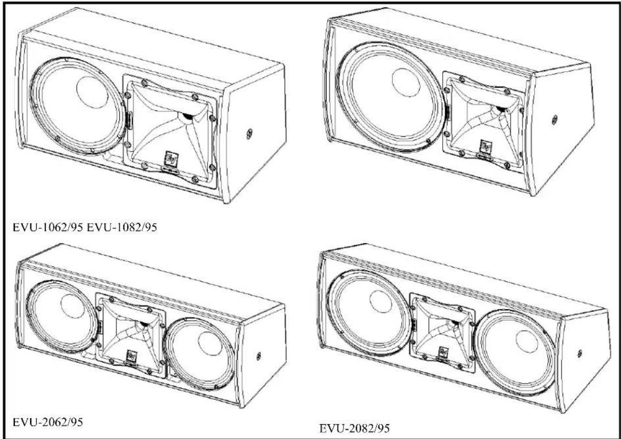
FIGURE 18. Available EVU Systems
Optional Accessories
| Item Description Ordering Information |
| NL4 Cover Plate Kit Dual NL4 Input Panel Cover EVU-CDNL4Transformer Kit 60 Watt Transformer Kit (70.7/100-V) EVU-TK60 |
Dimensions
EVU-1062 Dimensions
![14.556" [369.72mm] 8.205" [208.40mm] 4.900" [124.48mm] 3.550" [90.17mm] 5.714" [145.14mm] 2.000" [50.80mm] 1.863" [47.33mm] 4.250" [107.95mm] 1.591" [40.40mm] 8.138" [206.70mm] 6.750" [171.45mm] ● = CENTER OF GRAVITY EVU-1062](/content/2026/05/986423/images/0bcdeba5e0454ef13eedba50e2a28b55b1dda2fb1ad8e46c354be48b3721c5f7.jpg)
FIGURE 19. Dimensions and Center of Gravity for the EVU-1062
EVU-1062 Block Diagram
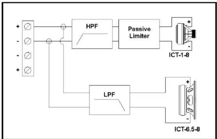
flowchart
graph TD
    A["Input Terminal"] --> B["HPF"]
    B --> C["Passive Limiter"]
    C --> D["ICT-1-8"]
    B --> E["LPF"]
    E --> F["ICT-6.5-8"]
    C --> G["Output"]
    style A fill:#f9f,stroke:#333
    style D fill:#ccf,stroke:#333
    style F fill:#cfc,stroke:#333
FIGURE 20. EVU-1062 Block Diagram
EVU-1082 Dimensions
![16.106" [409.10mm]](/content/2026/05/986423/images/f66c77491a03de140668c9c4d2102fd58efb611fb14f6579c72bf6a6dfb427fb.jpg)
![9.735" [247.23mm] 4.350" [110 49mm] 5.600" [142.24mm] 5.292" [134 42mm]](/content/2026/05/986423/images/aa044a63f777460746d825ff1aacb2533ba19bceab4faad357f6b456c7fdf226.jpg)
![2.000" [50.80mm] 1.860" [41.92mm] 4.260" [107.95mm] 2.091" [53.10mm]](/content/2026/05/986423/images/1c790e3ac25cf8237de231eba80d9a722b551f567ce5dafcd5d788bbbabf612a.jpg)
![9.339" [237.21mm] 7.500" [190.50mm]](/content/2026/05/986423/images/29897680f53246d501935d1f464d9d1a8ae295094004554e90453377583723a9.jpg)
EVU-1082
FIGURE 21. Dimensions and Center of Gravity for the EVU-1082
EVU-1082 Block Diagram
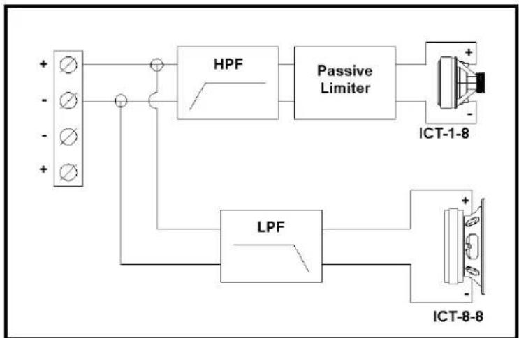
flowchart
graph TD
    A["Input Terminal"] --> B["HPF"]
    B --> C["Passive Limiter"]
    C --> D["ICT-1-8"]
    A --> E["LPF"]
    E --> F["ICT-8-8"]
    C --> G["Output"]
    style A fill:#f9f,stroke:#333
    style D fill:#ccf,stroke:#333
    style F fill:#cfc,stroke:#333
FIGURE 22. EVU-1082 Block Diagram
EVU-2062 Dimensions
![20.981' [652.92mm]](/content/2026/05/986423/images/f6bd12dcd2e291a21957b0f642740ad7953d8c04f264752ec5a701ac9a09c56e.jpg)
![8.205" [208.49mm] 4.300" [124.48mm] 3.650" [90.17mm] 5.714" [145.14mm]](/content/2026/05/986423/images/adb58d4f64328443f5174c86843d8572e8e28efa61dc6ec60f83a5758cf1caec.jpg)
![2.790° [39.85mm] 1.466° [37.80mm] 5.000° [127.00mm] 5.491° [139.46mm]](/content/2026/05/986423/images/309187db066507ab21c73ad1af097cdeb2f65ce5fd7b3041135fbf20d476dcfa.jpg)
![8 138" [206.70mm] 10.250" [260.35mm]](/content/2026/05/986423/images/8be8b184b95fde04d35f083cddd30ab000381b9749df4c400692cb1c988cfc2c.jpg)
EVU-2062
FIGURE 23. Dimensions and Center of Gravity for the EVU-2062
EVU-2062 Block Diagram
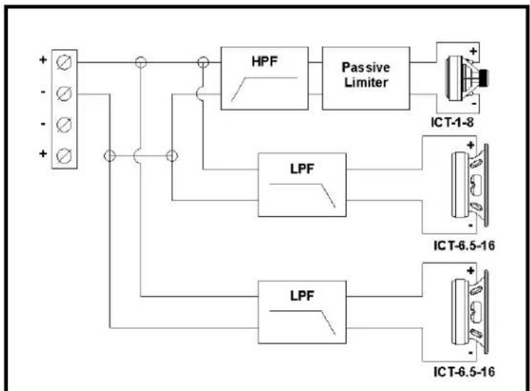
flowchart
graph TD
    A["Input"] --> B["HPF"]
    B --> C["Passive Limiter"]
    C --> D["ICT-1-8"]
    B --> E["LPF"]
    E --> F["ICT-6.5-16"]
    E --> G["LPF"]
    G --> H["ICT-6.5-16"]
FIGURE 24. EVU-2062 Bock Diagram
EVU-2082 Dimensions
![24.23" [615.47mm]](/content/2026/05/986423/images/34fb1f9912b7d1034d1078eb85aec2741288c9de08bffcda89c77d9707be0d6e.jpg)
![9.731" [247.23mm] 6.800" [42.24mm] 4.350" [110.49mm] 5.292" [134.42mm]](/content/2026/05/986423/images/e1fe227fc9776bf3a5b247af37a7ac6260ea2cded65f29c46726016132fd9669.jpg)
![2.781" [70.14mm] 1.275" [32.36mm] 5.000" [127.00mm] 7.118" [190.74mm]](/content/2026/05/986423/images/dd4f543b594b94e2ebb981fb4d7b67e9f005cca491637d793c353364337cefe5.jpg)
![9.330" [237.21mm] 11.750" [299.45mm]](/content/2026/05/986423/images/ec1320e2c4c4aa629bb08aa2f5e7d8155d8c71f438c52d87481eb7d9c8f5176b.jpg)
EVU-2082
FIGURE 25. Dimensions and Center of Gravity for the EVU-2082
EVU-2082 Block Diagram
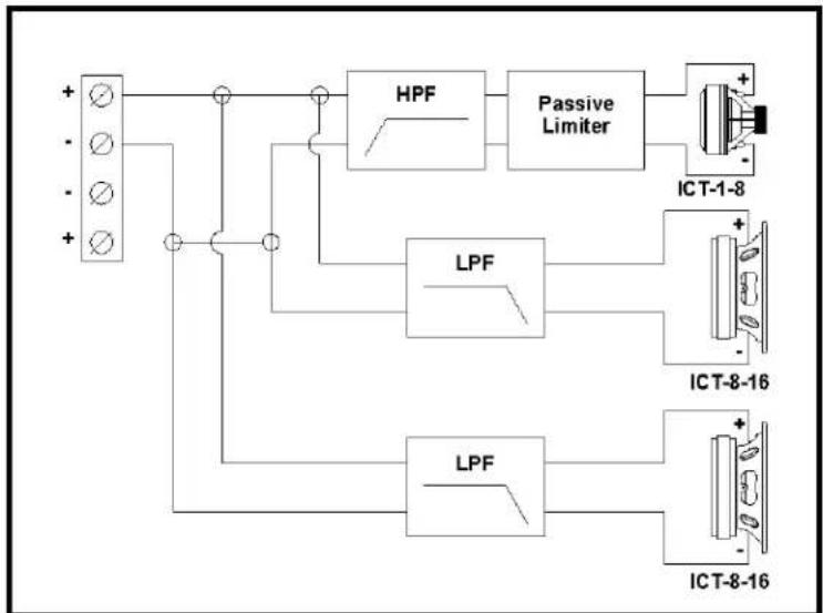
flowchart
graph TD
    A["Input Terminal"] --> B["HPF"]
    B --> C["Passive Limiter"]
    C --> D["ICT-1-8"]
    B --> E["LPF"]
    E --> F["ICT-8-16"]
    E --> G["LPF"]
    G --> H["ICT-8-16"]
FIGURE 26. EVU-2082 Block Diagram
Tool List
The tools required to prepare the EVU system for installation are as follows:
3/16-inch flat blade screwdriver
Phillips #2 screwdriver
NOTE: This screwdriver is also required to install the optional transformer kit or NL4 cover plate. For more information, see "Optional Accessories" on page 10.
Parts List
The EVU loudspeaker shipment includes the following:
- Loudspeaker (A) 1 each
• U-Bracket Sections (B) 2 each
• M8 Pan Head Bolts (C) 4 each
●M5 Pan Head Bolts (not shown) 4 each
• M5 Nuts (not shown) 4 each
•Rubber Washers (D) 2 each
•EDS Sheet (not shown) 1 each - User Manual (not shown) 1 each
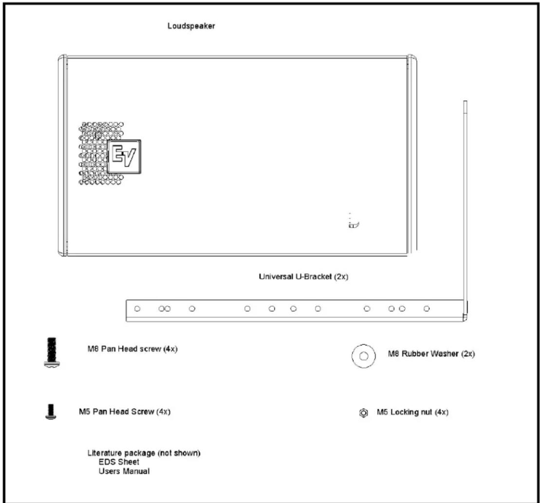
FIGURE 27. EVU Series Part List
Digital Signal Processing
For full-range passive systems, the internal crossover/equalizer network sends low frequencies to the woofer and high frequencies to the compression-driver/waveguide combination. In addition, the network tailors the frequency response and levels of each individual driver so the overall frequency response of the loudspeaker is essentially flat over its design operating range.
Once the EVU systems is installed in its venue, a DSP (Digital Signal Processor) is used to adjust the in-room frequency response, based on the specifics of the venue. In addition, the DSP should be used to provide the high-pass filters recommended to protect the EVU system against overdrive at frequencies below their operating range, failure to do so could damage the low-frequency drivers if fed high-level signals below the system's operating range. The recommended high-pass filter frequencies for infrasonic protection of EVU system is shown in Table 3.
TABLE 3. Recommended High-Pass Filter Frequencies
| Model Number Recommended High-Pass Frequency (minimum) |
| EVU-1062/95 90 Hz; 24 dB Per Octave |
| EVU-1082/95 90 Hz; 24 dB Per Octave |
| EVU-2062/95 90 Hz; 24 dB Per Octave |
| EVU-2082/95 90 Hz; 24 dB Per Octave |
Preparing the EVU for Installation
Rotation of the High-Frequency Waveguide Sub Assembly
All high-frequency waveguide sub assemblies have their horizontal and vertical patterns molded on the front of the waveguide for easy identification of orientation. The high-frequency waveguide sub assembly can be rotated to change the high frequency pattern.
NOTE: The high-frequency waveguide sub assembly is installed at the factory with the 90° wave pattern oriented along the long axis of the enclosure for all models.
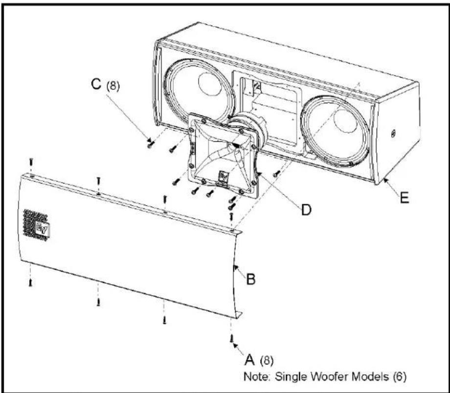
FIGURE 28. High-Frequency Waveguide Sub Assembly Orientation
To change the high-frequency waveguide sub assembly's orientation, do the following:
Tools:#2 Phillips screwdriver
- Remove the eight (8) screws (A) from the top and bottom of the grille.
NOTE: The grilles on the single woofer models, EVU-1062 and EVU-1082, use six (6) screws.
-
Remove the grille (B).
-
Remove the eight (8) screws (C) holding the high-frequency waveguide sub assembly.
-
Rotate the high-frequency waveguide sub assembly 90^ (D) until the desired pattern ( 90^ or 50^ ) marking is located along the long axis of the enclosure.
-
Reinstall the high-frequency waveguide sub assembly (D) with eight (8) screws (C).
-
Reattach the grille (B) to the front of the loudspeaker (E).
Connecting the Loudspeaker to the Signal Wires
To connect the signal wires to the connector on the back of the loudspeaker, do the following:
NOTE: This procedure is not illustrated.
Tools: 3/16-inch flat blade screwdriver
- Loosen the + and - screws.
- Attach the signal wires to the appropriate + and - terminal positions on the connector.
NOTE: Attach only one (1) signal wire per terminal.
- Tighten the + and - screws until the signal wire is secure.
Troubleshooting
| Problem Possible Cause Action | ||
| No Sound Amplifier Connect a known working test | loudspeaker to the amplifier outputs. If there is no sound, check that all the electronics are on, the signal routing is correct, the source is active, the volume is turned up, and so on. Correct/repair/replace as necessary. If there is sound, the problem is in the wiring. | |
| Wiring Verify you have co | connected the correct wire pairs to the amplifier.Play audio at a low level through the amplifier (for example, from a CD player or tuner). Connect the test loudspeaker in parallel with the malfunctioning line. If the sound level has gone or is very weak, the line has a short in it (possibly a severe scrape, pinch, or staple puncture). If the sound level is normal, the wire is open (possibly a cut wire or a missed connection). Observe proper polarity and use the test loudspeaker to move down the line and test each connection/junction until you find the problem and correct it. | |
| Intermittent output such as crackling or distortion | Faulty Connection Check | all connections at amplifier and speakers to ensure they are all clean and tight. If the problem persists, it may be in the amplifier or wiring. See Problem 1 above. |
| Constant noise such as buzzing, hissing or, humming | Defective amplifiers or other electronic device | If the noise is present but no audio is playing, the likely cause is the signal chain in the electronics. Evaluate each component as necessary to isolate the problem. |
| Poor system grounding or ground loop | Check and correct the system grounding, as required. | |
| If these suggestions do not solve your problem, contact your nearest Electro-Voice dealer or Electro-Voice distributor. | ||
EVU Rigging
All EVU loudspeaker systems incorporate heavy-duty M8 threaded accessory attachment points inside each enclosure. These attachment points allow the user to install single systems in horizontal and vertical configurations. The universal U-Bracket allows for installation in horizontal or vertical configurations with the ability to position the loudspeaker at any angle up to 330^ of total rotation with the transformer kit accessory.
Accessory attachment points are used for the following:
•Universal U-Bracket
•M8 forged, shoulder-style closed eyebolts (not included)
- Omnimount bracket (available from Omnimount)
Universal U-Bracket
The Universal U-Bracket and hardware, designed to work with all EVU models, is used to mount the loudspeaker and is included with all EVU system shipments.
To assemble the U-Bracket, do the following:
Tools: #2 Phillips screwdriver
- Orient the two (2) bracket rails (A) for assembly.
- Using the diagram appropriate to your installation, insert four (4) M5 pan head screws (B) through the first and second bracket rails. See Figure 29.
NOTE: The EVU-2082 model's bracket assembly uses three (3) M5 pan head screws.
- Securely fasten the four (4) nuts (C).
NOTE: Bracket assembly for the EVU-2082 model uses three (3) nuts.
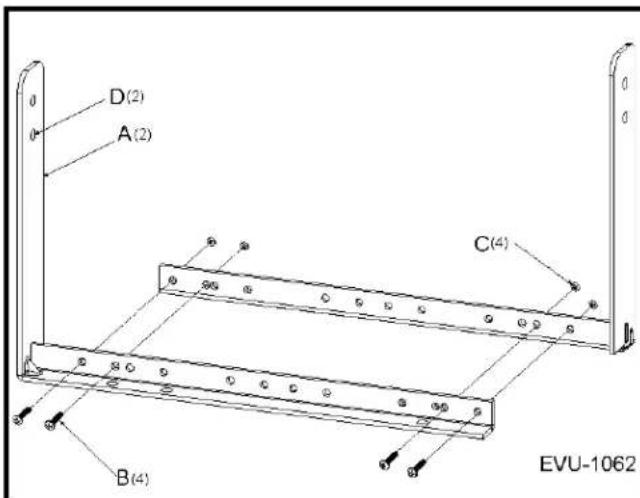
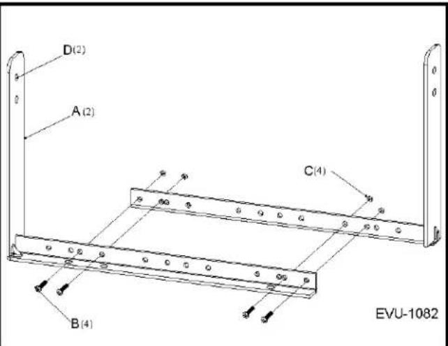

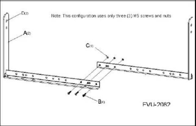
FIGURE 29. Universal U-Bracket Assembly
WARNING: The Universal U-Bracket is designed to hold the weight of one (1) loudspeaker. Never attempt to mount multiple loudspeakers to a single U-Bracket.
To install the assembled U-Bracket to the enclosure, do the following:
NOTE: All EVU systems are assembled in the following manner:
Tools: #2 Phillips screwdriver
- Remove two (2) M8 flat head screws (C) from each end of the loudspeaker enclosure (A).
- Position the loudspeaker enclosure inside the universal U-Bracket (B).
- Place one (1) M8 rubber washer (D) between the enclosure's screw hole and the universal U-Bracket on each side of the enclosure.
NOTE: See Figure 29 for holes specific to the system being mounted. - Securely fasten one (1) M8 panhead screw through the bracket, washer, and enclosure on each side of the assembly.
-
Position the loudspeaker at the desired angle.
-
Securely tighten the M8 flat head screw.
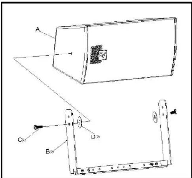
FIGURE 30. EVU-1062 Assembly—Example
Mounting the Universal U-Bracket to the Wall
The Universal U-Bracket is mounted to a wall using the holes provided in bottom rail. See Figure 31 for hole locations.
WARNING: Never under any circumstances mount the loudspeaker to a wall using wall anchors in drywall. Mounting to the structure is the responsibility of all others.
NOTE: For mounting to a wall, use two (2) 5/16-inch fasteners (recommended) or use two (2) 1/4-inch fasteners (minimum requirement) including two (2) washers. See Figure 29 for hole locations.
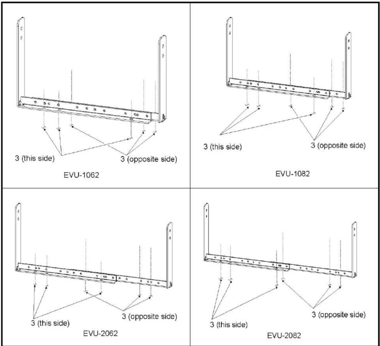
FIGURE 31. Universal U-Bracket Mounting Holes
Optional Omnimount Bracket
The Optional Omnimount Bracket, available from Omnimount, is used to facilitate mounting. The back panel of any of the EVU loudspeaker systems includes four (4) heavy-duty T-nut mounting points for an Omnimount style bracket. Four (4) M8 pan head Phillips screws are included in the EVU series hardware kit for mounting to an Omnimount bracket.
Compatible Omnimount Models
The following Omnimount models are available in 30 Series or 60 Series:
WA Series, WB Series, WBX Series, CA-MP Series, ST-MP Series, STX-MP Series.
See the Omnimount website as more models may become available.
When selecting your Omnimount bracket, ensure the Omnimount bracket's bolt pattern meets the pattern shown in Figure 32 for 30 series loudspeaker mounting or the pattern shown in Figure 33 for 60 Series single cabinet loudspeaker mounting.
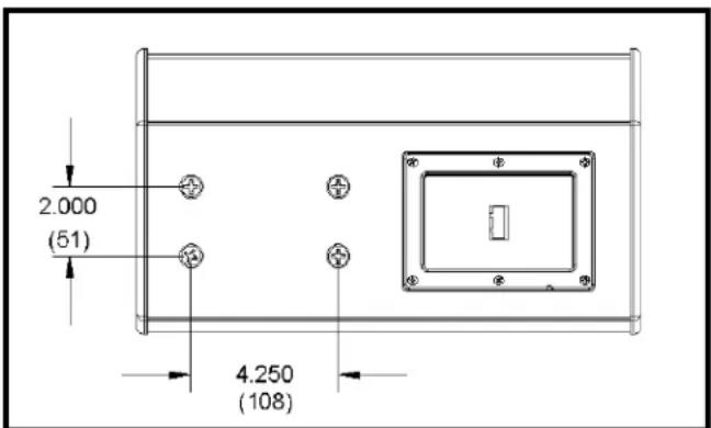
FIGURE 32. Bolt Pattern for 30 Series Single Cabinet
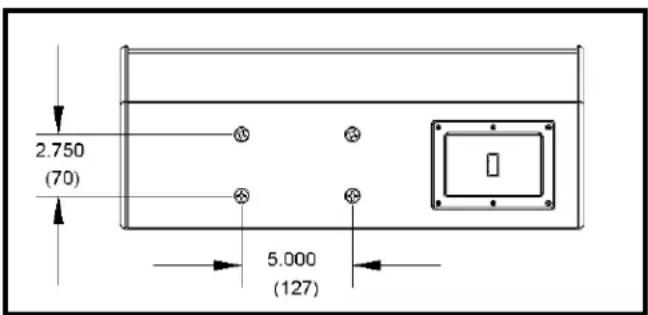
FIGURE 33. Bolt Pattern for 60 Series Double Cabinet
To install the optional Omnimount bracket to the enclosure, do the following:
NOTE: This procedure is not illustrated.
Tools:#2 Phillips screwdriver.
- Remove four (4) M8 flat head screws from the back of the loudspeaker enclosure.
- Position the optional Omnimount bracket over the bolt holes on the back of the enclosure.
- Apply thread locker (not included) to the four (4) M8 Pan head screws.
- Securely fasten the four (4) M8 pan head screws to the back of the enclosure and bracket.
REFERENCE: For more information, see the manufacturers's technical documentation to complete the installation.
- Set the desired angle.
Optional M8 Forged, Shoulder-Style Closed Eyebolt
The Optional M8 Forged, Shoulder-Style Closed eyebolt is used for rigging. Any of the six (6) heavy duty T-nut mounting points can be used for rigging with an M8 forged, shoulder-style closed eyebolt (purchased separately).
NOTE: Due to the counterbore on the enclosure, a fender style washer is required to assemble the eyebolt.
WARNING: Eyebolts used for rigging EVU loudspeaker systems in this manner must be made for rigging purposes i.e. forged shoulder-style closed design with a listed WLL (Working Load Limit) within the specifications called out in this manual.
WARNING: Only one (1) loudspeaker may be rigged with the optional eyebolt. The loudspeaker is not designed to hold the weight of additional cabinets, as with clusters.
To install the optional M8 forged, shoulder-style closed eyebolt to the case, do the following:
NOTE: This procedure is not illustrated.
Tools: #2 Phillips screwdriver.
Parts: M8 forged, shoulder-style closed eyebolt(s). Fender washer for each eyebolt.
NOTE: Fasten up to six (6) M8 eyebolts (four [4] on top and one [1] on each end) to the loudspeaker enclosure according to your mounting requirements.
- Remove any M8 flat head screws from positions you intend to install an M8 forged, shoulder-style closed eyebolt.
IMPORTANT: If only one (1) eyebolt is used to rig the loudspeaker, the installer must use a threadlocker to prevent the loudspeaker from spinning out of the eyebolt during operation.
-
Position the M8 fender washer(s) over the desired mounting point(s).
-
Apply threadlocker to the threads of the M8 forged, shoulder-style closed eyebolt(s), as recommended by the manufacturer.
-
Install the M8 forged shoulder-style closed eyebolt(s) to the case, ensuring the eyebolt is fully seated.
WARNING: Mounting to the structure is the responsibility of others.
IMPORTANT: Eyebolts must be fully seated and oriented in the plane of pull as shown in Figure 34. Always use washers to distribute suspension loads.
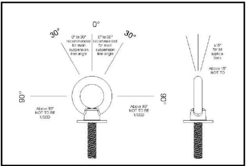
FIGURE 34. Eyebolt Orientation
Working Load Limits and Safety Notices
Working Load Limit and Safety-Factor Definitions
Electro-Voice WLL
The structural ratings for all of the EVU rigging components and complete loudspeaker systems are based on test results in which parts were stressed to failure (optional methods of rigging have not been tested by our facility). Manufacturers typically present the structural-strength ratings of mechanical components or systems as either the WLL or the ultimate-break strength. Electro-Voice chooses to present the structural-load ratings of the EVU loudspeaker systems as the WLL. The WLL rating represents the maximum load that can be applied to a mechanical component or system.
WARNING: The user should never apply loads that exceed the WLL of any of the rigging components or complete loudspeaker systems described in the manual.
Factor of Safety
The WLL for the EVU rigging components and complete loudspeaker systems described in this manual are based on a minimum 8:1 safety factor. The safety factor is defined as the ratio of the ultimate break strength divided by the WLL, where the ultimate break strength represents the force at which a part fails structurally.
For example, if a part has a WLL of 35 lb (15.8 kg), it would not structurally fail until a force of at least 280 lb (127 kg) was applied, based on an 8:1 safety factor.
WARNING: The user should never apply a load to that part that exceeds the value listed in this manual for these products. The safety factor provides a margin of safety above the WLL to accommodate normal dynamic loading and normal wear.
WARNING: For WLL and Safety Factors, the WLL defined by the manufacturer of any rigging component should never be exceeded. Electro-Voice bases the WLL of its EVU products on a minimum of an 8:1 safety factor. Other manufacturers of rigging components may base their WLL on safety factors other than 8:1. For example, 5:1 safety factors are fairly common among rigging manufacturers because many regulatory agencies call for a minimum safety factor of 5:1.
IMPORTANT:
When an EVU loudspeaker system is installed where local regulations only require a safety factor of 5:1, Electro-Voice insists that the WLL of the EVU rigging never be exceeded and that an 8:1 safety factor be maintained for the EVU loudspeakers.
The user is cautioned that some local regulations may require safety factors higher than 8:1. In that circumstance, Electro-Voice insists the user maintain the higher safety factor as required by the local regulations throughout the entire EVU installation. It is the responsibility of all others to make sure any EVU installation meets all applicable local, state or federal safety regulations.
System Working Load Limit Using EV Universal U-Bracket
| System WLL Using EV Universal U-Bracket | |
| Maximum Working Load Limit Maximum number of enclosures | |
| 35 lb (15.875 kg) 1 | |
Enclosure Working Load Limit Using Omnimount Bracket Attachment
| Enclosure WLL Using an Omnimounta Bracket Attachment | |
| Maximum Working Load Limit Maximum number of enclosures | |
| 35 lb (15.875 kg) 1 | |
a. Brackets supplied by other manufacturers using the same bolt pattern can be used to mount the EVU enclosure provided WLL are met.
For more information, see the manufacturer's data sheet for the bracket being considered.
WARNING: Do not, under any circumstances, attempt to mount more then one (1) loudspeaker in this manner.
Enclosure Working Load Limit for M8 Forged, Shoulder-Style Closed Eyebolt Attachment
| Enclosure WLL Using an M8 Forged, Shoulder-Style Closed Eyebolt | ||
| Maximum Working Load Limit | Maximum number of enclosures | Minimum number of suspension lines |
| 35 lb (15.875 kg) 1 1 | ||
For more information, see the manufacturer's data sheet for the M8 forged, shoulder-style closed eyebolt being considered.
WARNING: Ensure the eyebolt is designed for rigging. Never under any circumstances use an eyebolt that is not designed for rigging.
NOTE: Limitations for eyebolt installations are based primarily on the limitations of the loudspeaker enclosure and not necessarily the eyebolts data.
Disclaimer
All non-Electro-Voice hardware is the responsibility of all others.
- Table
- of
- Contents
- INTRODUCTION 7
- INSTALLATION 15
- WORKING LOAD LIMITS AND SAFETY NOTICES 25
- List
- Figures
- WARNING:
- Introduction
- Electro-Voice Model Number Notation
- Optional Accessories
- Dimensions
- EVU-1062 Dimensions
- EVU-1062 Block Diagram
- EVU-1082 Dimensions
- EVU-1082 Block Diagram
- EVU-2062 Dimensions
- EVU-2062 Block Diagram
- EVU-2082 Dimensions
- EVU-2082 Block Diagram
- Tool List
- Parts List
- Digital Signal Processing
- Preparing the EVU for Installation
- Rotation of the High-Frequency Waveguide Sub Assembly
- Connecting the Loudspeaker to the Signal Wires
- EVU Rigging
- Universal U-Bracket
- Mounting the Universal U-Bracket to the Wall
- Optional Omnimount Bracket
- Compatible Omnimount Models
- Optional M8 Forged, Shoulder-Style Closed Eyebolt
- Working Load Limits and Safety Notices
- Working Load Limit and Safety-Factor Definitions
- Electro-Voice WLL
- Factor of Safety
- IMPORTANT:
- Disclaimer
Brand : ELECTRO-VOICE
Model : EVU-TK60
Category : Uncategorized