Bandpass BPS6 - Subwoofer SONANCE - Free user manual and instructions
Find the device manual for free Bandpass BPS6 SONANCE in PDF.


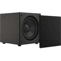
| Product Type | In-wall/Outdoor Bandpass Subwoofer |
| Brand | Sonance |
| Model | Bandpass BPS6 |
| Driver Size | 6.5 inches |
| Frequency Response | 35 Hz – 200 Hz |
| Power Handling (RMS) | 100 Watts |
| Impedance | 8 Ohms |
| Dimensions (H x W x D) | 12 x 12 x 6 inches |
| Weight | 10.5 lbs |
| Mounting Type | Flush-mount or surface-mount |
| Enclosure Type | Bandpass |
| Connector Type | Spring-loaded terminals |
| Weather Resistance | UV and moisture resistant |
| Recommended Amplifier Power | 50 – 150 Watts RMS |
| Warranty | 5 years limited |
| Installation | Secure with included screws |
| Maintenance | Wipe with damp cloth; avoid solvents |
| Safety | Keep away from water; do not overload |
| Spare Parts | Contact Sonance for replacements |
Frequently Asked Questions - Bandpass BPS6 SONANCE
User questions about Bandpass BPS6 SONANCE
0 question about this device. Answer the ones you know or ask your own.
Ask a new question about this device
Download the instructions for your Subwoofer in PDF format for free! Find your manual Bandpass BPS6 - SONANCE and take your electronic device back in hand. On this page are published all the documents necessary for the use of your device. Bandpass BPS6 by SONANCE.
USER MANUAL Bandpass BPS6 SONANCE
SONANCE ARCHITECTURAL SERIES®
AS BANDPASS STEREO SUBWOOFER QUICKSTART GUIDE BPS6

Box Contents
(1) Quickstart guide
(1) Bandpass subwoofer w/ port tube
(1) Cardboard mounting template
Mounting screws & washers:
(4) 5/16" x 2" lag screws (for thinner beams)
(4) 5/16" x 3" lag screws (for thicker beams)
(4) 5/16" washers
Bandpass subwoofer can be installed in joists spaced 16" on center or greater.
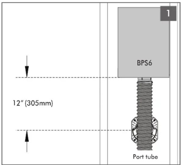
Determine the location for the mounting platform. Ensure there is adequate room for the BPS6 subwoofer at the location of the platform.
The speaker opening must be located within 12" (305mm) of the BPS6 to allow the port tube to reach through the platform.
natural_image
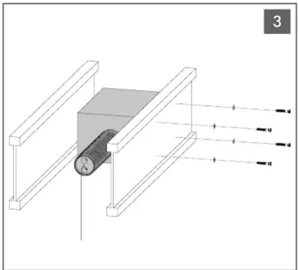
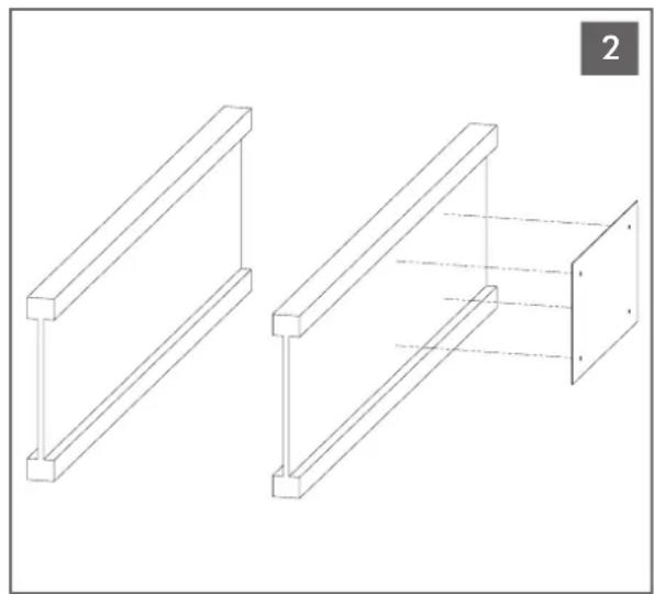
Technical diagram of a mechanical assembly with a threaded component and labeled components (no text or symbols present)Hold the side of the BPS6 with the rubber damping pad up against the side of the joist and install the four lag screws and washers to secure the BPS6 in place.
natural_image
Technical line drawing of two structural frame components with no text or symbolsPlace the mounting template on the side of the joist and drill four 1/2" (12.7mm) holes through the joist at the locations shown on the mounting template.
natural_image
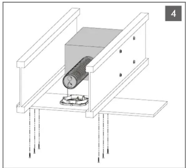
Technical diagram of a mechanical assembly with a bolt and mounting base (no text or symbols)Attach the mounting platform to the joists. See mounting platform quickstart guide or visit www.sonance.com/in-wall-in-ceiling/architectural-series for detailed installation manual.
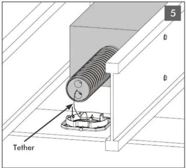
On the end of the BPS6 port tube there is a tether. The tether will be used later to guide the BPS6 port tube through the mounting platform opening.
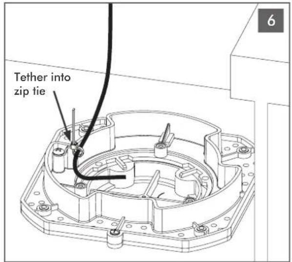
Position end of port tube as close as possible to back of mounting platform. Loop tether into the anchored zip tie and secure. This process ensures that bandpass connector is easily attached later and other tradespersons won't infringe on port tube assembly area.
natural_image
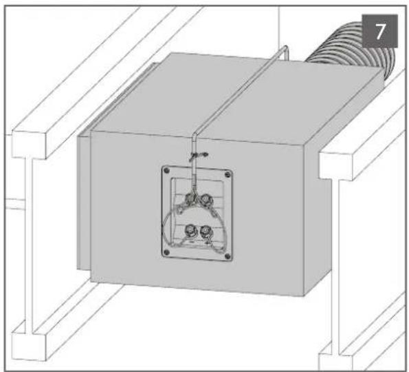
3D technical diagram of a mechanical assembly with a central component and threaded connection (no text or symbols)Secure the wires with a zip tie near the terminals to prevent accidental removal by another tradesperson.
natural_image
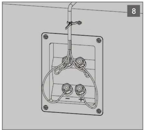
Technical line drawing of a mechanical or electrical component with no visible text, numbers, or symbols.Attach the four conductor wires from the amplifier to the input terminals on the end of the BPS6. Positive wires to red terminals and negative wires to black terminals. Run the speakers wires to amplifier location and run signal test with 9V battery. NOTE: Port tube contains foam plug with tether, make sure pressure levels don't expel the foam and tether. Do not connect the voice coils in parallel.

For wiring diagrams & detailed eManual scan the QR code or visit www.sonance.com/in-wall-in-ceiling/architectural-series

SONANCE®
©2014 Sonance. All rights reserved.
Sonance and Architectural Series are registered trademarks of Dana Innovations.
Due to continuous product improvement, all features and specifications are subject to change without notice.
For the latest Sonance product specification information, visit our website: www.sonance.com
SONANCE • 212 Avenida Fabricante • San Clemente, CA 92672-7531 USA
(800) 582-7777 or (949) 492-7777 • FAX: (949) 361-5151 • Technical Support: (800) 582-0772
www.sonance.com
Brand : SONANCE
Model : Bandpass BPS6
Category : Subwoofer