
AT-UHD-PRO3-1616M - Video switch Atlona - Free user manual and instructions
Find the device manual for free AT-UHD-PRO3-1616M Atlona in PDF.


| Product Type | 16x16 HDMI Matrix Switcher |
| Video Support | 4K UHD (3840x2160 @60Hz 4:4:4) |
| HDCP Compliance | HDCP 2.2/1.4 |
| Audio Support | Embedded HDMI audio up to 7.1 channels |
| Input/Output Ports | 16 HDMI inputs, 16 HDMI outputs |
| Control Interfaces | Ethernet, RS-232, IR, USB, Front Panel |
| EDID Management | Built-in EDID learning and emulation |
| Scaling | Integrated 4K scaling on outputs |
| Dimensions (W x D x H) | 17.3 x 19 x 3.5 inches (440 x 483 x 89 mm) |
| Weight | 10.5 kg (23.1 lbs) |
| Power Supply | 100-240V AC, 50/60 Hz, 100W max |
| Operating Temperature | 32°F to 104°F (0°C to 40°C) |
| Rack Mountable | Yes, 2U rack height |
| Maintenance | Wipe with a dry, soft cloth. Do not use liquids or solvents. |
| Safety Precautions | Ensure proper ventilation; do not block vents. Use supplied power cord only. |
| Spare Parts and Repair | Contact Atlona support for replacement parts and service. |
Frequently Asked Questions - AT-UHD-PRO3-1616M Atlona
User questions about AT-UHD-PRO3-1616M Atlona
0 question about this device. Answer the ones you know or ask your own.
Ask a new question about this device
Download the instructions for your Video switch in PDF format for free! Find your manual AT-UHD-PRO3-1616M - Atlona and take your electronic device back in hand. On this page are published all the documents necessary for the use of your device. AT-UHD-PRO3-1616M by Atlona.
USER MANUAL AT-UHD-PRO3-1616M Atlona
| Version Release Date Notes | ||
| 1 Nov 2018 | New format | |
| 2 Jul 2019 | Added missing IR remote control unit documentation | |
| 3 Feb 2020 | Added missing factory reset procedure | |
| 4 Jul 2020 | Removed IR remote control unit - no longer included | |
Welcome to Atlona!
Thank you for purchasing this Atlona product. We hope you enjoy it and will take a extra few moments to register your new purchase.
Registration only takes a few minutes and protects this product against theft or loss. In addition, you will receive notifications of product updates and firmware. Atlona product registration is voluntary and failure to register will not affect the product warranty.
To register your product, go to http://www.atlona.com/registration
Sales, Marketing, and Customer Support
Main Office
Atlona Incorporated
70 Daggett Drive
San Jose, CA 95134
United States
Office: +1.877.536.3976 (US Toll-free)
Office: +1.408.962.0515 (US/International)
Sales and Customer Service Hours
Monday - Friday: 6:00 a.m. - 4:30 p.m. (PST)
http://www.atlona.com/
International Headquarters
Atlona International AG
Ringstrasse 15a
8600 Dübendorf
Switzerland
Office: +41 43 508 4321
Sales and Customer Service Hours
Monday - Friday: 09:00 - 17:00 (UTC +1)
Operating Notes

IMPORTANT: Visit http://www.atlona.com/product/AT-UHD-PRO3-1616M for the latest firmware updates and User Manual.

IMPORTANT: This product will no longer include a handheld remote control beginning January, 2021. IR control codes for this product can be found in the Resources Tab in the document titled "IR Codes" or by clicking this link
Atlona, Inc. ("Atlona") Limited Product Warranty
Coverage
Atlona warrants its products will substantially perform to their published specifications and will be free from defects in materials and workmanship under normal use, conditions and service.
Under its Limited Product Warranty, Atlona, at its sole discretion, will either:
- repair or facilitate the repair of defective products within a reasonable period of time, restore products to their proper operating condition and return defective products free of any charge for necessary parts, labor and shipping.
OR
- replace and return, free of charge, any defective products with direct replacement or with similar products deemed by Atlona to perform substantially the same function as the original products.
OR
- refund the pro-rated value based on the remaining term of the warranty period, not to exceed MSRP, in cases where products are beyond repair and/or no direct or substantially similar replacement products exist.
Repair, replacement or refund of Atlona products is the purchaser's exclusive remedy and Atlona liability does not extend to any other damages, incidental, consequential or otherwise.
This Limited Product Warranty extends to the original end-user purchaser of Atlona products and is non-transferrable to any subsequent purchaser(s) or owner(s) of these products.
Coverage Periods
Atlona Limited Product Warranty Period begins on the date of purchase by the end-purchaser. The date contained on the end-purchaser 's sales or delivery receipt is the proof purchase date.
Limited Product Warranty Terms – New Products
• 10 years from proof of purchase date for hardware/electronics products purchased on or after June 1, 2013.
• 3 years from proof of purchase date for hardware/electronics products purchased before June 1, 2013.
• Lifetime Limited Product Warranty for all cable products.
Limited Product Warranty Terms - Refurbished (B-Stock) Products and Discontinued Products
- 3 years from proof of purchase date for all Refurbished (B-Stock) and Discontinued hardware and electronic products purchased on or after June 1, 2013.
Remedy
Atlona recommends that end-purchasers contact their authorized Atlona dealer or reseller from whom they purchased their products. Atlona can also be contacted directly. Visit atlona.com for Atlona's contact information and hours of operation. Atlona requires that a dated sales or delivery receipt from an authorized dealer, reseller or end-purchaser is provided before Atlona extends its warranty services. Additionally, a return merchandise authorization (RMA) and/or case number, is required to be obtained from Atlona in advance of returns.
Atlona requires that products returned are properly packed, preferably in the original carton, for shipping. Cartons not bearing a return authorization or case number will be refused. Atlona, at its sole discretion, reserves the right to reject any products received without advanced authorization. Authorizations can be requested by calling 1-877-536-3976 (US toll free) or 1-408-962-0515 (US/international) or via Atlona's website at atlona.com.
Exclusions
This Limited Product Warranty excludes:
- Damage, deterioration or malfunction caused by any alteration, modification, improper use, neglect, improper packaging or shipping (such claims must be presented to the carrier), lightning, power surges, or other acts of nature.
Atlona, Inc. ("Atlona") Limited Product Warranty
- Damage, deterioration or malfunction resulting from the installation or removal of this product from any installation, any unauthorized tampering with this product, any repairs attempted by anyone unauthorized by Atlona to make such repairs, or any other cause which does not relate directly to a defect in materials and/or workmanship of this product.
- Equipment enclosures, cables, power supplies, batteries, LCD displays, and any accessories used in conjunction with the product(s).
- Products purchased from unauthorized distributors, dealers, resellers, auction websites and similar unauthorized channels of distribution.
Disclaimers
This Limited Product Warranty does not imply that the electronic components contained within Atlona's products will not become obsolete nor does it imply Atlona products or their electronic components will remain compatible with any other current product, technology or any future products or technologies in which Atlona's products may be used in conjunction with. Atlona, at its sole discretion, reserves the right not to extend its warranty offering in instances arising outside its normal course of business including, but not limited to, damage inflicted to its products from acts of god.
Limitation on Liability
The maximum liability of Atlona under this limited product warranty shall not exceed the original Atlona MSRP for its products. To the maximum extent permitted by law, Atlona is not responsible for the direct, special, incidental or consequential damages resulting from any breach of warranty or condition, or under any other legal theory. Some countries, districts or states do not allow the exclusion or limitation of relief, special, incidental, consequential or indirect damages, or the limitation of liability to specified amounts, so the above limitations or exclusions may not apply to you.
Exclusive Remedy
To the maximum extent permitted by law, this limited product warranty and the remedies set forth above are exclusive and in lieu of all other warranties, remedies and conditions, whether oral or written, express or implied. To the maximum extent permitted by law, Atlona specifically disclaims all implied warranties, including, without limitation, warranties of merchantability and fitness for a particular purpose. If Atlona cannot lawfully disclaim or exclude implied warranties under applicable law, then all implied warranties covering its products including warranties of merchantability and fitness for a particular purpose, shall provide to its products under applicable law. If any product to which this limited warranty applies is a “Consumer Product” under the Magnuson-Moss Warranty Act (15 U.S.C.A. §2301, ET SEQ.) or other applicable law, the foregoing disclaimer of implied warranties shall not apply, and all implied warranties on its products, including warranties of merchantability and fitness for the particular purpose, shall apply as provided under applicable law.
Other Conditions
Atlona's Limited Product Warranty offering gives legal rights, and other rights may apply and vary from country to country or state to state. This limited warranty is void if (i) the label bearing the serial number of products have been removed or defaced, (ii) products are not purchased from an authorized Atlona dealer or reseller. A comprehensive list of Atlona's authorized distributors, dealers and resellers can be found at www.atlona.com.
Safety and Certification
CAUTION
RISK OF ELECTRIC SHOCK
DO NOT OPEN
CAUTION: TO REDUCT THE RISK OF
ELECTRIC SHOCK
DO NOT OPEN ENCLOSURE OR EXPOSE
TO RAIN OR MOISTURE.
NO USER-SERVICEABLE PARTS
INSIDE REFER SERVICING TO
QUALIFIED SERVICE PERSONNEL.

The exclamation point within an equilateral triangle is intended to alert the user to the presence of important operating and maintenance instructions in the literature accompanying the product.

The information bubble is intended to alert the user to helpful or optional operational instructions in the literature accompanying the product.
- Read these instructions.
- Keep these instructions.
- Heed all warnings.
- Follow all instructions.
- Do not use this product near water.
- Clean only with a dry cloth.
- Do not block any ventilation openings. Install in accordance with the manufacturer's instructions.
- Do not install or place this product near any heat sources such as radiators, heat registers, stoves, or other apparatus (including amplifiers) that produce heat.
-
Do not defeat the safety purpose of a polarized or grounding-type plug. A polarized plug has two blades with one wider than the other. A grounding type plug has two blades and a third grounding prong. The wide blade or the third prong are provided for your safety. If the provided plug does not fit into your outlet, consult an electrician for replacement of the obsolete outlet.
-
Protect the power cord from being walked on or pinched particularly at plugs, convenience receptacles, and the point where they exit from the product.
- Only use attachments/accessories specified by Atlona.
- To reduce the risk of electric shock and/or damage to this product, never handle or touch this unit or power cord if your hands are wet or damp. Do not expose this product to rain or moisture.
- Unplug this product during lightning storms or when unused for long periods of time.
- Refer all servicing to qualified service personnel. Servicing is required when the product has been damaged in any way, such as power-supply cord or plug is damaged, liquid has been spilled or objects have fallen into the product, the product has been exposed to rain or moisture, does not operate normally, or has been dropped.
- Unit is intended for installation in a restricted access location accessible by authorized personnel only.
- Unit is intended for installation in a location where children are not present.
- CAUTION: After plug disconnection, do not touch power plug pins or appliance inlet pins due to the presence of charged capacitors, which may cause electric shock.
-
Unit shall be connected only to earthed socket outlet.
-
Apparatets stikprop skal tilsluttes en stikkontakt med jord som giver forbindelse til stikproppens jord.
- Laite on liitettävä suojakoskettimilla varustettuun pistorasiaan.
- Apparatet må tilkoples jordet stikkontakt.
• Apparaten skall anslutas till jordat uttag.
CE


FCC Compliance
FCC Compliance and Advisory Statement: This hardware device complies with Part 15 of the FCC rules. Operation is subject to the following two conditions: 1) this device may not cause harmful interference, and 2) this device must accept any interference received including interference that may cause undesired operation. This equipment has been tested and found to comply with the limits for a Class A digital device, pursuant to Part 15 of the FCC Rules. These limits are designed to provide reasonable protection against harmful interference in a commercial installation. This equipment generates, uses, and can radiate radio frequency energy and, if not installed or used in accordance with the instructions, may cause harmful interference to radio communications. However there is no guarantee that interference will not occur in a particular installation. If this equipment does cause harmful interference to radio or television reception, which can be determined by turning the equipment off and on, the user is encouraged to try to correct the interference by one or more of the following measures: 1) reorient or relocate the receiving antenna; 2) increase the separation between the equipment and the receiver; 3) connect the equipment to an outlet on a circuit different from that to which the receiver is connected; 4) consult the dealer or an experienced radio/TV technician for help. Any changes or modifications not expressly approved by the party responsible for compliance could void the user's authority to operate the equipment. Where shielded interface cables have been provided with the product or specified additional components or accessories elsewhere defined to be used with the installation of the product, they must be used in order to ensure compliance with FCC regulations.
Copyright, Trademark, and Registration
© 2021 Atlona Inc. All rights reserved. "Atlona" and the Atlona logo are registered trademarks of Atlona Inc. Pricing, specifications and availability subject to change without notice. Actual products, product images, and online product images may vary from images shown here.

The terms HDMI, HDMI High-Definition Multimedia Interface, and the HDMI Logo are trademarks or registered trademarks of HDMI licensing Administrator, Inc.
Dolby, Dolby Atmos, and the double-D symbol are registered trademarks of Dolby Laboratories Licensing Corporation.
For DTS patents, see http://patents.dts.com. Manufactured under license from DTS, Inc. DTS, the Symbol, DTS and the Symbol together, and Digital Surround are registered trademarks and/or trademarks of DTS, Inc. in the United States and/or other countries. © DTS, Inc. All Rights Reserved.
All other trademark(s), copyright(s), and registered technologies mentioned in this document are the properties of their respective owner(s).
Table of Contents
Introduction 9
Features 9
Package Contents 9
Panel Description 10
Front 10
Rear 11
Installation 12
Audio Connectors 12
Connection Instructions 13
Setting the IP Mode 14
Connection Diagram 16
Basic Operation 17
Powering the Matrix 17
Standby Mode 18
Viewing Matrix Settings 19
Viewing the current routing state 19
Displaying the System Settings 20
Resetting to Factory Defaults 21
Routing Inputs to Outputs 22
Single Input-to-Output Routing 22
Routing a Single Input to All Outputs 24
Output Mirroring 26
Changing the Mirrored Port 26
Disabling Mirroring 28
Creating and Editing Routing Presets 30
Creating a Routing Preset 30
Recalling a Preset 31
Editing Presets 32
Renaming Presets 33
Input and Output Management 34
Renaming Inputs 34
Renaming Outputs 35
Renaming Memory Presets 36
EDID Management 37
Loading EDID Presets 37
Using the Front Panel 37
Using the web GUI 39
Copying a Downstream EDID 40
Managing Users 43
Adding Users 43
Editing / Deleting Users 45
Advanced Operation
RS-232 Control 46
Determining the Port Type 46
Cable Assembly 47
Pass-through mode 48
Control mode 50
IR Control 51
Cable Assembly 51
Controlling Display Devices 52
Controlling Headend Devices 53
The Web GUI 54
Introduction to the Web GUI 54
Status page 56
Table of Contents
Firmware page 57
Network page 58
Control page 59
Users page 60
I/O page 61
Route Memory page 62
EDID page 63
HDCP page 64
HDBT Test page 65
Audio page 66
Appendix
67
Updating the Firmware 67
Cable Termination 69
HDBaseT Testing 70
Default Settings 71
Mounting Instructions 72
Rack Installation 72
Surface Mounting 73
Specifications 74
Introduction
The AT-UHD-PRO3-1616M is a 4K/UHD 16×16 HDMI to HDBaseT Matrix Switcher with PoE for 4K/UHD @ 60 Hz video signals with Power over Ethernet for receivers and analog audio breakout. The matrix provides both extended distance, 330 foot (100 meter) and long distance, 230 foot (70 meter) HDBaseT transmission over category cable. It also provides convenient bidirectional extension of both RS-232 and IR Control. Four HDMI outputs are provided as mirrored outputs designed for routing HDMI-based audio to an AVR or as additional matrix outputs. The matrix switcher is HDCP 2.2 compliant and supports EDID communication. The matrix is control system-friendly and integrates with any TCP/IP, RS-232, or IR based control signals. Designed for multi-zone residential or commercial distribution applications, the PRO3-1616M features a 2U, rack-mountable enclosure with an internal, international power supply.
Features
- 16 HDBaseT outputs with dual-distance transmission of A/V, control and power signals over a single category cable
- Four HDMI outputs with independently selectable mirror and matrix modes
• 4K/UHD capability with HDCP 2.2 copy protection
• Power over Ethernet for remote-powered receivers
• Audio de-embedding with volume, mute, and five-band EQ
• TCP/IP, RS-232, and IR control - Easy, GUI-based configuration using integrated web server
• EDID management
• Multi-channel audio compliant
• Support for 192 kHz/24-bit digital audio - Independent volume control, mute and five-band EQ for each de-embedded audio output
- Integrated HDBaseT link status monitoring
- Quiet, active cooling
- Rack mountable 2U, full rack width enclosure with internal, international power supply
- Includes user manual, rack mount brackets, and detachable power cable
- Award-winning 10 year limited product warranty
Package Contents
1 x AT-UHD-PRO3-1616M
28 x 4-pin captive screw connectors
1 x 5-pin captive screw connector
1 x IEC power cable
2 x 19" mounting brackets
1 x Installation Guide
Panel Description
Front
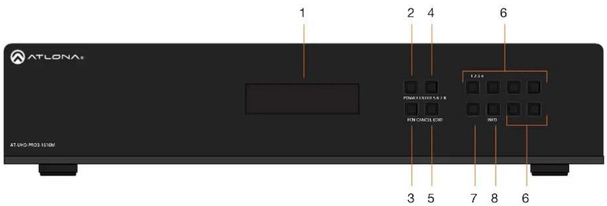
1 Front Panel Display
This 16-character, two-row display provides the status of the matrix during various operations.
2 POWER
Press this button to power-on or place the matrix in standby mode. The button is backlit to indicate the current state: When the matrix is powered, the button will be solid blue. In standby mode, the button will be red. Refer to Powering the Matrix (page 17) for more information.
3 FCN
Press this button to select the desired function. Refer to Displaying the System Settings (page 20) for more information.
4 ENTER
Press this button to confirm operations or view the current status for inputs. Refer to Routing Inputs to Outputs (page 10) for more information.
5 CANCEL
Press this button to abort the current operation, return to the previous menu, or go to the home screen. Refer to Routing Inputs to Outputs (page 10) for more information.
6 Routing / Function Buttons
Press these buttons to manage routing operations and other functions.
7 EDID
Press this button, in conjunction with the FNC button, to save and load EDID data. Refer to EDID Management (page 37) for more information.
8 INFO
Press this button to display the current firmware version, IP address, and MAC address of the matrix. Refer to Displaying the System Settings (page 20) for more information.
Rear

1 HDBaseT OUT
Connect up to 16 PoE-compatible receivers to these ports using Ethernet cable.
2 HDMI IN
Connect up to 16 HD/UHD source devices to these ports using HDMI cables.
3 HDMI OUT
Connect up to four HD/UHD source devices to these ports using HDMI cables.

NOTE: By default, HDMI OUT 17 - HDMI OUT 20 are used for mirroring: ZONE OUT 8 follows ZONE OUT 7 and ZONE OUT 10 follows ZONE OUT 9. These two HDMI output ports can also be configured to receive any one of eight HDMI input signals, allowing the unit to function as an 8 x 10 matrix switcher. Refer to Output Mirroring (page 26) for more information.
4 AUDIO OUT
Connect these ports to the analog inputs of a DSP, audio amplifier, or other output device, using the included 4-pin captive screw blocks. Refer to Audio Connectors (page 12) for wiring information.
5 IR IN
Connect a control system to these ports. Refer to IR Control (page 51) for more information.
6 IR OUT
Connect IR emitters to these ports, in order to control source devices. Refer to IR Control (page 51) for more information.
7 LAN
Connect an Ethernet cable from this port to the Local Area Network (LAN).
8 FW
Connect a USB to mini-USB cable from this port to the USB port on a computer, when performing a firmware upgrade. Refer to Updating the Firmware (page 67) for more information.
9 MAIN (RS-232 / IR IN)
Connect a control system to this port using the included 5-pin captive screw block. Control can be performed using either RS-232 or electrical IR. Refer to RS-232 Control (page 46) and IR Control (page 51) for more information.
10 ON/OFF
Press this button to power-on or power-off the matrix.
11 PWR 100-240VAC 50/60Hz
Connect the included power cable from this receptacle to an available AC power outlet.
Installation
Audio Connectors
The AUDIO IN and AUDIO OUT ports on the AT-UHD-PRO3-1616M provide analog inputs and outputs, respectively, for audio. Use the included 4-pin captive screw blocks to connect unbalanced analog sources/outputs.

natural_image
Green 3D model of a mechanical connector or terminal block with three circular slots (no text or symbols visible)
Connection Instructions
- Connect up to 16 HD/UHD sources to the HDMI IN (1 - 16) ports.
- Connect up to 16 PoE-compatible receivers (e.g. AT-UHD-EX-100CE-RX) to the HDBaseT OUT ports using Ethernet cables.

NOTE: Ports 1ED through 8ED are used for extended distance connections and are capable of extending up to 330 feet (100 meters). Ports 9 through 16 are limited to a maximum distance of 230 feet (70 meters).
-
Connect up to four HD/UHD displays to the HDMI OUT ports using HDMI cables. These ports can be used for receiving an input source or can be used for mirroring. Refer to Output Mirroring (page 26) for more information.
-
Connect an Ethernet cable from the LAN port to a Local Area Network (LAN). This step is required in order to access the Web GUI and/or use the matrix for IP control.
-
Connect the included power cable from the PWR 100-240VAC 50/60Hz power receptacle to an available AC power outlet.

OPTIONAL
- Connect a control system to the matrix using the MAIN RS-232 IR IN port. Both RS-232 and electrical IR are supported. Refer to RS-232 Control (page 46) and IR Control (page 51) for more information.
- Connect up to 12 audio output devices (e.g. AT-GAIN-60) to the AUDIO OUT (1 - 12) ports using the included 4-pin captive screw blocks. Refer to Audio Connectors (page 13) for wiring instructions.
- Connect a third-party control system to the IR IN (1 - 16) ports. IR will be transmitted over the HDBaseT OUT ports to control displays or other sink devices which are connected to the receiver endpoint. Refer to IR Control (page 51) for more information.
- Connect up to 16 IR emitters to the IR OUT ports, allowing IR control of source devices at the headend. Refer to and IR Control (page 51) for more information.
Setting the IP Mode
The AT-UHD-PRO3-1616M is shipped with DHCP enabled. Once connected to a network, the DHCP server (if available), will automatically assign an IP address to the unit. If no DHCP server is found or available, then the matrix will be set to the following IP settings:
Default IP settings
| Description | Setting |
| IP address | 192.168.0.150 |
| Netmask | 255.255.255.0 |
| Gateway | 192.168.0.1 |
The front-panel display can be used to identify the IP address of the matrix. The AT-UHD-PRO3-1616M can also be set to a static IP address, if necessary.
Using the Front Panel
- Make sure the home screen is displayed. If the home screen is not displayed, press the CANCEL button to return to the home screen.
- Press and release the FNC button to display the SELECT FUNCTION screen.

-
Press button 4 to display the IP mode screen.
-
IP DHCP
-
IP STATIC
-
Press button 2 to select IP Static mode. The matrix will display a prompt to confirm the selection.
IP STATIC ADDRESSING ENTER TO CONFIRM
- Press the ENTER button to confirm the selection. The matrix will reboot and will indicate that the IP change is taking place.
IP CHANGE TO STATIC REBOOTING SYSTEM...
Once the matrix completes the reboot process, it will display the home screen. When the matrix is set to static IP mode, the default IP address of 192.168.1.254 is used.
To place the matrix in DHCP mode, repeat the above steps and press button 2 when the IP mode screen is displayed.
Using the web GUI
- Login to the web GUI. Refer to Introduction to the Web GUI (page 54) for more information.
-
Click Network, under the Settings section in the menu bar on the left side of the screen.
-
Click ON, next to DHCP, to set the matrix to DHCP mode. If set to DHCP mode, the IP Address, Subnet, and Gateway fields will automatically be assigned by the DHCP server (if one exists). If no DHCP server can be found, the matrix will be assigned the static IP address of 192.168.0.150 with a subnet mask of 255.255.255.0.
- Click OFF to set the matrix to static IP mode. When set to static IP mode, enter the required information in the IP Address, Subnet, and Gateway fields, as shown in the illustration below.
Network Settings
IP Reset
System Secure (SSH)
ON

DHCP
ON

IP Address
10.0.1.106
Subnet
255.255.255.0
Gateway
10.0.1.1
Telnet Port
23
HTTP Port
80
IP Timout
300
Hostname
AT-UHD-PRO3-1616M-xxxxx
SDDP
Telnet Login Mode
ON

Save
Cancel
- Click the Save button to commit changes.
Connection Diagram

flowchart
graph TD
    A["AT-UHD-PRO3-1616M"] -->|Audio| B["Zone Amplifier"]
    A -->|H/O/Ret| C["AT-UHD-EX-100CE-RX"]
    A -->|H/O/Ret| D["A/V Receiver"]
    A -->|H/O/Ret| E["Media Player"]
    A -->|H/O/Ret| F["Control System"]
    A -->|C/Control| G["Blu-ray Player"]
    A -->|C/Control| H["Router"]
    A -->|C/Control| I["5.1 Speaker System"]
    B -->|Audio| J["Speaker"]
    B -->|Audio| K["HD display"]
    C -->|Cohort 34Hz| L["5.1 Speaker System"]
    D -->|Cohort 34Hz| L
    E -->|Cohort 34Hz| L
    F -->|Cohort 34Hz| L
    G -->|Cohort 34Hz| L
    H -->|Cohort 34Hz| L
Basic Operation
Powering the Matrix
The master power button is located on the rear panel of the matrix. This rocker switch allows power to be applied to the matrix.
- Press the ON/OFF button so that it is in the ON position. To power-off the matrix, push the button to the OFF position. During the power-on procedure, the backlight on the POWER button will flash blue/red. Once complete, the POWER button will be backlit with a solid blue light.

natural_image
Front view of a network switch device with multiple Ethernet ports and drive cables (no visible text or labels)
NOTE: If the matrix does not power, check to make sure that the power cable, on the rear of the unit, is connected to an active AC wall outlet. Also verify that the ON/OFF switch is in the ON position.

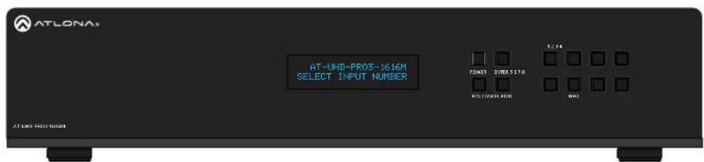
- The front panel display will indicate that the matrix is initializing. After a few moments the home screen will be displayed.

Initialization Screen Home Screen

- The matrix is now ready for operation.
Standby Mode
The POWER button on the front panel of the matrix, allows the matrix to be powered-on or placed in standby mode. In standby mode, the web GUI is still accessible, even though the unit appears "powered off".
-
Locate the POWER button on the front panel. When the matrix is in normal operating mode, the POWER button will be backlit by a solid blue light. In this mode, operations using the front panel buttons, web GUI, or through API commands can be performed.
-
Press the POWER button, on the front panel to place the matrix in standby mode.
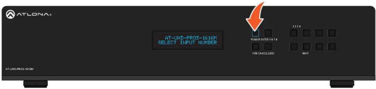
The matrix will power-down and be placed in a low-power state and the POWER button will be backlit by a solid red light.
When the matrix is in standby mode, operations using the front-panel buttons are suspended. However, access to the matrix, through the web GUI or API commands is still available.

- Press the POWER button again, to power-on the matrix and return to normal operating mode.

NOTE: Firmware version 16.1.00-2 supports a front-panel display time-out feature. If there is no front-panel activity after 30 seconds, the front-panel display will turn off. The time-out feature only hides the text in the front panel display. Initiating a routing command, for example, or other operation will turn on ("wake up") the front-panel display and the matrix will wait for the next command to be entered.
Viewing Matrix Settings
The front panel display provides the current status of the matrix and its settings. The buttons on the front panel can be used to display the current routing settings as well as network settings.
Viewing the current routing state
- Make sure the home screen is displayed. If the home screen is not displayed, press the CANCEL button to return to the home screen.
- Press the ENTER button to display the routing screen. The first six inputs and outputs will be displayed, indicating the current routing state.

By default, the AT-UHD-PRO3-1616M is set to a "one-to-one" routing state, meaning that each input is routed to its associated output: 1-to-1, 2-to-2, etc., as shown below. This matrix features a total of 16 HDMI inputs and 20 outputs (16 HDBaseT outputs and four HDMI outputs).

flowchart
graph TD
    A["Outputs (top row)"] --> B["Routing Screen"]
    C["Inputs (bottom row)"] --> B
    B --> D["1 2 3 4 5 6"]
- Press the ENTER button to two more times to display outputs 7 through 12, and then 13 through 18.

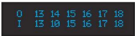
- Press the ENTER button again to display outputs 19 and 20
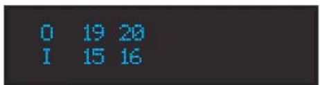
- Press the ENTER button once more to return to the home screen.
Displaying the System Settings
- Make sure the home screen is displayed. If the home screen is not displayed, press the CANCEL button to return to the home screen.
- Press and release the FNC button to display the SELECT FUNCTION screen.
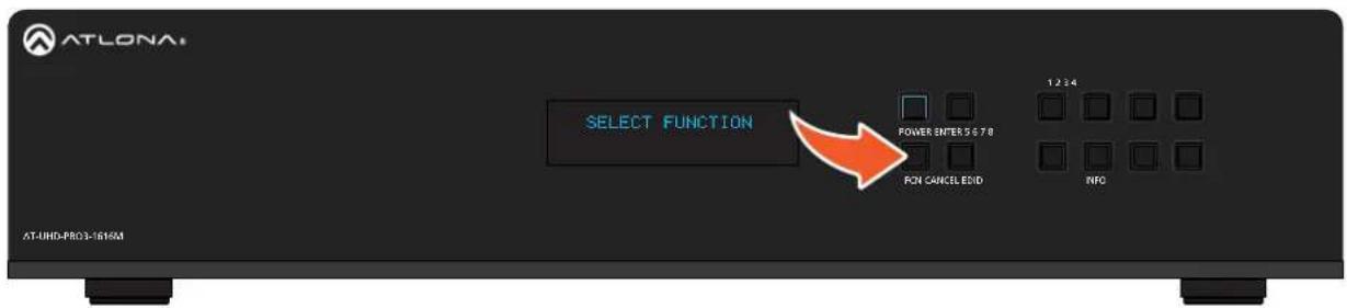
- Press and release the INFO button to display the firmware version.

- Consecutively press the INFO button to cycle through each of the following screens:

flowchart
graph TD
    A["IP ADDRESS\n010.000.001.066"] --> B["IP PORT\n23"]
    B --> C["MAC ADDRESS\nB8:98:B0:03:1A:77"]
    C --> A
- Press the CANCEL button to return to the home screen. If the CANCEL button is not pressed within 10 seconds, the matrix will automatically return to the home screen.
Resetting to Factory Defaults
The following procedure will reset the AT-UHD-PRO3-1616M to factory-default settings.
- Make sure the home screen is displayed. If the home screen is not displayed, press the CANCEL button to return to the home screen.
- Simultaneously press and hold the EDID and INFO button for five seconds.
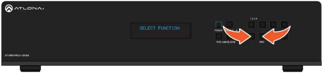
- Release both buttons.
Note that during the factory-reset process, the AT-UHD-PRO3-1616M will not show any signs of resetting. Wait an additional five seconds before after resetting the unit, before resuming normal operation.
Routing Inputs to Outputs
When the AT-UHD-PRO3-1616M is shipped from the factory, the matrix is set to "one-to-one" routing mode. This means that input 1 is routed to output 1, input 2 is routed to output 2, and so on. The following section describes how to change the routing state. When changing the routing state, the input is specified first, then the output.
The AT-UHD-PRO3-1616M can route individual inputs to outputs or can route a single input to all outputs, simultaneously.
Single Input-to-Output Routing
Using the Front Panel
- Make sure the home screen is displayed. If the home screen is not displayed, press the CANCEL button to return to the home screen.
- Press and release the desired input from the bank of numerical buttons on the front panel. In this example, HDMI IN 3 will be selected by pressing button 3.
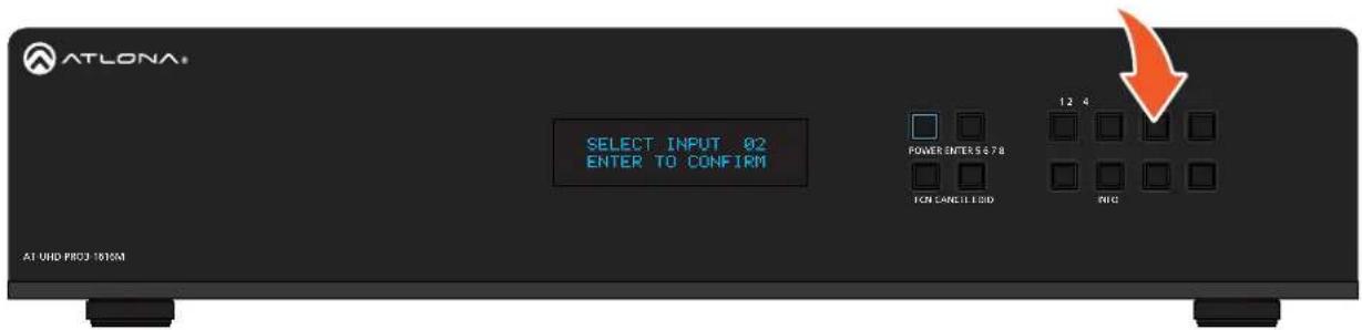
- Press the ENTER button to confirm the selected input. If a different input is desired, press the CANCEL button to return to the home screen, then press the button of the desired input.
SELECT INPUT 03
ENTER TO CONFIRM
- Press the button for the desired output. If a different output is desired, press the CANCEL button to return to the home screen, then press the button of the desired output. In this example, HDBaseT OUT 4 will be selected by pressing button 4.
SELECT OUTPUT 04
ENTER TO CONFIRM
- Press the ENTER button to complete the routing process. The front panel display will confirm the current routing selection.
INPUT 03 ROUTED TO
OUTPUT 04
Using the web GUI
As in the previous example, HDMI IN 3 will be routed to ZONE OUT 4.
- Login to the web GUI. Refer to Introduction to the Web GUI (page 54) for more information.
- Click I/O, under the Configuration section, in the menu bar on the left side of the screen.
- In the row labeled Out 4: Output_4, click the drop-down list to the far right, and select In 3: Input_3.

- Click the Save button to commit changes. HDMI IN 3 is now routed to ZONE OUT 4.
Routing a Single Input to All Outputs
Using the Front Panel
This procedure will route a single input to all eight outputs.
- Make sure the home screen is displayed. If the home screen is not displayed, press the CANCEL button to return to the home screen.
- Press and release the FNC button to display the Select Function screen.

- Press button 1 to execute the Route To All Outputs function.
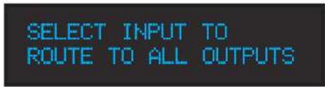
- Press the button for the desired input. In this example, HDMI IN 2 is selected by pressing button 2. The front panel display will confirm the current routing selection.
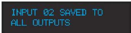
Using the web GUI
As in the previous example, HDMI IN 2 will be routed to all outputs.
- Login to the web GUI. Refer to Introduction to the Web GUI (page 54) for more information.
- Click I/O, under the Configuration section, in the menu bar on the left side of the screen.
- Under the Input/Output Selection section, click the Output "All" drop-down list and select the input to be routed. In this example, HDMI IN 2 will be selected.

- Click the Save button to commit changes. HDMI IN 2 is now routed to all outputs.
Output Mirroring
In addition to the HDBaseT outputs, the AT-UHD-PRO3-1616M also provides four HDMI output ports (highlighted in the image below).

These four HDMI ports are used to mirror (copy) an HDBaseT output signal and duplicate it on any or all of these ports. By default, mirroring is enabled on these ports. However, mirroring can be disabled. When mirroring is disabled, any of the 16 HDMI inputs can be routed to these HDMI outputs, transforming this product into an 16 x 20 matrix switcher. The default mirror settings are listed below
| HDMI Port | Signal that is mirrored (default) |
| HDMI OUT 17 | HDBaseT OUT 13 |
| HDMI OUT 18 | HDBaseT OUT 14 |
| HDMI OUT 19 | HDBaseT OUT 15 |
| HDMI OUT 20 | HDBaseT OUT 16 |
Changing the Mirrored Port
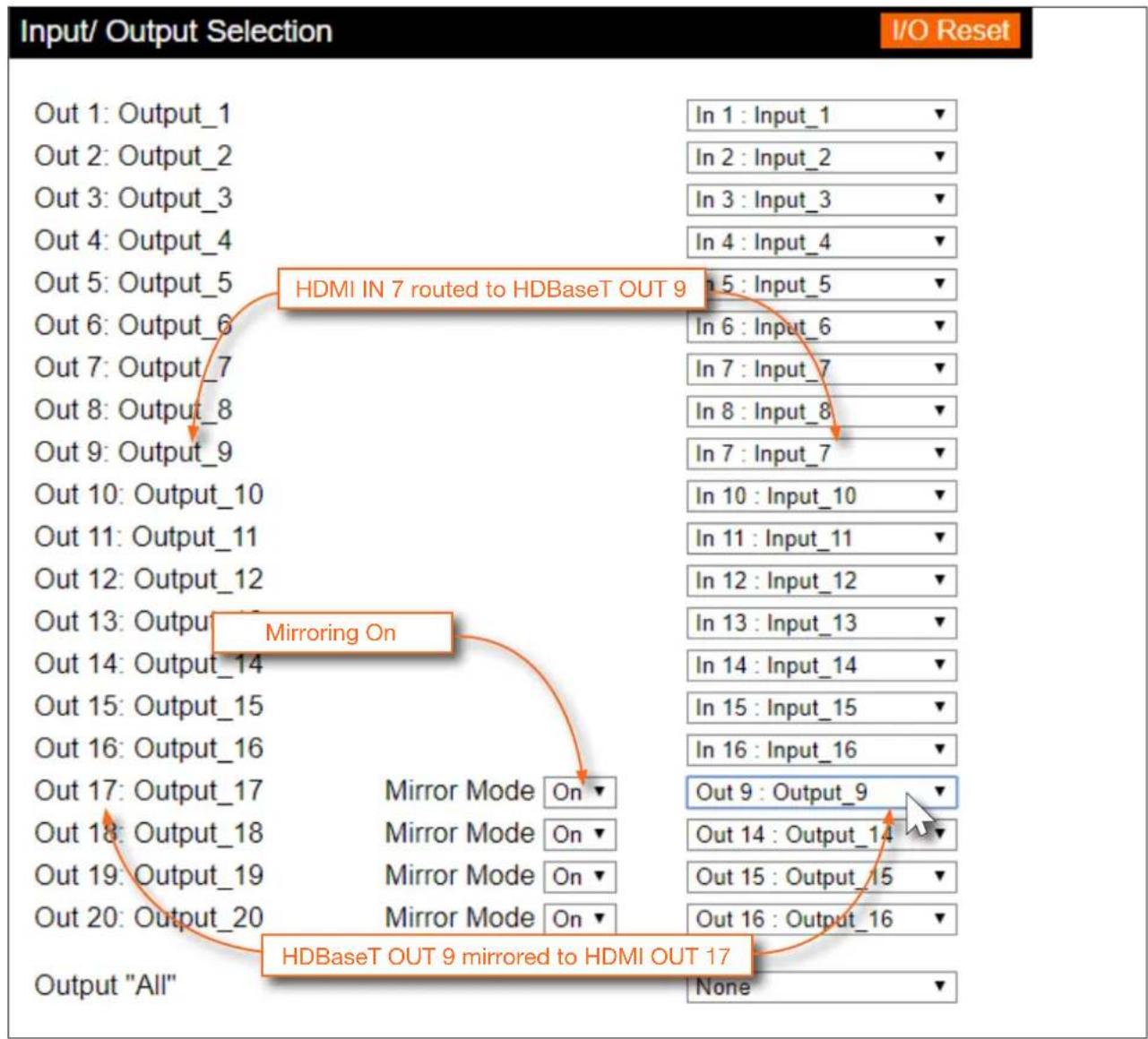
Mirroring is enabled, by default. The diagram below, illustrates the signal flow of mirroring HDBaseT OUT 9 to HDMI OUT 17. The instructions on the following page provide the steps to reproduce this configuration. Two sources have been connected to the matrix: one to HDMI IN 7 and the other to HDMI IN 2. HDMI IN 7 will be used in this example.

flowchart
graph TD
    A["Source 1"] -->|HDMI IN.7| B["AT-UHD-PRO3-1616M"]
    C["Source 2"] -->|HDMI IN.2| B
    B -->|HDMI OUT.17| D["Display"]
    B -->|HDMI OUT.19| E["AT-UHD-EX-100CE-RX"]
    E -->|HDS8| F["Display"]
    B -->|HDS8+OUT.19| G["Display"]
    style B fill:#000,stroke:#fff,color:#fff
    note right of B: A/V Signal

NOTE: Name descriptors in the web GUI are different than those of the port names on the enclosure (e.g. Out 9: Output_9 = HDBaseT OUT 9), and are used interchangably in this document. Therefore, it is recommended to refer to ports by the their number, until they are changed. Refer to Input and Output Management (page 34) for more information on this topic.
- Login to the web GUI. Refer to Introduction to the Web GUI (page 54) for more information.
- Click I/O, under the Configuration section, in the menu bar on the left side of the screen.
- Click the drop-down list, across from Out 9: Output_9, and select In 7: Input_7. This step routes the source that is connected to HDMI IN 7 to HDBaseT OUT 9.
- Click the Mirror Mode drop-down list for Out 17: Output_17, and select On (if not already selected). On is the default setting.
- Click the drop-down list, across from Out 17: Output_17, and select Out 9: Output_9. This instructs the matrix to mirror the source signal on HDBaseT OUT 9 to HDMI OUT 17.
- Click the Save button to commit changes.
flowchart
graph TD
    A["Out 1: Output_1"] --> B["In 1: Input_1 ▼"]
    C["Out 2: Output_2"] --> D["In 2: Input_2 ▼"]
    E["Out 3: Output_3"] --> F["In 3: Input_3 ▼"]
    G["Out 4: Output_4"] --> H["In 4: Input_4 ▼"]
    I["Out 5: Output_5"] --> J["In 5: Input_5 ▼"]
    K["Out 6: Output_6"] --> L["In 6: Input_6 ▼"]
    M["Out 7: Output_7"] --> N["In 7: Input_7 ▼"]
    O["Out 8: Output_8"] --> P["In 8: Input_8 ▼"]
    Q["Out 9: Output_9"] --> R["In 7: Input_7 ▼"]
    S["Out 10: Output_10"] --> T["In 10: Input_10 ▼"]
    U["Out 11: Output_11"] --> V["In 11: Input_11 ▼"]
    W["Out 12: Output_12"] --> X["In 12: Input_12 ▼"]
    Y["Out 13: Output_13"] --> Z["In 13: Input_13 ▼"]
    AA["Out 14: Output_14"] --> AB["In 14: Input_14 ▼"]
    AC["Out 15: Output_15"] --> AD["In 15: Input_15 ▼"]
    AE["Out 16: Output_16"] --> AF["In 16: Input_16 ▼"]
    AG["Out 17: Output_17"] --> AH["Mirror Mode On ▼"]
    AI["Out 18: Output_18"] --> AJ["Mirror Mode On ▼"]
    AK["Out 19: Output_19"] --> AL["Mirror Mode On ▼"]
    AM["Out 20: Output_20"] --> AN["Mirror Mode On ▼"]
    AO["HDMI IN 7 routed to HDBaseT OUT 9"] --> AP["In 5: Input_5 ▼"]
    AQ["Mirroring On"] --> AR["In 10: Input_10 ▼"]
    AS["HDBaseT OUT 9 mirrored to HDMI OUT 17"] --> AT["Output "All" None ▼"]
Disabling Mirroring
When mirroring is disabled, an input can then be routed to that HDMI output. The diagram below now shows HDMI IN 2 routed to HDMI OUT 17. Note that the output on HDBaseT OUT 9 is from the source connected to HDMI IN 7, which was used when mirroring was enabled.
The instructions on the next page provide the necessary steps to routing HDMI IN 2 to the HDMI OUT 17 output.
Diagram showing HDMI IN 2 routed to HDMI OUT 17 (mirroring diabled)

flowchart
graph TD
    A["Source 1"] -->|HDMI IN.7| B["AT-UHD-PRO3-1616M"]
    C["Source 2"] -->|HDMI IN.2| B
    B -->|HDBaseT OUT.9| D["AT-UHD-EX-100CE-RX"]
    D -->|HDMI| E["Display"]
    B -->|HDMI OUT.17| F["Display"]
    F -->|A/V Signal| G["Output"]
Basic Operation
- Login to the web GUI. Refer to Introduction to the Web GUI (page 54) for more information.
- Click I/O, under the Configuration section, in the menu bar on the left side of the screen.
- Click the Mirror Mode drop-down list, to the right of Out 17: Output_17, and select Off.
- Click the drop-down list, to the right of Out 17: Output_17, and select In 2: Input_2. This instructs the matrix to route HDMI IN 2 to HDMI OUT 17.
- Click the Save button to commit changes.

flowchart
graph TD
    A["Output "All""] --> B["Mirror Mode Off"]
    B --> C["Output_1: Output_1"]
    B --> D["Output_2: Output_2"]
    B --> E["Output_3: Output_3"]
    B --> F["Output_4: Output_4"]
    B --> G["Output_5: Output_5"]
    B --> H["Output_6: Output_6"]
    B --> I["Output_7: Output_7"]
    B --> J["Output_8: Output_8"]
    B --> K["Output_9: Output_9"]
    B --> L["Output_10: Output_10"]
    B --> M["Output_11: Output_11"]
    B --> N["Output_12: Output_12"]
    B --> O["Output_13: Output_13"]
    B --> P["Output_14: Output_14"]
    B --> Q["Output_15: Output_15"]
    B --> R["Output_16: Output_16"]
    B --> S["Output_17: Output_17"]
    B --> T["Output_18: Output_18"]
    B --> U["Output_19: Output_19"]
    B --> V["Output_20: Output_20"]
    B --> W["Output "All""]

    X["In 1: Input_1"] --> Y["✓"]
    Z["In 2: Input_2"] --> AA["✓"]
    AB["In 3: Input_3"] --> AC["✓"]
    AD["In 4: Input_4"] --> AE["✓"]
    AF["In 5: Input_5"] --> AG["✓"]
    AH["In 6: Input_6"] --> AI["✓"]
    AJ["In 7: Input_7"] --> AK["✓"]
    AL["In 8: Input_8"] --> AM["✓"]
    AN["In 7: Input_7"] --> AO["✓"]
    AP["In 10: Input_10"] --> AQ["✓"]
    AR["In 11: Input_11"] --> AS["✓"]
    AT["In 12: Input_12"] --> AU["✓"]
    AV["In 13: Input_13"] --> AW["✓"]
    AX["In 14: Input_14"] --> AY["✓"]
    AZ["In 15: Input_15"] --> BA["✓"]
    BB["In 16: Input_16"] --> BC["✓"]
    BD["In 2: Input_2"] --> BE["✓"]
    BF["Out 14: Output_14"] --> BG["✓"]
    BH["Out 15: Output_15"] --> BI["✓"]
    BJ["Out 16: Output_16"] --> BK["✓"]

    style A fill:#f9f,stroke:#333
    style B fill:#ccf,stroke:#333
    style C fill:#cfc,stroke:#333
    style AD fill:#fcc,stroke:#333
    style AE fill:#cff,stroke:#333
    style AF fill:#ffc,stroke:#333
    style AG fill:#cfc,stroke:#333
    style AH fill:#fcc,stroke:#333
    style AI fill:#cfc,stroke:#333
    style AJ fill:#fcc,stroke:#333
    style AK fill:#cfc,stroke:#333
    style AL fill:#fcc,stroke:#333
    style AM fill:#cfc,stroke:#333
    style AN fill:#fcc,stroke:#333
    style AO fill:#cfc,stroke:#333
    style AP fill:#fcc,stroke:#333
    style AQ fill:#cfc,stroke:#333
    style AR fill:#fcc,stroke:#333
    style AS fill:#cfc,stroke:#333
    style AT fill:#fcc,stroke:#333
    style AU fill:#fcc,stroke:#333
    style AV fill:#fcc,stroke:#333
    style AW fill:#fcc,stroke:#333
    style AX fill:#fcc,stroke:#333
Creating and Editing Routing Presets
Using presets provides a quick and efficient way of switching between multiple routing configurations. The AT-UHD-PRO3-1616M provides 50 memory locations that can be used to store each preset. The following section covers creating, editing, and using routing presents.
Creating a Routing Preset
- Login to the web GUI. Refer to Introduction to the Web GUI (page 54) for more information.
- Click Route Memory, under the Configuration section, in the menu bar on the left side of the screen.
- Create the desired routing state(s). Video and audio routing is similar to the I/O screen. Refer to Routing Inputs to Outputs (page 22).
- Click the drop-down list, next to each output, to set the desired routing state. In this example below, Preset_2 will be used to store the current routing state. The Mirror Mode drop-down lists can also be changed as desired, and will be stored as part of the routing preset.

- Click the Save button to commit changes.
Recalling a Preset
- Login to the web GUI. Refer to Introduction to the Web GUI (page 54) for more information.
- Click Route Memory, under the Configuration section, in the menu bar on the left side of the screen.
- Click the drop-down list under Memory Selection and select the desired preset. In this example, M2: Preset_2 is being selected.

- Click the Select button to invoke the selected routing state.
Editing Presets
- Login to the web GUI. Refer to Introduction to the Web GUI (page 54) for more information.
- Click Route Memory, under the Configuration section, in the menu bar on the left side of the screen.
- Select the desired preset from the Preset Select drop-down list.

- Click the drop-down list, next to each output, to set the new routing state. For more information on how to modify routing states, refer to Routing Inputs to Outputs (page 22) and Audio Routing (page 31).
- Click the Save button to commit changes.
Renaming Presets
By default, each of the 50 memory locations used for routing presets are M1 : Preset_1, M2 : Preset_2, and so on. When dealing with multiple presets, it is helpful to use more descriptive names for easy identification.
- Login to the web GUI. Refer to Introduction to the Web GUI (page 54) for more information.
- Click Route Memory, under the Configuration section, in the menu bar on the left side of the screen.
- Select the desired preset from the Memory label drop-down list.
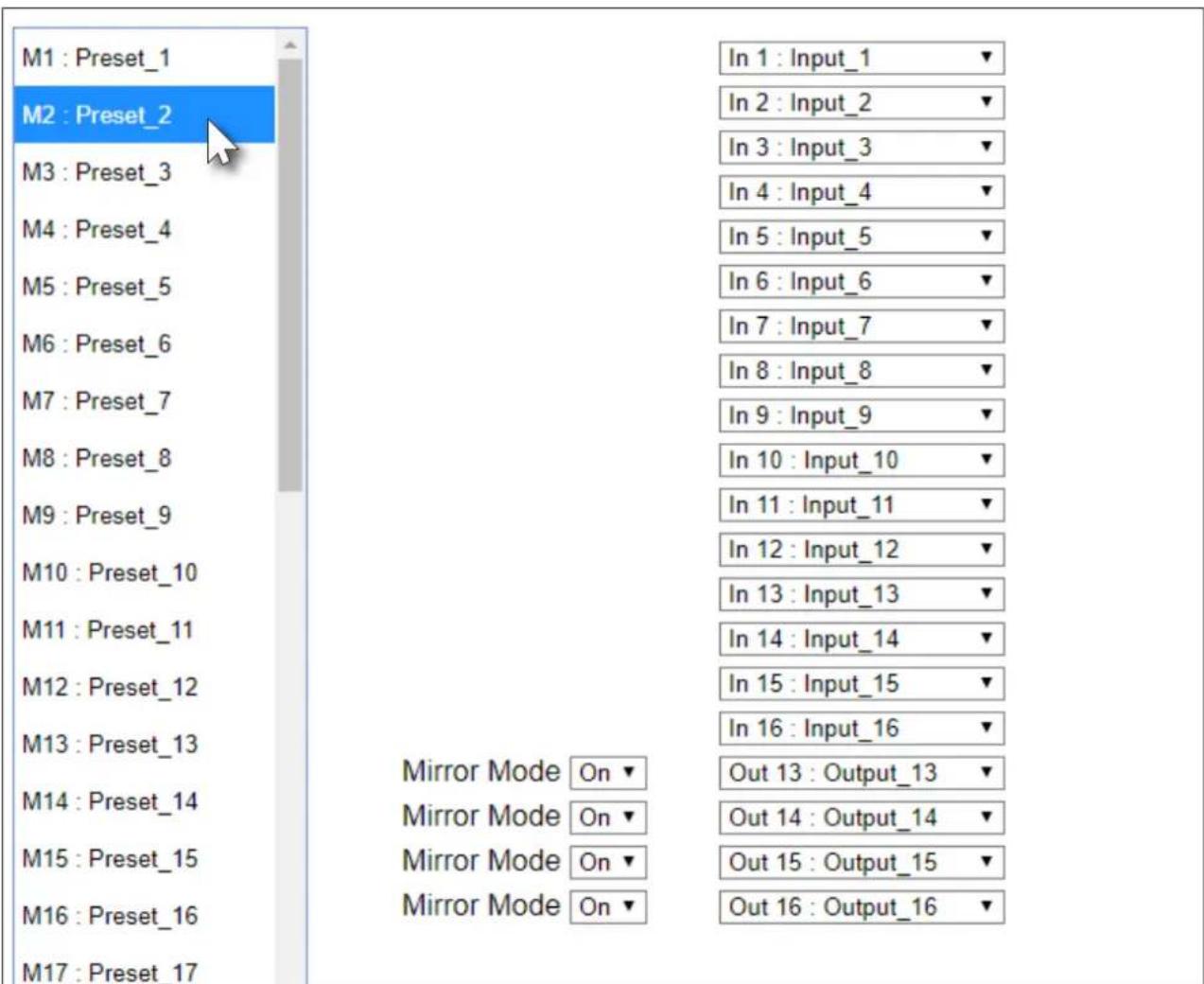
- Enter the name of the preset in the Memory label text field, as shown in the example below.
- Click the change button to commit the change. All instances for the new input name will now be displayed, throughout the web GUI, as shown:

Input and Output Management
When dealing with multiple sources and multiple output devices, within the web GUI, it can be useful to assign descriptive names to each input and output.
Renaming Inputs
- Login to the web GUI. Refer to Introduction to the Web GUI (page 54) for more information.
- Click I/O, under the Configuration section, in the menu bar on the left side of the screen.
- Click the Input Label drop-down list and select the input to be renamed.
| In 2 : Input_2 | In 10 : Input_10 | |
| In 3 : Input_3 | In 11 : Input_11 | |
| In 4 : Input_4 | In 12 : Input_12 | |
| In 5 : Input_5 | In 13 : Input_13 | |
| In 6 : Input_6 | In 14 : Input_14 | |
| In 7 : Input_7 | In 15 : Input_15 | |
| In 8 : Input_8 | Mirror Mode On ▼ | In 16 : Input_16 ▼ |
| In 9 : Input_9 | Mirror Mode On ▼ | Out 13 : Output_13 ▼ |
| In 10 : Input_10 | Mirror Mode On ▼ | Out 14 : Output_14 ▼ |
| In 11 : Input_11 | Mirror Mode On ▼ | Out 15 : Output_15 ▼ |
| Out 16 : Output_16 ▼ | ||
| None ▼ |
- Enter the desired name of the input in the Input Label field. When entering the name of the input, spaces and special characters are not permitted. In this example, In 3: Input_3 is being renamed as Blu-ray_Player.
- Click the Change button to save the change.

All instances for the new input name will now be displayed, throughout the web GUI, as shown:

Renaming Outputs
- Login to the web GUI. Refer to Introduction to the Web GUI (page 54) for more information.
- Click I/O, under the Configuration section, in the menu bar on the left side of the screen.
- Click the Output Label drop-down list and select the output to be renamed.

- Enter the desired name of the input in the Output Label field. When entering the name of the output, spaces and special characters are not permitted. In this example, Out 2: Output_2 is being renamed as 4KUHD_Display.
- Click the Change button to save the change.

The new name will now be displayed when an output is selected, as shown. Note that if an output is selectable (Output_17 through Output_20 drop-down lists), then it will also appear in the drop-down list.

Renaming Memory Presets
The AT-UHD-PRO3-1616M provides 50 presets for storing routing presets. Each preset can also be renamed with more descriptive names, for easy identification and recall at any time.
- Login to the web GUI. Refer to Introduction to the Web GUI (page 54) for more information.
- Click Route Memory, under the Configuration section, in the menu bar on the left side of the screen.
- Click the Memory label drop-down list and select the memory location to be renamed.

- Enter the desired name of the input in the Memory label field. When entering the name of the preset, spaces and special characters are not permitted. In this example, M3: Preset_3 is being renamed as Meeting_room3.
- Click the Change button to save the change.

The new name will now be displayed when the preset is selected from the drop-down list.

EDID is an acronym for Extended Display Identification Data. Before a source can send a picture and/or audio to a display (or other sink device), the source requests information from the display on what video and audio formats it can support. Once the source has this information, it will send the supported picture and audio resolution that is supported by the display. By default, the AT-UHD-PRO3-1616M loads a “default” EDID on all inputs. This particular EDID provides the source with the highest common resolution and audio information that is supported by all connected displays.
For example, if the matrix is connected to a single 1080p display and two 4K/UHD displays, the 1080p resolution will be used, allowing all three displays to display a picture. However, there may be instances where a specific EDID is desired. The AT-UHD-PRO3-1616M allows EDID data to be stored, loaded, and copied.
Loading EDID Presets
Using the Front Panel
The AT-UHD-PRO3-1616M provides 14 pre-programmed internal EDID selections. These EDID presets can be loaded to any one of the eight inputs (HDMI or HDBaseT). Custom EDID data can also be copied to any input. Refer to Copying a Downstream EDID (page 40) for more information.
- Make sure the home screen is displayed. If the home screen is not displayed, press the CANCEL button to return to the home screen.
- Press the FNC button to display the SELECT FUNCTION screen.

-
Press the EDID button to display the EDID screen.
-
COPY OUTPUT EDID
-
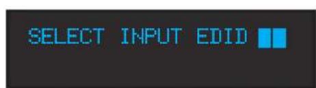
CHOOSE INPUT EDID
-
Press button 2 to select Choose Input EDID.
-
Enter the input to where the EDID will be copied. Valid entries are 1 through 16.
Once the input is entered, the matrix will confirm the entry. If another input is desired, enter it using the front panel buttons. Information on the current EDID will also be displayed on this screen.

Basic Operation
- Press the ENTER button to confirm the entry.
- Press button 3 to select the INT (internal) option.
INPUT:01 MODE: 1: DFLT 2: SAVED 3: INT
- Select the desired EDID by pressing button 1 or 2. Press button 1 to move forward through the list of EDID selections. Press button 2 to move backward through the list. Refer to the table below for a list of available EDID selections.
INT EDID 01 + ENTER ATL 1080P 2CH
The following table lists the available EDID selections.
| EDID Front Panel Display EDID Front Panel Display | |||
| EDID 01 ATL 1080P 2CH EDID 09 ATL 1280x800 RGB CH | |||
| EDID 02 ATL 1080P Multi CH EDID 10 ATL 1366x768 RGB CH | |||
| EDID 03 ATL 1080P DD EDID 11 ATL 1080P DVI | |||
| EDID 04 ATL 1080P 3D 2CH EDID 12 ATL 1280x800 RGB DVI | |||
| EDID 05 ATL 1080P 3D MultiCH EDID 13 ATL 4K30 2CH | |||
| EDID 06 ATL 1080P 3D DD EDID 14 ATL 4K30 MultiCH | |||
| EDID 07 ATL 720P 2CH EDID 15 ATL 4K60 2CH | |||
| EDID 08 ATL 720P DD EDID 16 ATL 4K60 MultiCH | |||
- Press the ENTER button to copy the selected EDID to the input.
Using the web GUI
- Login to the web GUI. Refer to Introduction to the Web GUI (page 54) for more information.
- Click EDID, under the Configuration section in the menu bar on the left side of the screen.
- Click the EDID Selection drop-down list, next to the desired input, to select the EDID. In this example, the ATL 720P DD EDID is being selected for HDMI IN 3.
Note that if a custom EDID was stored in memory, from a downstream sink device, it will also be displayed in the drop-down list. Refer to Copying a Downstream EDID (page 40) for more information.
| 8: Output_8 | ATL 1080P 3D 2CH | none | |
| 9: Output_9 | ATL 1080P 3D MultiCH | none | |
| 10: Output_10 | ATL 1080P 3D DD | none | |
| 11: Output_11 | ATL 720P 2CH | none | |
| 12: Output_12 | ATL 720P DD | none | |
| 13: Output_13 | none | ||
| 14: Output_14 | ATL 1280x800 RGB 2CH | none | |
| 15: Output_15 | ATL 1366x768 RGB 2CH | none | |
| 16: Output_16 | ATL 1080P DVI | none | |
| 17: Output_17 | ATL 1280x800 RGB DVI | none | |
| 18: Output_18 | none | ||
| 19: Output_19 | ATL 4K30 2CH | none | |
| 20: Output_20 | ATL 4K30 MultiCH | none | |
| ATL 4K60 2CH | |||
| ATL 4K60 MultiCH | |||
- Click the Save button to commit changes. The source device, routed to this input, will now use this EDID instead of the downstream EDID (of the sink device).
Copying a Downstream EDID
In some instances, it may be desirable to use the EDID of a connected display, and store it for later use. The AT-UHD-PRO3-1616M provide ten memory locations that can be used to store custom EDID data. Once the EDID is stored in memory, it can be copied to any input. These memory locations are non-volatile, meaning that even if the matrix is powered-off, the EDID data will be retained in these memory locations.
Using the Front Panel
- Make sure a display/sink device is connected to the output where the EDID will be captured. For example, to capture the EDID on HDMI OUT 1, a display/sink device must be connected to that port.
- Start from the home screen. If the home screen is not displayed, press the CANCEL button to return to the home screen. Press the FNC button to display the SELECT FUNCTION screen.

-
Press the EDID button to display the EDID screen.
-
COPY OUTPUT EDID
-
CHOOSE INPUT EDID
-
Press button 1 to select Copy Output EDID.
-
Enter the output from which the EDID will be copied. Valid entries are 1 through 20.
COPY OUTPUT EDID ENTER TO CONFIRM
Once the output is entered, the matrix will confirm the entry. If copying the EDID fails, then a "failure message" will be displayed.
EDID copied successfully. EDID copy failed.
OUTPUT EDID 01 TO MEMORY PASSED
OUTPUT EDID 01 TO MEMORY FAILED
Using the web GUI
- Verify that a display or other sink device is connected to the output from which the EDID will be read. In this example, a display is connected to HDMI OUT 1.
- Login to the web GUI. Refer to Introduction to the Web GUI (page 54) for more information.
- Click EDID, under the Configuration section in the menu bar on the left side of the screen.
- Click the EDID Memory drop-down list for the output, where the sink is connected, and select the memory location. Each of the 20 outputs have an associated memory location: Output_1 = EDID Memory 1, Output_2 = EDID Memory 2, and so on.
EDID
(Extended display identification data)
EDID Reset
| Output | Output EDID | EDID Memory |
| 1 : Output_1 | none ▼ | |
| 2 : Output_2 | none ▼ | |
| 3 : Output_3 | none ▼ | |
| 4 : Output_4 | none ▼ | |
| 5 : Output_5 | none ▼ | |
| 6 : Output_6 | none ▼ | |
| 7 : Output_7 | none ▼ | |
| 8 : Output_8 | DEL DELL P2415Q | none ▼ |
| 9 : Output_9 | none | |
| 10 : Output_10 | EDID Memory 8none ▼ | |
| 11 : Output_11 | ||
| 12 : Output_12 | none ▼ | |
| 13 : Output_13 | none ▼ | |
| 14 : Output_14 | none ▼ | |
| 15 : Output_15 | none ▼ | |
| 16 : Output_16 | none ▼ | |
| 17 : Output_17 | none ▼ | |
| 18 : Output_18 | none ▼ | |
| 19 : Output_19 | none ▼ | |
| 20 : Output_20 | none ▼ |
Save
Cancel
- Click the Save button to commit changes. If the EDID is recorded successfully, then a message will be displayed indicating that the EDID was saved to the selected memory location.
The stored EDID can now be copied to any of the available inputs, as shown in the illustration, below. Refer to EDID Management (page 37) for more information. When selecting an EDID to be copied to an input, always click the Save button to commit changes.
To clear all stored EDID data from the AT-UHD-PRO3-1616M, click the EDID Reset button, shown in the illustration on the previous page.
| 14: Output_14 | Memory 1 | none | |
| 15: Output_15 | Memory 2 | none | |
| 16: Output_16 | Memory 3 | none | |
| 17: Output_17 | Memory 4 | none | |
| 18: Output_18 | Memory 5 | none | |
| 19: Output_19 | Memory 6 | none | |
| 20: Output_20 | Memory 7 | none | |
| DEL DELL P2415Q | |||
| Input | Memory 9 | ||
| 1: Input_1 | ATL 1080P 2CH | ||
| 2: Input_2 | ATL 1080P 2CH | ||
| 3: Input_3 | ATL 1080P 2CH | ||
| 4: Input_4 | ATL 1080P 2CH | ||
| 5: Input_5 | ATL 1080P 2CH | ||
| 6: Input_6 | ATL 1080P 2CH | ||
| 7: Input_7 | ATL 1080P 2CH | ||
| 8: Input_8 | ATL 1080P 2CH | ||
| 9: Input_9 | ATL 1080P 2CH | ||
| 10: Input_10 | ATL 1080P 2CH | ||
| 11: Input_11 | ATL 1080P 2CH | ||
| 12: Input_12 | ATL 1080P 2CH | ||
| 13: Input_13 | ATL 1080P 2CH | ||
| 14: Input_14 | ATL 1080P 2CH | ||
| 15: Input_15 | ATL 1080P 2CH | ||
| 16: Input_16 | ATL 1080P 2CH | ||
Managing Users
The AT-UHD-PRO3-1616M allows the Admin user to create, edit, and remove additional TCP/IP users. All users have the same level of access to control the AT-UHD-PRO3-1616M. However, only the Admin user is allowed to manage other users. Up to three additional users can be created.

NOTE: Usernames and passwords are restricted to alphanumeric characters, only.
Adding Users
- Open the desired web browser and enter the IP address of the AT-UHD-PRO3-1616M.
- Log in as the Admin user with the required credentials. The factory-default username and password for the admin user are listed below:
Username: root
Password: Atlona
- Click the Users tab.

- Enter the desired username and password for the desired user field: User 1, User 2, or User 3.
Change user name and password
| No. | Username | Password | Action |
| User 1 | minion | abcd1234 | |
| User 2 | |||
| User 3 |
-
Click the Add button, under the Action column, next to the user field.
-
Once created, the new user and the associated password will appear under the All User Login Settings section. To login with the new username, click Logout in the upper-right corner of the screen, then enter the login credentials for the user on the Login page.
Change user name and password
| No. | Username | Password | Action |
| User 1 | minion | abcd1234 | SaveDelete |
| User 2 | Add | ||
| User 3 | Add |
Editing / Deleting Users
The username and password of a user can be changed using this method.
- Open the desired web browser and enter the IP address of the AT-UHD-PRO3-1616M.
- Log in as the Admin user with the required credentials. The factory-default username and password for the admin user are listed below:
Username: root
Password: Atlona
- Click the Users tab.

Editing Users
a. Click in the Username or Password field for the desired user and update the current information.
b. Click the Save button to commit changes.
Change user name and password
| No. | Username | Password | Action |
| User 1 | minion | abcd1234 |  |
| User 2 |  | ||
| User 3 |  |
Deleting Users
a. Click the Delete button next to the user to be deleted. Note that no prompt will be provided to confirm the deletion of the desired user.
Advanced Operation
RS-232 Control
The AT-UHD-PRO3-1616M provides RS-232 control between an automation system and an RS-232 device using a captive screw connector block. The AT-UHD-PRO3-1616M provides two modes of RS-232 control: Pass-through mode and control mode.
RS-232 is serial data protocol that allows Data Terminal Equipment (DTE) devices, such a computer or control system, to communicate with Data Communication Equipment (DCE) devices, such as the AT-UHD-PRO3-1616M, amplifier, or display. Although IP control is available, RS-232 still plays an integral part of many control systems.
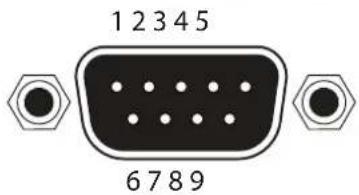
Although the 25-pin D-type connector (DB-25) was defined as the RS-232 standard, it is now commonly implemented in a nine-pin (DE-9) connector package and is numbered, as shown below.
DE-9 (male) DE-9 (female)

DTE Pin Descriptions
| Pin Signal Description | ||
| 1 DCD | Data Carrier | Detect |
| 2 RxD | Receive Data | |
| 3 TxD | Transmit Data | |
| 4 DTR | Data Terminal Ready | |
| 5 GND | Ground (Signal) | |
| 6 DSR | Data Set Ready | |
| 7 RTS | Request to Send | |
| 8 CTS | Clear to Send | |
| 9 RI Ring Indicator | ||
DCE Pin Descriptions
| Pin Signal Description | ||
| 1 DCD | Data Carrier | Detect |
| 2 TxD | Transmit Data | |
| 3 RxD | Receive Data | |
| 4 DSR | Data Set Ready | |
| 5 GND | Ground (Signal) | |
| 6 DTR | Data Terminal Ready | |
| 7 CTS | Clear to Send | |
| 8 RTS | Ready to Send | |
| 9 RI Ring Indicator | ||
Determining the Port Type
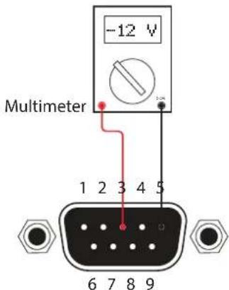
Most DTE devices provide a male connector, while DCE devices have a female connector. However, this is not always the case. If the port type is unknown, then a multimeter can be used to determine whether the port is DTE or DCE:
- Turn on the multimeter and set it to measure DC voltage.
- Connect the positive and negative leads to pins 3 and 5, respectively.
- Check the voltage reading:
If the voltage is between -3 V DC and -15 V DC, then the device is DTE. Otherwise, it is DCE.
Voltage levels between -3 V and -15 V DC represent a logic "1". Voltage levels between +3 V and +15 V DC represent a logic "0".
Cable Assembly
When connecting a DTE device to a DCE device, a straight-through cable should be used. A straight-through cable is wired in such a way that the pins on one side of the cable are connected to the corresponding pins on the opposite side of the cable, as shown in the table below. However, the AT-UHD-PRO3-1616M will use only TxD, RxD, and GND signals when communicating with a control system or computer.
Straight-Through Cable
| Pin Signal Signal Pin | ||||
| 1 DCD DCD 1 | ||||
| 2 RxD TxD 2 | ||||
| 3 TxD RxD 3 | ||||
| 4 DTR DSR 4 | ||||
| 5 GND GND | 5 | |||
| 6 DSR | DTR 6 | |||
| 7 | RTS | CTS | 7 | |
| 8 | CTS | RTS | 8 | |
| 9 RI | RI | 9 | ||
- Identify the DE-9 connector that will be attached to the control system or computer (DCE) equipment.
- Remove the DE-9 connector at the opposite end of the cable with wire cutters.
- Remove at least 1" of the cable insulation to expose each of the nine wires.
- Locate a multimeter and set it to the "continuity" function.
- Attach one of the leads from the multimeter to pin 2 on the DE-9 connector.
- Take the other lead and probe each of the wires on the opposite end of the cable. When the wire connected to that pin is detected, the multimeter will emit an audible tone. Once this occurs, identify the current wire, and move it to the side.
- Repeat step 6 for pin 3 and pin 5 on the DE-9 connector.
- Group the remaining wires and pull them aside. Electrical tape can be use to secure the wires to the outside of the RS-232 cable.
- Remove at least 3/16" (5 mm) of insulation from the TxD, RxD, and GND wires.

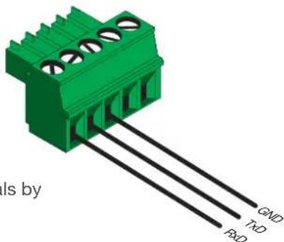
- Locate the included 3-pin captive screw block and open each of the terminals by turning the screws counter-clockwise, using a small regular screwdriver.
- Insert the TxD, RxD, and GND wires into correct terminal, as shown, and tighten the screws to secure each wire. Do no overtighten.
- Connect the captive screw connector to the RS-232 port on the AT-UHD-PRO3-1616M.
Advanced Operation
Pass-through mode
In pass-through mode, RS-232 commands are sent to the AT-UHD-PRO3-1616M and then transmitted over HDBaseT to the receiver unit (e.g. AT-UHD-100CE-RX), and then to the display (sink) device.
- Connect the RS-232 cable between the control system and the AT-UHD-PRO3-1616M. Refer to Cable Assembly (page 47) for instructions on preparing the cable.
- Connect an Ethernet cable from the desired HDBaseT OUT port to a receiver. In this example, the HDBaseT cable is connected from HDBaseT OUT 3 to an AT-UHD-100CE-RX receiver.
- Connect an RS-232 cable between the display (sink) and the receiver.
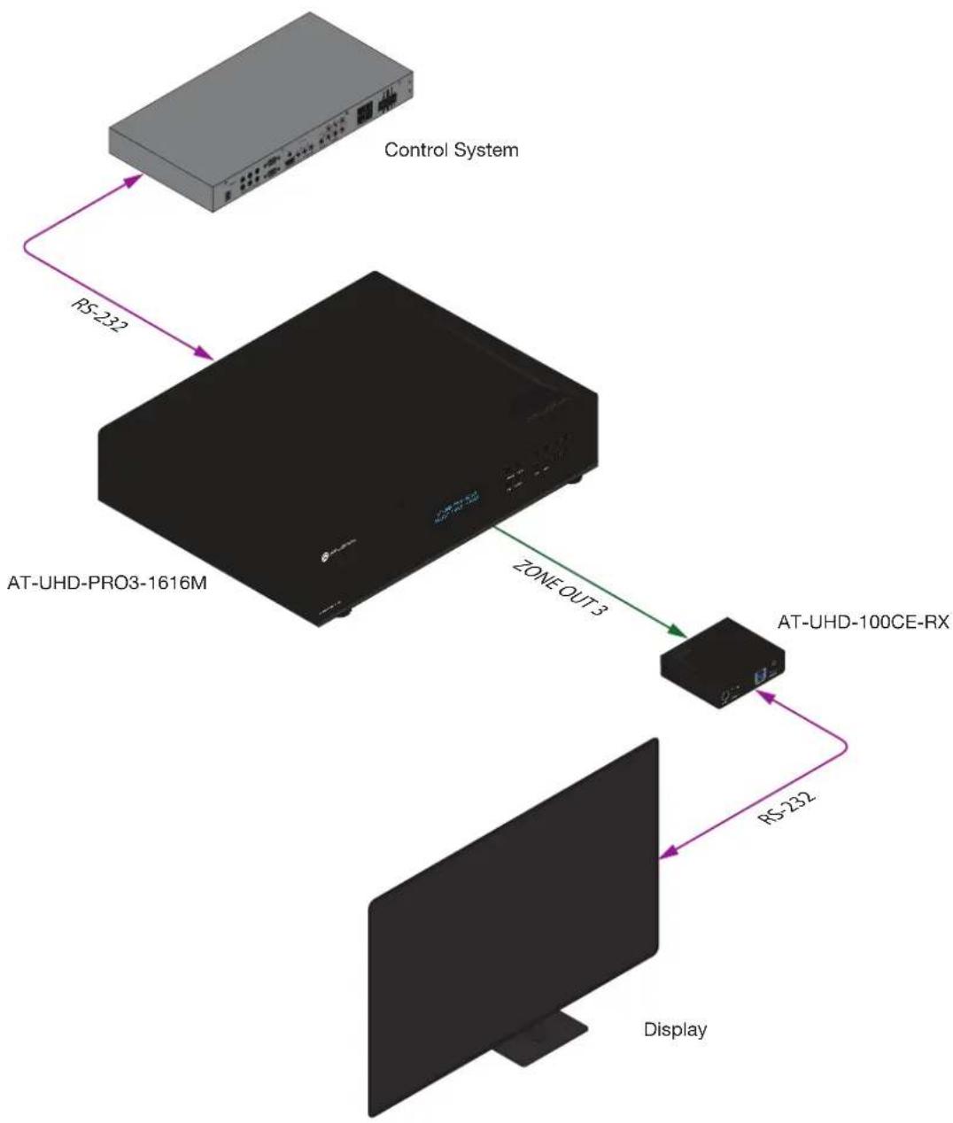
flowchart
graph TD
    A["Control System"] -->|RS-232| B["AT-UHD-PRO3-1616M"]
    B -->|ZONE OUT 3| C["AT-UHD-100CE-RX"]
    C -->|RS-232| D["Display"]
Advanced Operation
- Launch a web browser and login to the web GUI. Refer to Introduction to the Web GUI (page 54) for more information. The factory-default username and password are listed below:
Username: root
Password: Atlona
- Click Control in the side menu bar.
- Select the proper baud rate, data bit, parity, and stop bit settings for the HDBaseT OUT port. These settings must correspond with the RS-232 settings of the receiver unit (e.g. AT-UHD-100CE-RX). Referring to the example diagram on the previous page, ZONE OUT 3 will need to be configured.
Control Settings
Power:
IR:
Key Lock:
Factory Default:
NTP Server:
Time zone:
Blink LED:

OFF

OFF


Reset Now
Server 1
(GMT)
Greenwich Mean Time
Blink
| No. | Baudrate | Parity |
| Matrix | 115200 ▼ | None |
| Output 1: Output_1 | 9600 ▼ | None ▼ |
| Output 2: Output_2 | 9600 ▼ | None ▼ |
| Output 3: Output_3 | 9600 ▼ | None ▼ |
| Output 4: Output_4 | 9600 ▼ | None ▼ |
| Output 5: Output_5 | 9600 ▼ | None ▼ |
- Click the Save button to commit changes.
- Use the following command to send a command to the display (sink) device, where display_command is the command data to send:
RS232Zone4[display_command\$0d]
\$0d (carriage return) should only be added to end of the string if the sink device is expecting this character.
Control mode
In control mode, RS-232 commands are sent from a computer or control system (DTE) to the AT-UHD-PRO3-1616M (DCE). This method allows direct control of the matrix for routing, IP configuration, powering-on / powering-off and other functions.

NOTE: The RS-232 port on the AT-UHD-PRO3-1616M runs at a default baud rate of 115200.
The control unit must be set to the same baud rate, in order to communicate with the AT-UHD-PRO3-1616M.
- Connect the RS-232 cable between the control system and the AT-UHD-PRO3-1616M. Refer to Cable Assembly (page 47) for instructions on preparing the cable.
- Set the baud rate of the computer/control system to 115200. If the control system is not set to this baud rate, then the AT-UHD-PRO3-1616M will not respond to RS-232 commands.
- Refer to the Applications Programming Interface for a listing of available commands.

flowchart
graph TD
    A["Control System"] -->|RS-232| B["AT-UHD-PRO3-1616M"]
IR Control
The AT-UHD-PRO3-1616M feature eight IR IN ports and eight IR OUT ports. Devices at either the headend or connected to the receiver unit can be controlled using IR.
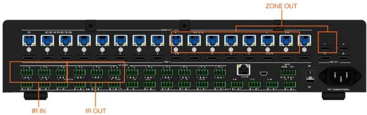
Cable Assembly
The following shows how to control displays (or other sink devices) which are connected to an HDBaseT receiver. Each IR IN port provides IR control for two individual HDBaseT receivers (outputs).
- Remove at least 3/16" (5 mm) of insulation from both the GND and Signal leads.
- Locate the included 4-pin captive screw block and open each of the terminals by turning the screws counterclockwise, using a small regular screwdriver.

- Insert the GND and Signal leads into correct terminal, as shown, and tighten the screws to secure each wire. Do no overtighten.
- Connect the captive screw connector to the IR IN ports on the AT-UHD-PRO3-1616M.

Controlling Display Devices
The following shows how to control displays (or other sink devices) which are connected to an HDBaseT receiver. When a control device is connected to an IR IN port, the IR signal is transmitted over Ethernet cable, from the associated ZONE OUT port, to the HDBaseT receiver. IR IN ports are "hard wired" to each ZONE OUT port.
For example, IR IN 1 is wired to ZONE OUT 1ED, IR IN 2 is wired to ZONE OUT 2ED, and so on. IR IN ports cannot be routed independently.

IMPORTANT: IR IN ports cannot be routed independently. Each IR IN port is associated with a ZONE OUT port: IR IN 1 > ZONE OUT 1ED, IR IN 2 > ZONE OUT 2ED, and so on.
- Connect the IR output of the control system to the IR IN ports on the AT-UHD-PRO3-1616M, using the included 4-pin captive screw connector blocks. Refer to Cable Assembly (page 51) for more information.
- Connect an Ethernet cable from the desired ZONE OUT port on the AT-UHD-PRO3-1616M to an HDBaseT receiver. Note that the IR IN port and the ZONE OUT port numbers must match. For example, in order to send IR commands over the ZONE OUT 4ED port, the IR port of the control system must be connected to IR IN 4 on the AT-UHD-PRO3-1616M. This example is illustrated, below.

flowchart
graph TD
    A["Control System"] -->|IR IN-4| B["AT-UHD-PRO3-1616M"]
    B -->|ZONE OUT 4ED| C["AT-UHD-EX-100CE-RX"]
    C -->|HDMI| D["Display"]
    D -->|IR Emitter| C
    style A fill:#99ccff,stroke:#333
    style B fill:#99ccff,stroke:#333
    style C fill:#99ccff,stroke:#333
    style D fill:#99ccff,stroke:#333
Controlling Headend Devices
Source devices (at the headend) can be controlled from the viewing location. IR control depends upon the current routing state: only the currently viewed source can be controlled using IR.
- Connect the IR receiver (AT-IR-CS-RX) to the HDBaseT receiver, at the viewing location. Although a control system can be used, a basic IR receiver is commonly used.
- Connect an IR emitter to the desired IR OUT port on the AT-UHD-PRO3-1616M. Make sure the source device is within range of the IR emitter.
In the example below, the HDMI IN 4 has been routed to ZONE OUT 6. The IR remote control for the Set Top Box (STB) is connected to the HDBaseT receiver (AT-UHD-EX-100CE-RX) on ZONE OUT 6. As long as the STB is routed to ZONE OUT 6, the STB can be controlled from the viewing location. If a different source is routed to ZONE OUT 6, then the STB can no longer be controlled from the viewing location, using IR.

flowchart
graph TD
    A["Set-Top Box"] -->|HDMI (HDMI IN 4)| B["AT-UHD-PRO3-1616M"]
    B -->|HDBaseT (ZONE OUT 8)| C["AT-UHD-EX-100CE-RX"]
    C -->|HDMI| D["Display"]
    B -->|IR Emitter (IR OUT 2)| B
    B -->|IR Receiver| C
    C -->|IR Remote (Set-Top Box Control)| D
    style A fill:#99ccff,stroke:#333
    style B fill:#99ccff,stroke:#333
    style C fill:#99ccff,stroke:#333
    style D fill:#ccc,stroke:#333

NOTE: In addition to IR control for the headend device, the AT-MRC-IR can also be used from the viewing location to control the AT-UHD-PRO3-1616M.
The Web GUI
Introduction to the Web GUI
The AT-UHD-PRO3-1616M includes a built-in web GUI. Atlona recommends that the web GUI be used to set up the matrix, as it provides intuitive management of all features. Follow the instructions below to access the webGUI.
- Make sure that an Ethernet cable is connected between the LAN port on the AT-UHD-PRO3-1616M and the network.
- Launch a web browser and enter the IP address of the unit. If the default static IP address is being used, enter 192.168.1.254.
If the IP address of the AT-UHD-PRO3-1616M is not known, press and release the FNC button on the front panel, then repeatedly press the INFO button until the IP address is displayed, as illustrated in the example below. Refer to Displaying the System Settings (page 20) for more information, if necessary.

-
Enter root, using lower-case characters, in the User name field.
-
Type Atlona in the Password field. This is the default password. The password field is case-sensitive. When the password is entered, it will be masked.
-
Click the Login button or press the ENTER key on the keyboard.

- The Status page will be displayed.
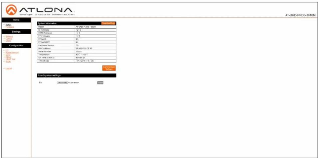
Menu Bar
The window on the left side of the screen is the is the menu bar and lists all available menus. Click on the desired menu item to open that page.

Status page
After logging in, the Status page will be displayed. The Status page provides basic information about the matrix, including the model name, software version, MAC address, and operating temperature.

Model
The model (SKU) of this product.
UI Firmware
The firmware version of the user interface (web GUI).
HDMI Firmware
The firmware version for the HDMI driver. Note that this number is not the version of HDMI.
FP Firmware
Version of firmware used to operate the front panel display.
FPGA Version
The FPGA firmware version.
Hardware Version
The hardware version.
MAC Address
The MAC address of the unit.
Serial Number
The serial number of the unit. The serial number is a 19-digit number that is appended to the model of the matrix, in order to create the hostname identifier.
Temperature
The current operation temperature of the matrix.
On-Time (d:h:m:s)
The time elapsed since the matrix was powered or rebooted.
Time of Day
The current time and date.
Save System Settings
Click this button to save the current system configuration to a local file.
Choose File
Click this button to select the configuration file to be loaded. Click the Load button to upload the file to the system.
Firmware page
This page provides information on the current firmware for the matrix and all connected UHD-EX-based HDBaseT receivers/transmitters. In addition, both matrix and transmitter/receiver (if connected) firmware can be updated here. Refer to Updating the Firmware (page 67) for more information on firmware update procedures.

UI Firmware
The firmware version of the user interface (web GUI).
HDMI Firmware
The firmware version for the HDMI driver. Note that this number is not the version of HDMI.
FP Firmware
Version of firmware used to operate the front panel display.
Out 1 : Output\_1 - Out 10 : Output\_16
Version of firmware used by the HDBaseT receiver (if connected). If no receiver is connected, then No Link will be displayed in these fields.
Choose File (Matrix)
Click this button to select the firmware file for the matrix. Click the Update button to being the firmware update process.
FPGA Version
The FPGA firmware version.
HDBaseT TX VS100
Version of firmware used by the VS100 HDBaseT transmitter chip.
HDBaseT TX VS10
Version of firmware used by the VS10 HDBaseT transmitter chip.
Choose File (HDBaseT Remote)
Click this button to select the firmware file for the HDBaseT remote device (if connected). Click the Update button to being the firmware update process.
Network page

System Secure (SSH)
Secure Socket Shell. Click ON to enable this feature. The default setting is OFF. Enabling this feature will disable the Telnet daemon and web server.
DHCP
Click ON to set the matrix to DHCP mode. If a DHCP server is not found within 15 seconds, then the unit will default to the static IP address of 192.168.0.150. Refer to Setting the IP Mode (page 14) for more information on setting the IP mode. When Mode is set to DHCP, the IP Address, Subnet, and Gateway fields will automatically be populated. Click OFF to set the matrix to static IP mode.
IP Address
Enter the IP address of the AT-UHD-PRO3-1616M in this field. This field will only be available if DHCP is set to OFF. The default IP address is 192.168.0.150.
Subnet
Enter the subnet mask in this field. This field will only be available if DHCP is set to OFF.
Gateway
Enter the gateway (router) address in this field. This field will only be available if DHCP is set to OFF.
Telnet Port
Enter the Telnet listening port in this field.
HTTP Port
Enter the HTTP listening port in this field.
IP Timeout
Enter the timeout interval, in seconds, before the Telnet connection is automatically terminated after no activity. Range: 1 to 3600 (seconds).
Hostname
Enter the hostname of the matrix in this field. This name is used to identify the matrix on a network.
SDDP
Simple Device Discovery Protocol. SDDP is a discovery ("IP scan") protocol authored by Control4® to provide easy integration of the AT-UHD-PRO3-1616M with Control4® devices on a network. SDDP functions similar to the UPnP (Universal Plug and Play) protocol. Click this button to invoke SDDP.
Telnet Login Mode
Click ON to prompt for login credentials at the start of a Telnet session. Use the same credentials as the web GUI. If set to OFF, then no authentication is offered.
Save
Click this button to commit all changes.
Cancel
Click to abort changes.
Control page

Power
Click ON to power-on the matrix. Click OFF to place the matrix in standby mode. Refer to Standby Mode (page 18) for more information on standby mode.
IR
Enables or disables the IR ports on the matrix.
Key Lock
Click ON to lock the button on the front panel. Click OFF to unlock the front-panel buttons. When the front-panel buttons are locked, the POWER button will flash blue.
Factory Default
Click the Reset Now button to set the matrix to factory-default settings.
NTP Server
Click this drop-down list to specify the desired NTP server. Two NTP servers are available: Server 1 or Server 2.
Time Zone
Click this drop-down list to select the desired time zone. The default setting is Greenwich Mean Time (GMT).
Blink LED
Click the Blink button to flash the POWER button on the front panel. When clicked, the Blink button will read Blinking and the POWER button will flash blue.
This process will continue until the Blinking button is clicked.
RS-232
Click these drop-down lists to select the required baud rate and parity bit for the device that is being controlled.
Save
Click this button to commit all changes.
Cancel
Click to abort changes.
Users page
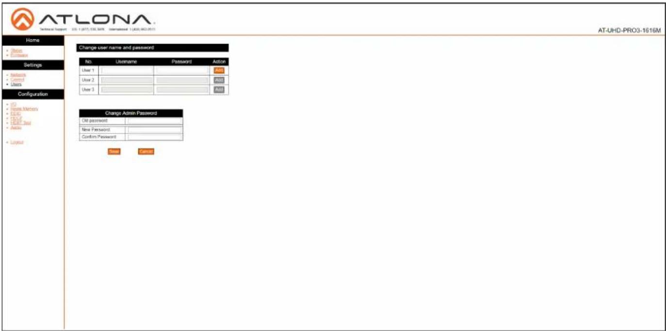
Username
Enter the username in this field. Only alphanumeric characters are accepted in this field.
Password
Enter the password for the user in this field. Only alphanumeric characters are accepted in this field.
Add
Click this button to add a TCP/IP user. The Username and Password fields must be completed before a new user can be added.
Old Password
Enter the current password for the "root" username in this field. The default password is "Atlona".
New Password
Enter the new password for the "root" username in this field.
Confirm New Password
Verify the new password by retyping it in this field.
Save
Click this button to commit all changes.
Cancel
Click to abort changes.
I/O page

I/O Reset
Click this button to reset all input/output routing to factory-default settings.
Out 1: Output\_1 - Out 10: Output\_20
Click the drop-down lists, to the right, to select the desired input for routing. Refer to Routing Inputs to Outputs (page 22) for more information.
Output "All"
Click this drop-down list to select the desired input to be routed to all outputs. Refer to Routing a Single Input to All Outputs (page 24) for more information.
Save
Click this button to commit all changes.
Cancel
Click to abort changes.
Input Label
Click this drop-down list to select the desired input to be labeled. Enter the name of the input in the field to the right of the drop-down list. Click Change to commit the input label name. Refer to Renaming Inputs (page 34) for more information.
Output Label
Click this drop-down list to select the desired output to be labeled. Enter the name of the output in the field to the right of the drop-down list. Click Change to commit the name of the output. Refer to Renaming Outputs (page 35) for more information.
Route Memory page
![AT-LONA Network Support: 105.1 (017): 105.3095 International 1 (018): 062.0571 Home Global • Features Settings • Network • Control • Audio Configuration • In • Break Memory • Input • Break • Break Test • Audio • Layout Route Memory (The call app changes for current OS version) Memory Label Present format: In: Present_1 Out 1: Output_1 In 1: Input_1 Out 2: Output_2 In 2: Input_2 Out 3: Output_3 In 3: Input_3 Out 4: Output_4 In 4: Input_4 Out 5: Output_5 In 5: Input_5 Out 6: Output_6 In 6: Input_6 Out 7: Output_7 In 7: Input_7 Out 8: Output_8 In 8: Input_8 Out 9: Output_9 In 9: Input_9 Out 10: Output_10 In 10: Input_10 Out 11: Output_11 In 11: Input_11 Out 12: Output_12 In 12: Input_12 Out 13: Output_13 In 13: Input_13 Out 14: Output_14 In 14: Input_14 Out 15: Output_15 In 15: Input_15 Out 16: Output_16 In 16: Input_16 Out 17: Output_17 Minor Mode [On] Out 17: Output_17 Minor Mode [On] Out 18: Output_18 Minor Mode [On] Out 19: Output_19 Minor Mode [On] Out 20: Output_20 Minor Mode [On] Save Cancel Memory label In: Present_1 Cancel Memory Selection (The app change the current OS solution) In: Present_1 Single](/content/2026/05/986367/images/f5e51fa033e2b52cce725c2c78cdc5e88bbd2e0c121a5188a32feef156e7041e.jpg)
Memory Reset
Click this button to reset preset memory to factory-default settings. Note that performing this function will erase all memory presets.
Output 1 - Output 20
Click the drop-down lists, to the right of the output name, to select the desired input for routing. Refer to Routing Inputs to Outputs (page 22) for more information. Output 17 and Output 20 are used for mirroring. Click the Mirror Mode drop-down list to enable or disable mirroring on the specified output. If Mirror Mode is enabled, then only outputs will be available. If disabled, then inputs will be available.
Save
Click this button to commit all changes.
Cancel
Click to abort changes.
Memory Label
Click this drop-down list to select the desired memory location to be labeled. Enter the name of the memory location in the field to the right of the drop-down list. Click Change to commit the label to the memory location. Refer to Renaming Memory Presets (page 36) for more information.
Memory Selection
Click this drop-down list to select the desired memory preset. Click Select to recall the memory preset. Refer to Creating and Editing Routing Presets (page 30) for more information.
EDID page

EDID Reset
Click this button to reset all EDID settings to the factory-default settings. Note that this will erase any stored EDID data in memory.
Output 1 - Output 20
Click the EDID Memory drop-down list to select the memory location where the EDID, displayed under the Output EDID column, will be stored. Note that each drop-down lists is available, only if a sink device is connected to the output.
Save
Click this button to commit all changes for outputs.
Cancel
Click to abort changes.
Input 1 - Input 16
Click the EDID Selection drop-down lists to assign the desired EDID to an input. Stored EDID data will also be displayed in these drop-down list if EDID data was captured. Refer to EDID Management (page 37) for more information.
Save
Click this button to commit all changes for inputs.
Cancel
Click to abort changes.
HDCP page

Output 1 - Output 20
Displays the connection status of each output.
HDBT Test page

HDBT Zone
Click this drop-down list to select the output channel (ZONE OUT) to test. Refer to HDBaseT Testing (page 70) for more information.
Audio page

Audio Reset
Click this button to reset all audio settings to factory-defaults.
Output
Each output can be assigned different equalizer settings. Click the drop-down list to select the desired output. Once the output is selected, adjust each equalizer band as needed. Click the Save button to commit changes or click the Cancel button to abort changes.
Mute
Click this button to mute the current audio output.
Volume Sliders
Click and drag the volume sliders to set the audio level for each output. Click the Mute button to mute audio for the specified output. When the audio for an output is muted, the Mute button will read Unmute. Click the Unmute button to disabling the muting. Click the Save button to commit changes. Click the Cancel button to abort changes. Audio range for output volume is -79 dB to +15 dB. The default value is -10 dB.
Save
Click this button to commit all changes.
Cancel
Click to abort changes.
Appendix
Updating the Firmware
The AT-UHD-PRO3-1616M is updated through the web GUI.
Required items:
- New firmware - Downloaded from atlona.com
• IP address of the AT-UHD-PRO3-1616M
• Computer on the same network as the AT-UHD-PRO3-1616M -
Username and password to access the web GUI
-
Verify that an Ethernet cable is connected between the AT-UHD-PRO3-1616M and the network. The computer used to access the web GUI must be on the same network as the AT-UHD-PRO3-1616M.
- Type the IP address of the AT-UHD-PRO3-1616M into a web browser, as shown in the example below.


- The login screen will be displayed. Login using the username and password. The default login credentials are:
Username: root
Password: Atlona
-
Click Firmware on the left side of the screen.
-
Click the Choose File button, to select the firmware file.

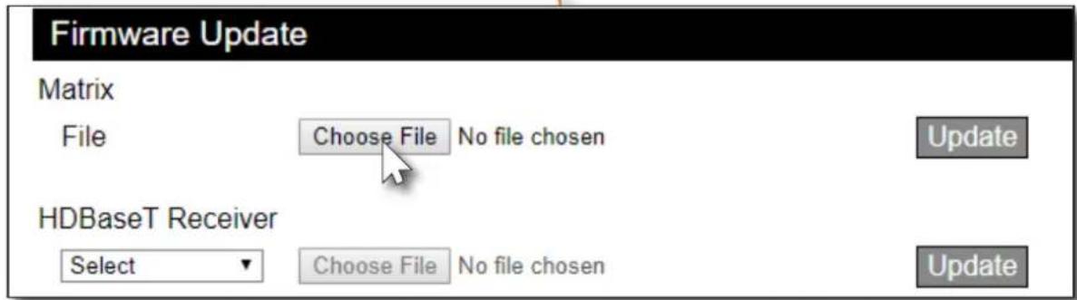
- Click the Update button. A progress bar will be displayed during the update process.
- Once the update has been completed, re-login to the web GUI.
Appendix
Cable Termination
Atlona recommends EIA/TIA-568-B termination. Connector type and size is very important to ensure extenders work correctly. Always use the matching cable type with the correct RJ45 connector.
- CAT5e cables should use only CAT5e RJ45 connectors
- CAT6 cables should use only CAT6 connectors
- CAT6a cables should use only CAT6a connectors
• CAT7 cables should use only CAT7 connectors
Using the wrong size connectors may result in interference causing loss of signal.

WARNING: EZ RJ45 connectors are not recommended with HDBaseT extenders. Doing so may result in interference with audio and video transmission.
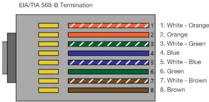
Refer to the tables below for recommended cabling when using Altona products with HDBaseT. The green bars indicate the signal quality when using each type of cable. Higher-quality signals are represented by more bars.
| Core | Cable Type | CAT5e | CAT6 | CAT6a | CAT7 |
| Solid Unshielded Twisted Pair (UTP) N/A N/A | |||||
| Shielded Twisted Pair (STP) | |||||

IMPORTANT: Stranded or patch cables are not recommended due to performance issues.
HDBaseT Testing
The web GUI of the AT-UHD-PRO3-1616M provides a tool for testing the signal integrity of HDBaseT cables. This tool is useful for troubleshooting and identifying defective or damaged Ethernet cables which are connected from the ZONE OUT ports to a receiver.
- Login to the web GUI. Refer to Introduction to the Web GUI (page 54) for more information, if necessary.
- Click HDBT Test, under the Configuration section in the menu bar on the left side of the screen.
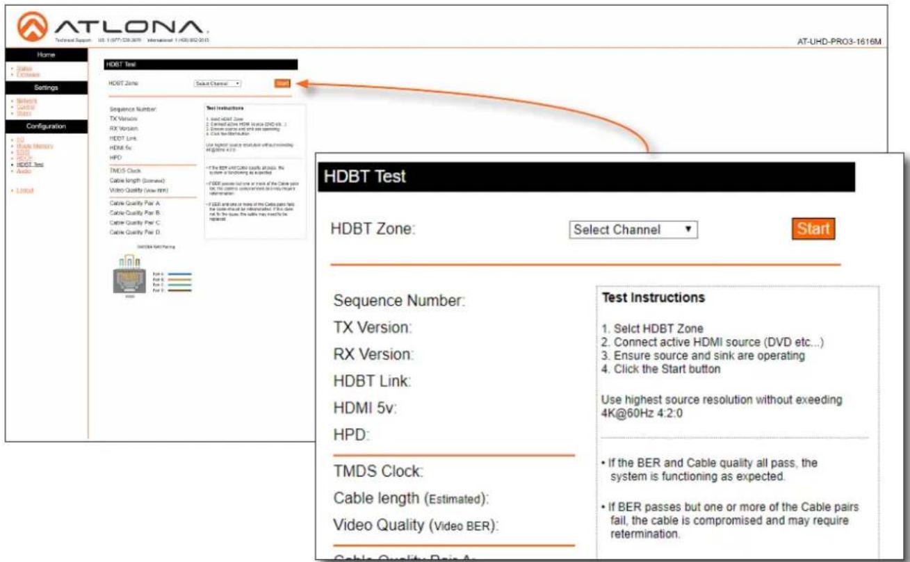
- Click the HDBT Zone drop-down list and select the desired zone to test. Before testing a zone, make sure that an Ethernet cable is connected between the ZONE OUT port and a compatible receiver.

NOTE: The drop-down list provides the option to select any output channel, from Out 1: Output_1 to Out 16: Output_16. However, Out 17: Output_17 through Out 20: Output_20 are HDMI outputs, and are not valid selections. If either of these channels are selected, the Start button will be disabled.
-
Click the Start button to begin testing the selected channel.
-
If the HDBaseT link integrity is good, then all tests will display as "Pass".
- If any part of the HDBaseT cable fails, then a numerical value, in decibels, will be displayed next to the associated pair, under the Signal Quality section. These values can be reported to Atlona Technical Support Engineers to help resolve possible issues.
Default Settings
The following tables list the factory-default settings, as defined in the web GUI, for the AT-UHD-PRO3-1616M.
| Web GUI Page Setting Default Value | ||
| Login Username | Password | rootAtlona |
| Network System Secure (SSH) | OFFON2380300AT-UHD-PRO3-1616M-xxxxxOFF | |
| DHCPTelnet PortHTTP PortIP TimeoutHostnameTelnet Login Mode | ||
| Control Power | ONONOFFServer 1(GMT) Greenwich Mean Time115200None9600 (all HDBaseT zones)None (all HDBaseT zones) | |
| IRKey LockNTP ServerTime zoneBaudrate (Matrix)Parity (Matrix)BaudrateParity | ||
| I/O Out 1: Output_1 | In 1 : Input_1In 2 : Input_2In 3 : Input_3In 4 : Input_4In 5 : Input_5In 6 : Input_6In 7 : Input_7In 8 : Input_8In 9 : Input_9In 10 : Input_10In 11 : Input_11In 12 : Input_12In 13 : Input_13In 14 : Input_14In 14 : Input_15In 14 : Input_16Out 13: Output_13Out 14: Output_14Out 15: Output_15Out 16: Output_16Out 17: Output_17Out 18: Output_18Out 19: Output_19Out 20: Output_20 | |
| EDID 1 : Input_1 | ATL 1080P 2CHATL 1080P 2CHATL 1080P 2CH...ATL 1080P 2CH | |
| Audio Output_1 | -20 dB......-20 dB | |
Mounting Instructions
The AT-UHD-PRO3-1616M can be mounted in a standard 19-inch rack or placed on top of a desk or table.
Rack Installation

IMPORTANT: To prevent possible fire hazards due to overheating, do not block the ventilation holes on either side of the enclosure, which would prevent proper airflow through the unit. In addition, do not exceed the maximum weight capacity for the rack. Install heavier equipment in the bottom portion of the rack for maximum stability.

IMPORTANT: Unit is intended for installation in a restricted access location accessible by authorized personnel only.

IMPORTANT: Unit is intended for installation in a location where children are not present.
- Remove the two screws from either side of the enclosure.
- Attach the included rack ears to each side of the AT-UHD-PRO3-1616M using the enclosure screws.

natural_image
3D rendering of a black AT&T device with control panel and drive slots (no visible text or symbols)- Install the matrix into a rack, as shown using the included rack screws.

natural_image
3D rendering of a black server rack with attached control panel and drive cables (no visible text or symbols)Appendix
Surface Mounting
The AT-UHD-PRO3-1616M can be placed on top of any flat surface. To prevent damage to the surfaces or unnecessary movement of the matrix, four feet have been included.
- Turn the unit upside down.
- Install each foot using the included feet screws, the rubber grips of the feet should be facing up during installation.
- Turn the unit right-side up and place it in the desired location.

natural_image
3D rendering of a black rectangular electronic device with multiple Ethernet ports and indicator lights (no text or symbols visible)Specifications
| Video | ||
| Signal Type Input - HDMI | ||
| Output - HDBaseT, HDMI | ||
| HDCP HDCP 2.2 | ||
| Pixel Clock | 300MHz | |
| UHD/HD/SD | 4096x2160@ 60^(1) / 50^(1) /30/25/24Hz3840x2160@ 60^(1) / 50^(1) /30/25/24Hz1080p@60/59.9/50/30/29.97/25/24/23.98Hz1080i@30/29.97/25Hz | 720p@60/59.94/50Hz576p@50Hz576i@25Hz480p@60/59.96Hz480i@30Hz |
| VESA | 2560x16002048x15361920x12001680x10501600x12001440x9001400x10501280x1024 | 1280x8001366x7681360x7681152x8641024x768800x600640x480 |
| Color Space | YUV, RGB | |
| Chroma Subsampling | 4:4:4, 4:2:2, 4:2:0 | |
| Color Depth | 8-bit, 10-bit, 12-bit | |
| Audio | |||
| HDMI / HDBaseTPass-Through Formats | PCM 2.0LPCM 5.1LPCM 7.1 | Dolby® DigitalDolby Digital PlusTMDolby TrueHD | DTS® Digital SurroundTM DTS-HD Master AudioTM |
| Bit Depth Up to 24 bits | |||
| Analog Audio | |||
| Format Stereo 2-Channel | |||
| Sample Rate 32 kHz, 44.1 kHz, | 48 kHz, 88.2 kHz, 96 kHz, 176.4 kHz, 192 kHz | ||
| Ethernet | |||
| Port 1 x RJ45 | |||
| Standards and Protocols HTTPS, Telnet, mDNS | |||
| Speeds 10/100 Mbps | |||
| Addressing | DHCP, Static – selectable through rear panel, IP & RS-232 commands, and built-in web server | ||
| RS-232 | ||||
| Port 1 x 5-pin captive screw; TX, RX, GND | ||||
| Use Device control and configuration | ||||
| Baud Rates 2400, 4800, 9600, 19200, 38400, 57600, 115200 | ||||
| Data flow Bidirectional pass-through from control system over HDBaseT | ||||
| IR | ||||
| Port 16 x 4-pin captive screw, 1 x 5-pin captive screw; S, GND | ||||
| Use Local input/output and zone control | ||||
| Frequency Range 30 kHz to 60 kHz | ||||
Appendix
| CEC | |
| Port | HDMI, Type A, 19-pin female |
| Triggering Through IP, RS-232, and built-in web server | |
| Resolution / Distance 4K/UHD - Feet / Meters 1080p - Feet / Meters | |||
| HDMI IN/OUT 15 5 30 10 | |||
| CAT5e/6 (Port 1-8) 230 70 100 330 | |||
| CAT5e/6 (Port 9-16) 115 35 60 197 | |||
| CAT6a/7 (Port 1-8) 100 330 100 330 | |||
| CAT6a/7 (Port 9-16) 70 230 70 230 | |||
| Buttons and Indicators | |
| Buttons:Menu and Number 14 - momentary, tact-type | |
| Indicators:Power 1 - LED, blue | |
| Connectors | |
| HDMI IN | 16 - Type A, 19-pin female |
| HDBaseT OUT | 16 - RJ45, female |
| HDMI OUT | 4 - Type A, 19-pin female |
| FW | 1 - Micro-A USB |
| RS-232 | 1 - 3-pin captive screw (bidirectional) |
| IR IN | 17 - 2-pin captive screw (bidirectional) |
| IR OUT | 16 - 2-pin captive screw (bidirectional) |
| AUDIO OUT | 12 - 4-pin captive screw, balanced / unbalanced 2-channel |
| RS-232 | 1 - 3-pin captive screw (bidirectional) |
| LAN | 1 - RJ45, 100Base-T |
| PWR | 1 - Internal 100-240 VAC 50/60Hz, IEC female connector |
| Temperature Fahrenheit Celsius | ||
| Operating 32 to 104 0 to 40 | ||
| Storage | -4 to 140 | -20 to 60 |
| Humidity (RH) 20% to 60%, non-condensing | ||
| Power | |
| Consumption Idle: 100W | Full load: 150W |
| Supply | AC100 - 240 VAC, 50/60 Hz |
| Dimensions | Inches | Millimeters |
| H x W x D w/feet | 3.90 x 17.31 x 11.88 | 99.02 x 439.74 x 301.63 |
| H x W x D w/rack ears | 3.49 x 19.00 x 11.88 | 88.63 x 482.60 x 301.63 |
| Rack Unit | 2U | |
| Weight | Pounds | Kilograms |
| Device | 13.70 | 6.21 |
| Certification | |
| Device | CE, FCC, RoHS, RCM, TUV |

- Welcome to Atlona!
- Sales, Marketing, and Customer Support
- Main Office
- International Headquarters
- Operating Notes
- Atlona, Inc. ("Atlona") Limited Product Warranty
- Coverage
- OR
- Coverage Periods
- Limited Product Warranty Terms – New Products
- Limited Product Warranty Terms - Refurbished (B-Stock) Products and Discontinued Products
- Remedy
- Exclusions
- Disclaimers
- Limitation on Liability
- Exclusive Remedy
- Other Conditions
- Safety and Certification
- CAUTION
- FCC Compliance
- Copyright, Trademark, and Registration
- Table of Contents
- Appendix
- Introduction
- Features
- Package Contents
- Panel Description
- Front Panel Display
- POWER
- FCN
- ENTER
- CANCEL
- Routing / Function Buttons
- EDID
- INFO
- HDBaseT OUT
- HDMI IN
- HDMI OUT
- AUDIO OUT
- IR IN
- IR OUT
- LAN
- FW
- MAIN (RS-232 / IR IN)
- ON/OFF
- PWR 100-240VAC 50/60Hz
- Installation
- Audio Connectors
- Connection Instructions
- OPTIONAL
- Setting the IP Mode
- Using the Front Panel
- Using the web GUI
- Network Settings
- IP Reset
- Basic Operation
- Powering the Matrix
- Standby Mode
- Viewing Matrix Settings
- Viewing the current routing state
- Displaying the System Settings
- Resetting to Factory Defaults
- Routing Inputs to Outputs
- Single Input-to-Output Routing
- Routing a Single Input to All Outputs
- Output Mirroring
- Changing the Mirrored Port
- Disabling Mirroring
- Creating and Editing Routing Presets
- Creating a Routing Preset
- Recalling a Preset
- Editing Presets
- Renaming Presets
- Input and Output Management
- Renaming Inputs
- Renaming Outputs
- Renaming Memory Presets
- Loading EDID Presets
- Copying a Downstream EDID
- Managing Users
- Adding Users
- Change user name and password
- Editing / Deleting Users
- Editing Users
- Deleting Users
- Advanced Operation
- RS-232 Control
- Determining the Port Type
- Cable Assembly
- Pass-through mode
- Control Settings
- Control mode
- IR Control
- Controlling Display Devices
- Controlling Headend Devices
- The Web GUI
- Introduction to the Web GUI
- Menu Bar
- Status page
- Model
- UI Firmware
- HDMI Firmware
- FP Firmware
- FPGA Version
- Hardware Version
- MAC Address
- Serial Number
- Temperature
- On-Time (d:h:m:s)
- Time of Day
- Save System Settings
- Choose File
- Firmware page
- Out 1 : Output\_1 - Out 10 : Output\_16
- Choose File (Matrix)
- HDBaseT TX VS100
- HDBaseT TX VS10
- Choose File (HDBaseT Remote)
- Network page
- System Secure (SSH)
- DHCP
- IP Address
- Subnet
- Gateway
- Telnet Port
- HTTP Port
- IP Timeout
- Hostname
- SDDP
- Telnet Login Mode
- Save
- Cancel
- Control page
- Power
- IR
- Key Lock
- Factory Default
- NTP Server
- Time Zone
- Blink LED
- RS-232
- Users page
- Username
- Password
- Add
- Old Password
- New Password
- Confirm New Password
- I/O page
- I/O Reset
- Out 1: Output\_1 - Out 10: Output\_20
- Output "All"
- Input Label
- Output Label
- Route Memory page
- Memory Reset
- Output 1 - Output 20
- Memory Label
- Memory Selection
- EDID page
- EDID Reset
- Input 1 - Input 16
- HDCP page
- HDBT Test page
- HDBT Zone
- Audio page
- Audio Reset
- Output
- Mute
- Volume Sliders
- Updating the Firmware
- Cable Termination
- HDBaseT Testing
- Default Settings
- Mounting Instructions
- Rack Installation
- Surface Mounting
Brand : Atlona
Model : AT-UHD-PRO3-1616M
Category : Video switch