AT-RGB2416-A - Video switch Atlona - Free user manual and instructions
Find the device manual for free AT-RGB2416-A Atlona in PDF.

User questions about AT-RGB2416-A Atlona
0 question about this device. Answer the ones you know or ask your own.
Ask a new question about this device
Download the instructions for your Video switch in PDF format for free! Find your manual AT-RGB2416-A - Atlona and take your electronic device back in hand. On this page are published all the documents necessary for the use of your device. AT-RGB2416-A by Atlona.
USER MANUAL AT-RGB2416-A Atlona
- Safety Operation Guide 2
1.1 Notice 2 - Introduction 3
2.1 Installation 4 - Operation and Control 17
- Audio Signal Connection 18
- Connecting RGB48/642, RGB48/6432, RGB48/6448, RGB6464 ..... 19
5.1 Front Panel/ Control 19
5.2 Remote Control Operation 23
5.3 Operation of Application Software 23
5.4 Keyboard Tab 25
5.5 Auto Tab 25
5.6 Custom Code Tab 26
5.7 Code Group Tab 27
5.8 Send / Recieve Code List Tab 28 - RS-232 Operation 28
- Technical Specifications 30
- Troubleshooting 32
- Safety Information 33
- Warranty 34
- Atlona Product Registration 35
In order to ensure the credibility and the user's safety, please comply with the following items during installation, maintenance and operation of the switch.
- The switch must be in stable position. Use only the power supply that comes with unit. Do not use an alternate as it may damage it.
- Do not place the switcher near hot or cold surfaces or sources.
- To avoid any damage by over heating, please keep the environment in good ventilation to radiate the heat when running the switcher.
- The switcher should be turned off when it is not used.
- Please do not attempt to take cover off the switcher for there is a high-voltage component inside that could cause electric shock.
- Do not splash any liquid or chemical on or near the equipment.
- Please make sure all the wiring are in working condition and are not cut or damaged.
NOTICE
This RGB Switchers User Manual can be used for other RGB matrix switcher models. This manual is only an instruction for operators, not for any maintenance usage.
Any changes of functions and parameters since then will be informed separately. This manual is copyright Atlona Technologies. All rights reserved. No part of this publication may be copied or reproduced without the prior written consent of Atlona Technologies.
Please check the Atlona website for updates. http://www.atlona.com
INTRODUCTION
The RGBHV series switcher is a high-performance professional switcher built for cross switching between multiple RGBHV or Component Video and Audio Signals. This series of matrix switchers were originally intended to be used for the switching of RGBHV signals, however with Component Video being a more popular and prevalent format, these switchers can be converted using the supplied BNC to RCA adapters. If audio needs to be matrixed separate from the video, we recommend using the models that are designated with “-A” in the product name. All switchers can be controlled by front panel controls, RS232 or IR.
| Specifications/Models | Video Inputs | Video Outputs | Audio Inputs | Audio Outputs | RS232 Interface |
| RGB1616-A | 16 | 16 | 16 | 16 | √ |
| RGB2408 | 24 | 8 | × | × | √ |
| RGB2408-A | 24 | 8 | 24 | 8 | √ |
| RGB2416 | 24 | 16 | × | × | √ |
| RGB2416-A | 24 | 16 | 24 | 16 | √ |
| RGB2424 | 24 | 24 | × | × | √ |
| RGB2424-A | 24 | 24 | 24 | 24 | √ |
| RGB3208 | 32 | 8 | × | × | √ |
| RGB3208-A | 32 | 8 | 32 | 8 | √ |
| RGB3216 | 32 | 16 | × | × | √ |
| RGB3216-A | 32 | 16 | 32 | 16 | √ |
| RGB3224 | 32 | 24 | × | × | √ |
| RGB3224-A | 32 | 32 | 32 | 24 | √ |
| RGB3232 | 32 | 32 | × | × | √ |
| RGB3232-A | 32 | 32 | 32 | 32 | √ |
All modules above are for combined case design.
| RGB4824 | 48 | 24 | × | × | √ |
| RGB4832 | 48 | 32 | × | × | √ |
| RGB4848 | 48 | 48 | × | × | √ |
| RGB6424 | 64 | 24 | × | × | √ |
| RGB6432 | 64 | 32 | × | × | √ |
| RGB6448 | 64 | 48 | × | × | √ |
| RGB6464 | 64 | 64 | × | × | √ |
| RGB9664 | 96 | 64 | × | × | √ |
| RGB9696 | 96 | 96 | × | × | √ |
| RGB12864 | 128 | 64 | × | × | √ |
| RGB12896 | 128 | 96 | × | × | √ |
| RGB128128 | 128 | 128 | × | × | √ |
All modules above are for separated case design; audio case is the optional accessory. There will be wider bandwidth.
INSTALLATION
The RGB Switchers can be easily rack mounted using the rack mount ears located in the front of the unit. Secure the Switch with standard rack-hole screws. It is recommended to leave a 1U space between the units to have easy access for installation of the cables. When connecting the cables make sure all cables are connected correctly; if not, it could cause color loss or will not output a display signal.
Packaging Includes:
• RGB / Component Video Matrix Switcher
• RJ45 & RS-232 Communication Cables
• BNC to RCA adapters
• Power Supply Cord
• CD with Application SWITCHER 2.0
• User Manual and Quality Guarantee
- Remote Control
Front View and Rear View of the Product
Front View of the RGB0802-A、RGB0804-A、RGB0808-A

text_image
Technical diagram of an electronic device rear panel with labeled ports and connector pinsFront View of the RGB1604-A、RGB1608-A

text_image
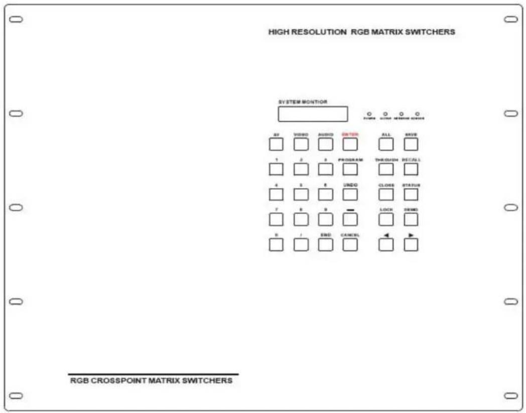
HIGH RESOLUTION RGB MATRIX SWITCHERS SYSTEM MONITOR AV VIDEO AUDIO OUTER ALL SAVE 1 2 3 PROGRAM THROUGH RECALL 4 5 6 UNID CLOSE STATUS 7 8 9 — LOCK DEMO 8 END CANCEL RGB CROSSPOINT MATRIX SWITCHERSRear View of the RGB1604-A、RGB1608-A
text_image
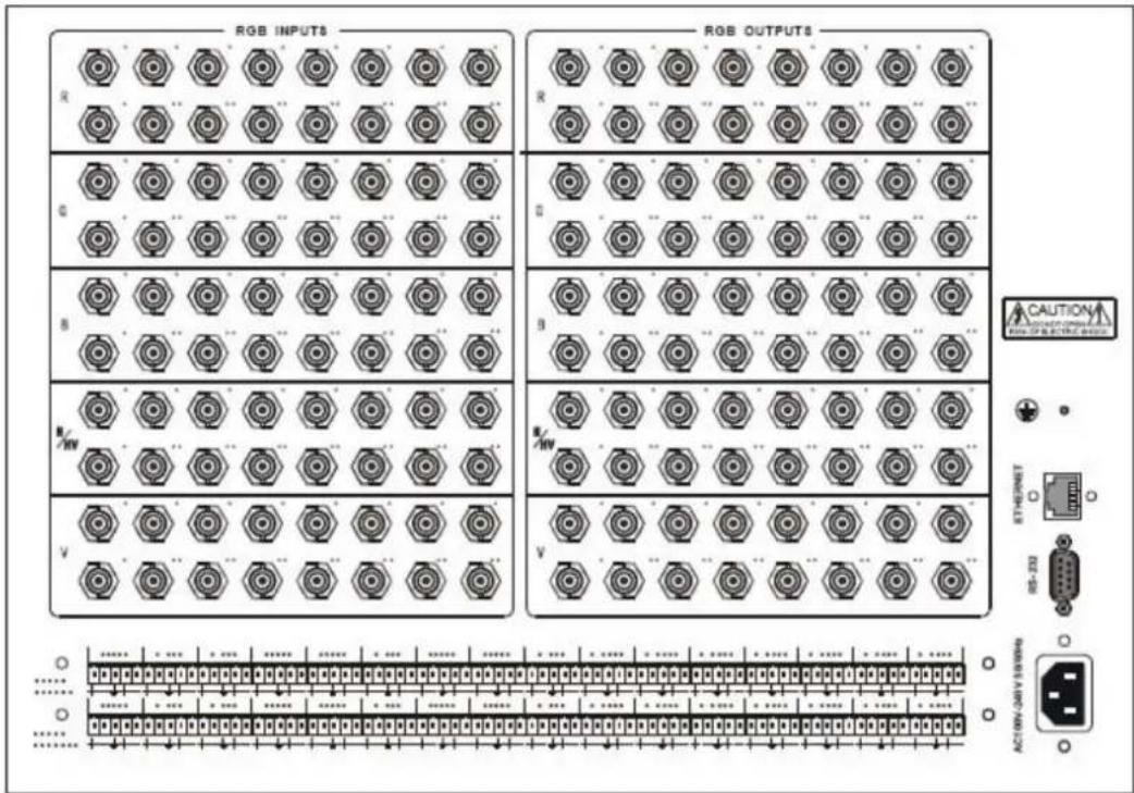
RGB INPUTS RGB OUTPUTS CAUTION R G B N V R G B N V R R R R R R R R R R R R R R R R R R R R R R R R R R R R R R R R R R R R R R R R R R R R R R R R R R A:10V-240V 15/10HzFront View of the RGB1616-A
text_image
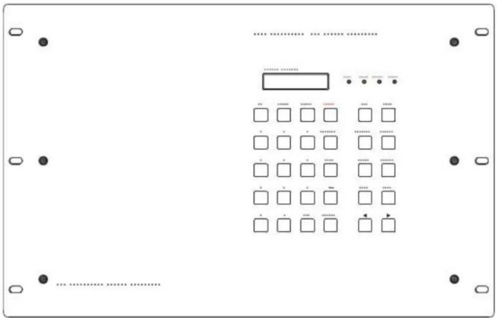
Diagram of a device control panel with labeled buttons and a grid of square indicators for status or operation.Rear View of the RGB1616-A
text_image
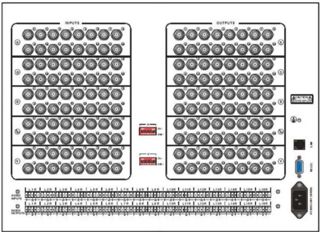
INPUTS OUTPUTS L1R L2R L3R L4R L5R L6R L7R L8R L9R L10R L11R L12R L13R L14R L15R L16R AUDIO INPUTS AUDIO OUTPUTS AC NEAM-LAT SWITCHFront View of the RGB24/3208-A RGB24/3216-A
text_image
HIGH RESOLUTION RGB MATRIX SWITCHERS SYSTEM MONITOR AV VIDEO AUDIO SWITCH ALL SAVE 1 2 3 PROGRAM THRESH RECALL 4 5 6 UNDO CLOSER STATUS 7 8 9 LOCK SWIND 8 / END CANCEL RGB CROSSPOINT MATRIX SWITCHERSRear View of the RGB24/3208-A、RGB24/3216-A

text_image
R G B H V MODE CAUTION EXTRUST RS-22 AUDIO INPUTS L1 R L2 R L3 R • •••• L6 R L6 R L7 R L8 R L9 R L10 R L11 R L12 R L13 R L14 R L15 R L16 R L17 R L18 R L19 R • ••••• L21 R L22 R L23 R L24 R L25 R L26 R L27 R L28 R L29 R L30 R L31 R L32 R L1 R L2 R L3 R • •••• L6 R L6 R L7 R L8 R L9 R L10 R L11 R L12 R L13 R L14 R L15 R L16 R AUDIO OUTPUTSFront View of the RGB24/3224-A RGB3232-A
text_image
508 RESOLUTION RGB MATRIX SWITCHERS L27 M27 SYSTEM MOUNTOR 691 691 691 691 691 691 691 691 691 691 691 691 691 691 691 691 691 691 691 691 691 691 691 691 691 694 694 694 694 694 694 694 694 694 694 694 694 694 694 694 694 694 694 694 694 694 694 694 694 694 695 695 695 695 695 695 695 695 695 695 695 695 695 695 695 695 695 695 695 695 695 695 695 695 695 696 696 696 696 696 696 696 696 696 696 696 696 696 696 696 696 696 697 697 697 697 697 697 697 697 697 697 697 697 697 697 697 697 697 697 697 697 697 697 697 697 697 698Rear View of the RGB24/3224-A、RGB3232-A

text_image
Technical diagram of a device panel with multiple circular components and a corresponding schematic below showing component layout and pin connections.Front View of RGB48/6424、RGB48/6432、RGB48/6448、RGB6464
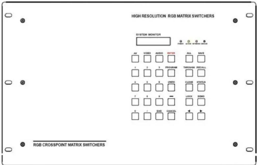
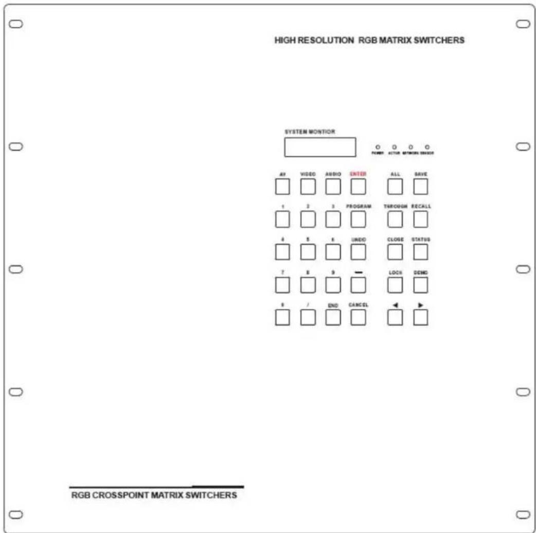
text_image
HIGH RESOLUTION RGB MATRIX SWITCHERS SYSTEM MONITOR FINES ACTIO SWITCHER DESIGN AV VIDEO AUDIO ENTER ALL SAVE 1 2 3 PROGRAM THROUGH RECALL 4 5 6 UNDO CLOSE STATUS 7 8 9 — LOCK SEND 0 / END CANCELRear View of RGB48/6424、RGB48/6432、RGB48/6448、RGB6464(RCH)
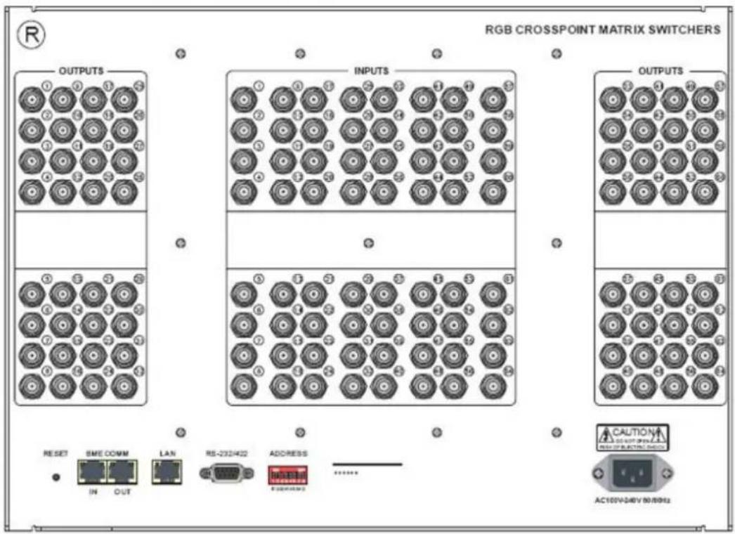
text_image
RGB CROSSPOINT MATRIX SWITCHERS OUTPUTS INPUTS OUTPUTS RESET SME COMM LAN RS-232402 ADDRESS CAUTION AC100V-240V 50/8962Front View of RGB08/1624-A、RGB08/1632-A

text_image
HIGH RESOLUTION RGB MATRIX SWITCHERS SYSTEM MONITOR POWER 100 100 100 AV VIDEO AUDIO SWITCH ALL SAVE 1 2 3 PROGRAM THROUGH RIOCALL 4 5 6 UNDO CLOSE STATUS ? 8 9 — LOCK OEMO + - + BHD CANCELRear View of RGB08/1624-A、RGB08/1632-A

text_image
Technical diagram of a multi-panel electronic device with hexagonal component layouts and control panel layoutRear View of the RGB48/64 Series Audio box
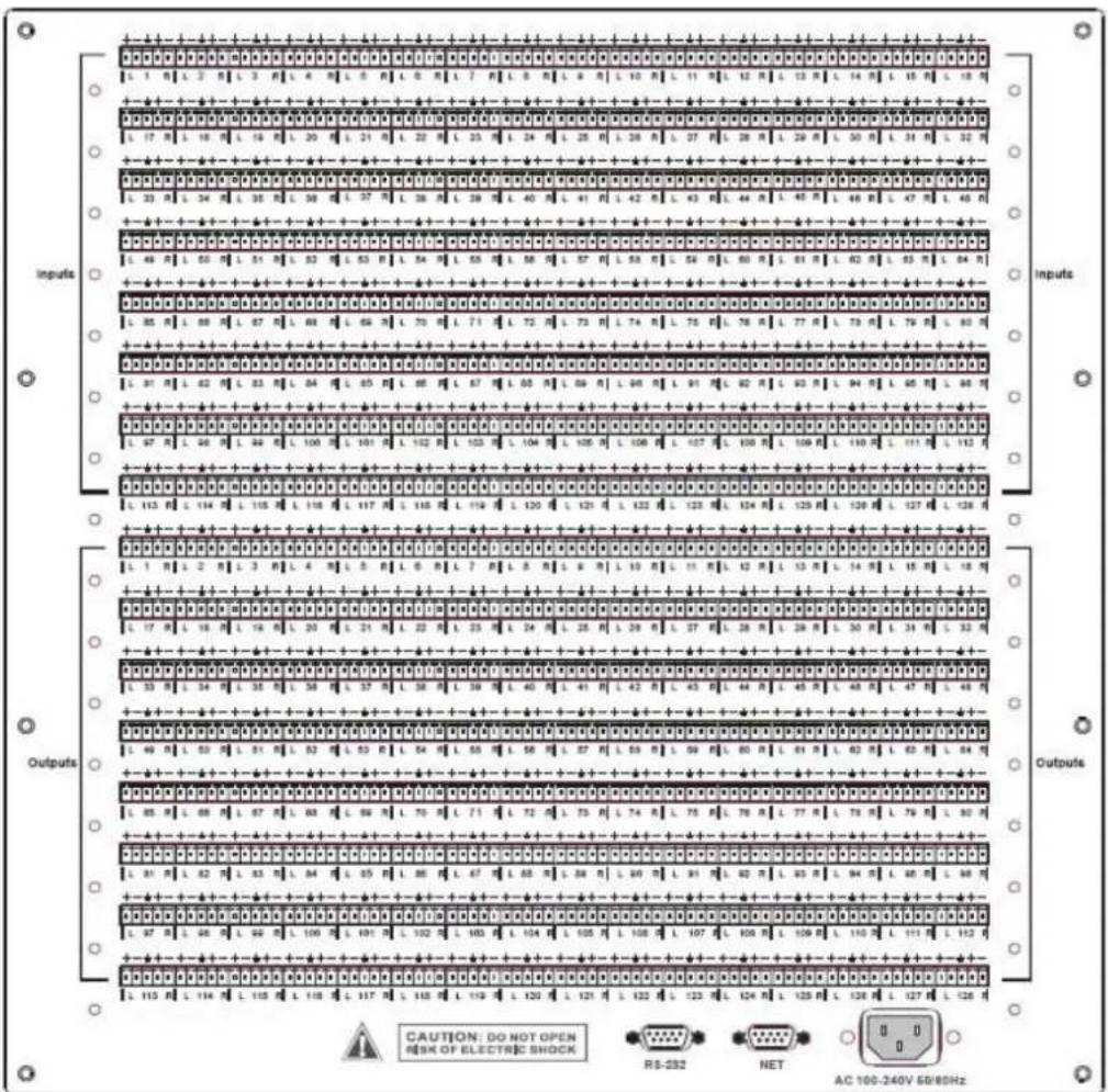
text_image
Inputs Outputs CAUTION: DO NOT OPEN RISK OF ELECTRIC SHOCK RS-232 NET AC 100-240V 68/85Hz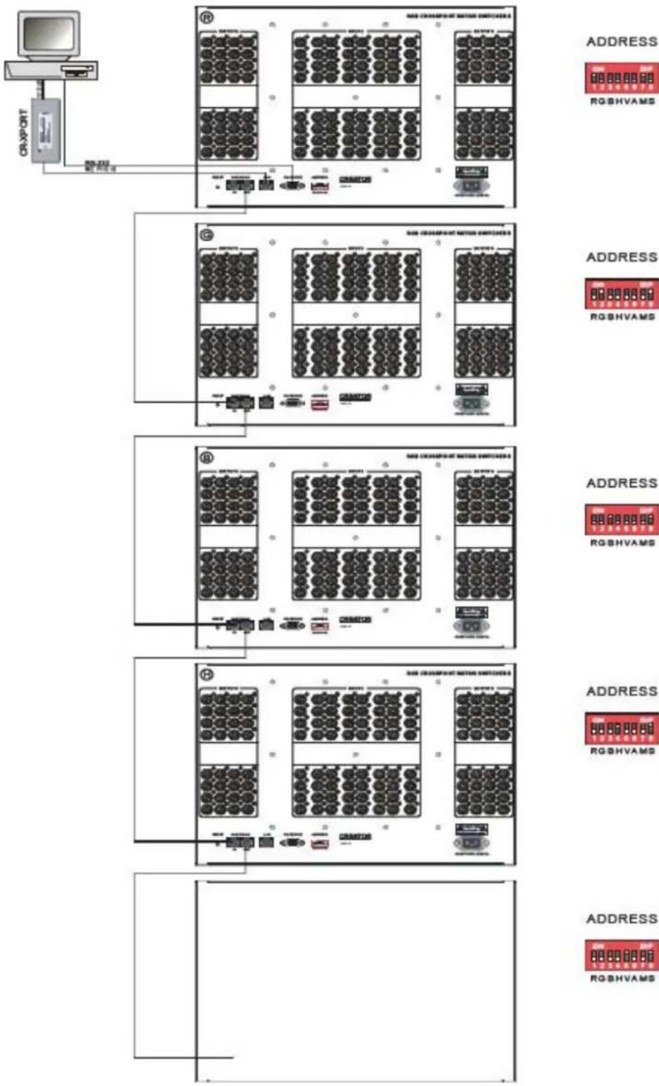
flowchart
graph TD
    A["CRAPORT"] --> B["Switch 1"]
    B --> C["Switch 2"]
    C --> D["Switch 3"]
    D --> E["Switch 4"]
    E --> F["Switch 5"]
    F --> G["Switch 6"]
    G --> H["Switch 7"]
    H --> I["Switch 8"]
    I --> J["Switch 9"]
    J --> K["Switch 10"]
    K --> L["Switch 11"]
    L --> M["Switch 12"]
    M --> N["Switch 13"]
    N --> O["Switch 14"]
    O --> P["Switch 15"]
    P --> Q["Switch 16"]
    Q --> R["Switch 17"]
    R --> S["Switch 18"]
    S --> T["Switch 19"]
    T --> U["Switch 20"]
    U --> V["Switch 21"]
    V --> W["Switch 22"]
    W --> X["Switch 23"]
    X --> Y["Switch 24"]
    Y --> Z["Switch 25"]
    Z --> AA["Switch 26"]
    AA --> AB["Switch 27"]
    AB --> AC["Switch 28"]
    AC --> AD["Switch 29"]
    AD --> AE["Switch 30"]
    AE --> AF["Switch 31"]
    AF --> AG["Switch 32"]
    AG --> AH["Switch 33"]
    AH --> AI["Switch 34"]
    AI --> AJ["Switch 35"]
    AJ --> AK["Switch 36"]
    AK --> AL["Switch 37"]
    AL --> AM["Switch 38"]
    AM --> AN["Switch 39"]
    AN --> AO["Switch 40"]
    AO --> AP["Switch 41"]
    AP --> AQ["Switch 42"]
    AQ --> AR["Switch 43"]
    AR --> AS["Switch 44"]
    AS --> AT["Switch 45"]
    AT --> AU["Switch 46"]
    AU --> AV["Switch 47"]
    AV --> AW["Switch 48"]
    AW --> AX["Switch 49"]
    AX --> AY["Switch 50"]
flowchart
graph TD
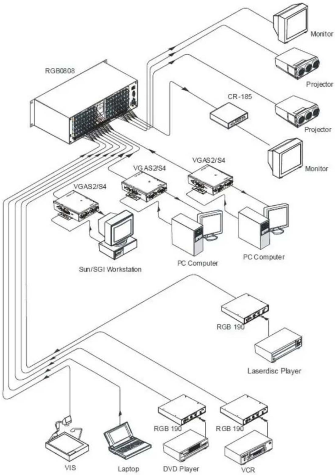
A["RGB0808"] --> B["VRAS2/S4"]
B --> C["PC Computer"]
C --> D["VRAS2/S4"]
D --> E["Monitor"]
D --> F["Projector"]
D --> G["Monitor"]
B --> H["VRAS2/S4"]
H --> I["PC Computer"]
I --> J["VRAS2/S4"]
J --> K["Monitor"]
H --> L["Sun/SGI Workstation"]
L --> M["VRAS2/S4"]
M --> N["PC Computer"]
N --> O["VRAS2/S4"]
O --> P["Monitor"]
H --> Q["Laserdisc Player"]
Q --> R["RGB 190"]
R --> S["PC Computer"]
S --> T["VRAS2/S4"]
T --> U["Monitor"]
H --> V["VIS"]
V --> W["Laptop"]
W --> X["RGB 190"]
X --> Y["PC Computer"]
Y --> Z["VRAS2/S4"]
Z --> AA["Monitor"]
Z --> AB["Projector"]
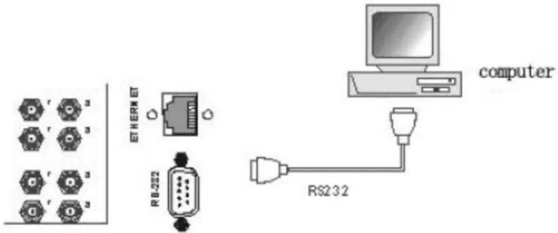
The Switchers can be controlled by front controls or PC, third party automation and control systems, SWITCHER 2.0 control system software or through the Ethernet control via the RS-232 communication port. The RS232 is a female 9-pin D connector. It can be switched by several control systems. When the switcher connects to the COM1 or COM2 of the computer with control software, users can control it by that computer. To control the switcher, users may use the application SWITCHER 2.0 in the supplied CD or develop their own control software.
text_image
r r r r r ETHERM RB-202 computer RS232Connection between RGB matrix switcher and the computer
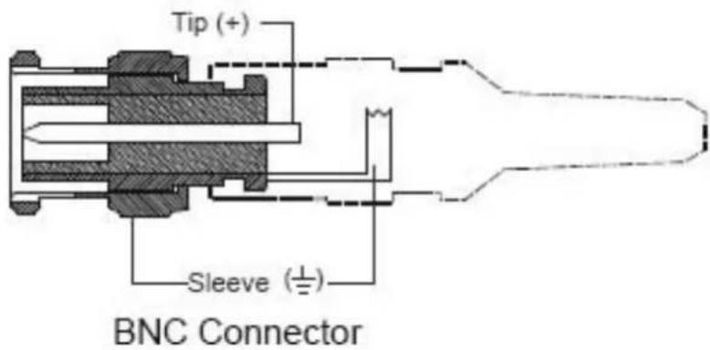
The RGB / Component matrix switchers may take DVD players, computers and graphic workstations as their input signal source, and projectors, video recorders, displays and amplifiers as their output signal depending on different applications. RGBHV connection: The RGB matrix switchers supports the AV video and VGA signal sources. RGBHV signal output terminals or YC output terminals are needed in the AV device; RGBHV signal output terminals are needed in the VGA device. The BNC connector is shown as the figure below. If switching Component Video and 2-channel analog audio, utilize the existing H/V inputs and outputs with the supplied BNC to RCA adapters for connecting the audio inputs and outputs.
text_image
Tip (+) Sleeve (±) BNC ConnectorPlease use the special five core RGB signal cord to connect the input and output devices and connect the BNC connector R (red) G (green) B (blue) H (horizontal) V (vertical) carefully.
Attention:
Please make sure the RGBHV connectors from the sources and to the destination should be in the same Order, Otherwise it could cause color loss or no output signal at all. Use supplied BNC to RCA for Component.
AUDIO SIGNAL CONNECTION
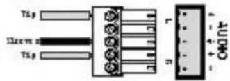
"AUDIO INPUTS", "AUDIO OUTPUTS" audio network interface in RGB matrix switchers can be connected to the audio signal and amplify sources. The audio connection is a little more complicated than video. It has two types of connection: balanced and unbalanced. The balanced connection transmits a pair of balanced signals with two cables. Because interferences will have the same intensity and the opposite phases on the two cables; it will be counteracted in the end. For the low frequency extent of the audio signal, it would be easily interfered under long distance transmission. Therefore as an anti-interference connection, it is mostly used in the connection of special high end devices.
The unbalanced connection transmits signals with only one cable. Without counteraction, it can be interfered more easily. Accordingly, it is adopted for household appliances or some cases with low technical demand. Take the audio signal line for example: 1. Unbalanced: pin "G" connects to SLEEVE, pin "+" connects to TIP, pin "-" connects to pin "G"; 2. Balanced: pin "G" connects to SLEEVE, pin "-" connects to RING, pin "+" connects to TIP.
To select which connection is up to the interface of the device. When available, the balanced connection is the first choice. Before connection, please read the command or relevant demand in the user manual carefully. In some cases, there is balanced in the source signal end but unbalanced in the destination end. If in a nonstandard case, it is done to connect balanced for the balanced end and unbalanced for the unbalanced end. But if in a standard one, the converter must be used to switch the signals as the same, balanced or unbalanced.

Balanced Input

Balanced Output

text_image
Tip Ileve Tip Ileve r n AUDIOUnbalanced Input
Unbalanced Output
CONNECTING RGB48/642,RGB48/6432,RGB48/6448,RGB6464
Step 1, Set box RED as main control box, Set "R" and "M" in the "Address" of R box to the "On" position; Turn the other switches to the "Off" position, All other boxes will need to be set to slave.
Set "G" and "S" of G box to "On" position, others to the "Off" position.
Set "B" and "S" of B box to "On" position, others to the "Off" position.
Set "H" and "S" of H box "On" position, others to the "Off" position.
Set "V" and "S" of V box "On" position, others to the "Off" position.
Step 2, Using a standard CAT5 cable; connect from the OUT port of the back panel BME COMM of the main control box, to the IN port of the back panel to the first sub control box directly. Connect from the OUT port of the backboard BME COMM of the first slave control box, to the IN port of the backboard BME COMM of the second slave control box directly. Repeat above steps until the four slave control boxes are connected; making the five boxes as a whole.
FRONT PANEL/CONTROL
LCD display: Real time monitor of the operations and status
"0, 1,9" Keypad: Keys to select I/O channels and save/recall preset commands
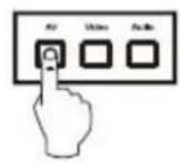
"AV" AV synchronous button: To transfer video and audio signals synchronously by the switcher.
Example: To transfer both the video and the audio signals from input channel No.3 to output channel No.6.
Operation: Press buttons in the following order "3", "AV", "6", "END", "ENTER"
"VIDEO" Video button: To transfer only video signals from input channel to output channel.
Example: To transfer video signals from input channel No.3 to output channel No.10.
Operation: Press buttons in the following order "3", "VIDEO", "1", "0", "END", "ENTER"
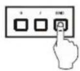
"AUDIO" Audio button: To transfer only audio signals from input channel to output channel.
Example: To transfer audio signals from input channel No.12 to output channel No.6.
Operation: Press buttons in the following order "1", "2", "AUDIO", "6", "END", "ENTER"
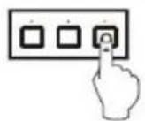
" / " Break button: To break different channels in a command
Example: To transfer video and audio signals from input channel No.1 to output
Channel No.2, 13, 6 at the same time
Operation: Press buttons in the following order "1", "AV", "2", "/", "1", "3", "/", "6", "END", "ENTER"
"END" Ending command button: Use when the command input has been finished.
"ENTER" Execute Command: To perform a command after inputting it
"ALL" All button: To transfer an input channel to all output channels or switch off all output channels.
Example 1: To transfer video and audio signals from input channel No.7 to all output channels
Operation: Press buttons in the following order "7", "ALL"
Note: Commands "END" & "ENTER" do not need to be used after this command.
Example 2: To transfer all input signals to the corresponding output channels
In another word, to switch to this status: 1->1, 2->2, 3->3, 4->4.....16->16.
Operation: Press buttons in the following order "ALL", "1"
Example 3: To switch off all the output channels.
Operation: Press buttons in the following order "ALL", "2"
"SAVE" Save button: To save the present operation to a preset command
Example: To save the present operation to the preset command No.2
Operation: Press buttons in the following order "SAVE", "2"
Note: There are altogether 10 preset commands ranged from No.0 to No.10.
"RECALL" Recall button: To recall the preset command
Example: To recall the preset command No.2
Operation: Press buttons in the following order "RECALL", "2"
"CANCEL" Cancel button: To return to the standby status without performing any commands.
Example: To cancel the input instructions "1", "AV", "2", "END"
Operation: Just press the "CANCEL" button after the above inputs.
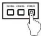
"STATUS" Inquiring status button: To inquire the present status
Example1: To inquire the status of output channel No.7
Operation: Press buttons in the following order "7", "STATUS"
Example2: To inquire the status of all the output channels one by one
Operation: Press the "STATUS" button.
"UNDO" Undo button: To resume to the previous status of the command.
"PROGRAM" Group programming button: To define, recall and clear a group of output channels.
Example 1: To group the output channels No.1, 2,3,4,5 under the Group 1
Operation: Press buttons in the following order "1", "Program", "Program", "1", "2", "3", "4", "5"
Example 2: To transfer signal from input channel No.1 to Group 2
Operation: Press buttons in the following order "1", "Program", "2"
Example 3: To clear the output channels under Group 1
Operation: Press buttons in the following order "1", "Program", "0"
Note: Please clear the group to be set before grouping it.

Backspace button: To erase the last input entry that was entered.
"THROUGH" Through button: To transfer signals directly to the corresponding output channels. Example: To transfer signals from input channels No.1, 2, 3 to their corresponding output channels. Operation: Press buttons in the following order "1", "/", "2", "/", "3", "THROUGH"
"CLOSE" Close button: To switch off the output channels Example: To switch off the output channels No.1, 2 Operation: Press buttons in the following order "1", "END", "2", "END", "CLOSE"
"LOCK" Lock button: To lock buttons on the front control panel hold it for 3 seconds. Note: When the control panel is being locked, the switcher still can be controlled via RS232 port. To unlock it, a password is needed.
"DEMO" Demo button: To demonstrate the commands one by one every 3 seconds. The Switch can be controlled directly by entering the following command: "Input Channel" + "Switching Mode" + "Output Channel" + "END" + "ENTER"


1、Press the button for input channel number "1" Display feedback on LCD: "1"

2、Press the button for switching mode "AV" Display feedback on LCD: "B" for the switching mode of video and audio ("A" for the switching mode of audio only; "V" for the switching mode of video only)


3、Press the button for the first output channel number "3" Display feedback on LCD: "3"


4、Press the break button"/" Display feedback on LCD: ", " for a break between two channels in a command


- Press the button for the second output channel number "4" Display feedback on LCD: "4"

6、Press the button "END" to finish the command Display feedback on LCD: "."


7、Press the button "ENTER" to perform this command Display feedback on LCD: "Switch OK"
Example 2: To inquire the status on the output channel No.4 Operation: Press buttons in this order "4", "STATUS"

Display feedback on LCD: The video signal of output channel No.4 is transferred from the input channel No.3 and the audio signal is from the input channel No.2
The Matrix can be controlled with the infrared remote control. The function buttons on the remote are the same as the ones on the front control panel, the remote uses the same commands and in the same order you would input them.

text_image
AV 1 2 3 4 5 6 7 8 9 0 / END END ALL CONTROL CLICK SAVE WRITE READS FREEOPERATION OF APPLICATION SOFTWARE
Switcher 2.0 is a switcher control application compatible with switchers with different inputs and outputs.
Requirements to run the software
Operating System: Window98/2000/NT/XP/Vista/7
Memory: At least 32M
Space in hard disk: At least 10M
CD-ROM
COM Port
Users can select and operate at different function tabs such as:
SYSTEM, AUTO, KEYBOARD, CUSTOM CODE, CODE GROUP and SEND/RECEIVE CODE LIST.
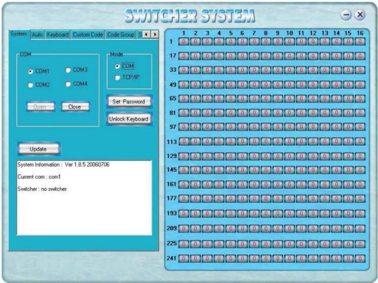
text_image
SWITCHER SYSTEM System Auto Keyboard Custom Code Code Group S COM COM1 COM3 COM2 COM4 Open Close Mode COM TCP/IP Set Password Unlock Keyboard Update System Information: Ver 1.8.5 20060706 Current com: com1 Switcher: no switcher 1 2 3 4 5 6 7 8 9 10 11 12 13 14 15 16 1 0 0 0 0 0 0 0 0 0 0 0 0 0 0 0 0 17 0 0 0 0 0 0 0 0 0 0 0 0 0 0 0 0 33 0 0 0 0 0 0 0 0 0 0 0 0 0 0 0 0 49 0 0 0 0 0 0 0 0 0 0 0 0 0 0 0 65 0 0 0 0 0 0 0 0 0 0 0 0 0 0 0 81 0 0 0 0 0 0 0 0 0 0 0 0 0 0 0 97 0 0 0 0 0 0 0 0 0 0 0 0 0 0 0 113 0 0 0 0 0 0 0 0 0 0 0 0 0 0 129 0 0 0 0 0 0 0 0 0 0 0 0 0 0 145 0 0 0 0 0 0 0 0 0 0 0 0 0 161 0 0 0 0 0 0 0 0 0 0 0 0 177 0 0 0 0 0 0 0 0 0 0 0 193 225 241 129 145 161 177 225 241On the right hand side of the main window, there are 256 buttons representing the 256 output channels. When clicking on the button output 1, the text OutPort 1 will appear
"SIGNAL": Select the switching mode "AV", "VIDEO" and "AUDIO"
"INPUT A/V PORT": Select an input A/V channel
"INPUT AUDIO PORT": Select an input audio channel\
Once the selections have been entered, click "OK"
"MODE": Select the communication mode between "COM" or "TCP/IP"
"COM": Select a COM port to control the switcher (if selecting "TCP/IP" as the communication mode, a sub-page will appear to input the IP address of the switcher)
"Set Password": Set the password for the control panel on the Matrix (The password must be an 8 digit number)
"Unlock Keyboard": Unlock the keyboard of the control panel on the Matrix.
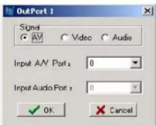
text_image
OutPort 1 Signal AV Video Audio Input A/V Port: 0 Input Audio Port: 0 OK CancelKEYBOARD TAB
Because the function buttons on this tab are the same with the ones on the front control panel, it shares the same control operation and command format with the control panel.
Please refer to the details in Chapter 7: Operation of the Control Panel

text_image
SWITCHER SYSTEM System Auto Knobard Custom Code Code Group Keyboard AV VIDEO AUDIO ENTER ALL SAVE 1 2 3 PROGRAM THROUGH RECALL 4 5 6 UNDO CLOSE STATUS 7 8 9 ← LOCK DEMO 0 / END CANCEL < Clear Feedback Message:AUTO TAB
This tab is used to test the switcher after connecting it to all the input and output devices. For example, to test the function of an RGB64X32 matrix switcher, the Auto Tab is set as below after finishing all the connection.
Switch Mode: "AV"
INPUT: From 1 to 64
OUTPUT: From 1 to 32
Delay: 1000ms (1 second)
Click on the "START" button to perform the test, the matrix switcher will:
Transfer the signals from input channel No.1 to output channel No.1-32;
Transfer the signals from input channel No.2 to output channel No.1-32;
Transfer the signals from the input channel No.64 to the output channel No.1-32;
This switching test will perform this way one by one every second until the test is over.
CUSTOM CODE TAB

text_image
SWITCHER SYSTEM System Auto Keyboard Custom Code Code Group Code: ASCII HEX Help Send Feedback Message : Clear 1 1 2 3 4 5 6 7 8 9 10 11 12 13 14 15 16 1 0 0 0 0 0 0 0 0 0 0 0 0 0 0 0 17 0 0 0 0 0 0 0 0 0 0 0 0 0 0 0 33 0 0 0 0 0 0 0 0 0 0 0 0 0 0 0 49 0 0 0 0 0 0 0 0 0 0 0 0 0 0 0 65 0 0 0 0 0 0 0 0 0 0 0 0 0 0 0 81 0 0 0 0 0 0 0 0 0 0 0 0 0 0 0 97 0 0 0 0 0 0 0 0 0 0 0 0 0 0 0 113 0 0 0 0 0 0 0 0 0 0 0 0 0 0 0 129 0 0 0 0 0 0 0 0 0 0 0 0 0 0 0 145 0 0 0 0 0 0 0 0 0 0 0 0 0 0 0 161 0 0 0 0 0 0 0 0 0 0 0 0 0 0 0 177 0 0 0 0 0 0 0 0 0 0 0 0 0 0 0 193 0 0 0 0 0 0 0 0 0 0 0 0 0 0 209 N,N,N,N,N,N,N,N,N,N,N,N,N,N,N,N,N,N,N,N,N,N,N,N,N,N,N,N,N,N,N,N,N,N,N,N,N,N,N,N,N,N,N,N,N,N,N,N,N,N,N,N,N,N,N,N,N,N,N,N,N,N,N,N,N,N,N,N,N,N,N,N,N,N,N,N,N,N,N,N,N,N,N,N,N,N,N,N,N,N,N,N,N,N,N,N,N,N,N,N,N,n,Q,R,R,R,R,R,R,R,R,R,R,R,R,R,R,R,R,R,R,R,R,R,R,R,R,R,R,R,R,R,R,R,R,R,R,R,R,R,R,R,R,R,R,R,R,R,R,R,R,R,R,R,R,R,R,R,R,R,R,R,R,R,R,R,R,R,R,R,R,R,R,R,R,R,R,R,R,R,R,R,R,R,R,R,R,R,R,R,R,R,R,R,R,R,R,R,R,R,R,R,R,r,M,M,M,M,M,M,M,M,M,M,M,M,M,M,M,M,M,M,M,M,M,M,M,M,M,M,M,M,M,M,M,M,M,M,M,M,M,M,M,M,M,M,M,M,M,M,M,M,M,M,M,M,M,M,M,M,M,M,M,M,M,M,M,M,M,M,M,M,M,M,M,M,M,M,M,M,M,M,M,M,M,M,M,M,M,M,M,M,M,M,M,M,M,M,M,m,m,m,m,m,m,m,m,m,m,m,m,m,m,m,m,m,m,m,m,m,m,m,m,m,m,m,m,m,m,m,m,m,m,m,m,m,m,m,m,m,m,m,m,m,m,m,m,m,m,m,m,m,m,m,m,m,m,m,m,m,m,m,m,m,m,m,m,m,m,m,m,m,m,m,m,m,m,m,m,m,m,m,m,m,m,m,m,m,m,m,m,m,m,m,m,m,m,m,m;m,k,k,k,k,k,k,k,k,k,k,k,k,k,k,k,k,k,k,k,k,k,k,k,k,k,k,k,k,k,k,k,k,k,k,k,k,k,k,k,k,k,k,k,k,k,k,k,k,k,k,k,k,k,k,k,k,k,k,k,k,k,k,k,k,k,k,k,k,k,k,k,k,k,k,k,k,k,k,k,k,k,k,k,k,k,k,k,k,k,k,k,k,k,k,k,k,k,k,k,k,l,L,L,L,L,L,L,L,L,L,L,L,L,L,L,L,L,L,L,L,L,L,L,L,L,L,L,L,L,L,L,L,L,L,L,L,L,L,L,L,L,L,L,L,L,L,L,L,L,L,L,L,L,L,L,L,L,L,L,L,L,L,L,L,L,L,L,L,L,L,L,L,L,L,L,L,L,L,L,L,L,L,L,L,L,L,L,L,L,L,L,L,L,L,L,L,L,L,L,L,L,l,l,l,l,l,l,l,l,l,l,l,l,l,l,l,l,l,l,l,l,l,l,l,l,l,l,l,l,l,l,l,l,l,l,l,l,l,l,l,l,l,l,l,l,l,l,l,l,l,l,l,l,l,l,l,l,l,l,l,l,l,l,l,l,l,l,l,l,l,l,l,l,l,l,l,l,l,l,l,l,l,l,l,l,l,l,l,l,l,l,l,l,l,l,l,l,l,l,l,l-l,p,r,r,r,r,r,r,r,r,r,r,r,r,r,r,r,r,r,r,r,r,r,r,r,r,r,r,r,r,r,r,r,r,r,r,r,r,r,r,r,r,r,r,r,r,r,r,r,r,r,r,r,r,r,r,r,r,r,r,r,r,r,r,r,r,r,r,r,r,r,r,r,r,r,r,r,r,r,r,r,r,r,r,r,r,r,r,r,r,r,r,r,r,r,r,r,r,r,r,r,r,u,v,v,v,v,v,v,v,v,v,v,v,v,v,v,v,v,v,v,v,v,v,v,v,v,v,v,v,v,v,v,v,v,v,v,v,v,v,v,v,v,v,v,v,v,v,v,v,v,v,v,v,v,v,v,v,v,v,v,v,v,v,v,v,v,v,v,v,v,v,v,v,v,v,v,v,v,v,v,v,v,v,v,v,v,v,v,v,v,v,v,v,v,v,v,v,v,v,v,v,v-v,w,x,y,x,y,x,y,x,y,x,y,x,y,x,y,x,y,x,y,x,y,x,y,x,y,x,y,x,y,x,y,x,y,x,y,x,y,x,y,x,y,x,y,x,y,x,y,x,y,x,y,x,y,x,y,x,y,x,y,x,y,x,y,x,y,x,y,x,y,x,y,x,y,x,y,x,y,x,y,x,y,x,y,x,y,x,y,x,y,x,y,x,y,x,y,x,y,x,y,x,y,x-y,w,x-y,w-y,w-y,w-y,w-y,w-y,w-y,w-y,w-y,w-y,w-y,w-y,w-y,w-y,w-y,w-y,w-y,w-y,w-y,w-y,w-y,w-y,w-y,w-y,w-y,w-y,w-y,w-y,w-y,w-y,w-y,w-y,w-y,w-y,w-y,w-y,w-y,w-y,w-y,w-y,w-y,w-y,w-y,w-y,w-y,w-y,w-y,w-y,w-y,w-y,w-y-w,g,h,h,h,h,h,h,h,h,h,h,h,h,h,h,h,h,h,h,h,h,h,h,h,h,h,h,h,h,h,h,h,h,h,h,h,h,h,h,h,h,h,h,h,h,h,h,h,h,h,h,h,h,h,h,h,h,h,h,h,h,h,h,h,h,h,h,h,h,h,h,h,h,h,h,h,h,h,h,h,h,h,h,h,h,h,h,h,h,h,h,h,h,h,h,h,h,h,h,h,h:h,g,h,h,h,h,h,h,h,h,h,h,h,h,h,h,h,h,h,h,h,h,h,h,h,h,h,h,h,h,h,h,h,h,h,h,h,h,h,h,h,h,h,h,h,h,h,h,h,h,h,h,h,h,h,h,h,h,h,h,h,h,h,h,h,h,h,h,h,h,h,h,h,h,h,h,h,h,h,h:h,g,g,g,g,g,g,g,g,g,g,g,g,g,g,g,g,g,g,g,g,g,g,g,g,g,g,g,g,g,g,g,g,g,g,g,g,g,g,g,g,g,g,g,g,g,g,g,g,g,g,g,g,g,g,g,g,g,g,g,g,g,g,g,g,g,g,g,g,g,g,g,g,g,g,g,g,g,g,g,g,g,g,g,g,g,g,g,g,g,g,g,g,g,g,g,g,g,g,g,g,G,H,g,H,G,H,G,H,G,H,G,H,G,H,G,H,G,H,G,H,G,H,G,H,G,H,G,H,G,H,G,H,G,H,G,H,G,H,G,H,G,H,G,H,G,H,G,H,G,H,G,H,G,H,G,H,G,H,G,H,G,H,G,H,G,H,G,H,G,H,G,H,G,H,G,H,G,H,G,H,G,H,G,H,G,H,G,H,G,H,G,H,G,H,G,H,G,H,G,H,G,H,G,H G,H,G,H,G,H,G,H,G,H,G,H,G,H,G,H,G,H,G,H,G,H,G,H,G,H,G,H,G,H,G,H,G,H,G,H,G,H,G,H,G,H,G,H,G,H,G,H,G,H,G,H,G,H,G,H,G,H,G,H,G,H,G,H,G,H,G,H,G,H,G,H,G,H,G,H,G,H,G,H,G,H,G,H,G,H,G,H,G,H,G,H,G,H,G,H,G,H,G,HG,A,K,K,K,K,K,K,K,K,K,K,K,K,K,K,K,K,K,K,K,K,K,K,K,K,K,K,K,K,K,K,K,K,K,K,K,K,K,K,K,K,K,K,K,K,K,K,K,K,K,K,K,K,K,K,K,K,K,K,K,K,K,K,K,K,K,K,K,K,K,K,K,K,K,K,K,K,K,K,K,K,K,K,K,K,K,K,K,K,K,K,K,K,K,K,K,K,K,K,K,K,E,F,E,F,E,F,E,F,E,F,E,F,E,F,E,F,E,F,E,F,E,F,E,F,E,F,E,F,E,F,E,F,E,F,E,F,E,F,E,F,E,F,E,F,E,F,E,F,E,F,E,F,E,F,E,F,E,F,E,F,E,F,E,F,E,F,E,F,E,F,E,F,E,F,E,F,E,F,E,F,E,F,E,F,E,F,E,F,E,F,E,F,E,F,E,F,E,F,E,F,E,f,E,F,E,F,E,F,E,F,E,F,E,F,E,F,E,F,E,F,E,F,E,F,E,F,E,F,E,F,E,F,E,F,E,F,E,F,E,F,E,F,E,F,E,F,E,F,E,F,E,F,E,F,E,F,E,F,E,F,E,F,E,F,E,F,E,F,E,F,E,F,E,F,E,F,E,F,E,F,E,F,E,F,E,F,E,F,E,F,E,F,E,F,E,F,E,F,E,F,E,e,f,e,f,e,f,e,f,e,f,e,f,e,f,e,f,e,f,e,f,e,f,e,f,e,f,e,f,e,f,e,f,e,f,e,f,e,f,e,f,e,f,e,f,e,f,e,f,e,f,e,f,e,f,e,f,e,f,e,f,e,f,e,f,e,f,e,f,e,f,e,f,e,f,e,f,e,f,e,f,e,f,e,f,e,f,e,f,e,f,e,f,e,f,e,f,e,f,e,f,e+f,e,f,e,f,e,f,e,f,e,f,e,f,e,f,e,f,e,f,e,f,e,f,e,f,e,f,e,f,e,f,e,f,e,f,e,f,e,f,e,f,e,f,e,f,e,f,e,f,e,f,e,f,e,f,e,f,e,f,e,f,e,f,e,f,e,f,e,f,e,f,e,f,e,f,e,f,e,f,e,f,e,f,e,f,e,f,e,f,e,f,e,f,e,f,e,f,e,f,e:f,c,d,d,d,d,d,d,d,d,d,d,d,d,d,d,d,d,d,d,d,d,d,d,d,d,d,d,d,d,d,d,d,d,d,d,d,d,d,d,d,d,d,d,d,d,d,d,d,d,d,d,d,d,d,d,d,d,d,d,d,d,d,d,d,d,d,d,d,d,d,d,d,d,d,d,d,d,d,d,d,d,d,d,d,d,d,d,d,d,d,d,d,d,d,d,d,d,d,d,d,d,D,D,D,D,D,D,D,D,D,D,D,D,D,D,D,D,D,D,D,D,D,D,D,D,D,D,D,D,D,D,D,D,D,D,D,D,D,D,D,D,D,D,D,D,D,D,D,D,D,D,D,D,D,D,D,D,D,D,D,D,D,D,D,D,D,D,D,D,D,D,D,D,D,D,D,D,D,D,D,D,D,D,D,D,D,D,D,D,D,D,D,D,D,D,D,D,D,D,D,D D,P,P,P,P,P,P,P,P,P,P,P,P,P,P,P,P,P,P,P,P,P,P,P,P,P,P,P,P,P,P,P,P,P,P,P,P,P,P,P,P,P,P,P,P,P,P,P,P,P,P,P,P,P,P,P,P,P,P,P,P,P,P,P,P,P,P,P,P,P,P,P,P,P,P,P,P,P,P,P,P,P,P,P,P,P,P,P,P,P,P,P,P,P,P,P,P,P,P,P,P:P,P,P,P,P,P,P,P,P,P,P,P,P,P,P,P,P,P,P,P,P,P,P,P,P,P,P,P,P,P,P,P,P,P,P,P,P,P,P,P,P,P,P,P,P,P,P,P,P,P,P,P,P,P,P,P,P,P,P,P,P,P,P,P,P,P,P,P,P,P,P,P,P,P,P,P,P,P,P,P,P,P,P,P,P,P,P,P,P,P,P,P,P,P,P,P,P,P,P,P,p,p,p,p,p,p,p,p,p,p,p,p,p,p,p,p,p,p,p,p,p,p,p,p,p,p,p,p,p,p,p,p,p,p,p,p,p,p,p,p,p,p,p,p,p,p,p,p,p,p,p,p,p,p,p,p,p,p,p,p,p,p,p,p,p,p,p,p,p,p,p,p,p,p,p,p,p,p,p,p,p,p,p,p,p,p,p,p,p,p,p,p,p,p,p,p,p,p,p,p.p,n,O,O,O,O,O,O,O,O,O,O,O,O,O,O,O,O,O,O,O,O,O,O,O,O,O,O,O,O,O,O,O,O,O,O,O,O,O,O,O,O,O,O,O,O,O,O,O,O,O,O,O,O,O,O,O,O,O,O,O,O,O,O,O,O,O,O,O,O,O,O,O,O,O,O,O,O,O,O,O,O,O,O,O,O,O,O,O,O,O,O,O,O,O,O,O,O,O,O,O,O,U,o,o,o,o,o,o,o,o,o,o,o,o,o,o,o,o,o,o,o,o,o,o,o,o,o,o,o,o,o,o,o,o,o,o,o,o,o,o,o,o,o,o,o,o,o,o,o,o,o,o,o,o,o,o,o,o,o,o,o,o,o,o,o,o,o,o,o,o,o,o,o,o,o,o,o,o,o,o,o,o,o,o,o,o,o,o,o,o,o,o,o,o,o,o,o,o,o,o,o,o,n,o,o,o,n,o,o,n,o,o,n,o,o,n,o,n,o,n,o,n,o,n,o,n,o,n,o,n,o,n,o,n,o,n,o,n,o,n,o,n,o,n,o,n,o,n,o,n,o,n,o,n,o,n,o,n,o,n,o,n,o,n,o,n,o,n,o,n,o,n,o,n,o,n,o,n{o},Select between ASCII and HEX format command codes
Help: Displays the list of command codes.
Send: Sends out the typed command codes.
For example, to transfer the video and audio signals from the input channel No.1 to the output channel No.7, and the audio signals from the input channel No.2 to the output channel No.4, just perform the following steps below.
- Select the "ASCII" as the command codes format;
- Input the command codes "1B7.2A4."
- Click the button "Send" to perform the commands.
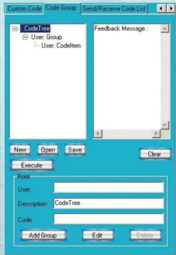
CODE GROUP TAB
SWITCHER SYSTEM

text_image
Custom Code Code Group Send/Receive Code List CodeTree User: Group User: Codeltem Feedback Message : New Open Save Clear Execute Root User: Description: CodeTree Code: Add Group Edit Delete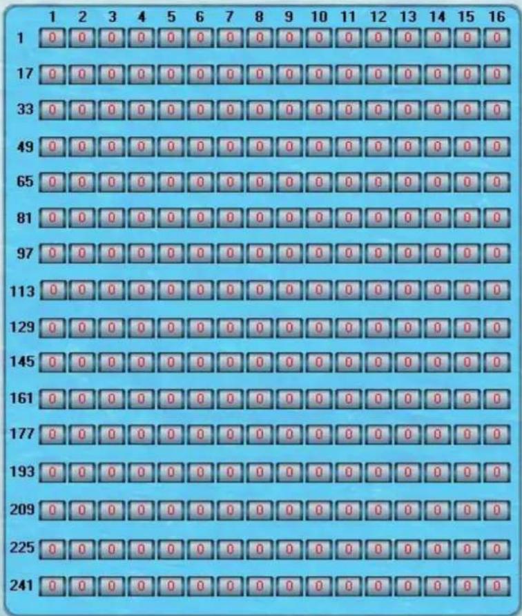
text_image
1 2 3 4 5 6 7 8 9 10 11 12 13 14 15 16 1 0 0 0 0 0 0 0 0 0 0 0 0 0 0 0 0 0 17 0 0 0 0 0 0 0 0 0 0 0 0 0 0 0 0 0 33 0 0 0 0 0 0 0 0 0 0 0 0 0 0 0 0 0 49 0 0 0 0 0 0 0 0 0 0 0 0 0 0 0 0 65 0 0 0 0 0 0 0 0 0 0 0 0 0 0 0 81 0 0 0 0 0 0 0 0 0 0 0 0 0 0 0 97 0 0 0 0 0 0 0 0 0 0 0 0 0 0 113 0 0 0 0 0 0 0 0 0 0 0 0 0 0 129 0 0 0 0 0 0 0 0 0 0 0 0 0 145 0 0 0 0 0 0 0 0 0 0 0 0 161 0 0 0 0 0 0 0 0 0 0 0 177 0 0 0 0 0 0 0 0 0 0 193 0 0 0 0 0 0 0 0 0 225 241 241New: Create a new group of preset commands
Open: Opens a group of preset commands
Save: Saves the present group of preset commands
Execute: Execute a selected preset command or a selected group of preset commands
Clear: Clears the feedback window
Add Code Item: To add another new group of preset commands
Edit: To edit the User's name (User),
Delete: Deletes the selected group.
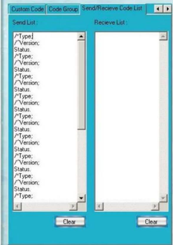
SEND / RECIEVE CODE LIST TAB
SWITCHER SYSTEM

text_image
Custom Code Code Group Send/Receive Code List Send List : /*Type; /*Version; Status. /*Type; /*Version; Status. /*Type; /*Version; Status. /*Type; /*Version; Status. /*Type; /*Version; Status. /*Type; /*Version; Status. /*Type; /*Version; Status. /*Type; /*Version; Status. /*Type; /*Version; Status. /*Type; /*Version; Status. /*Type; /*Version; Status. /*Type; /*Version; Status. /*Type; /*Version; Status. /*Type; *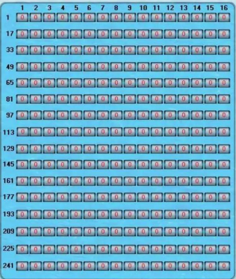
text_image
1 2 3 4 5 6 7 8 9 10 11 12 13 14 15 16 1 0 0 0 0 0 0 0 0 0 0 0 0 0 0 0 0 17 0 0 0 0 0 0 0 0 0 0 0 0 0 0 0 0 33 0 0 0 0 0 0 0 0 0 0 0 0 0 0 0 0 49 0 0 0 0 0 0 0 0 0 0 0 0 0 0 0 65 0 0 0 0 0 0 0 0 0 0 0 0 0 0 0 81 0 0 0 0 0 0 0 0 0 0 0 0 0 0 0 97 0 0 0 0 0 0 0 0 0 0 0 0 0 0 113 0 0 0 0 0 0 0 0 0 0 0 0 0 0 129 0 0 0 0 0 0 0 0 0 0 0 0 0 145 0 0 0 0 0 0 0 0 0 0 0 0 161 0 0 0 0 0 0 0 0 0 0 0 177 0 0 0 0 0 0 0 0 0 0 0 193 0 0 0 0 0 0 0 0 0 0 225 241 241Send List window: Lists sent command code
Received List window: Lists feedback from the switcher
Clear: Clears either of the two lists
SEND / RECIEVE CODE LIST TAB
With the application "Switcher 2.00" one is able to control and operate the RGB Matrix remotely Communication protocol:
Baud rate: 9600 Data bit: 8 Stop bit: 1 Parity bit: none
| Command Types Command Codes Functions | ||
| System Command /*Type; Acquires the models information. | ||
| /+xxxxxxxx; Rewrites the passwords: must be 8 digits. | ||
| /%Lock; Locks the keyboard. | ||
| /%Unlock; Unlocks the keyboard. | ||
| /:BellOff; Turn off the buzzer. | ||
| /:BellOn; Turn on the buzzer. | ||
| /^Version; Acquires the version of software | ||
| /~CREATOR20; Switch to CREATOR2.0 command system. | ||
| [x1]All Transfer signals from input channel [x1] to all output channels | ||
| Operation Command All# Transfer all input signals to matching output channels. | ||
| AllSwitch off all output channels. | ||
| [x1]# Transfer signals from input channel [x1] to output channel [x1]. | ||
| [x1] [x1]. Switch off output channel [x1]. | ||
| [x1] V[x2] | Transfer the video signals from input channel [x1] to output channel [x2]. | |
| [x1] V[x2],[x3],[x4] | Transfer the video signals from input channel [x1] to output channels [x2], [x3] and [x4]. | |
| [x1] A[x2] | Transfer the audio signals from input channel [x1] to output channel [x2]. | |
| [x1] A[x2],[x3],[x4] | Transfer the audio signals from input channel [x1] to output channels [x2], [x3] and [x4]. | |
| [x1] B[x2] | Transfer both video and audio signals from input channel [x1] to output channel [x2]. | |
| [x1] B[x2],[x3],[x4] | Transfer both video and audio signals from input channel [x1] to output channels [x2], [x3] and [x4]. | |
| [x1]P[x2] Transfer signals from input channel [x1] to all output channels in group [x2]. | ||
| [x1]PP[x2],[x3],[x4] | Group output channels [x2], [x3] and [x4] under group [x1]. | |
| S[x] | Acquires the output channels in Group[x]. | |
| Status[x1] | Acquires the input channel to the output channel [x1]. | |
| Status | Acquires the input channel to the output channels one by one. | |
| Save[Y] Save the present operation to the preset command [Y]. [Y] ranges from 0 to 9. | ||
| Recall[Y] Recall the preset command [Y]. | ||
| Clear[Y] | Clear the preset command [Y]. | |
| [X1]*[X2]! | Transfer both video and audio signals from input channel [x1] to output channel [x2]. | |
| [X1]*[X2] | Transfer audio signals from input channel [x1] to output channel [x2]. | |
| [X1]*[X2]% | Transfer video signals from input channel [x1] to output channel [x2]. | |
| [X1]*[X2]& | Transfer video signals from input channel [x1] to output channel [x2]. | |
TECHNICAL SPECIFICATIONS
| Specifications / Models Matrix RGB8 Series Matrix RGB16 Series Matrix RGB64, 48 Series | |
| Video | |
| Gain 0 dB | |
| Bandwidth 450MHz (-3dB), fully loaded | 0 -10MHz @ ± 0.1dB0 -100MHz @ ± 0.6dB |
| Cross Talk Sum 56dB@10M, -40dB@100M | |
| Differential Phase I/OS <1.28°, 3.58MH | |
| Differential Gain Error 0.1°, 3.58-4.43MHz | |
| Differential Gain Error 0.1%, 3.58-4.43MHz | |
| Max Transfer Delay 5nS(±1nS) | |
| Switching Speed 200 ns (Max) | |
| Signal type RGBHV, RGBS, RGsB, RsGsBs, HDTV, Component video,S-video,Composite video | |
| Input video | |
| Connector BNC female | |
| Signal Strength 1V p-p Y component video, S-video, composite video; 0.7V p-p RGB;0.3V p-p R-Y & B-Y compo-nent video, S-video | |
| Maximum/MinimumLevel | Analog signals: 0.5V ~ 2.0V p-p |
| Impedance 75 Ω | |
| Echo loss | -30dB@5MHz |
| Max Error in DC Offset | 15mV |
| Output video | |
| Connector BNC female | |
| Maximum/MinimumLevel | 2.0V p-p |
| Impedance 75 Ω | |
| Echo loss | -30dB@5MHz |
| Max Compensation inDC Offset | ±5mV |
| Sync Signal | |
| Input/Output Signals | RGBHV, RGBS, RGsB, RsGsBs |
| Input Level | 0.5V- 5.0V p-p,: 4.0V p-p normal |
| Output Level | AGC-TTL: 5Vp-p, unterminated |
| Input Impedance | 510 Ω |
| Output Impedance | 75 Ω |
| Polarity | Straight or subtractive according to input |
TABLE OF CONTENTS
| Specifications / Models Matrix RGB8 Series Matrix RGB16 Series Matrix RGB64, 48 Series | |||
| Audio Signal | |||
| I/O Connector 3.8mm with screw, 5 pole | |||
| Gain 0dB | |||
| Frequency Respond 20 Hz ~ 20 kHz | |||
| General Harmonic Distortion + Noise | 0.03% @ 1 kHz (under rating voltage) | ||
| S/N >90dB | |||
| Segregation Rate >80dB @ 1 kHz | |||
| CMRR >75dB @: 20 Hz ~ 20 kHz | |||
| Signal >75dB @: 20 Hz ~ 20 kHz | |||
| Impedance Input >10 k Ω (balanced /unbalanced) Output 50 Ω (unbalanced), 100 Ω (balanced) | |||
| Maximum Input Level +19.5dBu, (balanced /unbalanced) | |||
| Gain error ±0.1dB | |||
| Max Output Level +19.5dBu, (balanced /unbalanced) | |||
| Control type | |||
| Serial Control Port RS-232, 9-pin FD connector | |||
| Baud Rate and Protocol | Baud rate: 9600 Data bit: 8 Stop bit: 1 Parity bit: none | ||
| Serial Control Poling Protocol | 2 = TX, 3 = RX, 5 = GND | ||
| Ethernet | Connector RJ-45 Female(Optional accessory)Protocol TCP/IPSpeed Full/half-duplex 10/100 | ||
| Control Application Switch 2.0 | |||
| Features | |||
| Power Supply | 100VAC ~ 240VAC, 50/60 Hz, universal international power supply | ||
| Temperature | Storing and operating temperature: -20° ~ +70°C | ||
| Humidity | Storing and operating humidity: 10% ~ 90% | ||
| Size | 485(L)X133(W)X266(H) | 485(L)X311(W)X266mm(H) | 485(L)X315(W)X266mm(H)(single box) |
| Weight | 4.5kg | 9.5kg | 10kg |
| MTBF | 30,000 hours | ||
| Quality Guarantee | 3 Year Warranty | ||
TROUBLESHOOTING
| Problem Solution | |
| Output image is displayed with a ghost Check display settings, try another high quality cable | |
| Color loss or no video on output signal Check both the input and output connections | |
| Remote control doesnt work Check batteries, If broken, contact dealer | |
| The switcher cannot be controlled by computer through COM port. | Check the COM port in the software.Make sure the COM is working |
| NO sound when switching with I/O signal. Make sure the beeper is switched on. If it is it maybe broken inside, contact dealer | |
| NO image on output signal Check the Input and Output connectors they may be loose. Check the connection cord it may be broken.Check the output device and make sure it is connected to the output channel. | |
| Power Indicator doesnt work, no display on LCD no response to any operation. | Check the power cord to see it is connected and not damaged. |
| Interference in the output image Check to see if the unit is well grounded. | |
| Static gets stronger when connecting BNC connetors The unit is not grounded correctly. Correct issue immediately or damage may be caused to the switch. | |
| Beeper makes sound. LCD is displaying normally and there is a returning code. But there isn't any Video or Audio output. | Check connections, and replace if damaged |
| The swticher cannot be controlled by front panel keys, RS-232 port or remote control | The unit may be broken, contact dealer for repair. |
SAFETY INFORMATION
Safeguards

To reduce the risk of electric shock, do not expose this product to rain or moisture

Do not modify the wall plug. Doing so will void the warranty and safety features.

If the wall plug does not fit into your local power socket, hire an electrician to replace your obsolete socket.
This equipment should be installed near the socket outlet and the device should be easily accessible in the case it requires disconnection.
Precautions
FCC regulations state that any unauthorized changes or modifications to this equipment, not expressly approved by the manufacturer, could void the user's authority to operate this equipment.
Operate this product using only the included external power supply. Use of other power supplies could impair performance, damage the product, or cause fires.
In the event of an electrostatic discharge this device may automatically turn off. If this occurs, unplug the device and plug it back in.
Protect and route power cords so they will not be stepped on or pinched by anything placed on or against them. Be especially careful of plug-ins or cord exit points from this product.
Avoid excessive humidity, sudden temperature changes or temperature extremes.
Keep this product away from wet locations such as bathtubs, sinks, laundries, wet basements, fish tanks, and swimming pools.
Use only accessories recommended by Atlona to avoid fire, shock, or other hazards.
Unplug the product before cleaning. Use a damp cloth for cleaning and not cleaning fluid or aerosols. Such products could enter the unit and cause damage, fire, or electric shock. Some substances may also mar the finish of the product.
Never open, remove unit panels, or make any adjustments not described in this manual. Attempting to do so could expose you to dangerous electrical shock or other hazards. It may also cause damage to your AT-RGB-MATRIX. Opening the product will void the warranty.
Do not attempt to service the unit. Disconnect the product and contact your authorized Atlona reseller or contact Atlona directly.
WARRANTY
Limited Warranty
Atlona Technologies warrants that (a) its products (the AT-RGB-MATRIX) will perform substantially in accordance with the accompanying written materials for a period of 3 years from the date of receipt and (b) that the product will be free from defects in materials and workmanship under normal use and service for a period of 3 years. In the event applicable law imposes any implied warranties, the implied warranty period is limited to 3 years from the date of receipt. Some jurisdictions do not allow such limitations on duration of an implied warranty, so the above limitation may not apply to customers that fall within those areas.
Customer Remedies
Atlona Technologies' and its suppliers' entire liability and Customer's exclusive remedy shall be, at Atlona Technologies' decision, either return of the price paid for the product, repair, or replacement of the product that does not meet this Limited Warranty and which is returned to Atlona Technologies with a copy of the Customer's receipt. This Limited Warranty is void if failure of the product has resulted from accident, abuse, misapplication, or natural occurrence. In example but not limited to: power surges (electrical storms, local power outage), dropping the product (or items on the product), contact with fluids, and physical misconduct (i.e. kicking or punching). Any replacement product will be warranted for the remainder of the original warranty period.
No other warranties
To the maximum extent permitted by applicable law, Atlona Technologies and its suppliers disclaim all other warranties, either expressed or implied, including, but not limited to, implied warranties of merchantability and fitness for a particular purpose, with regard to the product and any related written materials. This Limited Warranty gives customer specific legal rights. Customers may have other rights depending on the jurisdiction.
No liability for damages
To the maximum extent permitted by applicable law, in no event shall Atlona Technologies or its suppliers be liable for any damages arising out of the use of or inability to use this product, even if Atlona Technologies has been advised of the possibility of such damages. Such damages include but are not limited to: special, incidental, consequential, or indirect damages for personal injury, loss of business profits, business interruption, loss of business information, or any other pecuniary loss. Atlona Technologies' and its suppliers' entire liability under any provision of this agreement shall be limited to the amount actually paid by you for the product. Some Jurisdictions do not allow the exclusion or limitation of liability for consequential or incidental damage. The above limitations may not apply to you in such jurisdictional cases.
ATLONA PRODUCT REGISTRATION
Thank you for purchasing this Atlona product. - We hope you enjoy it and will take an extra few moments to register your new purchase.
Registration creates an ownership record if your product is lost or stolen and helps ensure you'll receive notification of performance issues and firmware updates.
At Atlona, we respect and protect your privacy, assuring you that your registration information is completely secure. Atlona product registration is completely voluntary and failure to register will not diminish your limited warranty rights.
To register go to: http://www.atlona.com/registration