
AT-DVI0808 - Video switch Atlona - Free user manual and instructions
Find the device manual for free AT-DVI0808 Atlona in PDF.

| Product Type | DVI Matrix Switcher |
| Model | AT-DVI0808 |
| Video Inputs | 8 x DVI-D female |
| Video Outputs | 8 x DVI-D female |
| Audio Inputs | 8 x 3.8mm screw connector (balanced/unbalanced) |
| Audio Outputs | 8 x 3.8mm screw connector (balanced/unbalanced) |
| Control Methods | Front panel, IR remote, RS-232, PC software (Switcher 2.0), 3rd party control |
| Video Bandwidth | 165 MHz (all digital) |
| Maximum Resolution | 1920 x 1200 |
| Switching Speed | 200 ns (longest time) |
| Video Signal Type | DVI-D digital T.M.D.S. (non-HDCP) |
| Audio Frequency Response | 20 Hz - 20 kHz |
| Audio S/N Ratio | >90 dB |
| Power Supply | 100-240 VAC, 50/60 Hz (universal) |
| Dimensions (L x W x H) | 430 x 260 x 133.5 mm |
| Weight | 4.2 kg |
| Rack Mountable | Yes (19-inch, 1U recommended spacing) |
| Operating Temperature | -20°C to +70°C |
| Operating Humidity | 10% to 90% (non-condensing) |
| MTBF | 30,000 hours |
| Warranty | 3 years |
| Safety Precautions | Use only included power supply; do not open cover; ensure ventilation; avoid liquids |
| Maintenance | Keep dry; clean with soft cloth; no liquid cleaners |
| Spare Parts / Repairability | No user-serviceable parts; contact dealer for repair |
| Included Accessories | RS-232 cable, power supply, user manual, CD with software |
Frequently Asked Questions - AT-DVI0808 Atlona
User questions about AT-DVI0808 Atlona
0 question about this device. Answer the ones you know or ask your own.
Ask a new question about this device
Download the instructions for your Video switch in PDF format for free! Find your manual AT-DVI0808 - Atlona and take your electronic device back in hand. On this page are published all the documents necessary for the use of your device. AT-DVI0808 by Atlona.
USER MANUAL AT-DVI0808 Atlona
Safety Operation Guide:
1.0 Safety Operation Guide
\*\*\*\*\*\*\*\*\*\*\*\*\*\*\*\*\*\*\*\*\*\*\*\*\*\*\*\*\*\*\*\*\*\*\*\*\*\*\*\*\*\*\*\*\*\*\*\*\*\*\*\*\*\*\*\*\*\*\*\*\*\*\*\*\*\*\*\*\*\*\*\*\*\*\*\*\*\*\*\*\*\*\*\*\*\*\*\*\*\*
In order to ensure the credibility and the user's safety, please comply with the following items during installation, maintenance and operation of the switch.
1) The switch must be in stable position. Use only the power supply that comes with unit. Do not use an alternate as it may damage it.
2) Do not place the switcher near hot or cold surfaces or sources.
3) To avoid any damage by over heating, please keep the environment in good ventilation to radiate the heat when running the switcher.
4) The switcher should be turned off when it is not used.
5) Please do not attempt to take cover off the switcher for there is a high-volt age component inside that could cause electric shock.
6) Do not splash any liquid or chemical on or near the equipment.
7) Please make sure all the wiring are in working condition and are not cut or damaged.
This DVI Switchers User Manual can be used for other DVI matrix switcher models. This manual is only an instruction for operators, not for any maintenance usage. Any changes of functions and parameters since then will be informed separately. This manual is copyright Atlona Technologies. All rights reserved. No part of this publication may be copied or reproduced without the prior written consent of Atlona Technologies.
Please check Atlona website updates. http://www.Atlona.com
Contents:
Safety Operation Guide....2
- Introduction......4
1.1 About the DVI Matrix Switch....4
1.2 DVI Matrix Switch Model....4 - Package Contents....5
- Installation....5
- Front and Rear View on the Product....6
- Operation and Control......6
5.1 RS232, LAN and 3rd Party Control ....6
5.2 Connecting using Input and Output Terminals....7
5.3 Connecting and Setting up Audio....7
5.4 Front Control/ Operation....9
5.5 Remote Control Operation....12
5.6 Operation Of Application Software....12
5.7 Keyboard Tab....14
5.8 Auto Tab....14
5.9 Cusome Code Tab....15
5.10 Code Group Tab....16
5.11 Send/Receive Code List Tab....17 - Operation of RS232....17
- Technical Specifications....19
- Troubleshooting....21
1. Introduction:
1.1 About the DVI Matrix Switch
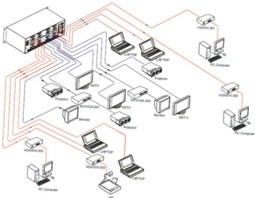
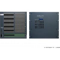
DVI series Matrix switcher is a high-performance professional computer and audio signal switcher that can be used for cross switching of multi computer and audio signals. Independent DVI component and balance/unbalance I/O terminals make each component signal transmit and switch separately; this design can reduce signal transmission to minimum and output the image and audio signal in high-fidelity quality.
DVI series switcher mostly apply in broadcasting TV engineering, multi-media meeting room, big screen display engineering, television education, command control center or other fields. It provides power-fail locale protection function, LCD displaying, A/V timing or separate switching function. It also has a adaptable compensation to extend the input distance to 70 feet. With RS232 interface, it can be worked with PC, remote control system and any other 3rd party control system devices. The user manual takes DVI0808-A as an example, other models can take reference from it too.
1.2 DVI Matrix Switch Model
| SpecificationModel | Video Inputs Video Outputs Audio Inputs Audio Outputs RS232 | ||||
| AT-DVI0808-A | 8888 | √ | |||
| AT-DVI1616-A | 16 16 16 16 | √ | |||
2. Package Contents

RS232 Communication Cable

Power Supply Cable

User Manual and Quality Guarantee

CD with Application Software for DVI Switch
3. Installation
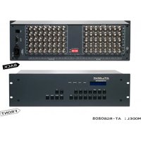
DVI matrix switchers adopt metal shell and can be stacked with other devices. They are rack-mountable and can be installed on a standard 19 inches rack. It is recommended to leave a 1U space between the units to have easy access for installation of the cables.

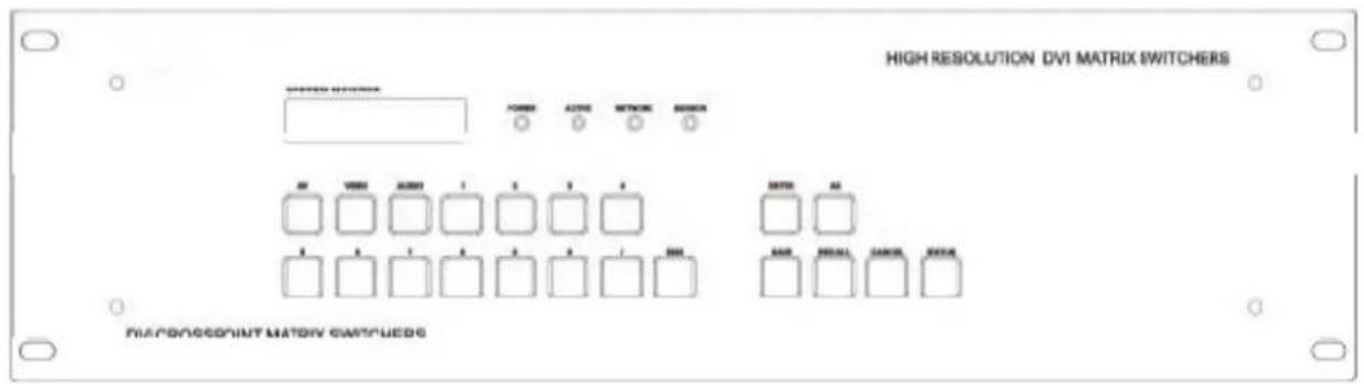
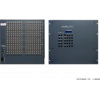
4. Front and Rear View on the Product


5. Operation and Control
5.1 RS232, LAN and 3rd Party Control
The Switchers can be controlled by front controls or PC, CRESTRON control system, AMX control system,) or through the Ethernet control via the RS-232 communication port. The RS232 is female 9-pin D connector. It can be switched by several control systems. When the switcher connects to the COM1 or COM2 of the computer with control software, users can control it by that computer. To control the switcher, users may use the application SWITCHER 2.0 in the supplied CD or develop their own control software.

This RS-232 communication port is a female 9-pin D connector. The definition of its pins is as the table below.
| No. | Pin | Function |
| 1 | N/u | Unused |
| 2 | Tx | Transmit |
| 3 | Rx | Receive |
| 4 | N/u | Unused |
| 5 | Gnd | Ground |
| 6 | N/u | Unused |
| 7 | N/u | Unused |
| 8 | N/u | Unused |
| 9 | N/u | Unused |

5.2 Connecting using Input and Output Terminals
The DVI matrix switch may take DVD players, computers, graphic workstations and other digital NON HDCP SIGNALS as their input signal source. The switch can out to projectors, video recorders, displays and other DVI NON HDCP displays depending on the application.

| PIN | function | PIN | function |
| 1 | T.M.D.S.Data** | 13 | T.M.D.S.Data3+ |
| 2 | T.M.D.S.Data++ | 14 | +5V Power |
| 3 | T.M.D.S.Data•/4 Shield | 15 | Ground (for -5V) |
| 4 | T.M.D.S.Data** | 16 | Hot Plug Detect |
| 5 | T.M.D.S.Data** | 17 | T.M.D.S.Data 0- |
| 6 | DDC Clock | 18 | T.M.D.S.Data 0+ |
| 7 | DDC Data | 19 | T.M.D.S.Data 0/5 Shield |
| 8 | No Connect | 20 | T.M.D.S.Data5- |
| 9 | T.M.D.S.Data1- | 21 | T.M.D.S.Data5+ |
| 10 | T.M.D.S.Data1+ | 22 | T.M.D.S. Clock Shield |
| 11 | T.M.D.S.Data1/3 Shield | 23 | T.M.D.S. Clock + |
| 12 | T.M.D.S.Data3* | 24 | T.M.D.S. Clock- |
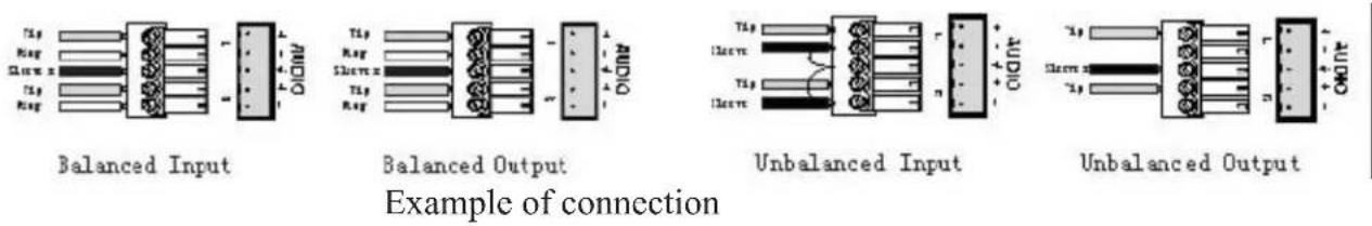
5.3 Connecting and Setting up Audio
"AUDIO INPUTS", "AUDIO OUTPUTS" audio network interface in DVI matrix switchers can be connected to the audio signal and amplify sources. Audio connection is little more complicated than video. It has two types of connection: balanced and unbalanced. The balanced connection transmits a pair of balanced signals with two cables. Because Interferences will have the same intensity and the opposite phases on the two cables; it will be counteracted in the end. For the low frequency extent of the audio signal, it would be easily interfered under long distance transmission. Therefore as an anti-interference connection, it is mostly used in Audio connection of special high end devices.
The unbalanced connection transmits signals only with one cable. Without counteraction, it can be interfered more easily. Accordingly, it is adopted for household appliance or some cases with low technical demand. Take the audio signal line for example: 1.Unbalanced: pin “G” connect to SLEEVE, pin “+” connect to TIP, pin “-” connect to pin “G”; 2.Balanced: pin “G” connect to SLEEVE, pin “-” connect to RING, pin “+” Connect to TIP.
To select which connection is up to the interface of the device. When available, the balanced Connection is the first choice.
Before connecting, please read the command or relevant demand in the user manual carefully. In some cases, there is balanced in source signal end but unbalanced in the destination end. If in a nonstandard case, it is done to connect balanced for the balanced end and unbalanced for unbalanced end. But if in a standard one, the converter must be used to switch the signals as the same, balanced or unbalanced.
flowchart
graph TD
    A["Router"] --> B["Laptop"]
    A --> C["Laptop"]
    A --> D["Laptop"]
    A --> E["Laptop"]
    A --> F["Laptop"]
    A --> G["Laptop"]
    A --> H["Laptop"]
    A --> I["Laptop"]
    A --> J["Laptop"]
    A --> K["Laptop"]
    A --> L["Laptop"]
    A --> M["Laptop"]
    A --> N["Laptop"]
    A --> O["Laptop"]
    A --> P["Laptop"]
    A --> Q["Laptop"]
    A --> R["Laptop"]
    A --> S["Laptop"]
    A --> T["Laptop"]
    A --> U["Laptop"]
    A --> V["Laptop"]
    A --> W["Laptop"]
    A --> X["Laptop"]
    A --> Y["Laptop"]
    A --> Z["Laptop"]
    A --> AA["Laptop"]
    A --> AB["Laptop"]
    A --> AC["Laptop"]
    A --> AD["Laptop"]
    A --> AE["Laptop"]
    A --> AF["Laptop"]
    A --> AG["Laptop"]
    A --> AH["Laptop"]
    A --> AI["Laptop"]
    A --> AJ["Laptop"]
    A --> AK["Laptop"]
    A --> AL["Laptop"]
    A --> AM["Laptop"]
    A --> AN["Laptop"]
    A --> AO["Laptop"]
    A --> AP["Laptop"]
    A --> AQ["Laptop"]
    A --> AR["Laptop"]
    A --> AS["Laptop"]
    A --> AT["Laptop"]
    A --> AU["Laptop"]
    A --> AV["Laptop"]
    A --> AW["Laptop"]
    A --> AX["Laptop"]
    A --> AY["Laptop"]
    A --> AZ["Laptop"]
    A --> BA["Laptop"]
    A --> BB["Laptop"]
    A --> BC["Laptop"]
    A --> BD["Laptop"]
    A --> BE["Laptop"]
    A --> BF["Laptop"]
    A --> BG["Laptop"]
    A --> BH["Laptop"]
    A --> BI["Laptop"]
    A --> BJ["Laptop"]
    A --> BK["Laptop"]
    A --> BL["Laptop"]
    A --> BM["Laptop"]
    A --> BN["Laptop"]
    A --> BO["Laptop"]
    A --> BP["Laptop"]
    A --> BQ["Laptop"]
    A --> BR["Laptop"]
    A --> BS["Laptop"]
    A --> BT["Laptop"]
    A --> BU["Laptop"]
    A --> BV["Laptop"]
    A --> BW["Laptop"]
    A --> BX["Laptop"]
    A --> BY["Laptop"]
    A --> BZ["Laptop"]
    A --> CA["Laptop"]
    A --> CB["Laptop"]
    A --> CC["Laptop"]
    A --> CD["Laptop"]
    A --> CE["Laptop"]
    A --> CF["Laptop"]
    A --> CG["Laptop"]
    A --> CH["Laptop"]
    A --> CI["Laptop"]
    A --> CJ["Laptop"]
    A --> CK["Laptop"]
    A --> CR["Laptop"]
    A --> CS["Laptop"]
    A --> CT["Laptop"]
    A --> CU["Laptop"]
    A --> CV["Laptop"]
    A --> CW["Laptop"]
    A --> CX["Laptop"]
    A --> CY["Laptop"]
    A --> CZ["Laptop"]
    A --> DA["Laptop"]
    A --> DB["Laptop"]
    A --> DC["Laptop"]
    A --> DV-LVGA-240
    DV-LVGA-240
    DV-LVGA-240
    DV-LVGA-240
    DV-LVGA-240
    DV-LVGA-240
    DV-LVGA-240
    DV-LVGA-240
    DV-LVGA-240
    DV-LVGA-240
    DV-LVGA-240

5.4 Front Control/ Operation
LCD display: Real time monitor of the operations and status
“0, 1,9” Keypad: Keys to select I/O channels and save/recall preset commands
“AV” AV synchronous button: To transfer video and audio signal synchronously by the switcher. Example: To transfer both the video and the audio signals from input channel No.3 to output channel No.6. Operation: Press buttons in the following order “3”, “AV”, “6”, “END”, “ENTER”
“VIDEO” Video button: To transfer only video signals from input channel to output channel. Example: To transfer video signals from input channel No.3 to output channel No.10. Operation: Press buttons in the following order “3”, “VIDEO”, “1”, “0”, “END”, “ENTER”
"AUDIO" Audio button: To transfer only audio signals from input channel to output channel. Example: To transfer audio signals from input channel No.12 to output channel No.6. Operation: Press buttons in the following order "1", "2", "AUDIO", "6", "END", "ENTER"
“/” Break button: To break different channels in a command Example: To transfer video and audio signals from input channel No.1 to output Channel No.2, 13, 6 at the same time Operation: Press buttons in the following order “1”, “AV”, “2”, “/”, “1”, “3”, “/”, “6”, “END”, “ENTER”
“END” Ending command button: Use when the command input has been finished.
“ENTER” Execute Command: To perform a command after inputting it
“ALL” All button: To transfer an input channel to all output channels or switch off all output channels. Example 1: To transfer video and audio signals from input channel No.7 to all output channels Operation: Press buttons in the following order “7”, “ALL” Note: Commands “END” & “ENTER” do not need to be used after this command. Example 2: To transfer all input signals to the corresponding output channels In another word, to switch to this status: 1->1, 2->2, 3->3, 4->4.....16->16. Operation: Press buttons in the following order “ALL”, “1” Example 3: To switch off all the output channels. Operation: Press buttons in the following order “ALL”, “2”
“SAVE” Save button: To save the present operation to a preset command Example: To save the present operation to the preset command No.2 Operation: Press buttons in the following order “SAVE”, “2” Note: There are altogether 10 preset commands ranged from No.0 to No.10.
“RECALL” Recall button: To recall the preset command
Example: To recall the preset command No.2
Operation: Press buttons in the following order “RECALL”, “2”
“CANCEL” Cancel button: To return to the standby status without performing any commands.
Example: To cancel the input instructions "1", "AV", "2", "END"
Operation: Just press the "CANCEL" button after the above inputs.
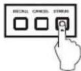
“STATUS” Inquiring status button: To inquire the present status
Example1: To inquire the status of output channel No.7
Operation: Press buttons in the following order "7", "STATUS"
Example2: To inquire the status of all the output channels one by one
Operation: Press the "STATUS" button.
“UNDO” Undo button: To resume to the previous status of the command.
“PROGRAM” Group programming button: To define, recall and clear a group of output channels.
Example 1: To group the output channels No.1, 2,3,4,5 under the Group 1
Operation: Press buttons in the following order “1”, “Program”, “Program”, “1”, “2”, “3”, “4”, “5”
Example 2: To transfer signal from input channel No.1 to Group 2
Operation: Press buttons in the following order “1”, “Program”, “2”
Example 3: To clear the output channels under Group 1
Operation: Press buttons in the following order “1”, “Program”, “0”
Note: Please clear the group to be set before grouping it.
“←” Backspace button: To erase the last input entry that was entered.
“THROUGH” Through button: To transfer signals directly to the corresponding output channels.
Example: To transfer signals from input channels No.1, 2, 3 to their corresponding output channels.
Operation: Press buttons in the following order “1”, “/”, “2”, “/”, “3”, “THROUGH”
“CLOSE” Close button: To switch off the output channels
Example: To switch off the output channels No.1, 2
Operation: Press buttons in the following order "1", "END", "2", "END", "CLOSE"
“LOCK” Lock button: To lock buttons on the front control panel hold it for 3 seconds.
Note: When the control panel is being locked, the switcher still can be controlled via RS232 port. To unlock it, a password is needed.
“DEMO” Demo button: To demonstrate the commands one by one every 3 seconds.
The Switch can be controlled directly by entering the following command:
“Input Channel” + “Switching Mode” + “Output Channel” + “END” + “ENTER”
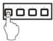


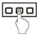
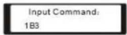
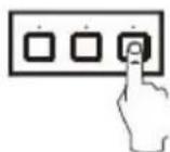


1、Press the button for input channel number "1" Display feedback on LCD: "1"
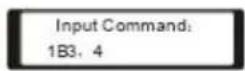
2、Press the button for switching mode "AV" Display feedback on LCD: "B" for the switching mode of video and audio ("A" for the switching mode of audio only; "V" for the switching mode of video only)
3、Press the button for the first output channel number "3" Display feedback on LCD: "3"
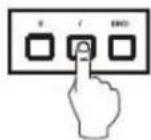
4、Press the break button"/" Display feedback on LCD: ", " for a break between two channels in a command
5、Press the button for the second output channel number "4" Display feedback on LCD: "4"
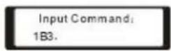
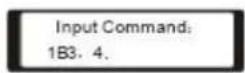
- Press the button "END" to finish the command Display feedback on LCD: "."
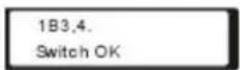
7、Press the button "ENTER" to perform this command Display feedback on LCD: "Switch OK"
Example 2: To inquire the status on the output channel No.4 Operation: Press buttons in this order "4", "STATUS"

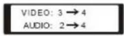
Display feedback on LCD: The video signal of output channel No.4 is transferred from the input channel No.3 and the audio signal is from the input channel No.2
5.5 Remote Control Operation

The Matrix can be controlled with the infrared remote control. The function buttons on the remote are the same as the ones on the front control panel, the remote uses the same commands and in the same order you would input them.
5.6 Operation Of Application Software
Switcher 2.0 is a switcher control application compatible with switchers with different inputs and outputs.
Requirements to run the software
Operating System: Window98/2000/NT/XP
Memory: At least 32mb
Space in hard disk: At least 10M
CD-ROM
COM Port
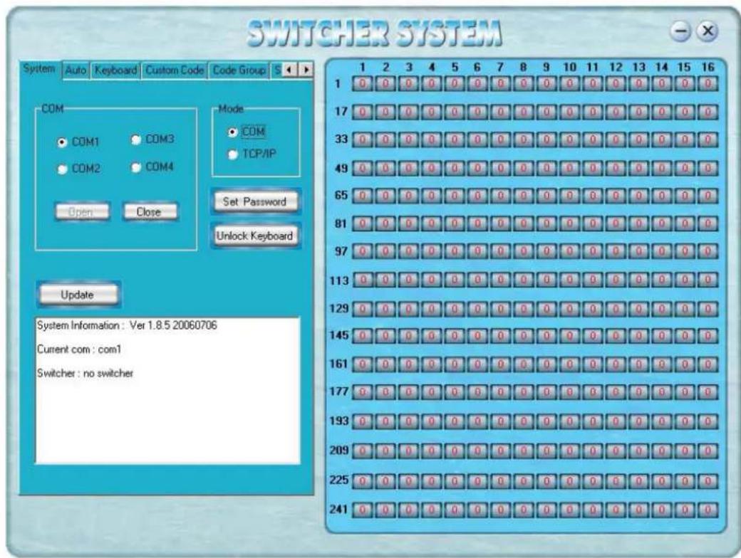
According to practical needs, user can select and operate at different function tabs such as SYSTEM, AUTO, KEYBOARD, CUSTOM CODE, CODE GROUP and SEND/RECEIVE CODE LIST.
On the right hand side of the main window, there are 256 buttons representing for the 256 output channels. When clicking on the button output 1, the text OutPort 1 will appear
“SIGNAL”: Select the switching mode “AV”, “VIDEO” and “AUDIO”
"INPUT A/V PORT": Select an input A/V channel
"INPUT AUDIO PORT": Select an input audio channel\
Once the selections have been entered, click "OK"

"MODE": Select the communication mode between "COM" or "TCP/IP"
"COM": Select a COM port to control the switcher (if selecting "TCP/IP" as the communication mode, a sub-page will appear to input the IP address of the switcher)
“Set Password”: Set the password for the control panel on the Matrix (The password must
be an 8 digit number)
"Unlock Keyboard": Unlock the keyboard of the control panel on the Matrix.

5.7 Keyboard Tab
Because the function buttons on this tab are the same with the ones on the front control panel, it shares the same control operation and command format with the control panel. Please refer the details in Chapter 7 Operation of the Control Panel

5.8 Auto tab
This tab is used to test the switcher after connecting it to all the input and outputs device. For example, to test the function of an DVI32X32 matrix switcher, the Auto Tab is set as below after finishing all the con-nection.
Switch Mode: "AV"
INPUT: From 1 to 32
OUTPUT: From 1 to 32
Delay: 1000ms (1 second)
Click on the button "START" to perform the test, the matrix switcher will:
Transfer the signals from input channel No.1 to output channel No.1-32;
Transfer the signals from input channel No.2 to output channel No.1-32;
Transfer the signals from the input channel No.32 to the output channel No.1-32;
This switching test will perform this way one by one every second until the test is over.

5.9 Cusome Code Tab
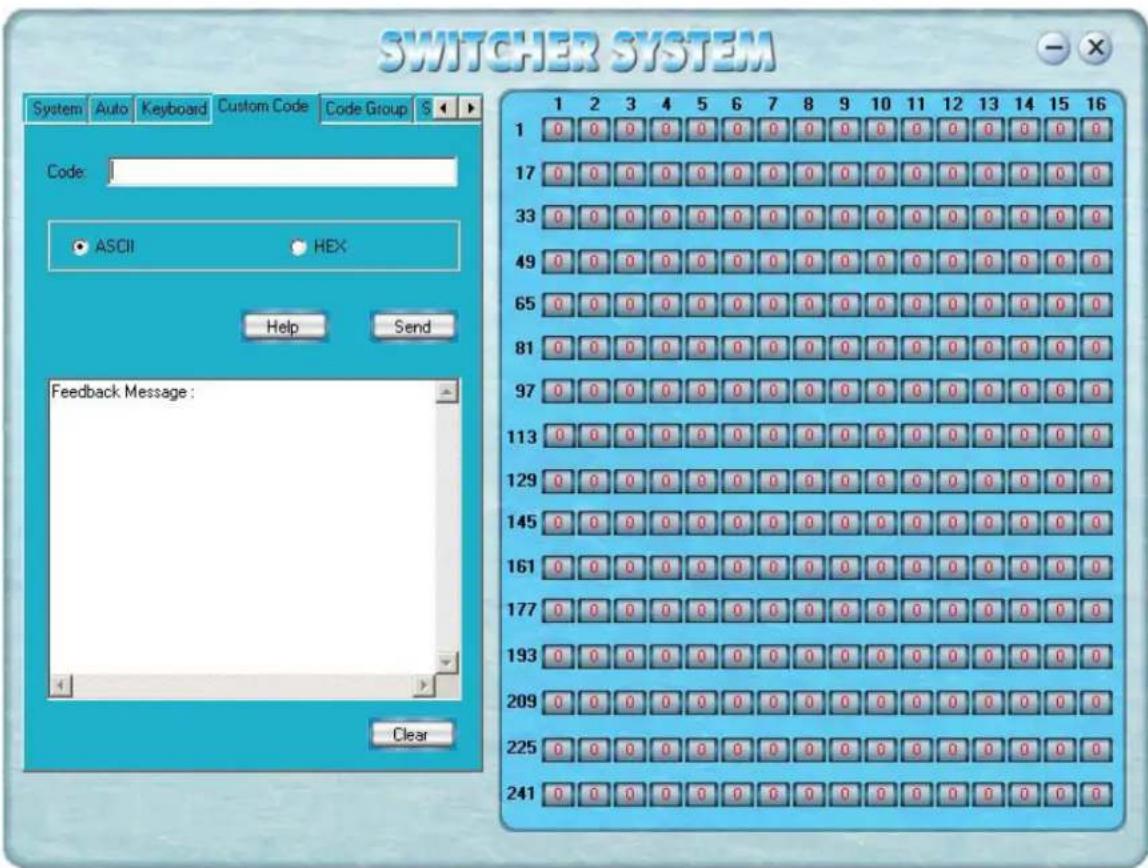
Select between ASCII and HEX format command codes (for command details, please refer to section)
Help: Displays the list of command codes.
Send: Sends out the typed command codes.
For example, to transfer the video and audio signals from the input channel No.1 to the output channel No.7, and the audio signals from the input channel No.2 to the output channel No.4, just perform the following steps below.
- Select the "ASCII" as the command codes format;
- Input the command codes "1B7.2A4." at the blank of Codes;
- Click the button "Send" to perform the commands.
5.10 Code Group Tab
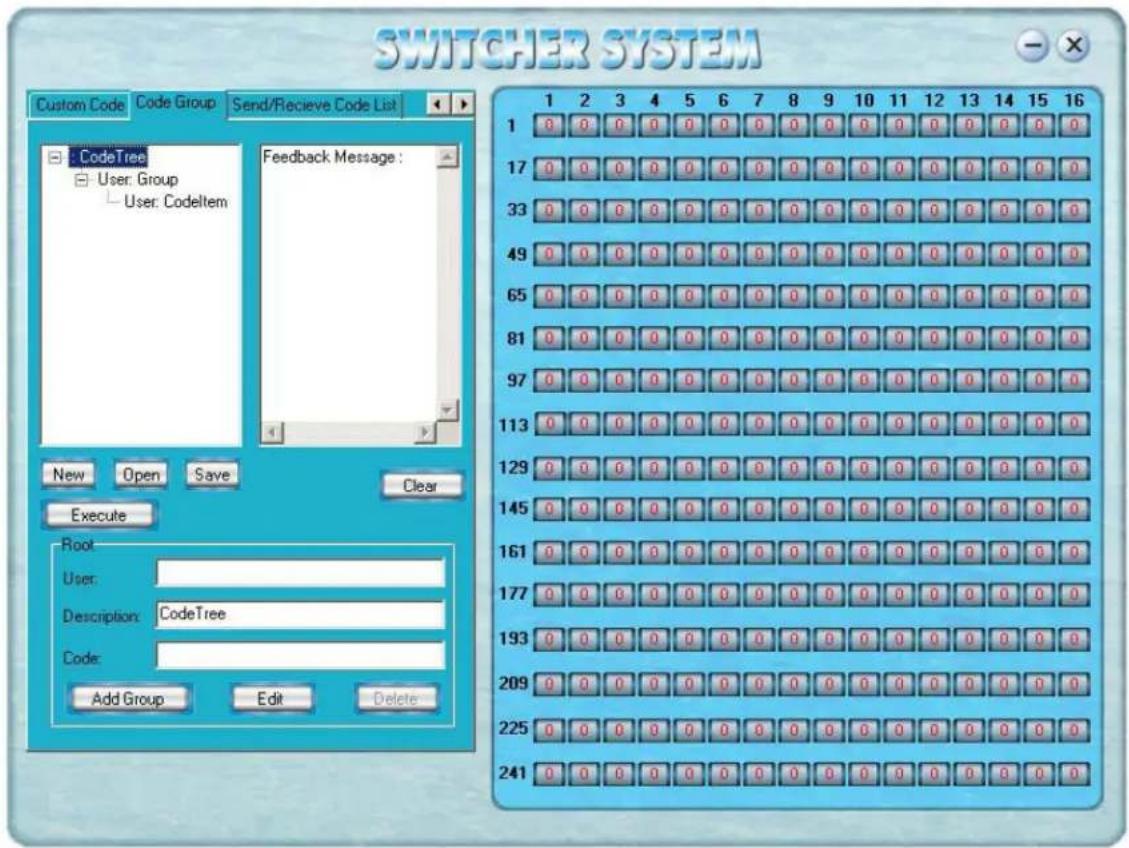
New: Create new a group of preset commands
Open: Opens a group of preset commands
Save: Saves the present group of preset commands
Execute: Executes a selected preset command or a selected group of preset commands
Clear: Clears the feedback window
Add Code Item: To add another new group of preset commands
Edit: To edit the User's name (User),
Delete: Deletes the selected group.
5.11 Send/Receive Code List Tab
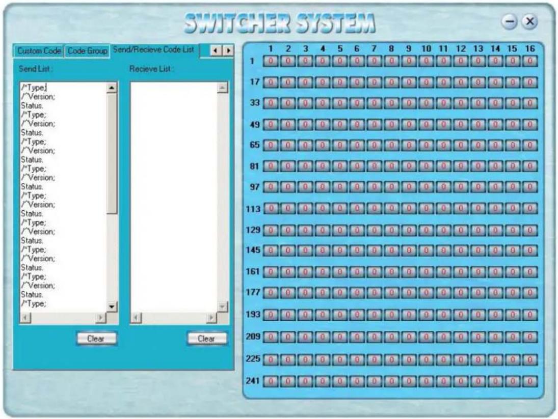
Send List window: Lists sent command code
Received List window: Lists feedback from the switcher
Clear: Clears either of the two lists
6. Operation of RS232
| Command Types Command Codes Functions | |
| System Command | |
| /*Type; Acquires the models information. | |
| /+xxxxxxxx; Rewrites the passwords: must be 8 digits. | |
| /%Lock; Locks the keyboard. | |
| /%Unlock; Unlocks the keyboard. | |
| /:BellOff; Turn off the buzzer. | |
| /:BellOn; Turn on the buzzer. | |
| /^Version; Acquires the version of software | |
| / | |
| [x1]All Transfer signals from input channel [x1] to all output channels |
Operation Command

All#
Transfer all input signals to matching
output channels.
All\$
Switch off all output channels.
[x1]#
Transfer signals from input channel [x1] to output
| Command Types Command | and Codes Functions | |
| [X1]*[X2]Transfer audio | to signals from input channel [x1] to output channel [x2]. | |
| [X1]*[X2]% Transfer video | co signals from input channel [x1] to output channel [x2]. | |
| [X1]*[X2]& Transfer video | co signals from input channel [x1] to output channel [x2]. | |
| Operation Command | ||
| All# Transfer all input signals | to matching output channels. | |
| All Switch off all output channels. | ||
| [x1]# Transfer signals from input channel [x1] to output channel [x1]. | ||
| [x1][x1] . Switch off output channel [x1]. | ||
| [x1] V[x2] Transfer the video signals from input channel [x1] to output channel [x2]. | ||
| [x1] V[x2],[x3],[x4] Transfer the video signals from input channel [x1] to output channels [x2], [x3] and [x4]. | ||
| [x1] A[x2] Transfer the audio signals from input channel [x1] to output channel [x2]. | ||
| [x1] A[x2],[x3],[x4] Transfer the audio signals from input channel [x1] to output channels [x2], [x3] and [x4]. | ||
| [x1] B[x2] Transfer both video and audio signals from input channel [x1] to output channel [x2]. | ||
| [x1] B[x2],[x3],[x4] Transfer both video and audio signals from input channel [x1] to output channels [x2], [x3] and [x4]. | ||
| [x1]P[x2] | Transfer signals from input channel [x1] to all output channels in group [x2]. | |
| [x1]PP[x2],[x3],[x4] | Group output channels [x2], [x3] and [x4] under group [x1]. | |
| S[x] | Acquires the output channels in Group[x]. | |
| Status[x1] | Acquires the input channel to the output channel [x1]. | |
| Status | Acquires the input channel to the output channels one by one. | |
| Save[Y] | Save the present operation to the preset command [Y]. [Y] ranges from 0 to 9. | |
| Recall[Y] | Recall the preset command [Y]. | |
| Clear[Y] | Clear the preset command [Y]. | |
| [X1]*[X2]! | Transfer both video and audio signals from input channel [x1] to output channel [x2]. | |
7. Technical Specifications
| ModeSpecification | DVI0808-A |
| Video | |
| Gain 0 dB | |
| Bandwidth 165MHz, All digital | |
| Max resolution | 1920x1200 |
| Clock Jitter <0.15 Tbit | |
| Rise time <0.3Tbit (20%-80%) | |
| Fall time <0.3Tbit (20%-80%) | |
| Max transfer delay 5nS(±1nS) | |
| Switching speed 200 ns(Longest time) | |
| Signal type DVI-D digital T.M.D.S signal | |
| Video input | |
| Port DVI-D female port | |
| Signal strength | T.M.D.S +/- 0.4Vpp |
| Maximum/Minimum level | T.M.D.S 2.9V/3.3V |
| Resistance 50 Ω | |
| Input EDID | Default EDID |
| Max error in DC offset | 15mV |
| Max distance | Less than 36 meters, 1920x1200 |
| Video output | |
| Port DVI-D female port | |
| Maximum/Minimum level | T.M.D.S 2.9V/3.3V |
| Impedance 50 Ω | |
| Max distance | Less than 7 meters, 1920x1200 |
| Audio signal | |
| I/O port | 5 3.8mm screw connector |
| Gain 0dB | |
| Frequency | 20 Hz ~ 20 kHz, |
| Noise | 0.03% @ 1 kHz (rating voltage) |
| S/N | >90dB |
| Stereo separate | >80dB @ 1 kHz |
| CMRR | >75dB @: 20 Hz ~ 20 kHz |
| Signal type Stereo, balance or unbalance | |
| Resistance | Input: >10 kΩ (balance or unbalance)Output: 50 Ω (unbalance), 100 Ω (balance) |
| ModeSpecification | AT-DVI0808/A | AT-DVI1616/A AT-DVI3232/A | |
| Max input level | +19.5dBu, (balance or unbalance) | ||
| Gain offset ±0.1dB | |||
| Max output level | +19.5dBu, (balance or unbalance) | ||
| Control | |||
| Serial control port RS-232, 9-pin female D | |||
| Baud rate and protocol | Baud rate: 9600 Data bit: 8 Stop bit: 1 Parity bit: none | ||
| Serial control poling protocol | 2 = TX, 3 = RX, 5 = GND | ||
| Connector | RJ-45 Female(Optional accessory) | ||
| Protocol | |||
| Speed Full/half-duplex | 10/100M | ||
| Control application | 《Switch 2.0》 | ||
| Features | |||
| Power supply | 100VAC ~ 240VAC, 50/60 Hz, universal international power supply | ||
| Temperature | Storing and operating temperature: -20° ~ +70°C | ||
| Humidity | Storing and operating humidity: 10% ~ 90% | ||
| Size (mm) | 430(L)X260(W)X133.5 (H) | 266(L)x485(W)x311(H) | 266(L)x485(W)x620(H) |
| weight | 4.2kg | ||
| MTBF | 30,000 hours | ||
| Warranty | 3 Year Warranty | ||
8. Troubleshooting
| Output image is displayed with a ghost Check display | settings, try another high quality cable |
| Color loss or no video on output signal Check both the input and output connections | |
| Remote control doesnt work Check batteries, If borken, contact dealer | |
| The switcher cannot be controlled by computer through COM port. | Check the COM pot in the software.Make sure the COM is working |
| NO sound when switching with I/O signal. Make sure the beeper is switched on. If it is it maybe broken inside, contact dealer | |
| NO image on output signal Check the Input and Output connectors they may belose. Check the connection cord it may be borken.Check the output device and make sure it is connected to the output channel. | |
| Power Indicator doesnt work, no display on LCD no response to any operation. | Check the power cord to see it is connected and not damaged. |
| Interference in the output image Check to see if the unit is well grounded. | |
| Static gets stronger when connecting BNC connectors | The unit is not grounded correctly. Correct issue immediately or damage may be caused to the switch. |
| Beepr makes sound. LCD is displaying normally and there is a returning code. But there isnt any Video or Audio out. | Check connections, and replace if are damaged |
| The swticher cannot be controlled by front panel keys, RS-232 port or remote control | The unit may be broken, contact dealer for repair. |
ATLONA
2151 O'toole Ave, Ste D
San Jose CA 95131
Toll Free: 1-877-536-3976
International: 408-954-8782
FAX: 408-954-8792
Website: www.atlona.com
E-MAIL: info@atlona.com

- Safety Operation Guide:
- Safety Operation Guide
- \*\*\*\*\*\*\*\*\*\*\*\*\*\*\*\*\*\*\*\*\*\*\*\*\*\*\*\*\*\*\*\*\*\*\*\*\*\*\*\*\*\*\*\*\*\*\*\*\*\*\*\*\*\*\*\*\*\*\*\*\*\*\*\*\*\*\*\*\*\*\*\*\*\*\*\*\*\*\*\*\*\*\*\*\*\*\*\*\*\*
- Contents:
- Safety Operation Guide....2
- Introduction:
- About the DVI Matrix Switch
- DVI Matrix Switch Model
- Package Contents
- Installation
- Front and Rear View on the Product
- Operation and Control
- RS232, LAN and 3rd Party Control
- Connecting using Input and Output Terminals
- Connecting and Setting up Audio
- Front Control/ Operation
- Remote Control Operation
- Operation Of Application Software
- Keyboard Tab
- Auto tab
- Cusome Code Tab
- Code Group Tab
- Send/Receive Code List Tab
- Operation of RS232
- Technical Specifications
- Troubleshooting
Brand : Atlona
Model : AT-DVI0808
Category : Video switch