
EKHTSU200AC - Water heater DAIKIN - Free user manual and instructions
Find the device manual for free EKHTSU200AC DAIKIN in PDF.


| Product Type | Heat pump water heater |
| Brand | Daikin |
| Model | EKHTSU200AC |
| Capacity | 200 liters |
| Dimensions (H x W x D) | 1500 x 600 x 600 mm |
| Weight | 100 kg |
| Power Supply | 230 V / 50 Hz |
| Energy Efficiency Class | A+ |
| Heating Element | Heat pump with backup electric heater |
| Max Water Temperature | 65 °C |
| Noise Level | 45 dB(A) |
| Refrigerant | R134a |
| Modes | Eco, Boost, Vacation |
| Control Type | Digital display with touch buttons |
| Installation | Indoor floor-standing |
| Maintenance | Clean air filter every 3 months; check anode annually |
| Safety Features | Overheat protection, frost protection, safety valve |
| Spare Parts | Anode, air filter, thermostat, heating element |
| Warranty | 5 years on tank, 2 years on parts |
| Repairability Index | 8.5/10 |
Frequently Asked Questions - EKHTSU200AC DAIKIN
User questions about EKHTSU200AC DAIKIN
0 question about this device. Answer the ones you know or ask your own.
Ask a new question about this device
Download the instructions for your Water heater in PDF format for free! Find your manual EKHTSU200AC - DAIKIN and take your electronic device back in hand. On this page are published all the documents necessary for the use of your device. EKHTSU200AC by DAIKIN.
USER MANUAL EKHTSU200AC DAIKIN
Domestic hot water tank with UK kit for air to water heat pump system

General information....1
Scope of this manual....1
Model identification ....1
Accessories 2
Accessories supplied with the domestic hot water tank ....2
Accessories supplied with the EKUHWHTA kit for
the domestic hot water tank 2
Optional equipment....2
Overview of the unit....2
Position of flexibles....2
Main components....3
Safety devices....3
Outlook diagram....3
Installation of the EKHTSU domestic hot water tank....4
Installation guidelines....4
Installing and commissioning the domestic hot water tank .....4
Installation of the EKUHWHTA kit on the domestic hot water tank..13
Piping requirements ....13
Installation procedure of the EKUHWHTA kit 14
Maintenance....15
Descaling 15
Draining....15
Troubleshooting 15
General guidelines ....15
General symptoms 15
Disposal requirements....16
Technical specifications....16
Domestic hot water tank specifications ....16

READ THESE INSTRUCTIONS CAREFULLY BEFORE INSTALLATION. KEEP THIS MANUAL IN A HANDY PLACE FOR FUTURE REFERENCE.
PLEASE LEAVE THIS MANUAL WITH THE EKHTSU DOMESTIC HOT WATER TANK AFTER INSTALLATION.
IMPROPER INSTALLATION OR ATTACHMENT OF EQUIPMENT OR ACCESSORIES COULD RESULT IN ELECTRIC SHOCK, SHORT-CIRCUIT, LEAKS, FIRE OR OTHER DAMAGE TO THE EQUIPMENT. BE SURE ONLY TO USE ACCESSORIES MADE BY DAIKIN WHICH ARE SPECIFICALLY DESIGNED FOR USE WITH THE EQUIPMENT AND HAVE THEM INSTALLED BY A PROFESSIONAL.
IF UNSURE OF INSTALLATION PROCEDURES OR USE, ALWAYS CONTACT YOUR DAIKIN DEALER FOR ADVICE AND INFORMATION.
THE UNIT DESCRIBED IN THIS MANUAL IS DESIGNED FOR INDOOR INSTALLATION ONLY AND FOR AMBIENT TEMPERATURES RANGING 5°C\~30°C.
INTRODUCTION
General information
Thank you for purchasing this domestic hot water tank.
The domestic hot water tank must be installed by a licensed technician and be installed in compliance with instructions as of subject in this manual, all current legislation, codes of practice and regulations governing the installation of unvented hot water cylinders in force at the date of installation.
This installation is subject to building regulation approval, notify Local Authority of intention to install.
The EKHTSU domestic hot water tank can be connected to EKHBRD*, EKHVM(RD/YD)*, HXHD*, EKHV(H/X)*, EKHB(H/X)* and E(D/B)(H/L)Q* units. The domestic hot water tank is available in two sizes: approximately 200 and 260 litre. Except for EKHB(H/X)* and E(D/B)(H/L)Q* units, all models can be mounted on top of the indoor unit. For installation of the domestic hot water tank on the floor next to the indoor unit, the dedicated EKFMAHTB connection kit is required.
In case of EKHBRD*AA* indoor unit, the kit EKMKHT1 is required.
In case of EKHB(H/X) and E(D/B)(H/L)Q units, the kit EKFMALTA is required. The domestic hot water tank can not be mounted on top of the indoor unit but needs to be floor mounted next to the unit.

For EKHB(H/X) * and E(D/B)(H/L)Q * units
Compatibility with an EKHTSU domestic hot water tank is only possible from EKHB(H/X)*BB* and E(D/B)(H/L)Q*BB* unit types onwards.
Scope of this manual
This installation manual describes the procedures for installing and connecting the EKHTSU domestic hot water tank together with the EKUHWHTA kit.
Model identification
Domestic hot water tank

ACCESSORIES
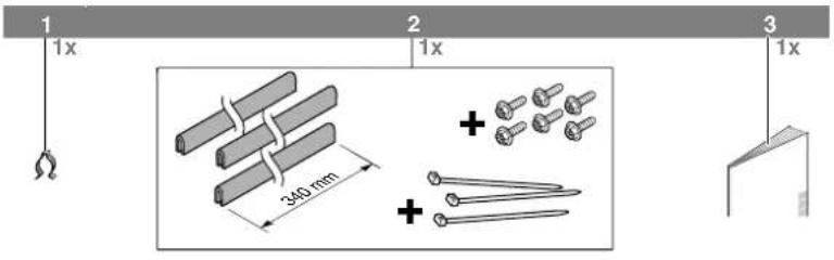
Accessories supplied with the domestic hot water tank
See figure 1.
1 Clamp
2 Knock-out hole assembly (grommet + tie-wraps + screws)
3 Installation manual
4 Unpacking instruction sheet
5 3-way valve assembly (body + motor + clamps) + T-piece
Accessories supplied with the EKUHWHTA kit for the domestic hot water tank
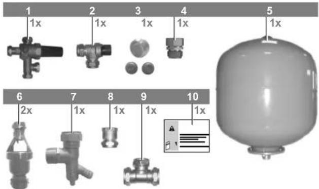
1 Pressure reducing valve
2 Expansion relief valve
3 Blind stop + 2 plastic screw-on closing caps for pressure reducing valve
4 Reducing coupler 22 mm - 15 mm
5 Expansion vessel of 18 litres
6 Tundish
7 Elbow/Drain valve 22 mm x 3/4" Male BSP
8 Adaptor 22 mm x 3/4" Female BSP
9 T-piece 22 mm x 22 mm x 22 mm
10 Instruction sheet
Optional equipment
EKFMAHTB
Connection kit for installation of the domestic hot water tank on the floor next to the indoor unit.
Refer to the installation manual of the kit for more details.
EKFMALTA
In case the EKHTSU*AC domestic hot water tank is to be installed together with a EKHB(H/X)* or a E(D/B)(H/L)Q* series (indoor) unit, the additional EKFMALTA kit is required.
Refer to the installation manual of the kit for more details.
EKMKHT1
In case the EKHTSU*AC domestic hot water tank is to be installed on top of an EKHBRD*AA* series indoor unit, the additional EKMKHT1 kit is required.
Refer to the instruction sheet of the kit for more details.
OVERVIEW OF THE UNIT

The total system (indoor unit and outdoor unit) is designed for combination with a Daikin domestic hot water tank. In case another tank is being used in combination with the Daikin indoor unit, Daikin cannot guarantee neither good operation nor reliability of the system. For those reasons Daikin cannot give warranty of the system in such case.
Position of flexibles (Factory mounted)

natural_image
Close-up of black hoses attached to a metal frame, no visible text or symbols
natural_image
3D rendering of a mechanical component with internal components and mounting holes (no text or symbols visible)Main components
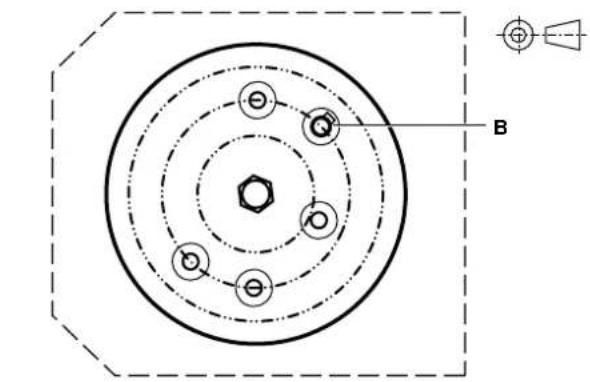
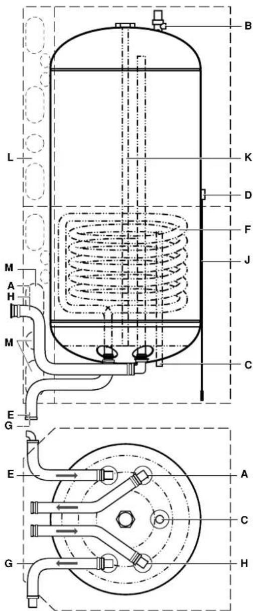
A Hot water from the tank (G 3/4" Female)
B Temperature and pressure relief valve
C Recirculation connection (G 1/2" Male)
D Thermistor socket
E Hot water from the indoor unit to the tank coil (quick coupling 90°)
F Heat exchanger coil
G Return water from the tank coil to the indoor unit (quick coupling)
H Cold water to the tank (G 3/4" Female)
J Thermistor
K Anode
L Casing
M Knock-out holes for water piping
Water flow direction
Safety devices

■ The domestic hot water tank relief valve connections may not be used for other purpose.
This domestic hot water tank can only be used with an EKHBRD*, EKHVM(RD/YD)*, HXHD*, EKHV(H/V)*, EKHB(H/X)* or E(D/B)(H/L)Q* unit.
Compatibility with an EKHTSU domestic hot water tanks is only possible from EKHB(H/X)*BB* and E(D/B)(H/L)Q*BB* unit types onwards.
Thermal protector — The heat pump unit is equipped with a thermal protector. The thermal protector is activated when the temperature becomes too high. When activated, the protector has to be reset on the heat pump unit by pressing it (for access, remove the decoration panels like indicated in the manual of the heat pump unit).

Switch off the power supply before opening the decoration panels of the indoor unit.
■ Temperature and pressure relief valve
The temperature and pressure relief valve prevents excessive water temperature ( >95°C ) and excessive water pressure ( ≥10 bar) in the domestic hot water tank.
■ Expansion relief valve (EKUHWHTA kit)
The pressure relief valve prevents excessive water pressure ( ≥ 8 bar) in the water circuit.
NOTE

Refer to "Installation of the EKUHWHTA kit on the domestic hot water tank" on page 13 for connection of other safety devices in accordance with relevant local and national regulations.
Outlook diagram (See figure 2 and figure 3)
1 Hot water from the tank (G 3/4" Female)
2 Cold water to the tank (G 3/4" Female)
3 Hot water from the indoor unit to the tank coil (quick coupling 90°)
4 Return water from the tank coil to the indoor unit (quick coupling)
5 3-way valve
6 Knock-out holes for water piping
7 Levelling feet
Domestic hot water tank model H1 H2
| EKHTSU200AC | 2010 mm 1935 mm |
| EKHTSU260AC | 2285 mm 2230 mm |
Installation of the EKHTSU domestic hot water tank

■ Installation shall be done by a licensed technician, the choice of materials and installation shall comply with local and national regulations.
■ The equipment is not intended for use in a potentially explosive atmosphere.
■ Domestic hot water quality must be according to EU directive 98/83 EC.
■ For safety reasons, it is not allowed to add any kind of glycol to the water circuit.
■ To avoid stagnation of water, it is important that the storage capacity of the domestic hot water tank meets the daily consumption of domestic hot water.
In cases where during longer periods of time there is no consumption of hot water, the equipment must be flushed with fresh water before usage.
The disinfection function provided on the equipment is specified in the operation manual of the indoor unit.
It is advised to avoid long runs of piping between the domestic hot water tank and the hot water end point (shower, bath, ...) and to avoid dead ends.
The installation must be in compliance with local and national regulations and may require additional hygienic installation measures.
■ For compliance with UK Building Regulations, thermostatic mixing valves must be installed.
Immediately after installation, the domestic hot water tank must be flushed with fresh water. This procedure must be repeated at least once a day the first 5 consecutive days after installation.
If required by relevant local and national regulations, connect a recirculation pump in between the hot water end point and the recirculation connection of the domestic hot water tank.
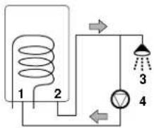
flowchart
graph TD
    A["1 Coil"] --> B["2"]
    B --> C["3"]
    C --> D["4"]
    D --> E["Return Line"]
    style A fill:#f9f,stroke:#333
    style B fill:#ccf,stroke:#333
    style C fill:#cfc,stroke:#333
    style D fill:#fcc,stroke:#333
    style E fill:#ffc,stroke:#333
1 Recirculation connection
2 Hot water connection
3 Shower
4 Recirculation pump
Installation guidelines
Keep in mind the following guidelines when installing the domestic hot water tank:
■ The installation location is frost-free.
■ Standard installation location of the domestic hot water tank is on top of the indoor unit.

If available service space to left and/or right side is limited, carefully consider all indoor module installation steps first.

Not applicable for EKHB(H/X)* and E(D/B)(H/L)Q* units.
The domestic hot water tank can be floor mounted as well. In that case, the dedicated EKFMAHTB connection kit for installation of the domestic hot water tank next to the indoor unit is required and to be ordered separately.
Locate the domestic hot water tank in a suitable position to facilitate ease of maintenance. Refer to the grey-coloured zones indicated in the outlook diagram figure and to the installation manual of the indoor unit.
To avoid back siphonage it is advised to install a non-return valve on the water inlet of the domestic hot water tank in accordance with local and national regulations.
■ Take care that in the event of a leak, water can not cause any damage to the installation space and surroundings.
If installing an EKHTSU + domestic hot water tank, installing the kit EKUHWHTA is obligatory. Refer to the UK Building Regulation G3.
Installing and commissioning the domestic hot water tank
■ Unpack the domestic hot water tank according to the instructions mentioned on the unpacking instruction sheet.
- Check if all domestic hot water tank accessories are enclosed (see "Accessories" on page 2).
Remove the indoor unit casing
For EKHBRD\*, EKHVM(RD/YD)\*, HXHD\* and EKHV(H/V)\* units
Take away the decoration panels by removing the 2 bottom screws and then unhitching the panel.
Mount the top plate of the indoor unit on the domestic hot water tank module.

For EKHB(H/X) * units


Refer to the instruction sheet delivered with the 3-way valve.
1 In case of EKHBRD\*, HXHD\* and EKHVM(RD/YD)\* units
Remove both parts of the drain plate on top of the indoor unit before installing the 3-way valve.
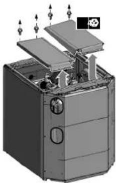
natural_image
3D diagram of a computer tower with visible internal components and directional arrows (no text or symbols)In case of EKHBRD\*, HXHD\* and EKHV(H/X)\* units
Remove the indoor unit switch box by unscrewing fixations and by then sliding the switch box aside without disconnecting any wiring connections.

In case of EKHB(H/X) * and E(D/B)(H/L)Q * units
Go to the step 2.
2 Installation position.
■ For EKHBRD*, EKHVM(RD/YD)*, HXHD*, EKHV(H/X)* units, this 3-way valve must be installed in the indoor unit.

1 From unit
2 To domestic hot water tank
3 To room heating
■ For EKHB(H/X)\* and E(D/B)(H/L)Q\* units

1 From unit
2 To domestic hot water tank
3 To room heating
3 Unpack the 3-way valve body and 3-way valve motor. Verify that following accessories are provided with the motor.

1 Sleeve
2 Valve motor cover
3 Screw
4 Turn knob
4 Put the sleeve on the valve and turn the valve so that the sleeve is positioned according to the figure below.


If the valve is not positioned in this way before mounting the motor, the valve will give way to both domestic water and room heating during operation.
Install the 3-way valve body in the pipework.

Avoid contact between hot piping and electrical wiring at all time.
Refer to the figure below before making the connection.
■ For EKHBRD* units only.

flowchart
graph TD
    A["1: Valve assembly"] --> B["2: Rear assembly"]
    B --> C["3: Rear assembly"]
    C --> D["4: Rear assembly"]
    D --> E["5: Airlock assembly"]
    E --> F["6: Sensor assembly"]
    F --> G["7: Rear assembly"]
    G --> H["8: Rear assembly"]
    H --> I["9: Rear assembly"]
    I --> J["10: Final installation"]

natural_image
Mechanical assembly diagram showing a linkage mechanism and motor components (no text or labels visible)■ For EKHVMRD* and HXHD* units only.


flowchart
graph TD
    A["Component 1"] --> B["Component 2"]
    B --> C["Component 3"]
    C --> D["Component 4"]
    D --> E["Component 5"]
    E --> F["Component 6"]
    F --> G["Component 7"]
    G --> H["Component 8"]
    H --> I["Component 9"]
    I --> J["Component 10"]
    J --> K["Component 11"]
    K --> L["Component 12"]
    style A fill:#f9f,stroke:#333
    style B fill:#ccf,stroke:#333
    style C fill:#cfc,stroke:#333
    style D fill:#fcc,stroke:#333
    style E fill:#cff,stroke:#333
    style F fill:#ffc,stroke:#333
    style G fill:#cfc,stroke:#333
    style H fill:#fcc,stroke:#333
    style I fill:#ffc,stroke:#333
    style J fill:#cfc,stroke:#333
    style K fill:#fcc,stroke:#333
    style L fill:#ffc,stroke:#333
■ For EKHB(H/X)* units only.

flowchart
graph TD
    A["Motor"] --> B["PLC"]
    B --> C["MC"]
    C --> D["Pressure Gauge"]
    D --> E["IP41"]
    E --> F["Control Unit"]
    F --> G["Thermal Relay"]
    G --> H["FCU1 FCU2 FCU3"]
    H --> I["Motor M"]
    I --> J["FHL1 FHL2 FHL3"]
■ For E(D/B)(H/L)Q* units only.

flowchart
graph TD
    A["Air Input"] --> B["Refrigerator Unit"]
    B --> C["FHL1"]
    B --> D["FHL2"]
    B --> E["FHL3"]
    C --> F["Heat Exchanger"]
    D --> F
    E --> F
    F --> G["Condenser"]
    G --> H["FCU1"]
    G --> I["FCU2"]
    G --> J["FCU3"]

The 3-way valve needs to be installed indoors.
6 Push the motor on the sleeve.
Make sure not to rotate the sleeve during this action, so as to maintain the valve position as set during step 4.
7 Put the turn knob on the valve motor cover as shown below.
Room heating Domestic hot water tank

Make sure that the turn knob is completely pushed in to allow the turn knob being operated automatically by the unit. If the turn knob is lifted slightly, manual operation is possible.
8 Perform the wiring in the (indoor) unit switch box in accordance with the following figure: (make sure power supply is switched off)
EKHBRD* / EKHVM(RD/YD)* / HXHD*
X2M X2M
| 3 | 4 | 5 |
| 3-way valve 3-way valve | ||
| BLU | BLK | BRN |
| N | Y | L |
EKHV(H/X)* / EKHB(H/X)* / E(D/B)(H/L)Q*
| 8 | 9 | 1 | |
| BRN | BLU | BLK | |
| L | N | ||
Make sure to follow the appropriate wiring routing inside of the unit (this wiring routing can be found in the installation manual of the indoor unit).
Refer also to the wiring diagram delivered with the indoor unit.
Installing the hot water tank on top of the indoor unit
1 Remove the top front decoration panel of the tank module as indicated in the figure.
2 Routing of the flexible hoses with threaded connection coupling (G 3/4" female).
Depending on the installation location (left or right side installation), punch the required right or left knock-out

natural_image
3D diagram of a computer tower with an open door and directional arrows indicating movement (no text or symbols)holes out of the rear plate. Apply the grommet to the edges of the knocked out holes to protect the flexible hoses.
If the recirculation connection is used, connect a tube with threaded connection to this hole and guide it through a hole in the rear plate too.
3 Mount the tank module on top of the indoor unit.

Not applicable for EKHB(H/X)* and E(D/B)(H/L)Q* units.

Because of the weight of the domestic hot water tank, it is advised to handle and lift it with two persons.
■ Refer to the figure below and make sure that the positioning guides on all four corners of the domestic hot water tank bottom perfectly match on the positioning guides of the indoor unit top when mounting the tank module.

natural_image
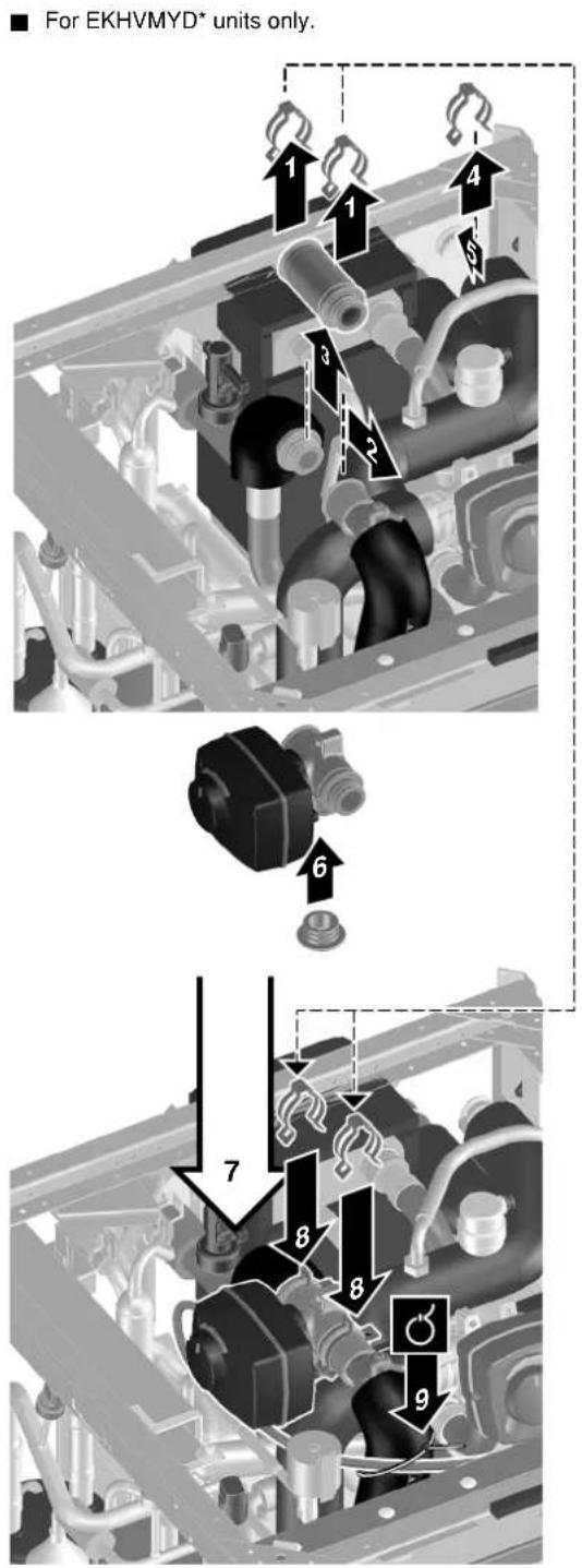
Diagram showing a mechanical assembly with three views of a device, including a close-up view of internal components (no text or symbols present)4 Connect the flexible hoses as indicated below and in figure 4, figure 5, figure 6 and figure 7.
1 Hot water from the tank (G 3/4" Female)
2 Cold water to the tank (G 3/4" Female)
3 Recirculation connection (G 1/2" Male)
4 Hot water from the indoor unit to the tank coil (quick coupling 90°)
5 Return water from the tank coil to the indoor unit (quick coupling)
6 3-way valve

Water flow direction
■ For EKHBRD* units

■ For EKHVMRD* and HXHD* units

natural_image
Mechanical diagram showing pipe connections and valve positions (no text or labels)■ For EKHVMYD* units

■ For EKHV(H/X)* units

natural_image
Technical diagram of a mechanical piping system with no visible text or symbols■ For EKHB(H/X) and E(D/B)(H/L)Q units only

flowchart
graph TD
    A["Heat Exchanger H/X"] --> B["Water Heater"]
    B --> C["Heat Exchanger H/X"]
    C --> D["Water Heater"]
    D --> E["Heat Exchanger H/X"]
    style A fill:#f9f,stroke:#333
    style B fill:#ccf,stroke:#333
    style C fill:#cfc,stroke:#333
    style D fill:#fcc,stroke:#333
    style E fill:#ffc,stroke:#333

It is recommended to install a shut off valve to the cold water inlet. Close this shut off valve during periods of absence to avoid damage to the surroundings in case water should leak.
5 Fix the side bottom decoration panels of the domestic hot water tank to the indoor unit.

Not applicable for EKHB(H/X)* and E(D/B)(H/L)Q* units.

1 Decoration panel
2 Quick fixation hole
3 Fasten with 2 screws
6 Connect the pressure relief valve (field supply, opening pressure maximum 10 bar) and the drain.
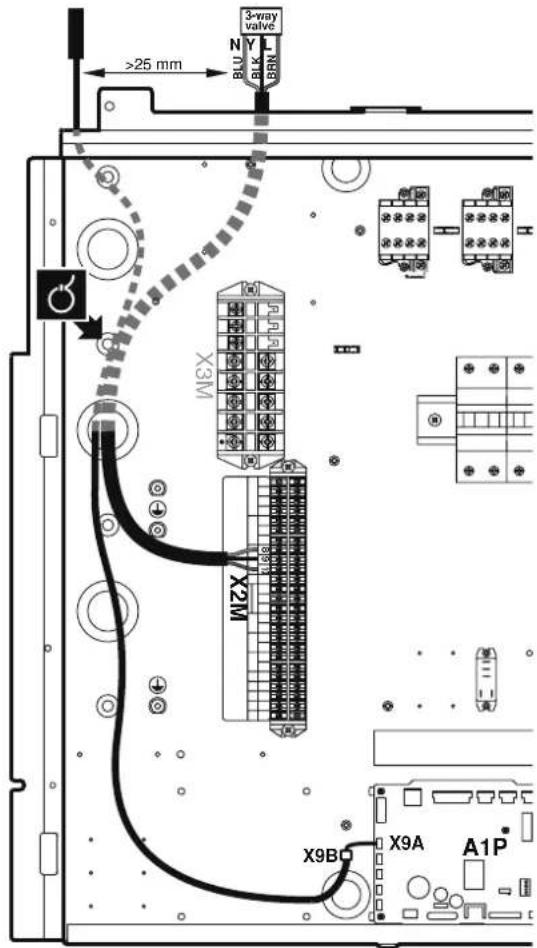
7 Connect the thermistor wire to the indoor unit switch box. Make sure power supply is switched off. Refer to the wiring diagram delivered with the indoor unit.
■ For EKHBRD*, EKHVM(RD/YD)* and HXHD* units only

natural_image
Interior view of a mechanical assembly with a curved pipe and mounting holes (no visible text or symbols)■ For EKHV(H/X)* units only

natural_image
Interior view of a mechanical or electrical enclosure with labeled components and directional arrows (no readable text or symbols)The distance between the thermistor cable and power supply cable must always be at least 25 mm to prevent electromagnetic interference on the thermistor cable.
1 Plug the thermistor cable connector in the socket X11A (EKHBRD*, EKHVM(RD/YD)* and HXHD* (A3P)) or X9A (EKHV(H/X)* (A1P)) on the PCB.
2 Fix the cables to the cable tie mountings with cable ties to ensure strain relief.
3 When routing out cables, make sure that these do not obstruct mounting of the indoor unit cover.
Note: only relevant field wiring is shown.
■ For EKHBRD* indoor units only.

■ For EKHVM(RD/YD)* and HXHD* indoor units only.

■ For EKHV(H/X) * indoor units only.

■ For EKHB(H/X)* indoor units only
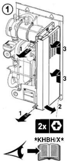

■ For the E(D/B)(H/L)Q* units
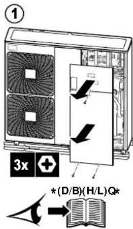

8 Only for EKHBRD*, EKHVM(RD/YD)* and HXHD* units: reattach the drain plate on the indoor unit.

Not applicable for EKHB(H/X)* and E(D/B)(H/L)Q* units.
9 Commissioning

The domestic hot water tank coil must be filled with water at the indoor unit water inlet. This to avoid that dirt enters the system.
Follow the next steps to fill up the tank:
1 Open each hot water tap in turn to expel air from the system pipe work.
2 Open the cold water supply valve. Make sure the decoration panels of both the domestic hot water tank and the indoor unit are aligned.
3 Close all water taps after all air is expelled.
4 Check for leaks.
5 Manually operate the temperature and pressure relief valve to ensure free water flow through the discharge pipe (turn knob counterclockwise). Refer to "Main components" on page 3 for location of the temperature and pressure relief valve.
10 Reattach the temperature and pressure relief valve insulation piece, and both front decoration panels of the domestic hot water tank.
11 Reattach the front decoration panel of the indoor unit.
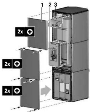
1 Decoration panel
2 Insulation piece
3 Temperature and pressure relief valve insulation piece

Not applicable for EKHB(H/X)* and E(D/B)(H/L)Q* units.
Refer to the installation manual of the heating unit.
Installing the hot water tank by the side of the indoor unit
Refer to the manual delivered with the kit EKFMAHTB.
Connecting to the domestic hot water tank recirculation connection
When loosening the recirculation plug or when connecting piping to the recirculation connection, always use 2 whrenches together.


All pipework and fittings must be flushed free of all flux and debris prior to the fitting of controls of this kit. Failure to do this may cause irreparable damage to the controls.
All cautions as under chapter "Installation of the EKHTSU domestic hot water tank" on page 4 remain of extreme importance and are equally valid in this chapter.

Piping requirements
■ Tundish
Install the tundishes in a vertical position within a maximum of 500 mm away from the temperature and pressure relief valve on the domestic hot water tank and the expansion relief valve included in the EKUHWHTA kit.
■ Tundish pipework
Tundish pipework must be 22 mm metal pipe with a minimum vertical length of 300 mm below the tundish. Maximum permitted (equivalent) length of 22 mm pipework is 9 m. Each bend or elbow is equivalent to 0.8 m of pipework. All pipework must have a continuous fall.
Sizing of copper discharge pipe D2 for common temperature relief valve outlet sizes
| Valve outlet size | Discharge pipe size D1 | Discharge pipe size D2 from tundish | Maximum resistance allowed, expressed as a length of straight pipe (i.e. no elbows or bends) | Resistance created by each elbow or bend |
| 15 mm | 15 mm | 22 mm up to 9 m | 0.8 m |
■ Requirements to discharges
■ Discharge piping, tundish, drain valves, etc. must be positioned away from any electrical components.
The discharge pipe away from the tundish must terminate in a safe, visible position without forming any risk to persons in the vicinity.
NOTE

To access the tundish connected to the temperature and pressure relief valve, the front decoration panels need to be removed.
If in any doubt, refer to Building Regulation G3.

Do not install any valves between the domestic hot water tank and relief valves/expansion vessel.
Installation procedure of the EKUHWHTA kit
1 Locate the domestic hot water tank in a suitable position to facilitate the installation of water supply, discharge fittings and pipework. It is therefore recommended to first read through this whole procedure.
Refer to the figure on the facing page at the start of this chapter for full understanding of next procedure steps.
Pre-assembly
2 Pre-assemble the pressure reducing valve (part 1 of this kit, refer to page 2) by mounting the blind stop and the 2 black plastic screw-on closing caps (part 3 of this kit), so that the pressure reducing valve is ready for ins

natural_image
Mechanical component diagram showing a lever mechanism with multiple spheres and directional arrows (no text or labels)The black plastic plugs in the pressure reducing valve body are pressure gauge connections to enable pressure monitoring to be carried out, should the system develop a fault. It is recommended that these be accessible (the pressure reducing valve has two - only one need be accessible).
3 Mount the reducing coupler (part 4 of this kit) in between the pressure reducing valve and the expansion relief valve (part 2 of this kit) using a length of copper tube ∅22 mm (to the pressure reducing valve) and a length of copper tube ∅15 mm (to the expansion relief valve).

4 Pre-assemble the adaptor and expansion vessel (parts 8 and 5 of this kit) so that the expansion vessel is ready for installation.
5 Remove the insulation piece to get access to the factory fitted temperature and pressure relief valve. Manually operate the temperature and pressure relief valve to ensure free water flow through discharge pipe. Turn knob left.
Water main in
6 Fit the elbow/drain valve (part 7 of this kit) in the cold water flexible hose coming out of the rear plate.
Pay attention to position the drain valve in such a way that 80% of the domestic hot water tank can be drained.
7 Position both, the pressure reducing valve with integrated non return valve and line strainer and the expansion relief valve (parts 1 and 2 of this kit - see also procedure step 2) as high as possible and connect it to the water mains inlet.
The expansion relief valve must be installed with a horizontal discharge. If fitted inverted, debris may be deposited on the seat and cause fouling of the seat when the valve operates. Check direction of flow arrows.
Fit a length of copper tube ∅22 mm (field supply) in between the elbow/drain valve (procedure step 6) and the pressure reducing valve.
Make sure to provide for a connection on this pipe to the expansion vessel (part 5 of this kit).
8 Fit a length of copper tube ∅22 mm (field supply) in between the T-piece (part 9 of this kit) and the pre-assembled expansion vessel (procedure steps 4 and 7).
Discharge
9 Remove the front decoration panels of the domestic hot water tank. Install the first tundish (part 6 of this kit) in a vertical position within a maximum of 500 mm away from the temperature and pressure relief valve. Use the foreseen space inside the domestic hot water tank module as indicated in the figure. Use tie-wraps to firmly fix the tundish.
10 Connect a metal discharge pipe ∅15 mm (field supply) from the temperature and pressure relief valve to the tundish (≤500 mm).
11 Install the second tundish (part 6 of this kit) in a vertical position within a maximum of 500 mm away from the expansion relief valve.
12 Connect a metal discharge pipe ∅15 mm (field supply) from the expansion relief valve to the tundish (≤500 mm).
13 Connect discharge pipes from both tundishes. Refer to paragraph "Tundish pipework" on page 13.
All pipework must have a continuous fall and be fitted conform to the requirements of the Building Regulation G3.
After completing the installation
14 After completing the installation, the installer has to fill in the warning label on the tank with indelible ink. The warning label is located on the lower front decoration panel inside.
WARNING
Do not remove
Contact the installer
■ Should the system develop a fault, switch
contact the installer
WARNING TO INSTALLER
■ This installation is subject to building regulation approval.
notify Local Authority of intention to install
■ Use only manufacturer's recommended spare parts.
Contact your local Daikin dealer.
■ Installed by
name
address
tel. No
completion date
TECHNICAL SPECIFICATIONS

MAINTENANCE
In order to ensure optimal availability of the unit, a number of checks and inspections on the unit and the field wiring have to be carried out at regular intervals.

■ Each inspection has to be carried out by a licensed technician and not by the user.
■ Before carrying out any maintenance or repair activity, always switch off the circuit breaker on the supply panel, remove the fuses or open the protection devices of the unit.
■ Make sure that before starting any maintenance or repair activity, also the power supply to the outdoor unit is switched off.
NOTE

The flexible hoses are designed for a 13 year lifetime. It is advised to replace them after this period.
The described checks must be executed at least once a year by a licensed technician.
1 Checking for leaks
To be able to check for leaks, first remove the front decoration panel of the indoor unit and then the front panels of the tank module.
2 Temperature and pressure relief valve
Check for correct operation of the temperature and pressure relief valve. Remove the front decoration panels and insulation piece. Manually operate the temperature and pressure relief valve to ensure free water flow through the discharge pipe. Turn knob left.
3 Pressure reducing valve with integrated non return valve and line strainer
Depending on local water conditions, annual inspection of the integral line strainer, pressure reducing valve cartridge and seating may be necessary.
- Unscrew the retaining nut of the valve. The complete operating mechanism, including the strainer can be removed.
- Clean the filter mesh and cartridge under running water.
- Replace the cartridge, ensuring that the strainer is correctly located and reassemble the unit.
4 Expansion relief valve
Check for correct operation of the expansion relief valve. Manually operate the expansion relief valve to ensure free water flow through discharge pipe. Turn knob left.
Depending on local water conditions, annual inspection of the expansion relief valve cartridge and seating may be necessary.
- Unscrew the expansion relief headwork from valve body.
- Clean valve seat face and seating - do not scratch or damage either seat face or seating.
- Refit in reverse order. Do not over tighten.
Descaling
Depending on the water quality and set temperature, scale can deposit on the heat exchanger inside the domestic hot water tank and can restrict heat transfer. For this reason, descaling of the heat exchanger may be required at certain intervals.

When using means for descaling, it must be ensured that the water quality remains compliant with the requirements of EU directive 98/83/EC.
Draining
Follow the next steps to drain the tank:
1 Switch off the power supply.
2 Turn off the cold water supply valve.
3 Open the hot water taps.
4 Open the drain valve.
TROUBLESHOOTING
This section provides useful information for diagnosing and correcting certain troubles which may occur in the unit.
General guidelines
Before starting the trouble shooting procedure, carry out a thorough visual inspection of the unit and look for obvious defects such as loose connections or defective wiring.

When carrying out an inspection on the supply panel or on the switch box of the unit, always make sure that the circuit breaker of the unit is switched off.
When a safety device was activated, stop the unit and find out why the safety device was activated before resetting it. Under no circumstances safety devices may be bridged or changed to a value other than the factory setting. If the cause of the problem cannot be found, call your local Daikin dealer.
General symptoms
Symptom 1: No water flow from hot taps
| POSSIBLE CAUSES | CORRECTIVE ACTION |
| The main water supply is off. Check that all shut off valves of the water circuit are completely open. | |
| The strainer is blocked. Turn off the water supply, remove and clean the strainer (see "Pressure reducing valve with integrated non return valve and line strainer" on page 15 on how to do this). | |
| The cold water inlet pressure reducing valve is not fitted properly. | Check and refit as required (see "Pressure reducing valve with integrated non return valve and line strainer" on page 15 on how to do this). |
Symptom 2: Water from hot taps is cold
| POSSIBLE CAUSES | CORRECTIVE ACTION |
| The thermal cut-out located in the indoor unit has operated | Check and find the cause of tripping and then reset button.Check if thermistor is correctly installed in thermistor socket.Procedure: remove front panel and insulation, replace or fix the sensor. |
| The indoor unit (EKHBRD*) is not operating. | Check the indoor unit operation.Refer to the manual delivered with the unit.If any faults are suspected, contact your local dealer. |
Symptom 3: Intermittent water discharge
| POSSIBLE CAUSES | CORRECTIVE ACTION |
| Thermal control failure (water will be hot). | Contact your local dealer. |
| The expansion vessel is broken. Replace the expansion vessel. | |
Symptom 4: Continuous water discharge
| POSSIBLE CAUSES | CORRECTIVE ACTION |
| Cold water inlet pressure. Check the pressure reducing valve. Replace the pressure reducing valve if the measured pressure is >2.1 bar. | |
| Temperature and pressure relief valve. | Check and reset button. |
| The expansion relief valve is not functioning properly. | Check for correct operation of the pressure relief valve by turning the red knob on the valve counter clockwise:If you do not hear a clacking sound, contact your local dealer.In case the water keeps running out of the unit, close both the water inlet and outlet shut-off valves first and then contact your local dealer. |
Symptom 5: Dirty water
| POSSIBLE CAUSES | CORRECTIVE ACTION |
| Dirty water Flush or clean the domestic hot water tank after periods of standstill. It could occur that particles in the water deposit on the bottom of the tank. If this deposit layer becomes thick enough it could enter the hot water outlet and contaminate the hot water. | |
| The water has a smell of rotten eggs. Check if this phenomena also occurs with the cold water. If it does, this indicates that there is a problem with the water supply or with the water in the piping, but not with the domestic hot water tank itself.Contact your water supplier.If the problem is not solved, increase the domestic hot water tank temperature above 65°C.If this action solves the problem, the smell is most probably caused by bacterial contamination. Contact your water supplier.If the problem is not solved, contact your local dealer. | |
DISPOSAL REQUIREMENTS
Dismantling of the unit and treatment of parts must be done in accordance with relevant local and national legislation.
TECHNICAL SPECIFICATIONS
Domestic hot water tank specifications
| EKHTSU200AC EKHTSU260AC | ||
| Storage capacity | (I) | 200 260 |
| Internal heat exchanger volume | (I) | 7.5 7.5 |
| Material Stainless steel | ||
| Overall dimensions (h x l x w) | (mm) | 1335 x 600 x 695 1610 x 600 x 695 |
| Operating pressure | (bar) | 2.1 2.1 |
| Maximum primary working pressure (heating side) | (bar) | 3 3 |
| Expansion vessel pre-charge pressure | (bar) | 2.5 2.5 |
| Preset opening pressure of expansion relief valve | (bar) | 8 8 |
| Preset opening temperature of temperature and pressure relief valve | (°C) | 90~95 90~95 |
| Set opening pressure of temperature and pressure relief valve | (bar) | 10 10 |
| Connections Quick coupling/ G3/4" F | ||
| Inspection access type | G1/2" M Recirculation connection | |
| EKHTSU200AC EKHTSU260AC | ||
| Weight | ||
| - empty | (kg) | 70 78 |
| - when full | (kg) | 265 330 |
| Mounting On top of unit or floor mounted | ||
| Maximum water supply pressure | (bar) | 8 8 |
| Maximum temperature domestic hot water | ||
| - EKHBRD* | (°C) | 75 75 |
| - EKHVM(RD/YD)* | (°C) | 75 75 |
| - EKHV(H/X)* | (°C) | 60 60 |
| - HXHD125* | (°C) | 75 75 |
| - EKHB(H/X)* | (°C) | 60 60 |
| - E(D/B)(H/L)Q* | (°C) | 60 60 |
| Maximum temperature heat exchanger | ||
| - EKHBRD* | (°C) | 85 85 |
| - EKHVM(RD/YD)* | (°C) | 85 85 |
| - EKHV(H/X)* | (°C) | 65 65 |
| - HXHD125* | (°C) | 85 85 |
| - EKHB(H/X)* | (°C) | 65 65 |
| - E(D/B)(H/L)Q* | (°C) | 65 65 |
| Supply temperature time(a) | ||
| - EKHBRD011* | (min) | 60 70 |
| - EKHBRD014* | (min) | 50 60 |
| - EKHBRD016* | (min) | 40 50 |
| - EKHVM(RD/YD)50* | (min) | 109 141 |
| - EKHVM(RD/YD)80* | (min) | 68 88 |
| - HXHD125* | (min) | 68 88 |
| - ER(H/L)Q006BA(b) | (min) | 120 153 |
| - ER(H/L)Q007BA(b) | (min) | 110 141 |
| - ER(H/L)Q008BA(b) | (min) | 105 134 |
| - ER(H/L)Q011BA(c) | (min) | 100 129 |
| - ER(H/L)Q014BA(c) | (min) | 93 119 |
| - ER(H/L)Q016BA(c) | (min) | 84 108 |
| - E(D/B)(H/L)Q011* | (min) | 100 129 |
| - E(D/B)(H/L)Q014* | (min) | 93 119 |
| - E(D/B)(H/L)Q016* | (min) | 84 108 |
| Re-heat time(d) | ||
| - EKHBRD011* | (min) | 50 60 |
| - EKHBRD014* | (min) | 40 50 |
| - EKHBRD016* | (min) | 30 40 |
| - EKHVM(RD/YD)50* | (min) | 77 99 |
| - EKHVM(RD/YD)80* | (min) | 48 62 |
| - HXHD125* | (min) | 48 62 |
| - ER(H/L)Q006BA(b) | (min) | 90 115 |
| - ER(H/L)Q007BA(b) | (min) | 83 106 |
| - ER(H/L)Q008BA(b) | (min) | 79 101 |
| - ER(H/L)Q011BA(c) | (min) | 68 88 |
| - ER(H/L)Q014BA(c) | (min) | 66 85 |
| - ER(H/L)Q016BA(c) | (min) | 60 77 |
| - E(D/B)(H/L)Q011* | (min) | 68 88 |
| - E(D/B)(H/L)Q014* | (min) | 66 85 |
| - E(D/B)(H/L)Q016* | (min) | 60 77 |
(a) The time it takes to increase the temperature from 15°C to 60°C
(b) In combination with EKHV(H/X)008* or EKHB(H/X)008*
(c) In combination with EKHV(H/X)016* or EKHB(H/X)016*
(d) The time it takes to increase 70% of the contents of the vessel back up to 60°C

natural_image
Blank grid paper with no text, numbers, or symbols

natural_image
Blank grid paper with no text, numbers, or symbols

natural_image
Blank grid paper with no text, numbers, or symbols
4 EKHBRD*

5 EKHVH/X*

6 EKHVMRD* + HXHD*

- Domestic hot water tank with UK kit for air to water heat pump system
- INTRODUCTION
- General information
- This installation is subject to building regulation approval, notify Local Authority of intention to install.
- For EKHB(H/X) * and E(D/B)(H/L)Q * units
- Scope of this manual
- Model identification
- ACCESSORIES
- Accessories supplied with the domestic hot water tank
- Accessories supplied with the EKUHWHTA kit for the domestic hot water tank
- Optional equipment
- OVERVIEW OF THE UNIT
- Position of flexibles (Factory mounted)
- Safety devices
- Outlook diagram (See figure 2 and figure 3)
- Installation of the EKHTSU domestic hot water tank
- Installation guidelines
- Installing and commissioning the domestic hot water tank
- Remove the indoor unit casing
- For EKHBRD\*, EKHVM(RD/YD)\*, HXHD\* and EKHV(H/V)\* units
- In case of EKHBRD\*, HXHD\* and EKHVM(RD/YD)\* units
- In case of EKHBRD\*, HXHD\* and EKHV(H/X)\* units
- In case of EKHB(H/X) * and E(D/B)(H/L)Q * units
- Installation position.
- ■ For EKHB(H/X)\* and E(D/B)(H/L)Q\* units
- Installing the hot water tank on top of the indoor unit
- Commissioning
- Piping requirements
- ■ Tundish
- ■ Tundish pipework
- ■ Requirements to discharges
- Installation procedure of the EKUHWHTA kit
- Pre-assembly
- Water main in
- Discharge
- After completing the installation
- WARNING
- WARNING TO INSTALLER
- TECHNICAL SPECIFICATIONS
- MAINTENANCE
- Descaling
- Draining
- TROUBLESHOOTING
- General guidelines
- General symptoms
- DISPOSAL REQUIREMENTS
Brand : DAIKIN
Model : EKHTSU200AC
Category : Water heater