
EKSOLHTBV1 - Water heater DAIKIN - Free user manual and instructions
Find the device manual for free EKSOLHTBV1 DAIKIN in PDF.

| Product Type | Solar Kit for Air-to-Water Heat Pump System |
| Model | EKSOLHTBV1 |
| Compatible Indoor Units | Daikin EKHV(H/X) series |
| Compatible DHW Tanks | Daikin EKHTS series |
| Max Operating Pressure (Solar Side) | 6 bar |
| Max Operating Pressure (Unit & Tank Side) | 4 bar |
| Ambient Temperature Range (Installation) | 0°C to 35°C |
| Fluid Temperature Range (Solar Side) | 1°C to 110°C |
| Heat Transfer Fluid | Propylene glycol (non-toxic) |
| Safety Features | DHW tank thermal cut-out, piping thermal cut-out |
| Installation Type | Indoor, frost-free space |
| Required Accessories Included | Installation manual, wiring diagram sticker, thermal cut-outs, sensor holder, connectors, grommet, T-pieces, wire harnesses, EKRP1HB address card, piping clamps |
| Field Wiring Requirements | Connections to solar pump station controller, indoor unit, DHW tank, and solar pump station |
| Error Codes | RR (DHW tank thermal protector open) |
| Disposal | Do not mix with household waste; recycle at specialized facility |
Frequently Asked Questions - EKSOLHTBV1 DAIKIN
User questions about EKSOLHTBV1 DAIKIN
0 question about this device. Answer the ones you know or ask your own.
Ask a new question about this device
Download the instructions for your Water heater in PDF format for free! Find your manual EKSOLHTBV1 - DAIKIN and take your electronic device back in hand. On this page are published all the documents necessary for the use of your device. EKSOLHTBV1 by DAIKIN.
USER MANUAL EKSOLHTBV1 DAIKIN
INSTALLATION AND OPERATION MANUAL
Solar kit for air to water heat pump system
CONTENTS Page
- Definitions.... 1
1.1. Meaning of warnings and symbols.... 1
1.2. Meaning of used terms ...... 2
-
General safety precautions.... 2
-
Introduction.... 3
3.1. General information.... 3
3.2. Scope of this manual 3
3.3. Model identification 3
-
Accessories 3
-
Overview of the solar kit 4
5.1.Main components....4
5.2. Safety functions.... 4
Domestic hot water tank tank thermal cut out.... 4
Piping thermal cut out 4
- General system setup and operation.... 4
- Installation of the solar kit 5
7.1. Selecting an installation location.... 5
7.2. Dimensions and service space 5
7.3. Inspecting, handling and unpacking the unit.... 5
7.4. Installation guidelines.... 5
7.5. Installing the solar kit 5
Procedure 5
Charging water....7
7.6. Field wiring....7
Overview 7
Installing the EKRP1HB in the unit 8
Connecting the temperature sensors....8
Connecting the solar pump station controller, solar pump
station, indoor unit, domestic hot water tank and solar kit ...... 8
- Installation of solenoid valve kit EKUHT2WB 10
8.1. Last steps of mounting the kit inside the unit 10
8.2. Guiding the wiring towards the switch box 10
8.3. Last step of connecting the wiring.... 10
- Start up.... 11
9.1. Commissioning the system before initial start up.... 11
9.2. Checklist for proper functioning.... 11
- Operating instructions.... 11
10.1. Configuring your system 11
Use of schedule timers 11
Setting of domestic hot water tank temperature.... 12
Setting of the solar priority parameter.... 12
- Troubleshooting and servicing 13
11.1. General guidelines.... 13
11.2. General symptoms.... 13
11.3. Error codes 13
-
Disposal requirements.... 13
-
Technical specifications 13
Annex 14
Decision flow of heating the domestic
water by heat pump or by solar kit 14
The English text is the original instruction. Other languages are translations of the original instructions.

CAREFULLY READ THESE INSTRUCTIONS BEFORE INSTALLATION. THEY WILL TELL YOU HOW TO INSTALL, HOW TO CONFIGURE AND HOW TO USE THE EKSOLHTB SOLAR KIT PROPERLY.
KEEP THIS MANUAL IN A HANDY PLACE FOR FUTURE REFERENCE.
THE UNIT DESCRIBED IN THIS MANUAL IS DESIGNED FOR INDOOR INSTALLATION ONLY AND FOR AMBIENT TEMPERATURES RANGING 0°C\~35°C.
1. DEFINITIONS
1.1. Meaning of warnings and symbols
Warnings in this manual are classified according to their severity and probability of occurrence.

DANGER
Indicates an imminently hazardous situation which, if not avoided, will result in death or serious injury.

WARNING
Indicates a potentially hazardous situation which, if not avoided, could result in death or serious injury.

CAUTION
Indicates a potentially hazardous situation which, if not avoided, may result in minor or moderate injury. It may also be used to alert against unsafe practices.

NOTICE
Indicates situations that may result in equipment or property-damage accidents only.

INFORMATION
This symbol identifies useful tips or additional information.
Some types of danger are represented by special symbols:

Electric current.

Danger of burning and scalding.
1.2. Meaning of used terms
Installation manual:
Instruction manual specified for a certain product or application, explaining how to install, configure and maintain it.
Operation manual:
Instruction manual specified for a certain product or application, explaining how to operate it.
Maintenance instructions:
Instruction manual specified for a certain product or application, which explains (if relevant) how to install, configure, operate and/or maintain the product or application.
Dealer:
Sales distributor for products as per the subject of this manual.
Installer:
Technical skilled person who is qualified to install products as per the subject of this manual.
User:
Person who is owner of the product and/or operates the product.
Service company:
Qualified company which can perform or coordinate the required service to the unit.
Applicable legislation:
All international, European, national and local directives, laws, regulations and/or codes which are relevant and applicable for a certain product or domain.
Accessories:
Equipment which is delivered with the unit and which needs to be installed according to instructions in the documentation.
Optional equipment:
Equipment which can optionally be combined to the products as per the subject of this manual.
Field supply:
Equipment which needs to be installed according to instructions in this manual, but which are not supplied by Daikin.
2. GENERAL SAFETY PRECAUTIONS
The precautions here, all cover very important topics, so be sure to follow them carefully.
All activities described in this manual shall be carried out by an installer and in accordance with the applicable legislation.
Be sure to wear adequate personal protection equipment (protection gloves, safety glasses, ...) when performing installation, maintenance or service to the unit.
If not sure of installation procedures or operation of the unit, always contact your local dealer for advice and information.
Improper installation or attachment of equipment or accessories could result in electric shock, short-circuit, leaks, fire or other damage to the equipment. Be sure only to use accessories and optional equipment made by Daikin which are specially designed for use with the products as of subject in this manual and have them installed by an installer.

Switch off all power supply before removing the switch box service panel or before making any connections or touching electrical parts.
Do not touch any switch with wet fingers. Touching a switch with wet fingers can cause electrical shock. Before touching electrical parts, turn off all applicable power supply.
To avoid electric shock, be sure to disconnect the power supply 1 minute or more before servicing the electrical parts. Even after 1 minute, always measure the voltage at the terminals of main circuit capacitors or electrical parts and, before touching, be sure that those voltages are 50 V DC or less.
When service panels are removed, live parts can easily be touched by accident. Never leave the unit unattended during installation or servicing when the service panel is removed.

DANGER: DO NOT TOUCH PIPING AND INTERNAL PARTS
Do not touch the refrigerant piping, water piping or internal parts during and immediately after operation. The piping and internal parts may be hot or cold depending on the working condition of the unit.
Your hand may suffer burns or frostbite if you touch the piping or internal parts. To avoid injury, give the piping and internal parts time to return to normal temperature or, if you must touch them, be sure to wear protective gloves.

WARNING
■ Never directly touch any accidental leaking refrigerant. This could result in severe wounds caused by frostbite.
■ Do not touch the refrigerant pipes during and immediately after operation as the refrigerant pipes may be hot or cold, depending on the condition of the refrigerant flowing through the refrigerant piping, compressor, and other refrigerant cycle parts. Your hands may suffer burns or frostbite if you touch the refrigerant pipes. To avoid injury, give the pipes time to return to normal temperature or, if you must touch them, be sure to wear proper gloves.

CAUTION
Do not rinse the unit. This may cause electric shocks or fire.
This appliance is not intended for use by persons, including children, with reduced physical, sensory or mental capabilities, or lack of experience and knowledge, unless they have been given supervision or instruction concerning use of the appliance by a person responsible for their safety. Children should be supervised to ensure that they do not play with the appliance.
3. INTRODUCTION
3.1. General information
Thank you for purchasing this EKSOLHTBV1 solar kit.
The solar kit must be installed by a competent person and be installed in compliance with the instructions in this manual.
The solar kit is to be connected to the EKHV(H/X) ^ indoor units in combination with the EKHTS ^ domestic hot water tanks.
The solar kit will enable you to heat up your domestic water by means of the sun whenever the sun is available.
To get the most comfort and energy savings out of your system, make sure to observe the section "10.1. Configuring your system" on page 11 of this manual.
3.2. Scope of this manual
This installation manual describes the procedures for installing and operating the EKSOLHTBV1 solar kit.

INFORMATION
Refer to the installation manual of the indoor unit for items not described in this manual.
The operation of the indoor unit is described in the indoor unit operation manual.
3.3. Model identification

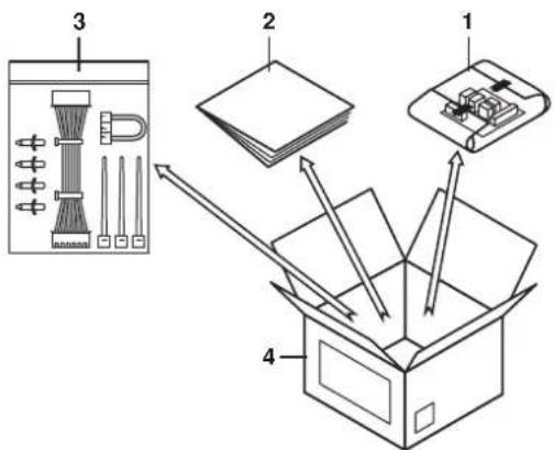
4. ACCESSORIES
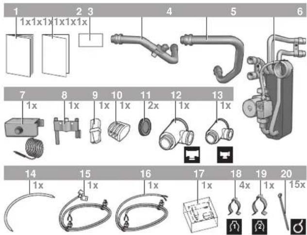
1 Installation manual
2 Addendum for pump station EKSR
3 Wiring diagram sticker
4 Return connection to the 200/260 I domestic hot water tank heat exchanger with piping thermal cut out (incl. reset button)
5 Inlet connection from the domestic hot water tank heat exchanger
6 Plate heat exchanger and pump
7 Domestic hot water tank thermal cut out (incl. reset button)
8 Sensor holder
9 Connector 2-pole
10 Connector 3-pole
11 Grommet
12 T-piece (large)
13 T-piece (small)
14 Wire harness X3 to X2M/21
15 Wire harness Q3L to A1P
16 Wire harness Q3L to X2M/28 and X8Y
17 EKRP1HB solar/remote alarm address card
18 Piping clamp (small)
19 Piping clamp (large)
20 Clamp
5. OVERVIEW OF THE SOLAR KIT
5.1. Main components
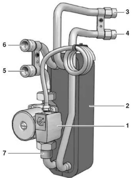
1 Solar kit circulation pump
2 Heat exchanger
3 Inlet connection from solar pump station
4 Return connection to solar pump station
5 Inlet connection from the unit
6 Return connection to the unit
7 Non-return valve
5.2. Safety functions
Domestic hot water tank tank thermal cut out
The solar kit contains a thermal cut out safety device to be mounted on the domestic hot water tank casing. (refer to "7.6. Field wiring" on page 7).
When the thermal cut out safety of the domestic hot water trips, the power supply to the pump of the solar kit is interrupted (and the solenoid 2-way valve (EKUHT2WB for UK-only) is closed) so that no more solar heat can be transferred to the domestic hot water tank. Error code RR will appear on the remote controller, refer to "11.3. Error codes" on page 13.
Piping thermal cut out
Mounted on the piping of the solar kit, a thermal cut out safety protects the piping of the unit and domestic hot water tank against overheating.
When the thermal cut out safety of the piping trips, the power supply to the pump of the solar kit is interrupted (and the solenoid 2-way valve (EKUHT2WB for UK-only) is closed) so that no more solar heat can be transferred to the domestic hot water tank. There will appear no error code on the remote controller. Reset by pressing the reset button.
6. GENERAL SYSTEM SETUP AND OPERATION
The solar kit is designed to transfer the heat from the Daikin solar panels to the heat exchanger of the domestic hot water tank EKHTS* and is to be installed in the system as shown in the scheme below.

1 Solar panels (EKS*26)
2 Solar pump station (EKSRDS1A)
3 Solar pump station controller with temperature sensors (EKSR3PA)
3.1 Domestic hot water tank temperature sensor, T
3.2 Return temperature sensor to solar panels, T
3.3 Supply temperature sensor with flow meter from solar panels (option EKSFLP12A)
3.4 Solar panel temperature sensor, T K
4 Solar kit (EKSOL*)
5 Domestic hot water temperature sensor of the unit
6 Solenoid 2-way valve (only for UK)
Obligatory for compliance to UK building regulation G3.
Refer to the EKUHT2WB kit.
7 Tank thermal cut out device
8 Piping thermal cut out device
Heating system.
Refer to the unit installation manual.
--- Example of unit
The solar panels (1) catch the heat of the sun. When the temperature of the glycol solution in the solar panel has become higher than the water temperature in the domestic hot water tank, the pump of the solar pump station (2) and the pump of the solar kit (4) start to operate as to transfer the heat to the heat exchanger of the domestic hot water tank, unless priority is given to the heat pump. Refer to "10. Operating instructions" on page 11 (subsection: Configuring your system).
7. INSTALLATION OF THE SOLAR KIT
7.1. Selecting an installation location
■ The solar kit is to be installed in a frost free indoor space, directly connected to the domestic hot water tank.
■ Make sure the service space is available as indicated in below drawing.
■ The space around the unit has to allow sufficient air circulation.
It shall be made sure that in the case of a leak, leaking water will not cause any damage or unsafe situations.
■ The equipment is not intended for use in a potentially explosive atmosphere.
■ Do not install or operate the unit in rooms mentioned below:
- Where corrosive gas like sulphurous gas exists: copper tubing and brazed spots may corrode.
- Where volatile flammable gas like thinner or gasoline is used.
- Where machines generating electromagnetic waves exist: the control system may malfunction.
- Where the air contains high levels of salt such as air near the ocean and where voltage fluctuates a lot (e.g. in factories). This applies also to vehicles or vessels.
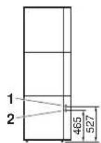
7.2. Dimensions and service space
Service space dimensions below relate to requirements for installation of the solar kit only.
For service space dimensions of the domestic hot water tank, refer to the installation manuals of the domestic hot water tank and of the indoor unit.
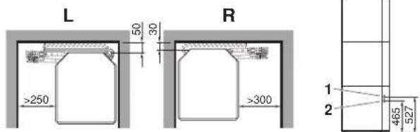
L Left installation
R Right installation
1 Inlet connection from solar pump station
2 Return connection to solar pump station
7.3. Inspecting, handling and unpacking the unit
■ The EKSOLHTBV1 kit is packed in a cardboard box.
■ At delivery, the kit must be checked and any damage must be reported immediately to the carrier claims agent.
- Check if all accessories (see "4. Accessories" on page 3) are enclosed.
■ Bring the kit as close as possible to its final installation position in its original package in order to prevent damage during transport.

CAUTION
Safely dispose of packing materials.

WARNING
Tear apart and throw away plastic packaging bags so that children will not play with them. Children playing with plastic bags face danger of death by suffocation.
7.4. Installation guidelines
■ Make sure that all the piping to the solar kit is insulated.
■ Make sure that all the piping to the solar kit is sufficiently supported so that it will not cause any stress on the solar kit.
■ Make sure the piping is protected against dirt during installation. Dirt in the piping might clog the heat exchanger of the solar panel and reduce its performance.
7.5. Installing the solar kit
■ At delivery, the unit should be checked and any damage should be reported immediately to the carrier claims agent.
■ Check if all unit's accessories are enclosed. Refer to "4. Accessories" on page 3.
■ Bring the unit as close as possible to its final installation position in its original package in order to prevent damage during transport.
Procedure
Follow the steps as shown in the installation drawings below.
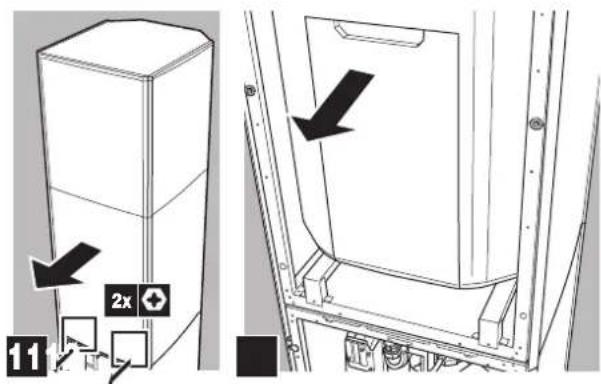
1 Opening of the unit, mounting the wiring diagram sticker on the front decoration panel and removing the switch box.


2 Remove the knock out holes and mount the grommets.

3 Mount the kit inside the unit.


INFORMATION
For installation with EKHTSU domestic hot water tank, do not perform next step as explained below, refer to chapter "8. Installation of solenoid valve kit EKUHT2WB" on page 10 instead.


CAUTION
Do not switch inlet and outlet connections.

CAUTION
Ensure that the water piping connected to the solar kit coming from the solar panel and the unit are sufficiently supported and do not cause any stress on the solar kit.
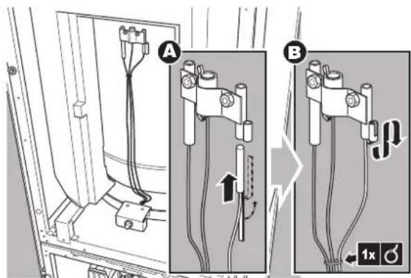
4 Opening the domestic hot water tank.
5 Mounting the thermal cut out.
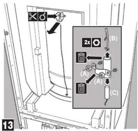
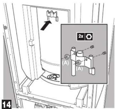

CAUTION
Do not overtighten the nuts.

natural_image
Mechanical assembly diagram showing two blocks with a black arrow indicating a force or movement (no text or symbols present)
natural_image
Technical line drawing of a mechanical clamp or bracket assembly with a screwdriver inserted (no text or symbols)
natural_image
Technical line drawing of a mechanical assembly with no visible text or symbols

WARNING
Ensure that both the thermal cut out and the domestic hot water tank sensor make good contact with the tank body. If no good contact is established, this can cause overheating of the domestic hot water tank.
Charging water
Charge the water on the unit and the tank (refer to the installation manuals of the unit and the domestic hot water tank).
Charge the solar panel circuit with a glycol solution.

CAUTION: Use of glycol
■ Observe the instructions as given by your solar panel supplier. Make sure to use non-toxic glycol.
■ For installations with a domestic hot water tank, the use of propylene glycol, including necessary inhibitors, is only allowed if classified as Category 3 according to EN1717 or equivalent based on national regulations.
7.6. Field wiring

CAUTION
■ Switch off the power supply before making any connections.
■ All field wiring and components must be installed by a licensed electrician and must comply with relevant European and national regulations.
■ The field wiring must be carried out in accordance with the wiring diagram and the instructions given below.
Overview
The illustration below gives an overview of the required field wiring between several parts of the installation. Refer also the wiring diagram, the installation manual of the unit, the domestic hot water tank and the solar pump station.

flowchart
graph TD
    A["Sun"] --> B["1"]
    B --> C["2"]
    C --> D["3"]
    D --> E["4"]
    E --> F["5"]
    F --> G["6"]
    G --> H["7"]
    H --> I["8"]
    I --> J["9"]
    J --> K["10"]
    K --> L["11"]
    L --> M["12"]
    M --> N["13"]
    N --> O["14"]
    O --> P["15"]
    P --> Q["16"]
    Q --> R["17"]
    R --> S["18"]
    S --> T["19"]
    T --> U["20"]
    U --> V["21"]
    V --> W["22"]
    W --> X["23"]
    X --> Y["24"]
    Y --> Z["25"]
A, B Refer to the unit installation manual
C Solar panel
D Solar pump station controller (EKSR3PA)
E Solar pump station (EKSRDS1A)
F Solar kit
G Only for EKHTSU: solenoid 2-way valve
| Item Description | Required number of conductors | Maximum running current | |
| 1 Solar panel sensor cable 2 — | |||
| 2 Domestic hot water temperature sensor of the solar pump station | 2 | — | |
| 3 Solar return temperature sensor 2 — | |||
| 4 Operating signal cable from solar pump station controller to unit | 2 | — | |
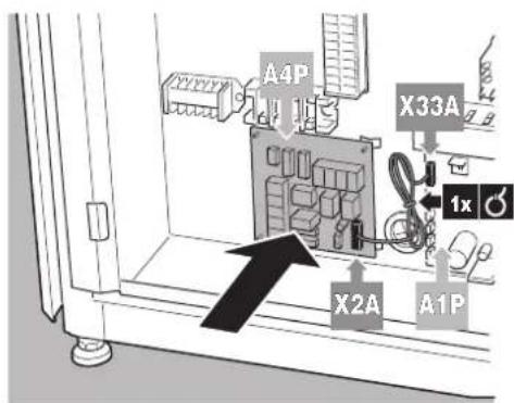
Installing the EKRP1HB in the unit
Install the PCB delivered with the solar kit in the unit.
Refer to "4. Accessories" on page 3, part 8.
1 Open the EKRP1HB box.
1 Wrapped PCB (solar/remote alarm address card)
2 Installation manual
3 Accessories bag
4 EKRP1HB box
2 Take out the PCB and unwrap it.
3 Open the accessories bag and take the connector labelled X1A.
4 Place this connector on the EKRP1HB PCB (on the connector X1A/CN1).

5 Mount the plastic raisers from the accessories bag on the switch box backplate.
6 Mount the EKRP1HB PCB on the plastic raisers.
Mount the control cable (from the accessories bag) between A1P: X33A (the main PCB) and A4P: X2A/CN2 (the EKRP1HB PCB).
Connecting the temperature sensors
1 Mount the solar panel sensor of the solar pump station in the solar panel according to the instructions of the solar pump station and solar panel.
2 Mounting the domestic hot water temperature sensor of the solar pump station must be performed according to instructions of the solar pump station.

NOTICE
The distance between the thermistor cables and the power supply cable must always be at least 5 cm to prevent electromagnetic interference on the thermistor cables.
Connecting the solar pump station controller, solar pump station, indoor unit, domestic hot water tank and solar kit

CAUTION
Make sure no wiring comes in contact with piping.
Otherwise damage to the wiring will occur because some piping does become very hot.
Refer to the figures below.
1 Connecting the domestic hot water thermal cut out
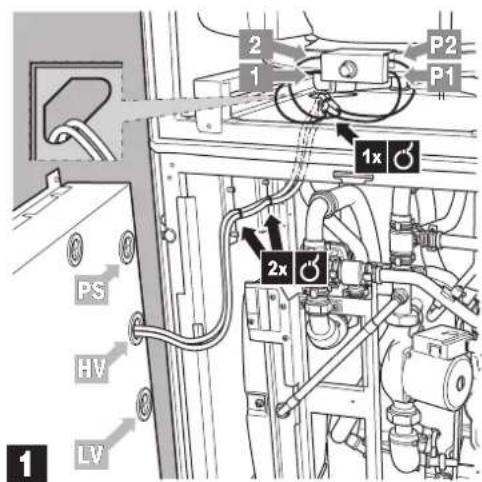
PS Power supply
HV High voltage
LVLow voltage

INFORMATION
For installation with EKHTSU domestic hot water tank, do not perform the next step as explained below, refer to "8. Installation of solenoid valve kit EKUHT2WB" on page 10 instead.
2 Connecting the piping thermal cut out
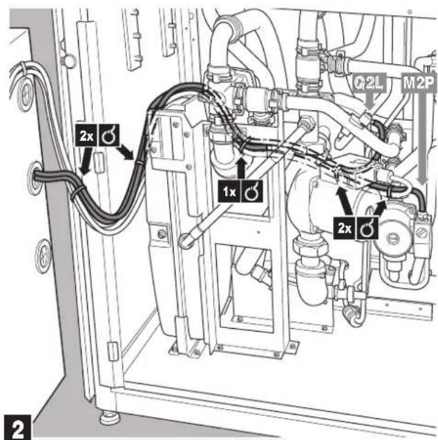
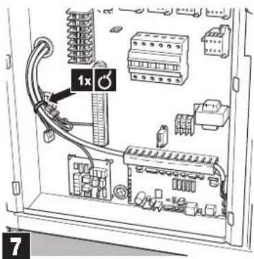
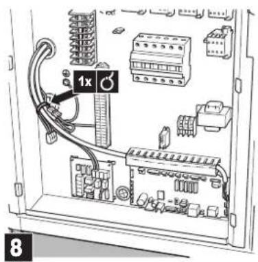
3 Making connection in the switch box
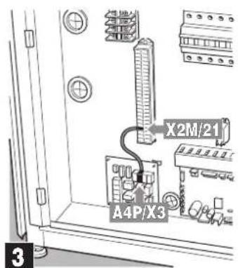
Use wire harness X3 to X2M/21, refer to number 14 of the "Accessories" on page 3.

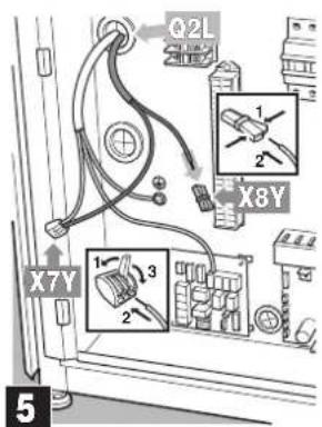

INFORMATION
Only for installations with stand alone domestic hot water tank.
Wire harness Q3L to A1P and wire harness Q3L to X2M/28 and X8Y have to be extended to bridge the distance between the domestic hot water tank and hydrobox.
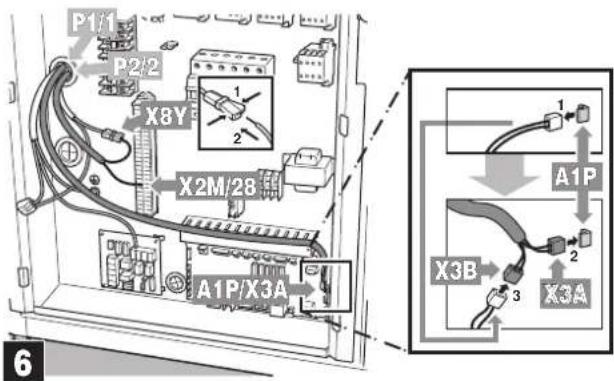
Use wire harness Q3L to A1P, refer to number 15 of the "Accessories" on page 3.
Use wire harness Q3L to X2M/28 and X8Y, refer to number 16 of the "Accessories" on page 3.

INFORMATION
For installation with EKHTSU domestic hot water tank, do perform the next step as explained in "8. Installation of solenoid valve kit EKUHT2WB" on page 10.
4 Connecting solar pump station controller
1 connect solar pump station controller to pump station,
2 connect solar pump station controller to indoor unit,

INFORMATION
Refer to the wiring diagram sticker on the inside of the front decoration panel.

flowchart
graph TD
    BSK["BSK"] -->|1 2 3| EKHV["BKHV*BBEKSR3PA"]
    BSK --> X3["X3"]
    BSK --> X4["Y"]
    BSK --> CY3["CY3"]
    EKHV --> A4P["A4P"]
    EKHV --> X2M["X2M"]
    X2M -->|21 28 29| A4P
    A4P --> X3
    A4P --> X4
    A4P --> CY3
8. INSTALLATION OF SOLENOID VALVE KIT EKUHT2WB
8.1. Last steps of mounting the kit inside the unit
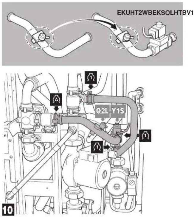

CAUTION
Do not switch inlet and outlet connections.

CAUTION
Ensure that the water piping connected to the solar kit coming from the solar panel and the unit are sufficiently supported and do not cause any stress on the solar kit.
Return to "4 Opening the domestic hot water tank." on page 6 to perform the next steps of the installation.
8.2. Guiding the wiring towards the switch box
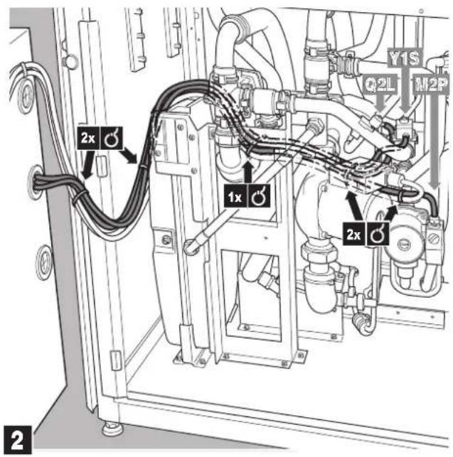
Return to "3 Making connection in the switch box" on page 9 to perform the next steps of the installation.
8.3. Last step of connecting the wiring
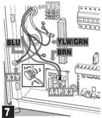
Return to "4 Connecting solar pump station controller" on page 9 to perform the next steps of the installation.
9. START UP
9.1. Commissioning the system before initial start up
Besides the checks before initial start up of the unit (refer to the installation manual of the unit) you must check the following items on the solar kit installation before switching on the circuit breaker:
■ The domestic hot water tank is filled with water. Refer to the installation manual of the domestic hot water tank.
■ The circuit connected to the solar kit is filled with water. Refer to the installation manual of the unit.
■ The solar collector circuit is filled with glycol. Refer to the installation manual of the solar circuit.
■ Make sure the solar kit is properly fixed inside the indoor unit and that there are no leaks.
■ Field wiring and earthing
Make sure the pump of the solar kit is connected to the thermal protectors as shown in the wiring diagram and the pump earth wires have been connected properly. The earth terminals should be tightened.
■ Ensure that the auxiliary contact of the solar pump station is connected to the unit.
■ Mounting of sensors
Make sure the solar panel temperature sensor and the domestic hot water temperature sensor of the solar pump station are properly mounted.
■ Verify that following settings are made on the solar pump station:
■ Maximum solar panel temperature: ≤110°C
■ Maximum tank temperature: 80°C
■ Minimum temperature difference between domestic hot water tank and solar panel before starting pump operation: ≥15°C
9.2. Checklist for proper functioning
Following items should be checked to assure proper functioning:
■ When the temperature of the solar panel becomes 15°C higher than the domestic hot water tank temperature, the pump of the solar pump station and the pump of the solar kit will start operation. ^(1)
$$ d T _ {O N} = \left(T _ {K} - T _ {S}\right) = 1 5 ^ {\circ} C $$
■ When the temperature of the solar panel becomes less than 4^ C higher than the return flow temperature ( T_R ), the pump of the solar pump station and the pump of the solar kit will stop operation.
$$ \mathrm{d} T _ {\text { OFF }} = T _ {K} - T _ {R} \leq 4 ^ {\circ} C $$
10. OPERATING INSTRUCTIONS
10.1. Configuring your system
In order to guarantee maximum energy savings combined with maximum comfort, it is important to configure your system in a proper way.
For this reason, it is strongly recommended to do the following:
Use of schedule timers
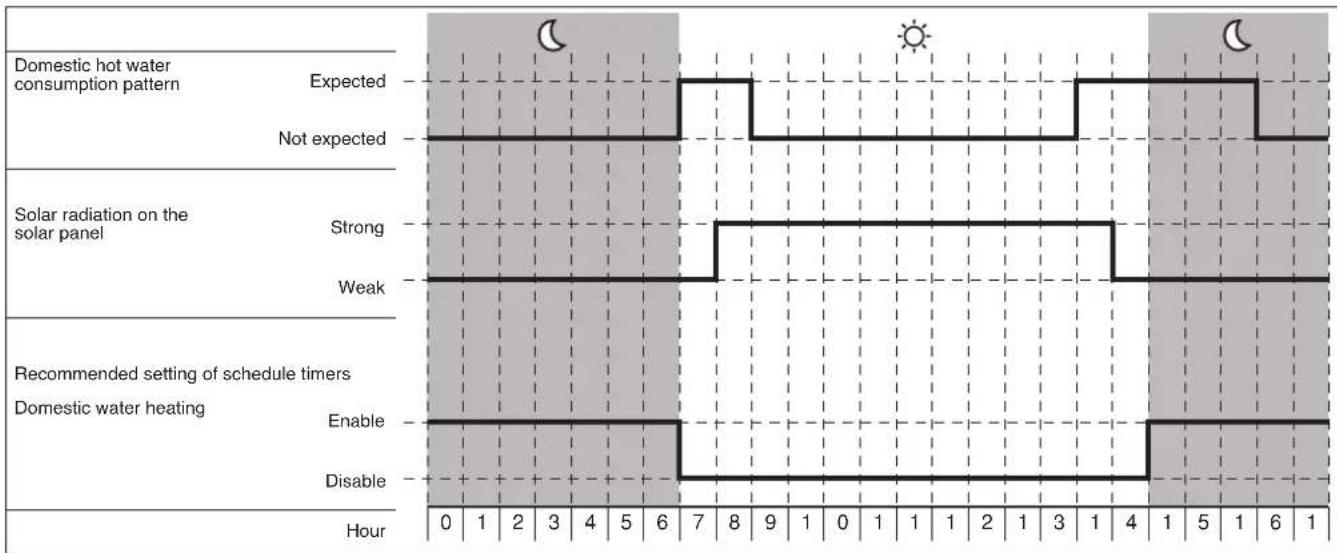
Check the orientation of your solar panel, and find out during what time of the day the intensity of the sun on it is expected to be strong and weak. For example, a solar panel oriented to the east will receive strong intensity during the morning, weak intensity during the afternoon.
■ Check your usual pattern of peak domestic hot water consumption. E.g. showering during the morning from 7 to 9 a.m. and again in the evening from 5 p.m. onwards.
- Check the manual of your indoor unit how to set domestic hot water storage and reheat by the heat pump.
For a system with solar, special care is to be taken to ensure maximum performance of the solar.
■ Scheduled domestic hot water storage must always start after sunset, this to allow the solar to get the maximum heat from the sun. During a sunny day, the solar will heat the domestic water tank completely and the scheduled storage will not be performed.
In case that only scheduled storage is insufficient and a reheat during the day is required:
- Scheduled reheat
Schedule the reheat after midday. In case of a sunny day, the solar will already have heated up the domestic water tank, the reheat by heat pump will not be performed.
- Continuous reheat
Continuous reheat is only recommended in case of exceptionally high domestic hot water demand. The heat pump will heat up the domestic water tank whenever the reheat set point of the domestic hot water tank is reached (default = 35°C). Especially during colder/cloudy days the solar will not be used optimally because a large part is already done by the heat pump.
Example
Your domestic hot water consumption pattern is from 7 a.m. to 9 a.m. in the morning and from 5 p.m. till 11 p.m. in the evening.
Since the solar panel is oriented towards the south-east, the radiation can be intensive on the solar panel from 8 a.m to 6 p.m.
other
| Category | Time (Hour) | Description | | -------- | ----------- | ----------- | | Domestic hot water consumption pattern | 0-6 | Expected | | Domestic hot water consumption pattern | 0-6 | Not expected | | Solar radiation on the solar panel | 0-6 | Strong | | Solar radiation on the solar panel | 0-6 | Weak | | Recommended setting of schedule timers | 0-6 | Enable | | Recommended setting of schedule timers | 0-6 | Disable |Setting of domestic hot water tank temperature
The domestic hot water tank has 2 temperature sensors.
The first temperature sensor is the thermostat sensor of your unit. This temperature can be set on your unit (refer to the operation manual of the unit). It is advised to set this temperature as low as possible. Start with a low temperature, e.g. 48°C. If with this temperature you face shortage of warm water during normal tapping patterns, increase gradually until you find the temperature of warm water that covers your daily demand.

NOTICE
Refer to the operation manual of the unit to change the domestic hot water temperature setting.
The second temperature sensor is the thermostat sensor of the solar pump station. This temperature can be set on the solar pump station. Put this temperature as high as possible but not higher than the listed temperatures in function of domestic hot water tanks installed, as otherwise the thermal protection in the tank might trip = 80°C.

NOTICE
For optimal solar efficiency and system operation it is advised that domestic hot water temperature setting on the unit controller is lower than the temperature setting on the solar pump station controller.
With above settings, the heating of the water by heat pump heater will be limited to the minimum required, and solar heat will be stocked in the domestic hot water tank to the maximum.
Setting of the solar priority parameter
Simultaneous water heating by the sun and water heating by the heat pump is not possible.
By default, heating of the tank by the heat pump has priority over heating by the sun.
This means that, whenever there is a request of the domestic hot water thermostat and domestic water heating is enabled (by the schedule timer or domestic water heating ON/OFF button, refer to the operation manual of the unit), heating will be done by the heat pump. In case solar heating is busy, solar heating will be stopped.
This is to avoid shortage of domestic hot water in case the solar radiation is very weak, or solar radiation only became high shortly before domestic hot water demand is expected (e.g. on a cloudy day).
This default setting can be changed, so that at all times, when solar heat becomes available, domestic water heating by the heat pump will be (if busy) interrupted and taken over by the sun.
In order to change this, put the field parameter [C-00] to 0. Refer to the installation manual of the unit, paragraph "Field settings" to find out how to access and change field parameters. [C-00] put to 0 means solar priority, [C-01] put to 1 means heat pump priority.

NOTICE
Be aware that setting this parameter to 0 might cause insufficient warm water at the time of domestic hot water demand during days with weak solar intensity.
If you are not sure about the availability of hot water, check the domestic hot water temperature on the controller (see operation manual of the unit) and if too low, push the 'powerful' button. This will trigger domestic water heating by the heat pump immediately.

INFORMATION
For a detailed decision flow on domestic water heating by solar kit or by heat pump, refer to the annexes "Decision flow of heating the domestic water by heat pump or by solar kit" on page 14.
11. TROUBLESHOOTING AND SERVICING
This section provides useful information for diagnosing and correcting certain troubles which may occur with the unit.
11.1. General guidelines
Before starting the troubleshooting procedure, carry out a thorough visual inspection of the unit and look for obvious defects such as loose connections or defective wiring.
Before contacting your local Daikin dealer, read this chapter carefully, it will save you time and money.

WARNING
When carrying out an inspection on the switch box of the unit, always make sure the main switch of the unit is switched off.
When a safety device was activated, stop the unit and find out why the safety device was activated before resetting it. Under no circumstances safety devices may be bridged or changed to a value other than the factory setting. If the cause of the problem cannot be found, call your local dealer.
11.2. General symptoms
Symptom 1: The pump of the solar pump station starts operation, but the pump of the solar kit is not working.
| POSSIBLE CAUSE CORRECTIVE ACTION | ||
| 1 | The tank has reached its maximum allowed temperature (see the temperature reading on the unit display) | Refer to "Domestic hot water tank tank thermal cut out" on page 4. |
| 2 | The auxiliary contact from the solar pump station to the unit is not properly wired | Check the wiring. |
| 3 | The pump of the solar kit is not properly wired to the unit | Check the wiring. |
| 4 | The priority for domestic water heating is given to the heat pump | Refer to "Setting of the solar priority parameter" on page 12. |
| 5 | The thermal cut out of the tank has operated | Refer to error code RR in "11.3. Error codes" on page 13. |
| 6 | The thermal cut out of the piping has operated | Reset protection on the piping |
Symptom 2: There is a lot of sun intensity but the solar pump station and solar kit pumps do not start.
| POSSIBLE CAUSE CORRECTIVE ACTION | ||
| 1 | The maximum temperature of the domestic hot water tank is reached | Check the domestic hot water temperature on the controller of the unit (refer to the operation manual of the unit) and check the maximum temperature setting on your solar pump station. |
| 2 | The outdoor unit is heating up the domestic water tank, since the priority for domestic water heating is given to the heat pump | Refer to "Setting of the solar priority parameter" on page 12. |
Symptom 3: Only for EKHTSU
The pump of the solar pump station starts operation, but the pump of the solar kit is not working.
| POSSIBLE CAUSE CORRECTIVE ACTION | ||
| 1 | The 2-way valve remains closed. | Check the wiring.Refer to the wiring diagram on the inside of the front decoration panel. |
11.3. Error codes
When a safety device is activated, the user interface LED will be flashing, and an error code will be displayed.
Following error codes might be related to a malfunction of your solar system. First, check also the corrective actions as mentioned in the installation manual.
Reset the safety by turning the unit OFF and back ON.
| Instruction to turn the unit OFF | |||
| User Interface mode (heating/cooling ⏻/✗) | Domestic water heating mode (✗) | Push the 🎨 button | Push the 🔍 button |
| ON ON 1 time 1 time | |||
| ON OFF 1 time — | |||
| OFF ON — 1 time | |||
| OFF OFF — | — | ||
In case this procedure for resetting the safety is not successful, contact your local dealer.
| Error code | Failure cause Corrective action | |
| RR Domestic hot water tank thermal protector is open | The maximum allowed temperature setting on the solar pump station is set too high. (should be set below 80°C. Reset thermal cut out on the domestic hot water tank. | |
| Backup heater thermal protector is open | ||
| Check the reset button of the thermal protector. If both the thermal protector and the controller are reset, but the RR error code persists, the backup heater thermal fuse has blown. | ||
12. DISPOSAL REQUIREMENTS
Dismantling of the unit, treatment of the refrigerant, of oil and of other parts must be done in accordance with relevant local and national legislation.

Your product is marked with this symbol. This means that electrical and electronic products shall not be mixed with unsorted household waste.
Do not try to dismantle the system yourself: the dismantling of the system, treatment of the refrigerant, of oil and other parts must be done by a qualified installer in accordance with relevant local and national legislation.
Units must be treated at a specialized treatment facility for re-use, recycling and recovery. By ensuring this product is disposed off correctly, you will help to prevent potential negative consequences for the environment and human health. Please contact the installer or local authority for more information.
13. TECHNICAL SPECIFICATIONS
| • Maximum operating pressure of the connections to and from the solar pump station | 6 bar |
| • Maximum operating pressure of the connections to and from the unit and connections to and from the domestic hot water tank heat exchanger | 4 bar |
| • Minimum/maximum ambient temperature | 1/35°C |
| • Minimum/maximum fluid temperature 1/110°C | |
| • Heat transfer liquid (solar side) | propylene glycol |
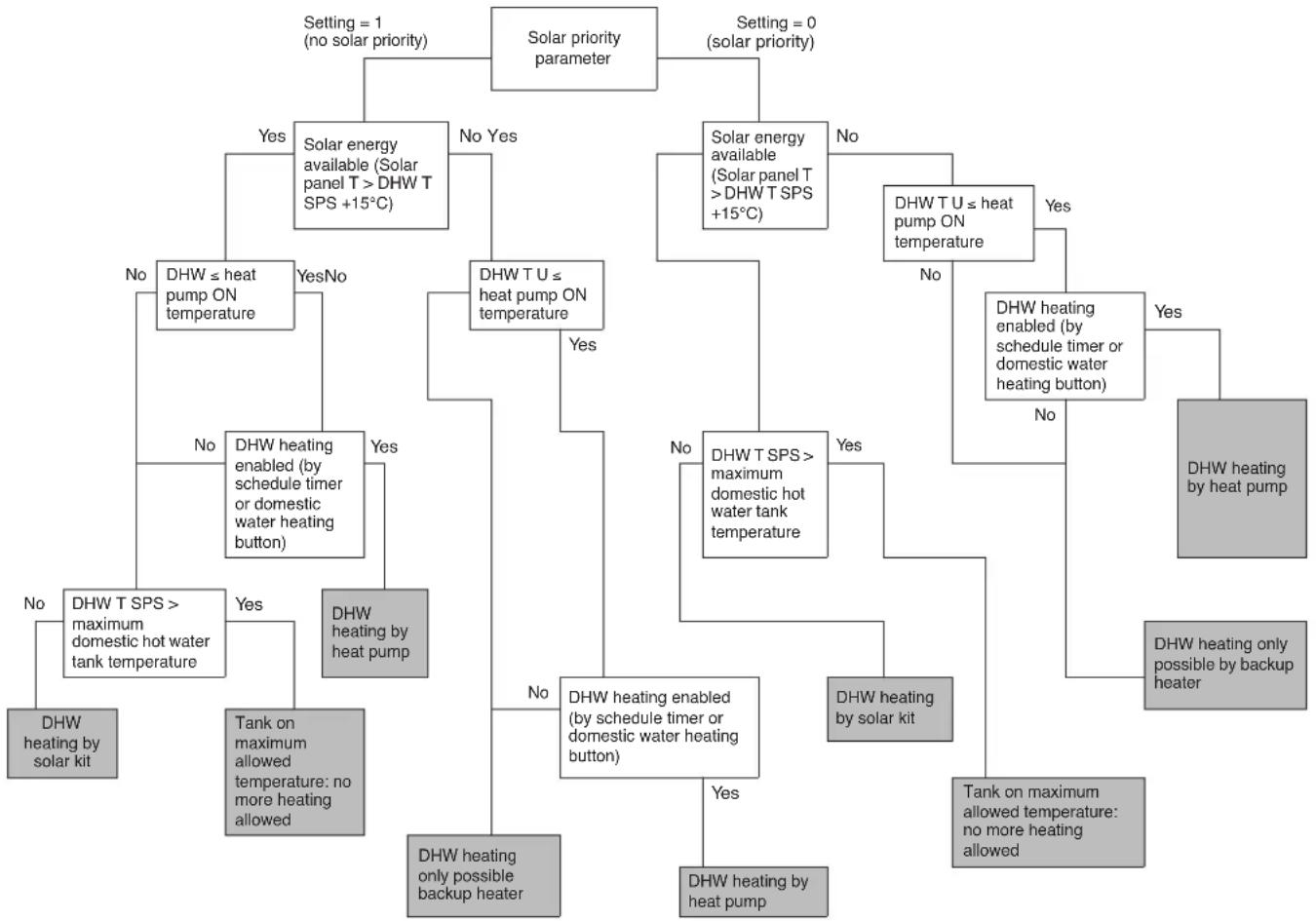
Decision flow of heating the domestic water by heat pump or by solar kit
flowchart
graph TD
    A["Solar priority parameter"] -->|Setting = 1 (no solar priority)| B["Solar energy available (Solar panel T > DHW T SPS +15°C)"]
    A -->|Setting = 0 (solar priority)| C["Solar energy available (Solar panel T > DHW T SPS +15°C)"]
    B -->|Yes| D["DHW ≤ heat pump ON temperature"]
    B -->|No| E["DHW T U ≤ heat pump ON temperature"]
    C -->|Yes| F["DHW T U ≤ heat pump ON temperature"]
    C -->|No| G["DHW T U ≤ heat pump ON temperature"]
    D --> H["DHW ≤ heat pump ON temperature"]
    E --> I["DHW T U ≤ heat pump ON temperature"]
    F --> J["DHW T U ≤ heat pump ON temperature"]
    G --> K["DHW T U ≤ heat pump ON temperature"]
    H --> L["DHW heating enabled (by schedule timer or domestic water heating button)"]
    I --> M["DHW heating enabled (by schedule timer or domestic water heating button)"]
    J --> N["DHW heating enabled (by schedule timer or domestic water heating button)"]
    K --> O["DHW heating enabled (by schedule timer or domestic water heating button)"]
    L --> P["DHW heating enabled (by schedule timer or domestic water heating button)"]
    M --> Q["DHW heating enabled (by schedule timer or domestic water heating button)"]
    N --> R["DHW heating enabled (by schedule timer or domestic water heating button)"]
    O --> S["DHW heating enabled (by schedule timer or domestic water heating button)"]
    P --> T["DHW heating enabled (by schedule timer or domestic water heating button)"]
    Q --> U["DHW heating enabled (by schedule timer or domestic water heating button)"]
    R --> V["DHW heating enabled (by schedule timer or domestic water heating button)"]
    S --> W["DHW heating enabled (by schedule timer or domestic water heating button)"]
    T --> X["DHW heating enabled (by schedule timer or domestic water heating button)"]
    U --> Y["DHW heating enabled (by schedule timer or domestic water heating button)"]
    V --> Z["DHW heating enabled (by schedule timer or domestic water heating button)"]
    W --> AA["DHW heating enabled (by schedule timer or domestic water heating button)"]
    X --> AB["DHW heating enabled (by schedule timer or domestic water heating button)"]
    Y --> AC["DHW heating enabled (by schedule timer or domestic water heating button)"]
    Z --> AD["DHW heating enabled (by schedule timer or domestic water heating button)"]
    AA --> AE["DHW heating enabled (by schedule timer or domestic water heating button)"]
    AB --> AF["DHW heating enabled (by schedule timer or domestic water heating button)"]
    AC --> AG["DHW heating enabled (by schedule timer or domestic water heating button)"]
    AD --> AH["DHW heating enabled (by schedule timer or domestic water heating button)"]
    AE --> AI["DHW heating enabled (by schedule timer or domestic water heating button)"]
    AF --> AJ["DHW heating enabled (by schedule timer or domestic water heating button)"]
    AG --> AK["DHW heating enabled (by schedule timer or domestic water heating button)"]
    AH --> AL["DHW heating enabled (by schedule timer or domestic water heating button)"]
    AI --> AM["DHW heating enabled (by schedule timer or domestic water heating button)"]
    AJ --> AN["DHW heating enabled (by schedule timer or domestic water heating button)"]
    AK --> AO["DHW heating enabled (by schedule timer or domestic water heating button)"]
    AL --> AP["DHW heating enabled (by schedule timer or domestic water heating button)"]
    AM --> AQ["DHW heating enabled (by schedule timer or domestic water heating button)"]
    AN --> AR["DHW heating enabled (by schedule timer or domestic water heating button)"]
    AO --> AS["DHW heating enabled (by schedule timer or domestic water heating button)"]
    AP --> AT["DHW heating enabled (by schedule timer or domestic water heating button)"]
    AQ --> AU["DHW heating enabled (by schedule timer or domestic water heating button)"]
    AR --> AV["DHW heating enabled (by schedule timer or domestic water heating button)"]
DHW Domestic Hot Water
DHW T SPS Domestic Hot Water Temperature by the Solar Pump Station temperature sensor
DHWTU Domestic Hot Water Temperature by the Unit temperature sensor
*4PW67028-1 A 0000000P*
- INSTALLATION AND OPERATION MANUAL
- CONTENTS Page
- DEFINITIONS
- Meaning of warnings and symbols
- DANGER
- WARNING
- CAUTION
- NOTICE
- INFORMATION
- Meaning of used terms
- Installation manual:
- Operation manual:
- Maintenance instructions:
- Dealer:
- Installer:
- User:
- Service company:
- Applicable legislation:
- Accessories:
- Optional equipment:
- Field supply:
- GENERAL SAFETY PRECAUTIONS
- DANGER: DO NOT TOUCH PIPING AND INTERNAL PARTS
- INTRODUCTION
- General information
- Scope of this manual
- Model identification
- ACCESSORIES
- OVERVIEW OF THE SOLAR KIT
- Main components
- Safety functions
- Piping thermal cut out
- GENERAL SYSTEM SETUP AND OPERATION
- INSTALLATION OF THE SOLAR KIT
- Selecting an installation location
- Dimensions and service space
- Inspecting, handling and unpacking the unit
- Installation guidelines
- Installing the solar kit
- Procedure
- Mounting the thermal cut out.
- Charging water
- CAUTION: Use of glycol
- Field wiring
- Overview
- Installing the EKRP1HB in the unit
- Connecting the temperature sensors
- INSTALLATION OF SOLENOID VALVE KIT EKUHT2WB
- Last steps of mounting the kit inside the unit
- Guiding the wiring towards the switch box
- Last step of connecting the wiring
- START UP
- Commissioning the system before initial start up
- Checklist for proper functioning
- OPERATING INSTRUCTIONS
- Configuring your system
- Use of schedule timers
- Example
- Setting of domestic hot water tank temperature
- Setting of the solar priority parameter
- TROUBLESHOOTING AND SERVICING
- General guidelines
- General symptoms
- Error codes
- DISPOSAL REQUIREMENTS
- TECHNICAL SPECIFICATIONS
Brand : DAIKIN
Model : EKSOLHTBV1
Category : Water heater